energy methods for pole and fixed object impacts · energy methods for pole and fixed object impact...
TRANSCRIPT

Energy Methods for Pole and Fixed Object Impact© 2002 John Daily 1
Copyright 2005 John Daily
Energy Methods for Pole and Narrow Object Impacts
Presented By:John DailyJackson Hole Scientific Investigations, IncBox 2206Jackson, WY 83001July 27, 2005SCARS Conference
Copyright 2005 John Daily
The ProblemVehicles often leave the road and impact with narrow objects.Narrow objects do not move in the same sense as an unconstrained object.However, narrow objects, particularly poles, can break away.The vehicle coming into the collision is the only energy source to do damage.For our purposes, a narrow object is less than ¼ the width of the vehicle.

Energy Methods for Pole and Fixed Object Impact© 2002 John Daily 2
Copyright 2005 John Daily
The Problem, cont’d.We must account for all of the energy dissipated by the vehicle.A Combined Speed equation enables us to add KE.In Section 1 of this presentation, we will examine pre and post impact vehicle motion.In Section 2, we will examine vehicle impact damage and EBS.In Section 3, we will look at pole properties, including fracture energy.In Section 4, we will determine the EBS for pole movement.In Section 5, we will examine test results from a staged crash.
Copyright 2005 John Daily
What Do We Need?
Identify the overall path of the vehicle and list what it did.Pre-Impact skidding? CSY?Pole or other fixed object collision?How much vehicle damage?How much damage to the pole?How much did the pole move?Post-Impact motion?

Energy Methods for Pole and Fixed Object Impact© 2002 John Daily 3
Copyright 2005 John Daily
Section 1
Pre and Post Impact Vehicle Movement
Copyright 2005 John Daily
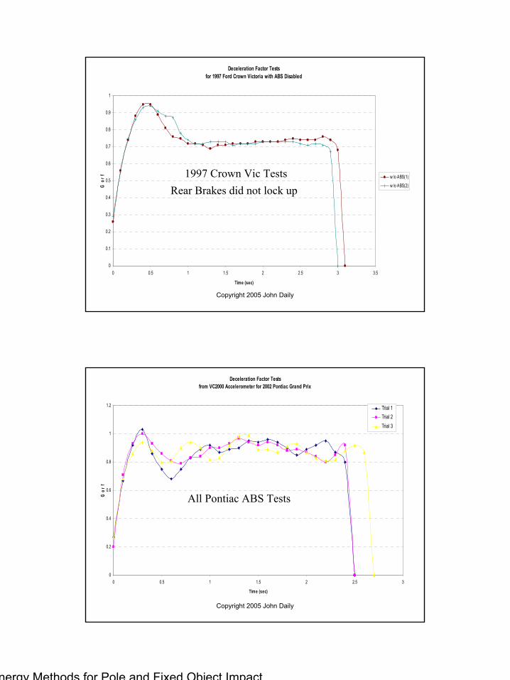
Pre-Impact SkiddingVehicles may skid with locked wheels into the impact.ABS braking treated in the same way.The skid distance is not usually the problem.We must take care to ensure we use the proper drag factor.The following graphs show typical deceleration.
Energy Methods for Pole and Fixed Object Impact© 2002 John Daily 4
Copyright 2005 John Daily
Deceleration Factor Testsfor 1997 Ford Crown Victoria with ABS Disabled
0
0.1
0.2
0.3
0.4
0.5
0.6
0.7
0.8
0.9
1
0 0.5 1 1.5 2 2.5 3 3.5
Time (sec)
G o
r f w /o ABS(1)
w /o ABS(2)
1997 Crown Vic TestsRear Brakes did not lock up
Copyright 2005 John Daily
Deceleration Factor Testsfrom VC2000 Accelerometer for 2002 Pontiac Grand Prix
0
0.2
0.4
0.6
0.8
1
1.2
0 0.5 1 1.5 2 2.5 3
Time (sec)
G o
r f
Trial 1Trial 2Trial 3
All Pontiac ABS Tests

Energy Methods for Pole and Fixed Object Impact© 2002 John Daily 5
Copyright 2005 John Daily
Deceleration Factor Test1997 Ford Crown Victoria with ABS Disabled
0
0.1
0.2
0.3
0.4
0.5
0.6
0.7
0.8
0.9
1
0 0.5 1 1.5 2 2.5 3 3.5 4 4.5 5Time (sec)
G's
Drag Factor
Average
Test skid from 73 mph
Copyright 2005 John Daily
Acceleration Factor Testsfrom VC2000 Accelerometer
0
0.2
0.4
0.6
0.8
1
1.2
0 0.5 1 1.5 2 2.5 3 3.5 4 4.5 5
Time (sec)
G o
r f
Trial 1
Trial 2
Trial 3
w / ABS
w /o ABS(1)
w /o ABS(2)
hi speed
All Test Skids

Energy Methods for Pole and Fixed Object Impact© 2002 John Daily 6
Copyright 2005 John Daily
Pre-Impact Skidding, cont’d
The graphs show us a constant drag factor over a given surface.What if we have multiple surfaces or all wheels are not braking?
Use the following drag factor equation or its derivative:
f = µncosθ + sinθ
Copyright 2005 John Daily
Pre-Impact Skidding, cont’d.
f = drag factorµ= road friction coefficient (level road drag factor)n = percentage of brakingθ = slope angle in degrees

Energy Methods for Pole and Fixed Object Impact© 2002 John Daily 7
Copyright 2005 John Daily
Pre-Impact Skidding, cont’d.
If the slope angle is small (6 degrees or less) then:cosθ ≈ 1sinθ ≈ tanθ = Percent slope (m)
f = µn + m
Copyright 2005 John Daily
Pre-Impact Skidding, cont’d.
We now use the slide to stop or combined speed equation to determine the pre-impact energy loss speed equivalent:
)...(30 332211 nndfdfdfdfS ++++=

Energy Methods for Pole and Fixed Object Impact© 2002 John Daily 8
Copyright 2005 John Daily
Pre-Impact Movement
Critical Speed Yaw
Copyright 2005 John Daily

Energy Methods for Pole and Fixed Object Impact© 2002 John Daily 9
Copyright 2005 John Daily
Road Evidence
In order to properly analyze a critical speed yaw situation, we must properly measure the tire mark evidence left behind.
We will measure the grade and superelevation where the rear tires begin tracking outside the front tires.
Note the diagonal striation direction in the example photos.
Copyright 2005 John Daily
Measuring Grade

Energy Methods for Pole and Fixed Object Impact© 2002 John Daily 10
Copyright 2005 John Daily
Measuring Super-elevation
Copyright 2005 John Daily
Yaw Marks, cont’d.
This is a CSY mark left with no braking.Note the direction of the striations in the tire mark.

Energy Methods for Pole and Fixed Object Impact© 2002 John Daily 11
Copyright 2005 John Daily
Yaw Marks, cont’d.
This is a CSY mark left with braking.Note the direction of the striations in the tire mark.As the brake force increases, the angle of the striations approaches parallel.
Copyright 2005 John Daily
Yaw Marks, cont’d.This is a CSY mark left with ABS braking.Note the direction of the striations in the tire mark change as the ABS system cycles.

Energy Methods for Pole and Fixed Object Impact© 2002 John Daily 12
Copyright 2005 John Daily
Yaw Marks, cont’d.Transition from CSY to full, non-ABS braking.This evidence may be left by the panicked, untrained driver who inappropriately steers and then brakes to maximum.The yaw portion follows the CSY model.
Copyright 2005 John Daily
Radius DeterminationIn order to obtain a path radius, we first measure a chord of the arc left by the outside front tire.A chord is any line that cuts the arc at two points.The chord beginning is right after the rear tire mark crosses over the front tire mark.Chord lengths should be between 30 and 50 feet.

Energy Methods for Pole and Fixed Object Impact© 2002 John Daily 13
Copyright 2005 John Daily
Radius Determination, cont’d.After we have laid down the chord measurement, we have to determine a middle ordinate.The middle ordinate divides the chord in half and extends out to far the edge of the tire mark.For a 30 foot chord, measure the middle ordinate to the nearest 1/8 inch.
Copyright 2005 John Daily
Radius Determination, cont’d.Once we have chord and middle ordinate measurements, we may calculate the radius of the outside front tire mark with the following equation:To get the CM radius, subtract ½ of the track width from this calculation.
28
2 mmcR +=

Energy Methods for Pole and Fixed Object Impact© 2002 John Daily 14
Copyright 2005 John Daily
Critical Speed Equations
Radius Equation
Critical Speed Yaw Equation
Longitudinal Drag Factor Equation
28
2 mmcR +=
rfS 86.3=
dSS
f fo
30
22 −=
Copyright 2005 John Daily
Critical Speed YawThe vehicle will generally slow if in a CSY.Solve first for two radii. The chord from the second will be measured from the end of the first.Next, calculate two speeds. The first should be higher than the second.Using the two speeds, calculate the yaw deceleration.The impact speed with the pole will then be nominally less than the CSY speed calculated.

Energy Methods for Pole and Fixed Object Impact© 2002 John Daily 15
Copyright 2005 John Daily
Post Impact Movement
If a vehicle hits a pole off-center it will usually rotate away from the collision.A simple slide to stop analysis won’t always work.We will examine a way to determine the speed of a spinning vehicle.Consider the following diagram:
Copyright 2005 John Daily
This vehicle has come to rest after impact, leaving the tire marks shown.

Energy Methods for Pole and Fixed Object Impact© 2002 John Daily 16
Copyright 2005 John Daily
Plot the vehicle back at its skid initiation point.
Draw a station line parallel to the initial velocity vector of the vehicle.
Draw offset lines perpendicular to the station line every 10 or 20 feet.
Copyright 2005 John Daily
Plot the vehicle heading by placing the vehicle back on its tire marks, locating the center of mass on the appropriate offset line.

Energy Methods for Pole and Fixed Object Impact© 2002 John Daily 17
Copyright 2005 John Daily
Determine velocity vector bearing tangent to the vehicle path at each CM location.
The angle the vehicle makes with respect to its velocity will be the difference between bearing and heading.
Use the CAD program to determine the center of mass distance moved between each offset line.
Once we know this information, we can calculate the drag factor for this vehicle for each distance increment.
We may then calculate speed using a combined speed equation.
For this example, we will use µ= 0.75
Copyright 2005 John Daily
Total44.27
Total96.1 ft
2.30.168.224193°13.7
2.84.219.292163°13.0
7.11.574.766130°12.4
8.31.699.933111°11.9
8.63.744.99283°11.6
7.87.673.89864°11.7
5.56.501.66942°11.1
1.65.155.20712°10.7
fndnf =
µnsinθ+mSin θθDistance

Energy Methods for Pole and Fixed Object Impact© 2002 John Daily 18
Copyright 2005 John Daily
Post Impact Movement
Use Combined Speed Equation:
S = 36.44 mphEffective Drag Factor: 0.46Percentage of Braking: 0.61
)...(30 332211 nndfdfdfdfS ++++=
Copyright 2005 John Daily
Section 2
Vehicle Impact Damage and EBS

Energy Methods for Pole and Fixed Object Impact© 2002 John Daily 19
Copyright 2005 John Daily
Vehicle Impact Damage
Copyright 2005 John Daily
Vehicle Impact Damage
Vehicles may impact with poles in any number of configurations:
FrontalSideRearOther Surface Sideswipe

Energy Methods for Pole and Fixed Object Impact© 2002 John Daily 20
Copyright 2005 John Daily
Vehicle Impact Damage, cont’d.
Frontal ImpactsMost information availableSeveral different methods useful for analysis
Maximum crush techniques (ex. Craig Method)Damage profile techniques (ex. CRASH lll)
Copyright 2005 John Daily
Vehicle Impact Damage, cont’d.
Side ImpactsNot as much information availableSide structures contain some hard points
A-pillar (hard) v doors (soft)
Analysis limited to damage profile techniquesGood stiffness data lacking

Energy Methods for Pole and Fixed Object Impact© 2002 John Daily 21
Copyright 2005 John Daily
Vehicle Impact Damage, cont’d.
Rear ImpactsInformation lackingDamage profile technique
Not much stiffness data available
Copyright 2005 John Daily
Vehicle Impact Damage, cont’d.
Other surface impacts

Energy Methods for Pole and Fixed Object Impact© 2002 John Daily 22
Copyright 2005 John Daily
Vehicle Impact Damage, cont’d.
Other surface impactsProblematic
No stiffness or strength data availableSignificant bending of whole structure may be presentAs of now, no techniques availablePerhaps FEA in the future
Copyright 2005 John Daily
Vehicle Impact Damage, cont’d.
SideswipesCannot use maximum crush depth or damage profile techniquesNot enough information for maximum depthDamage centroids do not reach a common velocity for a CRASH lll or similar analysisMIGHT(?) be able to approximate with slide to stop and a drag factor sliding past the pole.Be very careful with this…

Energy Methods for Pole and Fixed Object Impact© 2002 John Daily 23
Copyright 2005 John Daily
Vehicle Impact Damage, cont’d.
Sometimes we have a collision on the frontal surface of the vehicle….
And it is a REALLY good WHACK!!
Copyright 2005 John Daily
Vehicle Impact Damage, cont’d.This pickup drove off the road and hit squarely an immovable object.The speed change was obviously quite high.There is too much damage to apply a CRASH III type of analysis.From examining the damage to the vehicle, we see the collision force was virtually straight back.
Energy Methods for Pole and Fixed Object Impact© 2002 John Daily 24
Copyright 2005 John Daily
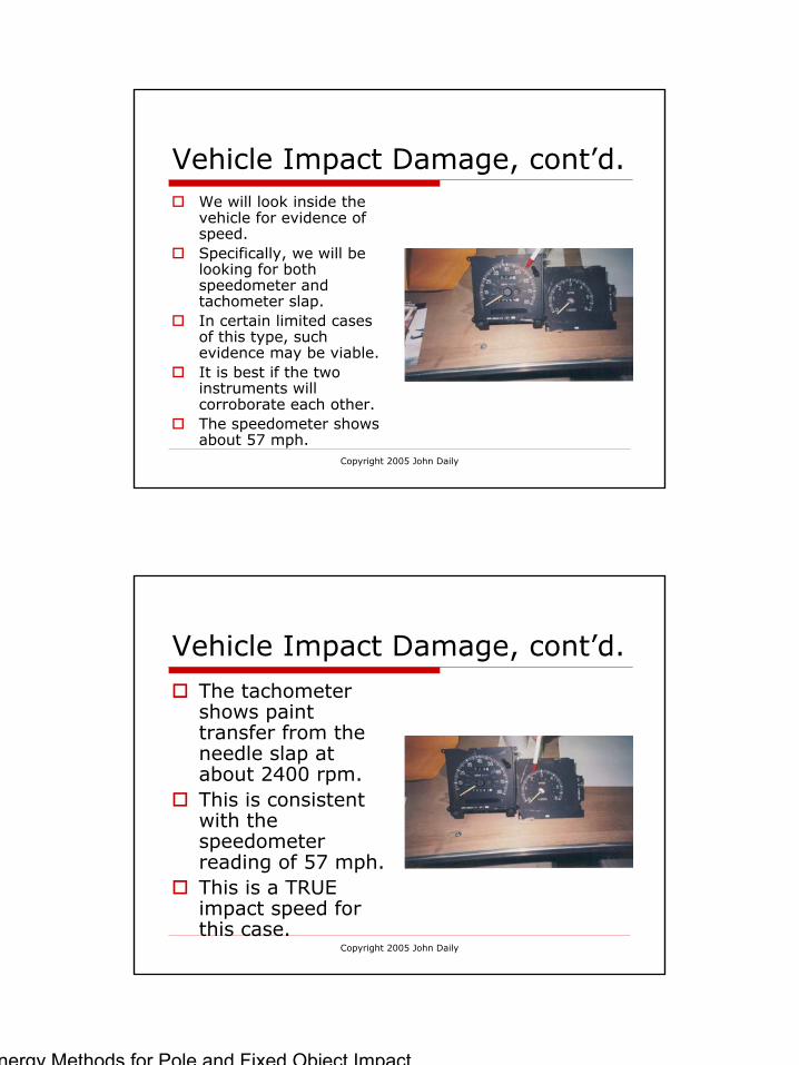
Vehicle Impact Damage, cont’d.We will look inside the vehicle for evidence of speed.Specifically, we will be looking for both speedometer and tachometer slap.In certain limited cases of this type, such evidence may be viable.It is best if the two instruments will corroborate each other.The speedometer shows about 57 mph.
Copyright 2005 John Daily
Vehicle Impact Damage, cont’d.The tachometer shows paint transfer from the needle slap at about 2400 rpm.This is consistent with the speedometer reading of 57 mph.This is a TRUE impact speed for this case.

Energy Methods for Pole and Fixed Object Impact© 2002 John Daily 25
Copyright 2005 John Daily
Determining Vehicle EBSThe term EBS stands for “Equivalent Barrier Speed”.It may also be called BEV, for “Barrier Equivalent Velocity”A “Barrier” is a non-movable object that absorbs none of the collision energy.Hence, the EBS is the impact speed of the vehicle into a barrier with no motion of the vehicle after impact. Thus, EBS represents the kinetic energy required to crush the vehicle to its noted damage profile.
Copyright 2005 John Daily
Determining Vehicle EBS
With pole impacts, there are two methods commonly used to determine vehicle EBS:
Maximum Crush TechniquesDamage Profile Techniques

Energy Methods for Pole and Fixed Object Impact© 2002 John Daily 26
Copyright 2005 John Daily
Determining Vehicle EBSMaximum Crush Techniques
Several different equations have been developed by researchers which use the maximum crush of the vehicle to determine EBS.Of these, we will examine the Craig models.Victor Craig published the following article in the Sept/Oct 1993 AR Journal: “Analysis of Pole Barrier Test Data and Impact Equations”.In this article, he suggests a “rule of thumb” of one mph per inch of deformation in a frontal crash with a small, front wheel drive car. A “small” car is less than 15 feet long with a weight under 3000 lbs.
Copyright 2005 John Daily
Determining Vehicle EBSCraig further reports this “rule of thumb” may be modified for crush depth in the following manner:
For crush depths up to 20 inches, use the crush depth with no modification.For depths between 21 & 25 inches, add one inch.For depths between 26 & 30 inches, add 2 inches.For depths between 31 & 35 inches, add 3 inches.For depths between 36 & 40 inches, add 4 inches.For depths between 41 & 45 inches, add 5 inches.Thus, a small front wheel drive car with a measured depth of crush of 45 inches would have an EBS of 50 mph.

Energy Methods for Pole and Fixed Object Impact© 2002 John Daily 27
Copyright 2005 John Daily
Determining Vehicle EBS
Craig did additional work on the subject, published in the ARJ, Sept/Oct 1995, “Speed Estimation in Head-on Vehicle Pole Impacts – Update”.The following four equations are presented, which account for different vehicle sizes and crush depth regions.
Copyright 2005 John Daily
Determining Vehicle EBSSmall FWD with maximum crush less than or equal to one foot:
EBS = 0.47Cmax + 4.0Small FWD with maximum crush greater than one foot:
EBS = 1.30Cmax – 6.0Mid/Full size with max crush less than or equal to 1.5 feet:
EBS = 0.54Cmax + 4.0Mid/Full size with max crush greater than 1.5 feet:
EBS = 1.18Cmax – 7.0

Energy Methods for Pole and Fixed Object Impact© 2002 John Daily 28
Copyright 2005 John Daily
Determining Vehicle EBSCraig reports this method, after the analysis of 47 crash tests, will predict the EBS within 5 mph 100% of the time.
Copyright 2005 John Daily
Determining Vehicle EBSDamage Profile Technique
The CRASH III model, which was developed from the initial work of Emori and Campbell uses the actual damage profile for EBS calculations.Essentially, the CRASH III model assumes certain uniform stiffness characteristics over the damage face of the vehicle.The model further assumes the vehicle deforms according to Hooke’s Law, which describes the deflection of a linear spring.

Energy Methods for Pole and Fixed Object Impact© 2002 John Daily 29
Copyright 2005 John Daily
Determining Vehicle EBSDamage Profile Technique
The CRASH III method has two parts: (1)The impact model, which uses computed damage energy to calculate the magnitude of the ∆V vector.This impact model requires the centroids of the damage areas to reach a common velocity.The impact model further requires the calculation of an effective mass ratio, γ.γ is also the ratio of the acceleration of the CM to the centroid of the damage area.The effective mass ratio will assist in determining vehicle rotation.
Copyright 2005 John Daily
Determining Vehicle EBSDamage Profile Technique
The CRASH III method has two parts: (2)The energy model, which uses the damage profile to calculate the energy required to deform the vehicle.This model requires we know the Area of the damage, the depth of the damage centroid, and the A, B, & G stiffness coefficients.We must also specify the angle the P.D.O.F. makes with respect to the damage face so the proper magnification factor, (1 + tan2α) may be calculated.The CRASH III model is NOT valid for sideswipe collisions.

Energy Methods for Pole and Fixed Object Impact© 2002 John Daily 30
Copyright 2005 John Daily
Determining Vehicle EBSDamage Profile Technique
The CRASH III method assumes the pole is a rigid barrier.If the pole does not break, or the vehicle fractures the pole but does not move through it, then the impact model will give us a reasonable ∆v magnitude.For cases outside these constraints, it may be better to use the energy model and compute an EBS from this.We would then combine the EBS with other energies possessed by the vehicle.
Copyright 2005 John Daily
Determining Vehicle EBSDamage Profile Technique
The CRASH III method provides us with good information.However, further discussion of it is beyond the scope of this presentation.In order to use CRASH III, it is recommended the investigator take a complete course in the subject.

Energy Methods for Pole and Fixed Object Impact© 2002 John Daily 31
Copyright 2005 John Daily
Section 3
Pole Properties and Fracture Energy
Copyright 2005 John Daily
Properties of Wooden Poles
National standards and specifications for wooden utility poles are found in the American National Standards Institute (ANSI) database.These standards specify types of wood from which utility poles may be made and the preservative treatments which may be used.

Energy Methods for Pole and Fixed Object Impact© 2002 John Daily 32
Copyright 2005 John Daily
Properties of Wooden Poles
Poles will come in different sizes, depending on the job the pole must do.Poles come with classifications indicating circumference at the top and bottom, length, wood species, and preservative treatment.
Copyright 2005 John Daily
Properties of Wooden Poles
There are 15 classes of poles. Class refers to the relative load bearing capability of the pole.Classes run from H-1 through H-6 and then 1 through 10.Class H-6 poles have the largest top circumference, while a #10 pole has the smallest.

Energy Methods for Pole and Fixed Object Impact© 2002 John Daily 33
Copyright 2005 John Daily
Properties of Wooden Poles
Poles are designated by a series of numbers indicating the class of the pole as well as its length.A common pole often cited in the literature is known as a “4-40”This means the pole has a strength classification of “4” and a length of 40 feet.
Copyright 2005 John Daily
Properties of Wooden Poles
A “4-40” pole would be set into the ground about 6 feet and would have a circumference at ground level of 33.5 inches minimum. It would weigh about 1200 pounds.As the pole within a given class gets longer, its ground level circumference will increase.A “4-70” pole will have a ground level circumference of 41.5 inches.

Energy Methods for Pole and Fixed Object Impact© 2002 John Daily 34
Copyright 2005 John Daily
Pole Identification
Wooden poles are often branded to identify the following:ManufacturerThe place where the pole was made The year the pole was treated,The species code The preservative code The class and the height
Copyright 2005 John Daily
Pole Identification
Example of Species code:SP = Southern pineRW = RedwoodWF = Western firOthers…

Energy Methods for Pole and Fixed Object Impact© 2002 John Daily 35
Copyright 2005 John Daily
Pole Identification
Example of Preservative code:SK = CCAC = CreosoteP = PentaOthers…
Copyright 2005 John Daily
Pole Identification ExampleThis light standard was treated in 1991It is made of Southern Pine and is treated with creosote.It is a “3-35” class/length. Its ground circumference is a minimum of 34 inches.ET&T and 7.5A are manufacturer codes.

Energy Methods for Pole and Fixed Object Impact© 2002 John Daily 36
Copyright 2005 John Daily
Pole LifeWooden utility poles have a finite life.Unless damaged beyond repair and depending on the part of the country in which it is located, this useful life may be between 20 and 40 years.Morgan & Ivey, in SAE 870607, report wooden utility poles may lose up to half their strength in 20 years, depending on environmental conditions.Areas of the pole most affected are at and just below ground level.
Copyright 2005 John Daily
Pole Break Energies (BFE)Some types of metallic poles are designed to break away if there is a sharp enough impact.These poles are rated in break away energy, usually in foot pounds.A simple speed equation will show the energy equivalent speed loss:
WKES 30
=

Energy Methods for Pole and Fixed Object Impact© 2002 John Daily 37
Copyright 2005 John Daily
Pole Break Energies (BFE)Wooden Poles are not so predictableAs we may see, there are many factors effecting pole strength.These include, but are not limited to:
Pole classPole ageEnvironmental conditionsPrevious damageGuy wires and electrical wires
Tree fractures MAY NOT be analyzed with the same empirical equations as wooden poles.
Copyright 2005 John Daily
Pole Break Energies (BFE)Because of these factors, it is difficult to accurately access the energy required to fracture the utility pole.In SAE 870607, Morgan and Ivey report the following:
A class “4-40” pole will begin to fracture at impact speeds of 50 to 60 mph by a 2000 pound vehicle.If the vehicle weight is increased to 4000 pounds, the impact speed to begin fracture reduces to 35 to 40 mph range.They also report most cars will be stopped by a “4-40” pole without fracture below 30 mph.

Energy Methods for Pole and Fixed Object Impact© 2002 John Daily 38
Copyright 2005 John Daily
Pole Break Energies (BFE)
There are some published methods to determine pole fracture energies:
Mak, et al (early 1980’s)Kent & Strother (SAE 980214)Either of these should be used with caution!
Copyright 2005 John Daily
Pole Break Energies (BFE)
Mak, et alWorked in conjunction with the CRASH lllvehicle deformation modelEmpirical equations for both partial and complete fractures

Energy Methods for Pole and Fixed Object Impact© 2002 John Daily 39
Copyright 2005 John Daily
Pole Break Energies (BFE)
Pole Circumference less than or 26 inches
Full breakBFE = 20,000 ft-lbThis value seems to be arbitrary
Partial break
( )[ ]38.42104.1200005.0 CBFE −×−=
Copyright 2005 John Daily
Pole Break Energies (BFE)
Pole Circumference greater than 26 inches:
Full Break
Partial Break
[ ]20000)104.1(5.0 38.42 −×= − CBFE
( ) 38.42104.1 CBFE −×=

Energy Methods for Pole and Fixed Object Impact© 2002 John Daily 40
Copyright 2005 John Daily
Pole Break Energies (BFE)
Mak results for 42 inch circumference pole: (This may be a “2-50” pole)
Partial Break: 80,142 ft-lb
Full Break: 180, 285 ft-lb
Copyright 2005 John Daily
Pole Break Energies (BFE)
Kent and StrotherEmpirical equations for actual pole breaks
Uses properties of pine poles (conservative)Treats pole as cantilever beamPartial and complete fracture equations available

Energy Methods for Pole and Fixed Object Impact© 2002 John Daily 41
Copyright 2005 John Daily
Pole Break Energies (BFE)
Kent and Strother Equations:Full Break:
Partial Break:
+
−=
4782.39
40051.0
424 rrFEtotππ
R
R
o Er
ar
FE 2
42
64
=
πσ
Copyright 2005 John Daily
Pole Break Energies (BFE)
Kent and StrotherFor the Partial Break
σR = Modulus of Rupture (from data base)ER = Radial Modulus of Elasticity –calculated from bending modulus of elasticity EL

Energy Methods for Pole and Fixed Object Impact© 2002 John Daily 42
Copyright 2005 John Daily
Pole Break Energies (BFE)
Kent and Strother – Pine pole with 42 inch circumference:
Partial Break:8898 ft-lbFull Break:49,736 ft-lb
Copyright 2005 John Daily
Pole Break Energies (BFE)
As we may see, the two methods result in seriously different values for fracture energy.

Energy Methods for Pole and Fixed Object Impact© 2002 John Daily 43
Copyright 2005 John Daily
Effect of Pole Break EnergyConsider a 4000 lb vehicle impacting a 42 inch circumference pole.The EBS from vehicle damage is 50 mph.
The pole fracture EBS using the Mak, et al analysis is 36.77 mph.Thus, the impact speed would be 62 mph if the vehicle stopped at impact.The Kent & Strother EBS is 19.31 mphThe impact speed would be 53 mph.
Copyright 2005 John Daily
Effect of Pole Break Energy
We may see the difference between the two cases is 9 mph.If we ignore the pole break entirely, the EBS for the vehicle crush will potentially underestimate the impact speed between 3 and 12 mph.If there is a post-impact spin/skid, then this difference will become smaller.We must also look at the pole movement.

Energy Methods for Pole and Fixed Object Impact© 2002 John Daily 44
Copyright 2005 John Daily
Section 4
Pole Movement
Copyright 2005 John Daily
Pole Movement
The pole may be dislodged and move in its hole, compressing the dirt.The force to move the pole comes from the impact of the car. Newton’s Third Law says the forces are equal and opposite.The pole pushes on the car just as hard as the car pushes on the pole.

Energy Methods for Pole and Fixed Object Impact© 2002 John Daily 45
Copyright 2005 John Daily
Pole Movement
Recall:
Work = Change in KE
Work = ∆KE
Work = F(d)
Copyright 2005 John Daily
Pole MovementF = Collision Force
This may be calculated from CRASH IIIIt may also be calculated from the estimated collision impulse: F∆t = M∆v
d = Pole displacementIf pole deflects 4 inches and the average collision force is 19,121 lb:
Work = 19,121(4/12)Work = 6373 ft-lb

Energy Methods for Pole and Fixed Object Impact© 2002 John Daily 46
Copyright 2005 John Daily
Pole Movement
For the example: if W = 3000
S = 7.98 mph
WKES 30
=
Copyright 2005 John Daily
Section 5
Crash Test Analysis

Energy Methods for Pole and Fixed Object Impact© 2002 John Daily 47
Copyright 2005 John Daily
Testing Example
Tests with pole impacts were conducted 091802 in Rockford IL.IATAI ConferenceOne central hit obtained with a Ford Contour.Known Impact speed was 16 mphMaximum crush depth was 14 inchesPole was not broken – moved 4 inches at bumper height
Copyright 2005 John Daily
Testing ExampleWe will combine the EBS from the maximum crush depth with the EBS from the movement of the pole.The combined speed equation allows us to add up energy equivalent speeds: )...(30 332211 nndfdfdfdfS ++++=

Energy Methods for Pole and Fixed Object Impact© 2002 John Daily 48
Copyright 2005 John Daily
Testing ExampleFrom the simple Craig model, EBS speed = 14 mphWe will estimate the collision force using Newton’s Second Law: (Use EBS for ∆S)
Recall F∆t = M∆vThus: F = M∆v/∆t = W∆v/g∆t = W(1.466)(∆S)/g∆tF = 3000(1.466)(14)/32.2(0.10)F = 19,121 lb
Recall, from the four inch pole movement:EBS = 7.98 mph
If these two speeds are combined, we get an impact speed of 16 mph.Not too bad!
Copyright 2005 John Daily
Summary
Vehicle pole and narrow object impacts may be solved by means of energy methods.All energy must be accounted for.All energy comes from the vehicle.If we can account for all the energy, we can get a reasonable vehicle speed.We may combine EBS speeds together to obtain a speed at a point in the trajectory, including impact.

Energy Methods for Pole and Fixed Object Impact© 2002 John Daily 49
Copyright 2005 John Daily
Summary
Remember, using the CRASH III impact model will provide a ∆v magnitude.If we are using the CRASH III model, we must then specify a P.D.O.F.With both a magnitude and direction, we will get a ∆v vector.This vector may be added to the post-impact vector using the parallogram method. This will give us an impact speed.
Copyright 2005 John Daily
Summary
Remember to gather as much evidence as possible. If track is kept of vehicle motions and damage, and all energy is accounted for, we may obtain reasonable speeds for vehicles into poles or narrow objects.An Excellent Reference:
“The Investigation of Automobile Collisions with Wooden Utility Poles and Trees”, Joseph Cofone. IPTM, Jacksonville, FL. 1996