energy recovery at ilc in japan
TRANSCRIPT

Energy Recovery at ILC in Japan
T. Saeki (KEK)LCWS15 at Whistler / Canada
4th Nov. 2015

serious issue for ILC

Improve efficiency
Increase recovery
Infrastructure : 50 MWRF System : 70 MWCryogenics : 70 MWBeam Dump : 10 MW
200 MW
loss rate50 % : 25 MW50 % : 35 MW90 % : 60 MW
100 % : 10 MW~ 130 MW
Power Balance of Consumption and Loss in ILC
Obligation to Us

Activities for Green ILC in Japan• Three presentations were given (by A. Suzuki, D. Perret-Gallix, and M.
Yoshioka) in 2nd WS “Energy for Sustainable Science at Research Infrastructure” at CERN in Oct. 2013.
• A session (four presentations) was organized for Green-ILC activities in LCWS 2013 at Tokyo in Nov. 2013. A. Suzuki also presented Green-ILC activities in the plenary session in LCWS 2013.
• Green-ILC Working Group was organized in “Advanced Accelerator Association promoting science & technology (AAA) in Tokyo/Japan. The 1st meeting for the Green-ILC WG of AAA was held on 25th February 2014. (AAA home page = https://aaa-sentan.org/en/about_us.html )
• 2nd – 9th Green-ILC WG meetings were held on 5th May 2014 - 30th
September 2015 in Tokyo/Japan.• Various realistic technologies of energy-saving for ILC were proposed
and discussed by industries and scientists.• D. Perret-Gallix, T. Saeki, and H. Hayano are preparing the interactive
home page for Green-ILC activities.

Advanced Accelerator Association promoting science & technology (AAA)
Association by industries and scientists• 102 corporate organizations involved from industries (MHI,
Toshiba, Hitachi, Mitsubishi Electric, etc.) as of Nov. 2015.• 41 institutional organizations involved from universities and
laboratories (KEK, Univ. of Tokyo, Univ. of Tohoku, Univ. of Kyoto, Riken, etc.) as of Nov. 2015.
6
Organization of AAA
Green-ILC WG started in Technology Study Group on 25th Feb. 2014.

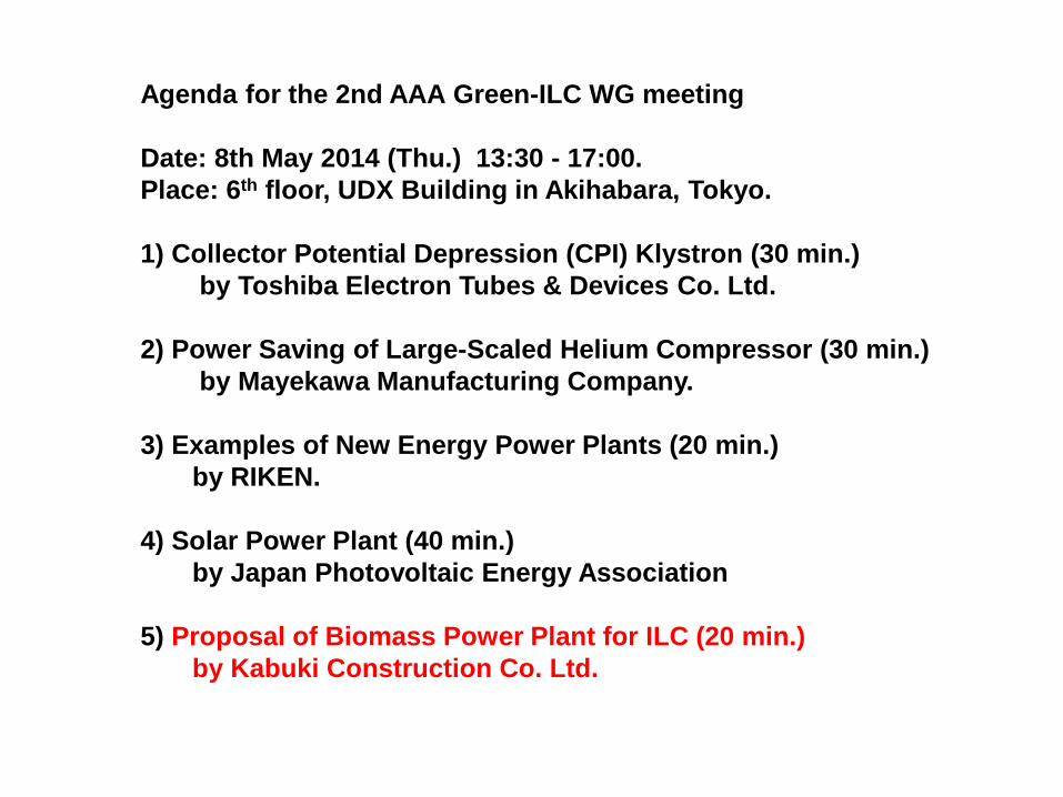
Agenda for the 2nd AAA Green-ILC WG meeting
Date: 8th May 2014 (Thu.) 13:30 - 17:00.Place: 6th floor, UDX Building in Akihabara, Tokyo.
1) Collector Potential Depression (CPI) Klystron (30 min.) by Toshiba Electron Tubes & Devices Co. Ltd.
2) Power Saving of Large-Scaled Helium Compressor (30 min.) by Mayekawa Manufacturing Company.
3) Examples of New Energy Power Plants (20 min.) by RIKEN.
4) Solar Power Plant (40 min.) by Japan Photovoltaic Energy Association
5) Proposal of Biomass Power Plant for ILC (20 min.) by Kabuki Construction Co. Ltd.

Agenda for the 3rd AAA Green-ILC WG meeting
Date: 1st July 2014 (Tue.) 13:30 - 17:00.Place: 6th floor, UDX Building in Akihabara, Tokyo.
1) Energy Recovery at Beam Dump at ILC (20 min.) by J. Fujimoto (KEK).
2) Tests of Collector Potential Depression (CPD) Klystron (30 min.) by K. Watanabe (KEK).
3) Drag Reduction (DR) Additive for Cooling Water (30 min.) by Shin Nippon Air Technologies Co. Ltd.
4) Examples of New Energy Power Plants (30 min.) by RIKEN.

Agenda for the 2nd AAA Green-ILC WG meeting
Date: 8th May 2014 (Thu.) 13:30 - 17:00.Place: 6th floor, UDX Building in Akihabara, Tokyo.
1) Collector Potential Depression (CPI) Klystron (30 min.) by Toshiba Electron Tubes & Devices Co. Ltd.
2) Power Saving of Large-Scaled Helium Compressor (30 min.) by Mayekawa Manufacturing Company.
3) Examples of New Energy Power Plants (20 min.) by RIKEN.
4) Solar Power Plant (40 min.) by Japan Photovoltaic Energy Association
5) Proposal of Biomass Power Plant for ILC (20 min.) by Kabuki Construction Co. Ltd.

How to Improve RF Efficiency
R&D of CPD (Collector Potential Depression) KlystronCPD is an energy-saving scheme that recovers the kinetic energy of the spent electrons after generating rf power.
Conventional
collector
Schematic diagram of CPD
collector

Agenda for the 3rd AAA Green-ILC WG meeting
Date: 1st July 2014 (Tue.) 13:30 - 17:00.Place: 6th floor, UDX Building in Akihabara, Tokyo.
1) Energy Recovery at Beam Dump at ILC (20 min.) by J. Fujimoto (KEK).
2) Tests of Collector Potential Depression (CPD) Klystron (30 min.) by K. Watanabe (KEK).
3) Drag Reduction (DR) Additive for Cooling Water (30 min.) by Shin Nippon Air Technologies Co. Ltd.
4) Examples of New Energy Power Plants (30 min.) by RIKEN.

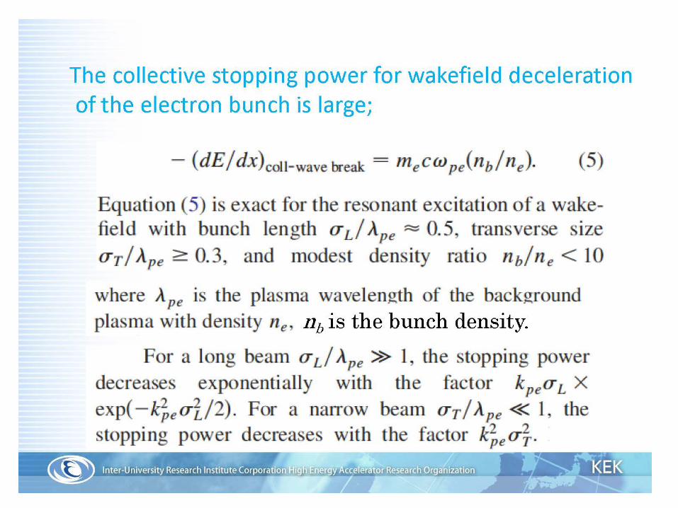
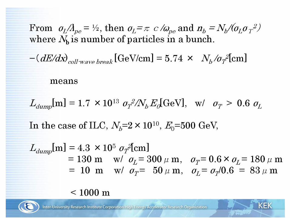
Collective deceleration for compact beam dump
Bethe-Bloch formula for stopping power in material
There was a progress.

~60 perticipants
G. Mourou (Polytech)T. Tajima (UCI)B. Holzer (CERN)

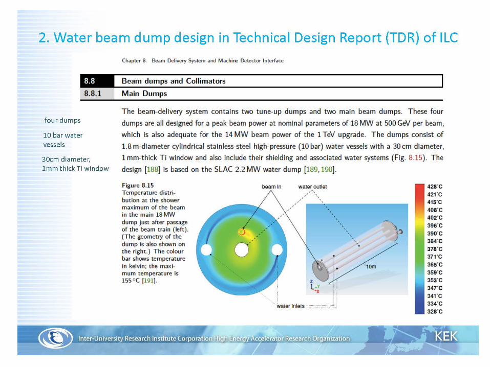
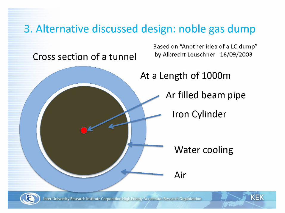

Pros/consWater dump Gas dump
length 10 m 1000 m
Window pressure 10 bar static 1 bar static
Window diameter 30 cm 8 cm
Hydrogen gas producing
Several liter/sec @ 20 MW
no
Tritium production 300 TBq 30 TBq ( in Iron)
Component Activity 1.2 mSv/h ~ 1 … 10 mSv/h


Agenda for the 3rd AAA Green-ILC WG meeting
Date: 1st July 2014 (Tue.) 13:30 - 17:00.Place: 6th floor, UDX Building in Akihabara, Tokyo.
1) Energy Recovery at Beam Dump at ILC (20 min.) by J. Fujimoto (KEK).
2) Tests of Collector Potential Depression (CPD) Klystron (30 min.) by K. Watanabe (KEK).
3) Drag Reduction (DR) Additive for Cooling Water (30 min.) by Shin Nippon Air Technologies Co. Ltd.
4) Examples of New Energy Power Plants (30 min.) by RIKEN.

Drag Reduction (DR) Additive in Cooling Water
Adding DR additive
Large energy loss in the cooling water flow
Effect of DR additive in cooling water
Small energy loss in the cooling water flow
Slide by Shin Nippon Air Technologies Co. Lts.

Agenda for the 2nd AAA Green-ILC WG meeting
Date: 8th May 2014 (Thu.) 13:30 - 17:00.Place: 6th floor, UDX Building in Akihabara, Tokyo.
1) Collector Potential Depression (CPI) Klystron (30 min.) by Toshiba Electron Tubes & Devices Co. Ltd.
2) Power Saving of Large-Scaled Helium Compressor (30 min.) by Mayekawa Manufacturing Company.
3) Examples of New Energy Power Plants (20 min.) by RIKEN.
4) Solar Power Plant (40 min.) by Japan Photovoltaic Energy Association
5) Proposal of Biomass Power Plant for ILC (20 min.) by Kabuki Construction Co. Ltd.

Low stage Compressor
Heat source from the helium compressor
High stage compressor
Oil cooler
Oil cooler
Inter cooler
After cooler
Heat source
Chilled water
Cooling water
Oil separator
Adsorption chiller
AdRef
50%
50% Power input100%
3%
47%
47%
42%
3%
2.5%5%
After313K ≒358K
Before313K ≒363K
Temperature balance of the oil cooler
≒363K

300K
4.25MW(100%)
310K
80K
Conventional cycle
18kW
Waste Heat(95%)
Waste Heat(5%)
270K
3.97MW(93%)
310K
80K
18kW
New cycle with AdRef
280K4kW(0.1%)
ILC⊿3MW
(45.81→ 42.79MW)
New refrigeration cycle with AdRef
280K270K Compact cold box
& HEX
Waste Heat(5%)
Low suction temp. →small compressor→small power consumption
AdRef
Heat Source
Waste Heat(93%)

Agenda for the 2nd AAA Green-ILC WG meeting
Date: 8th May 2014 (Thu.) 13:30 - 17:00.Place: 6th floor, UDX Building in Akihabara, Tokyo.
1) Collector Potential Depression (CPI) Klystron (30 min.) by Toshiba Electron Tubes & Devices Co. Ltd.
2) Power Saving of Large-Scaled Helium Compressor (30 min.) by Mayekawa Manufacturing Company.
3) Examples of New Energy Power Plants (20 min.) by RIKEN.
4) Solar Power Plant (40 min.) by Japan Photovoltaic Energy Association
5) Proposal of Biomass Power Plant for ILC (20 min.) by Kabuki Construction Co. Ltd.

CGS(Co-Generation System) at RIKEN
6500 kW- Power ClassGas Turbine Cogenerationwith variable thermal & electrical power
Ambient Air Wasteheatboiler
C TG 400USRT×5360USRTx 2Absorption Chiller
Intake Air Cooler
6250 kWElectrical Output
10.3t/h Steam
190 USRT
34 ℃
1618 Nm3/h Fuel(Natural Gas)2.5 t/hInjection
7℃Chiller Water
2530 USRT
12℃
ExhaustGas
15 ℃
Chiller Water for Air Cooler
【Rated Performances at 15℃】・Output Power 6250kW
・Fuel Consumption 1618 Nm3/h
・Steam Output 12.8 t/h・Electrical Efficiency 32.1%・Thermal Recovery Ratio 32.3%・Total Efficiency 64.4%
・NOx Emission 32.3ppm(O2 0%)
・Sound Level 70db(1m)
Burner1100℃

Agenda for the 2nd AAA Green-ILC WG meeting
Date: 8th May 2014 (Thu.) 13:30 - 17:00.Place: 6th floor, UDX Building in Akihabara, Tokyo.
1) Collector Potential Depression (CPI) Klystron (30 min.) by Toshiba Electron Tubes & Devices Co. Ltd.
2) Power Saving of Large-Scaled Helium Compressor (30 min.) by Mayekawa Manufacturing Company.
3) Examples of New Energy Power Plants (20 min.) by RIKEN.
4) Solar Power Plant (40 min.) by Japan Photovoltaic Energy Association
5) Proposal of Biomass Power Plant for ILC (20 min.) by Kabuki Construction Co. Ltd.

Solar power: >50 GW at 2030 in Japan
Smart Country by Smart GRIG
Agenda for the 2nd AAA Green-ILC WG meeting
Date: 8th May 2014 (Thu.) 13:30 - 17:00.Place: 6th floor, UDX Building in Akihabara, Tokyo.
1) Collector Potential Depression (CPI) Klystron (30 min.) by Toshiba Electron Tubes & Devices Co. Ltd.
2) Power Saving of Large-Scaled Helium Compressor (30 min.) by Mayekawa Manufacturing Company.
3) Examples of New Energy Power Plants (20 min.) by RIKEN.
4) Solar Power Plant (40 min.) by Japan Photovoltaic Energy Association
5) Proposal of Biomass Power Plant for ILC (20 min.) by Kabuki Construction Co. Ltd.

Conceptual Biomass Town around ILC
出典:土浦市バイオマスタウン構想書
❑ 有機性廃棄物利用バイオマス発電Biomass Power Plant using Organic Waste
Lake
Organic Waste Process Machine
Residences
Farming
Farming(Animals) Farming
(Fruits)
Lumber / wood industries
Biomass wasteUnutilized BiomassPower / Products
FactoriesStoresTraffic
Offices
Biomass Diesel Fuel Factory
Compost Factory
MethaneFermentFactory
Recycling Factory
Park

Summary• The 1st meeting for the Green-ILC WG of AAA was held on 25th
February 2014 to launch the Green-ILC-AAA activity.• The series of Green-ILC-AAA WG meetings were held since then, and
various realistic technologies of energy-saving for ILC were proposed and discussed by industries and scientists in the meetings.
• There was a progress in the study on energy recovery at beam dump.
• The energy-saving technologies discussed in the Green-ILC-AAA meetings are ranging from the components, sub-system, ILC-system, and to ILC-city.
• Proposed items for Green-ILC energy-saving technologies will be summarized and written in the report in English under the framework of AAA in the beginning or middle of year 2016.

Green-ILC

Backup slides

Present Status of R&D
R&D Schedule2013.3: Modification of an existing klystron to CPD klystron (already done)
2014.3: until then, preparation and commissioning of the test station~2014: Verification of klystron operation without CPD~2015: Measurement of rf leakage from the gap between the body column and the collector (with no CPD voltage applied)
Measurement of induced pulse voltage on the collector with CPD~2017: Test of rectification by Marx circuit
Integration test of the proof-of-principle of CPD operation
Recycled components•electron gun•input cavity•intemediatecavities
Newly fabricated components•collector•ceramic insulator•output cavity•output coupler
Targetproof-of-principle of CPD in the unsaturatedregion (a maximum rf power of 500 kW)using a KEKB 1.2MW-klystron
Goal : 80 % efficiency

Agenda for the 3rd AAA Green-ILC WG meeting
Date: 1st July 2014 (Tue.) 13:30 - 17:00.Place: 6th floor, UDX Building in Akihabara, Tokyo.
1) Energy Recovery at Beam Dump at ILC (20 min.) by J. Fujimoto (KEK).
2) Tests of Collector Potential Depression (CPD) Klystron (30 min.) by K. Watanabe (KEK).
3) Drag Reduction (DR) Additive for Cooling Water (30 min.) by Shin Nippon Air Technologies Co. Ltd.
4) Examples of New Energy Power Plants (30 min.) by RIKEN.

Preparation of CPD Klystron test at KEK
CPD Klystron
Collector Potential Depression (CPD) Klystron
Dummy resister
DC 90kV oscillator circuit for output
Capacitor for circuit (only one capacitor is delivered)
DC 25kV oscillator circuit for input

Multi(6) – Beam Klystron (MBK) for 26 Cavities for ILC
Frequency 1.3 GHzPeak power 10 MWPulse width 1.6 msRep. rate 5 HzAverage power 78 kWEfficiency 65 %Gain 47dBBW (- 1dB) 3 MHzVoltage 120 kVCurrent 140 ALifetime 40,000 h
The design goal is to achieve 10 MW peak power with 65 % efficiency at 1.5 ms pulse length at 10 Hz repetition rates.
MBK has 6 low-perveance beams operated at low voltage of 115 kV for 10 MW to enable a higher efficiency than a single-beam klystron.

Simplified Schematic Concept
Potential denotes the electron potential energy, eV. Forsimplicity, input and intermediate cavities are omitted hereand the anode potential is set to zero.
Pote
ntia
l & E
lect
ron
Ener
gy
Cathode
Anode Output cavity Collect
or
RFPotential in the Klystron
Electron Energy
With CPD
E0
Ec
CPD gap
Uk
Uc
E1
Pote
ntia
l & E
lect
ron
Ener
gy
Cathode
Anode Output cavity Collect
or
RF
Potential in the Klystron Electron
Energy
Without CPD
E0
Uk
Uc
Ec
E1
Efficiency of RF Conversion (40-50) %Heat Loss
Beam DecelerationEnergy Recovery/Reuse

(I) Energy spreadThe spent electron beam has large energy spread through electromagnetic
interaction in the cavities. Therefore, the collector potential cannot be increasedbeyond the lower limit of energy distribution of the spent electron beam, otherwisebackward electrons hit the cavities or the gun, and then deteriorate the klystronperformance.
Issues must be addressed for CPD Klystron
Saturated: 1 MW out
Unsaturated: 200 kW out
E0 = 90keV E0 = 90keV
(II) Pulse-to-DC conversionThe spent electron beam is longitudinally bunched, sothat pulsed voltage is induced on the collector. Anadequate pulse-to-DC converter has to be implemented.
(III) RF LeakageCPD klystron has to be equipped with an insulator
between the collector and the body column in order toapply CPD voltage to the collector. Thus, it would bepossible for the CPD klystron to leak rf power out moreor less from the insulator. Ceramic Insulator
Output Coupler Collector

Resister in straight pipes
Resister in joints
+Resister in
active components
Before adding DR additive
Resister
Resister in joints
+Resister in
active components
After adding DR additive
DR effect reduction50 – 80 % of
resister in straight pipes is reduced
※Flow rate 1.5~2.0m/s
Drag Reduction (DR) Additive in Cooling Water
Effect of DR additive in cooling water
Gross pump head
Slide by Shin Nippon Air Technologies Co. Lts.

48
Adsorption chiller “AdRef”Environmentally Friendly Chiller.Features1. No CFCs, HCFCs used.
Water (H2O) is used as refrigerant.2. Low temperature heat source.
As low as 65 C3. Super Energy Saving
Only a few HP necessary4. Easy maintenance
Very few moving parts used.5. Safe
No pressure piping or refrigerant

49
Evaporator Condenser
Adsorber
A B
Waterpump
Vapor H2O is removed from adsorber“B” by heating with warm water, andcondensed in the condenser by the coolof cooling water.
Heatsource
Coolingwater
Coolingwater
Chilledwater
Liquid water goes to theevaporator.
The adsorber “A” adsorb vaporH2O by cool of cooling water.Then the liquid H2O in theevaporator evaporates, and thelatent heat cool down the chilledwater.
Vapor H2O
Adsorption chiller “AdRef”
Adsorber

50
A B
Heating/Cooling of adsorber A/B isswitched periodically.
Adsorption chiller “AdRef”
Evaporator Condenser
Adsorber
Waterpump
Vapor H2O is removed from adsorber“B” by heating with warm water, andcondensed in the condenser by the coolof cooling water.
Heatsource
Coolingwater
Coolingwater
Chilledwater
The adsorber “A” adsorb vaporH2O by cool of cooling water.Then the liquid H2O in theevaporator evaporates, and thelatent heat cool down the chilledwater.
Vapor H2O
Adsorber Liquid water goes to theevaporator.

Absorption refrigerator (chiller)(from Wikipedia, the free encyclopedia)
• An absorption refrigerator is a refrigerator that uses a heat source (e.g., solar, kerosene-fueled flame, waste heat from factories or district heating systems) to provide the energy needed to drive the cooling system.
• In the early years of the twentieth century, the vapor absorption cycle using water-ammonia systems was popular and widely used, but after the development of the vapor compression cycle it lost much of its importance because of its low coefficient of performance(about one fifth of that of the vapor compression cycle). Nowadays, the vapor absorption cycle is used only where waste heat is available or where heat is derived from solar collectors. Absorption refrigerators are a popular alternative to regular compressor refrigerators where electricity is unreliable, costly, or unavailable, where noise from the compressor is problematic, or where surplus heat is available (e.g., from turbine exhausts or industrial processes, or from solar plants).

Scheme of the water system for the water beam dump
• 70oC hot water can be obtained.
• Energy recovery
TESLA

ILC parameters

ILC parameters

CGS (Go-Generation System) at RIKEN• 6.5 MW + 2720 USRT• 1Hz (20msec) power switch
for blackout.• Efficiency:68%, as of June
2010.
• G:7MVA. 6.6kV. 50Hz.• T :1100℃/480℃. 14000rpm. 6.6MW /12℃.• B :480℃/160℃. 1.6MPa(210℃)12.5t/h• C :400 USRT x 5 + 360 USRT x 2, 7℃ at outlet (1 USRT=3.52kW. )

52SRB1 7 6 5 4 3 2 1
VCB8
CGS母線負荷
G
制御電源
相ンサー
He冷凍機
冷却系 加速器棟
GT用補機
6.6MWGTG
52SRB2
Big-RIPS超伝導
電磁石電源
SRC同左
真空系
52RG1
614kVA602kW
756kVA613kW
1200kVA1070kW
757kVA645kW
776.8kVA209KW
1000kVA574KW
Spare
0kvar
クトル9MVA
Power Line Circuit
CGS Load
Cooling Water
Vac. Acc.Building
Acc.Control
He Refrig.
SRC Magnet
Big-RIPSSRF
Magnet
GT Spare

Solar Power Production / Top 6 Countries
Integrated Installation (2012) Installation per Year (2012)
German
Japan
German German
JapanJapan
MW MW/Y Japan
German

Projection of Solar Power Production in Japan by IEA
Inte
grat
ed S
olar
Pow
er P
rodu
ctio
n in
Jap
an (G
W)
Year+2000
Projection done in 2013(WEO2013)
Projection done in 2012(WEO2012)

Weekly Production in Germany (2012)

❑ Estimate of Biomass Electric Power
ILC (Tunnel Heat Waste)
Water content 15 – 90 %
Water content 15 %
Burned Ash
Recovered Heat
Heat
Recycling Products
Regional usage: FarmingHospitalTourism・・・
Steam
Estimate of Electric PowerAssuming the efficiency of 10~20%
Kitakami Site 58,104 kW×10 ~20% = 6,000~10,000kWSefuri Site 43,280 kW×10 ~20% = 5,000~10,000kW
Direct Burning
Electric GenerationDrying
Various Biomass