energy storage systems - fortress power
TRANSCRIPT

Fortress PowerEnergy Storage Systems

Part One: DesignMatt Moore – Technical Support
at Fortress Power

▪ PROJECT ASSESSMENT
▪ FORTRESS POWER ENERGY STORAGE SIZING TOOL
▪ SELF-MANAGING CRITICAL LOAD PANEL
▪ HOME OWNER REPORT
TOPICS
▪ PRODUCT SPECIFICATION

FortressPower Lithium BatterySize
Total Energy (kWh)
Max. Charge Current (Continuous) [A]
Max. Discharge Current (Continuous) [A]
Max. Pulse Current (for 10 sec) [A]
Capacity [Ah]
Voltage [V]
Charging Temperature [F]
Storage Temperature [F]
Dimension [H xW x D, inch]
Weight [lbs]
Depth of Discharge
Warranty
LFP- 10 LFP- 15
10.24
100
100
200
200
48
33 x 16.4 x 9.4
286
15.36
100
100
200
200
48
33 x 16.6 x 13.4
429
-4 to 140
-4 to 131
100%
10 years
SAFE • AFFORDABLE • EASY TO INSTALL
FORTRESS POWER LITHIUM ION PHOSPHATE BATTERY
FO
RT
RE
SS
PO
WE
R B
AT
TE
RY
SY
ST
EM
S

DARFON H5001 HYBRID INVERTERP
RO
JEC
T A
SS
ES
SM
EN
T
PV Input Grid Input
Up to 6.5kW Up to 5kW
2 independent MPPTs Auto-transfer Relay Rating: 48A
Max. 13A per string 20ms Typical Transfer Time
Voc: 120~500V; Mppt: 250-430V 240 Split Phase; 50/60 Hz
Grid Output Critical Load
0 to 24A Feed-in Current 5kW Cont. Output
L-L: 211 to 264VAC ± 3.0V5.5/6.5/7.5kW Surge power at (40/5/1sec)
59.4 to 60.4Hz ± .05 Hz 0 - 21A Output Current
Rule 21 Compliant Voltage 240 2P; 50/60 Hz

PROJECT ASSESSMENTP
RO
JEC
T A
SS
ES
SM
EN
T
• Assess PV Array
• Location – space – tilt – azimuth
• Critical Load Circuits
• What is essential to be backed up
• Non-essentials to be backed up
• Customer Expectations
• Hours of operation during grid outages

PV ARRAY SIZING TOOLF
OR
TR
ES
S P
OW
ER
EN
ER
GY
SIZ
ING
TO
OL
1. Sizing PV array
2. Estimate average daily PV production
3. Selecting critical load circuits
4. Calculating daily usage of critical load panel
5. Selecting battery bank size
How to size the Energy Storage System
Fortress Power Energy Storage Sizing Tool
Category Item Quantity Starting Watts Running Watts Hours/Day Watthours/Day
1 Essential Incandescent Light Bulb-60 Watt 3 180 180 6 3240
2 Essential LED Light Bulb-60 Watt Equivalent 6 48 48 8 2304
3 Essential Refrigerator/Freezer-Energy Star 1 1200 200 8 1600
4 Essential Sump Pump-1/3 HP 1 1300 800 0 0
5 Essential Water Well Pump-1/3 HP 1 1400 750 3 2250
6 Kitchen Microwave Oven-800 Watts 1 1300 1300 0 0
7 Kitchen Slow Cooker 1 270 270 4 1080
8 Personal Electronics TV-Flat Screen-46" 1 190 190 4 760
9 Personal Electronics Cell Phone Charger 2 50 50 2 200
10 Personal Electronics Computer-Laptop 2 500 500 1 1000
Totals 6438 4288 12434
Inverter Type Watthours/Day
Darfon H5001 62 712
The above table is for estimating the size of the batteries needed for your energy storage system. Actual usage may vary.
* Large inductive loads (well pumps, sump pumps, pool pumps, etc.) require a larger surge current (watts) when they power on before they eventually slow down to the
running wattage. The Fortress Power Sizing Tool provides estimated surge current values, however since large inductive loads vary greatly it is the user’s responsibility to
ensure the correct values for the specific equipment are entered into the sizing tool. Pump ratings can be found on the name plate of the device (see the sample name
plate image below). Use the LRA rating (locked rotor amps) to find the max value/worst case scenario then multiply these values (usually expressed in amps) by the
voltage rating of the device - either 120VAC or 240VAC. In the example below 15A x 240 VAC = 3,600 surge watts.
Additional Household Electrical Items
with Starting & Running Watts
Surge Power
Watts Available Watts Available
Running Watts

FO
RT
RE
SS
PO
WE
R E
NE
RG
Y S
IZIN
G T
OO
LHOME OWNER REPORT

HOME OWNER REPORTF
OR
TR
ES
S P
OW
ER
EN
ER
GY
SIZ
ING
TO
OL

CRITICAL LOAD PANELF
OR
TR
ES
S P
OW
ER
EN
ER
GY
SIZ
ING
TO
OL
Maximum single-pole circuits: 10
Maximum double-pole circuits: 5
Maximum running wattage: 7.5 kW
Self manage between grid and back-up

Part Two: InstallationBryan Whitton – Product Manager at
Darfon

First StepYour H5001 will come in a cardboard box. On the box will be alabel with a description and the serial number. You should noteboth to make sure it is the right part and that you have the serialnumber for warranty purposes.

Removing the H5001• Remove the accessories.• Remove cardboard inserts and the H5001 from the plastic bag.• Inspect for any possible damages.

H5001 Distribution Box
All the I/O happens here. Plenty of room to work with, easy to install and configure.
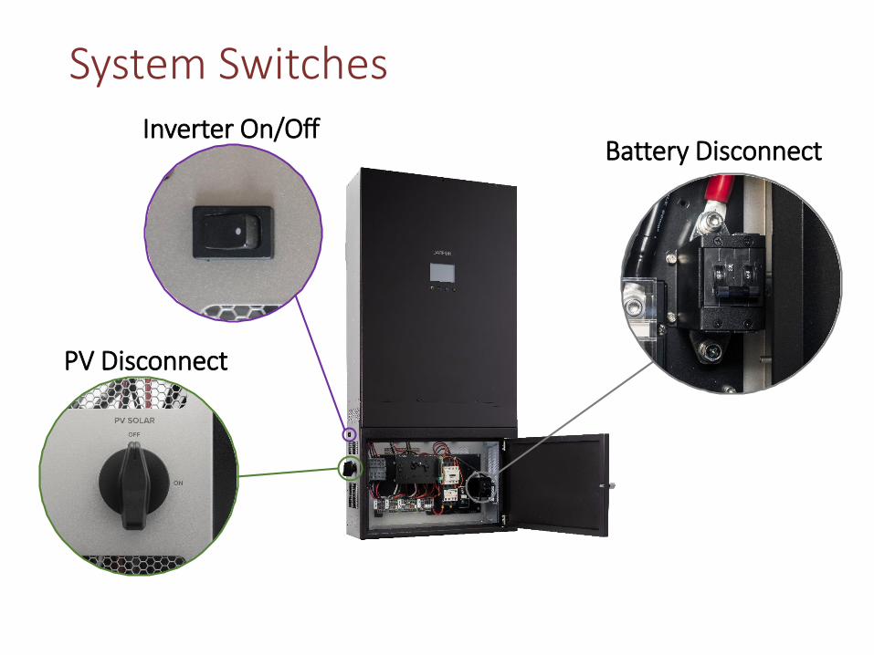
System Switches
Battery Disconnect
PV Disconnect
Inverter On/Off

Concentric KnockoutsLocated along the right, left and bottom of the distribution box
Clean install!
Typically for PV Connections
Typically for AC & Generator Connections
Right Side Access

Concentric Knockouts
Battery Connection:
Right below the batteryterminals and shutoff switchis a concentric knockout for1”, 1.25” and 1.5”connectors. You will need2/0 conductors for thebattery.

How it mountsThe hanger bracket it is designed to bolt to the wall and hang inverter.
I use Unistrut on the top and bottom. The H5001 simply hangs on the bracket. Be sure to bolt directly into studs.
The bottom inverter bracket bolts directly to the Unistrut.

Quick Disconnect Terminals

Installing/Removing Conductors
Installing Conductors
• Push a small screwdriver into the release access.
• Insert the wire and remove the screwdriver.
Removing Conductors
• Push the screwdriver into the release access and pull the wire out.
Note: Terminals use high tension springs that require a strong push to get the contact to open.

PV Conductors
• Two MPPTs in the PV inverter (It doesn’t matter which string inputs you use if you only have one string)
• Maximum wire size is #10 AWG.
*Now is a good time to check the PV voltage and polarity*

AC Grid-Tie Conductors
• Make sure the grid ispowered down when you areconnecting the wires
• We can handle #8 AWG wirein these connectors
• It takes 2 minutes to do.
• There is a fair amount ofroom in the distribution boxto work with so leave a littleextra wire length to make iteven easier.
*Now is a good time to check the AC voltages*

Critical Load Panel
• Same as the Grid-Tie butan extra set of inputs.
• Double the inputs. Again,it gives you flexibility.Occasionally you may wantto split the loads such aslights and receptacles orsomething along thoselines. This simply givesflexibility.

Landing the Battery Conductors
Step 4. Clip the finger guardback over the negativeconnector for safety.
Step 1. Switch off the Battery.Step 2. Pull the clear fingershield off from the negativeconnector.
Step 3. Attach the negative cableto the negative connector andthe positive cable to the positiveconnector. Use a 5/16” lug.
Note: Keep the cables as short as possible.

Finished!
You have successfully installed and wired an H5001inverter. At this point you will need to set the date,time and mode of operation but that is in the nextsession.

THANK YOU – Contact Us!
Matt Moore
Technical Support
(877) 497- 6937
www.fortresspower.com
Bryan Whitton
Product Manager
(650) 815-7121
www.darfon.com