energy wise wiring diagrams - minnesota valley … wise ® wiring diagrams for technical questions,...
TRANSCRIPT

Energy Wise®Wiring Diagrams
For technical questions, call952-492-8330
To schedule off peakmeter installation, call
Debi Nelson952-492-8231

ENERGY WISE® CONTROLLABLE LOADS
Water Heaters – All water heaters are controlled as storage or interruptible. This is determined when there are three or less people who live at the residence, when the structure is less than three thousand square feet, or if the system is designed for storage. All others should be interruptible. The use of multiple water heaters will require two circuits controlled with a separate relay, or unless the manufacturer has provided wiring to interlock the two.
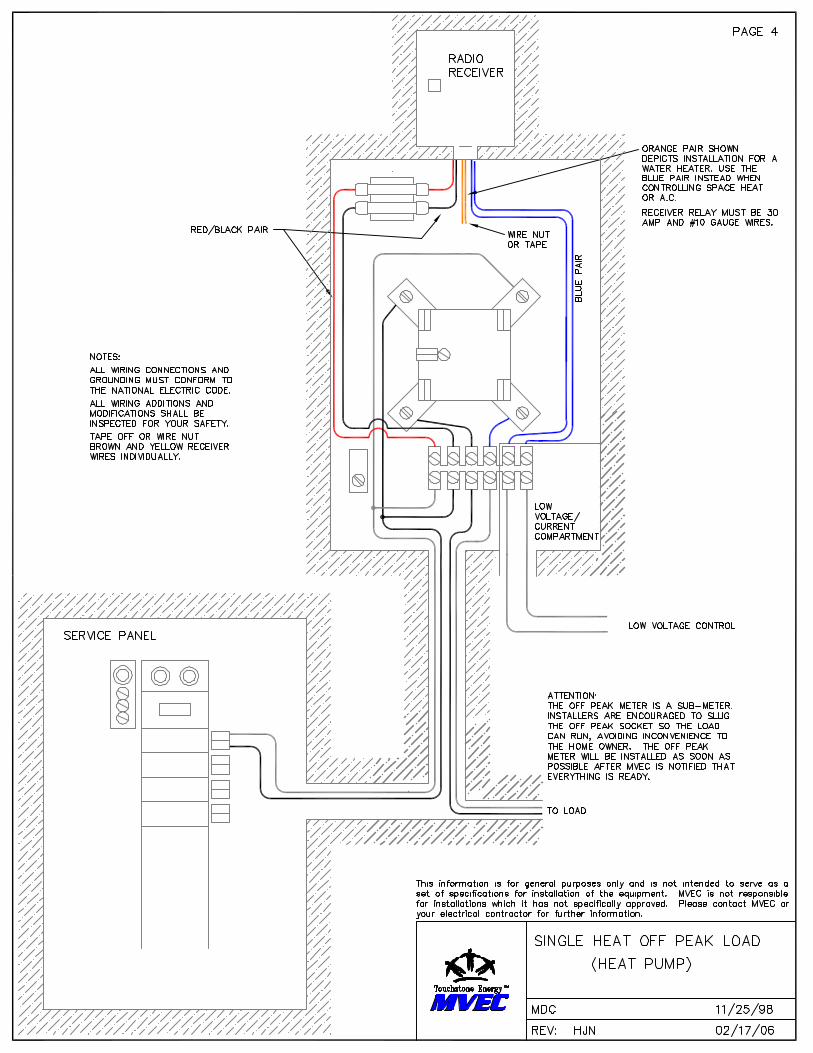
Heat Pumps and Air Conditioners are always controlled with the 24-volt system. Refer to the manufacturer or installing HVAC contractor on where you should control. When two-stage units are installed, it may be necessary to control both stages with a double pole relay. All low voltage connections are to be installed in junction boxes or inside equipment.
Plenum Heaters are inserts installed in the plenum of a furnace that will heat electrically and switch over to the back-up heat when being controlled. It is installed the same direction as the coil and is normally controlled in the 24-volt system.
Electric Heat – Baseboard, cove or wall heaters are normally controlled with line voltage using a relay rated for the purpose. When there are more than two circuits to be controlled, a Peak Interrupter is highly recommended.
Hot Tubs – Only indoor units qualify due to the possibility of freeze damage during the timesit will be controlled. Please refer to manufacturer’s instructions for control applications.
Boiler – In-floor heat and dual heat boilers are the most common and require special consideration when looking to control. Most will be controlled with the low voltage system. In-floor heat could be controlled by low voltage or line voltage with the circulating pump circuit depending on the situation.

Energy Wise ®Equipment List
2010
Rec
eive
r
CT
12V
DC
Rel
ay/D
PP
DT
240
VA
CR
elay
/Bla
ck
Pag
e
Heat on 1 Circuit x 3
AC & WH x x 6
2 AC Circuits/Low Voltage Control x x x 6
Heat on 1 Circuit & WH x x 6, 8
Heat on 2 Circuits x x 6, 8
Heat on 2 Circuits & WH x x 5, 6, 9Heat on 5-6Circuits &WH/AC Optional x x 6
Add single meter socket if member does not have a double meter socketGet technical advice if SWH capacity will exceed 170 gallonsGet technical advice if any circuit exceeds 30 ampsGet technical advice if this chart does not cover the system being installedAll recommendations presume installation of a Cannon receiver

INSTALLATION SPECIFICATIONS
1. The meter and receiver must be mounted outside and always vertically.
2. Meters installed since 1992 are normally double meter sockets that are attached to the house or garage. All others will use Electro Industries EE5062A
Single Meter socket in combination with a single main meter on house or when the main meter is on the pole. These meter sockets are available from MVEC.
3. When a current transformer is used for metering, the member or contractor shall supply 2x12x4 junction box to mount the CT and relays. When nipling to your service panel, size generous to allow for future loads. All controlled loads “A” phase wires from the panel breakers must run through the CT one direction and “B” phase wires from panel breakers must run through the CT the opposite direction. Only controlled loads are to be wired through the CT. From CT terminals, two # 12 AWG stranded wires need to run to the meter socket and terminate at the upper left and lower left lugs.
4. When current transformer metering is used, Energy Wise meter potential must always
be fused together with the Energy Wise controller. 240 volt power whenever possible will be supplied from the main meter socket load side lugs. Use crimp –on AL/CU barrels when appropriate. And when a single meter is used, an uninterruptible circuit such as a water heater circuit should be used. The meter potential terminals on a CT meter socket are middle left terminal and upper right lug.
5. Energy wise controllers use a 30amp relay with orange wires to control the water
Heater circuit and 5amp or 30amp relay with blue wires to control heating loads, when controlling various heating loads refer to the appropriate wiring diagrams. If further questions arise, please contact MVEC.
6. All electric heat that is under control must be hard wired and all backup or standby
heat must be permanently installed and is able to be operated automatically.

Can I use a standard 100 amp socket
from a wholesale electrical supplier for
an off-peak installation?
The answer is NO: You must use the socket provided
by MVEC because of the fusing requirements for the
receiver. Standard sockets don’t come equipped with the
fuses that are placed in the socket for protection of the
receiver.
Can I break line voltage
to a central air unit?
The answer is YES: Although we don’t suggest this
type of installation, if there is no other possible means of
breaking the low voltage to the unit, it is allowed to break
the 240Volt for control. Some of the newer units will not
allow this type of installation as it extends the control
time due to time outs within the unit. Make sure you
contact the manufacturer to be sure. If it’s wrong,
we will not put the meter in.
Can I use the orange pair for
something other than water heat?
The answer is YES: We try to keep the orange pair for
water heat as much as possible, but if the homeowner
chooses not to utilize the water heater program, the
orange pair can be utilized to control other forms of load.
It would be recommended to utilize this as a secondary
option to the blue pair preferably for the heat type of
loads or a second central air.
Can I control a 30 amp load
with an ice cube relay?
The answer is NO: The ice cube relays are intended to
be used for a low voltage type of installation only.
They’re normally utilized when you have multiple loads
to be controlled from the blue pair. The ice cube relay
can also be utilized for small resistive heat loads
(circulation pumps, and small wall heaters.)
When do I need to use a black relay
and how are they controlled?
The black relays are used on multiple line voltagecontrolled loads where any one load does not exceed
30 amps. The control circuit comes from paralleling the
line voltage from one of the loads passing one leg
through the blue pair and onto the coil of the relay.
Why do I need to install the
ice cube relay in the receiver?
The answer is YOU DON’T: Sometimes it’s easier to
install the ice cube relay in a remote location closer to
the source. In this case, the ice cube relay should be
mounted inside the CT box. You will need to extend the
control wiring inside the relay (22 awg wires controlling
the blue pair relay) down to the CT box.
Wiring 101
Your Top 15 questions about
Energy Wise®/off peak installations
by Mike DietzFor questions, call our hotline at
952.492.8330
1.
2.
3.
4.
5.
6.

What should I do with the receiver on
a peak shave central air unit if the
member adds additional off-peak loads?
This answer is never easy! It is in MVEC’s best interest
to always try to limit each location to one receiver per
metering point. If there is any possible way to remove
the receiver at the central air and combine the control
points at the new receiver location, we want everyone to
try and accomplish that. If it’s going to affect the integrity
of the system by moving it, then leave the receiver in its
location and meter the load through the CT at the new
metering point. If this type of installation is needed, this
should be authorized by MVEC before doing so.
When is it allowed to add
a second off-peak meter?
If you have a facility (detached garage or outbuilding)
that has its own main panel fed from an existing
panel that currently has off peak, it’s allowed to install
a second meter at the new location of the service panel.
If there is absolutely no possible way of getting back to
the existing off peak equipment, there maybe an option
for adding a second off peak meter to accommodate
those loads. These types of installations need to be
discussed with MVEC before installing.
I’ve seen at other cooperatives they
meter the whole off-peak panel.
MVEC DOES allow this type of installation.Remember: if doing this type of installation, be sure all
loads in this service panel need to be controlled for off
peak. You will need to purchase a single socket and
install that before the service panel. In these types of
installations, the panels still need to be fed from the load
side of the general service meter. In NO case can the
off-peak meter be the only meter at a service location.
Could I be billed from MVEC
if the equipment was not
installed correctly?
The answer is YES: We started this a few years ago.
We will bill the member if you schedule an appointment
for install, we make a trip out there, and the equipment is
not ready. Make sure all equipment is operational and
ready to be controlled when we get there.
Does the CT need to be grounded?
The answer is YES: Make sure the CT is always
grounded on one terminal upon installation.
Can I break a heat pump with
high voltage? Can I line meter the
heat pump if it’s my only load?
The first answer is NO. The second answer is YES:All heat pumps need to be broke with some type of low
voltage method. A heat pump - if it’s the only load on the
system - can be line metered.
I’m installing a wind turbine or solar
panels to my existing service. Where
do I locate the off-peak meter?
At this time MVEC DOES NOT allow a member to be
on this rate with off-peak equipment. The meter will need
to be removed by MVEC and the cover shunted. If you
are installing some type of renewable energy, please
have the member contact MVEC before getting started.
Is the receiver always the problem
when out on a service call?
This is a myth: It’s usually not the problem when we get
there. Be sure you have a good idea of what’s wrong
before you cycle power to the equipment. The receivers
have a built-in timeout that we utilize for system restore
during outage situations. Remember, some of our equip-
ment is being powered by the circuit breakers or discon-
nects of the equipment you’re working on. This timeout
is usually around 15 minutes before it will restore. Out of
the 14,000 receivers that we have on our system, very
few fail per year so check the lights before powering
down and be willing to wait when you power it back up.
Is there a way to test the receiver
to see if it’s controlling correctly?
YES: Inside the receiver on the door side there is a little
black button that you can press to control the relays.
This will allow you to test the relays to make sure all is
functioning correctly. If you
have any question on where
this is, please be sure to ask.
If you have questions, call our hotline at 952.492.8330
7.
8.
9.
10.
12.
13.
14.
15.
11.