energymax-usb/rs user manual - content.coherent.com
TRANSCRIPT

User Manual
EnergyMax -USB/RSSensor System
TM

User ManualEnergyMax-USB/RSSensor System
27650 SW 95th Ave.Wilsonville, OR 97070

EnergyMax-USB/RS User Manual
This document is copyrighted with all rights reserved. Under the copyrightlaws, this document may not be copied in whole or in part or reproduced inany other media without the express written permission of Coherent, Inc.Permitted copies must carry the same proprietary and copyright notices aswere affixed to the original. This exception does not allow copies to bemade for others, whether or not sold, but all the material purchased maybe sold, given or loaned to another person. Under the law, copyingincludes translation into another language.
Coherent, the Coherent Logo, and EnergyMax are trademarks orregistered trademarks of Coherent, Inc. All other trademarks or registeredtrademarks are the property of their respective owners.
Every effort has been made to ensure that the data given in this documentis accurate. The information, figures, tables, specifications and schematicscontained herein are subject to change without notice. Coherent makes nowarranty or representation, either expressed or implied with respect to thisdocument. In no event will Coherent be liable for any direct, indirect,special, incidental or consequential damages resulting from any defects inits documentation.
Technical Support
In the US:
Should you experience difficulties with your product, or need technicalinformation, visit our website: www.Coherent.com. You can obtainadditional support by either telephoning our Technical Support Hotline at1.800.343.4912, or e-mailing our Support Team [email protected]. Telephone coverage is availableMonday through Friday (except U.S. holidays).
If you call outside our office hours, your call will be taken by our answeringsystem and will be returned when the office reopens.
If there are technical difficulties with your product that cannot be resolvedby support mechanisms outlined above, e-mail or telephone CoherentTechnical Support with a description of the problem and the correctivesteps attempted. When communicating with our Technical SupportDepartment via the web or telephone, the model and serial number of theproduct will be required by the Support Engineer responding to yourrequest.
Outside the US:
If you are located outside the U.S., visit our website for technicalassistance, or telephone our local Service Representative. Representativephone numbers and addresses can be found on the Coherent website:www.Coherent.com.
Coherent provides web and telephone technical assistance as a service toits customers and assumes no liability thereby for any injury or damagethat may occur contemporaneous with such services. These supportservices do not, under any circumstances, affect the terms of any warrantyagreement between Coherent and the buyer. Operating a Coherentproduct with any of its interlocks defeated is always at the operator's risk.
ii
Table of Contents
TABLE OF CONTENTS
Signal Words and Symbols in this Manual .......................................................................... viiSignal Words............................................................................................................... viiSymbols ..................................................................................................................... viii
Preface .................................................................................................................................. ixExport Control Laws Compliance ........................................................................................ ixPublication Updates .............................................................................................................. ixUnpacking and Inspection .................................................................................................... ixPost and Stand Assembly........................................................................................................x
Safety ....................................................................................................................................... 1-1Environmental Regulations................................................................................................. 1-1
RoHS Compliance ..................................................................................................... 1-1Waste Electrical and Electronic Equipment (WEEE, 2002) ...................................... 1-1
Declaration of Conformity.................................................................................................. 1-2
Description ........................................................................................................................... 2-1Introduction......................................................................................................................... 2-1Product Overview ............................................................................................................... 2-2
Product Features ........................................................................................................ 2-2Software Features ...................................................................................................... 2-3
Sensor Overview................................................................................................................. 2-3MaxBlack EnergyMax Sensors.................................................................................. 2-4Diffuse Metallic EnergyMax Sensors ........................................................................ 2-5MaxBlack EnergyMax Sensors With Diffusers ......................................................... 2-6MaxUV EnergyMax Sensors ..................................................................................... 2-7Quantum EnergyMax Sensor..................................................................................... 2-8
Technical Description .................................................................................................... 3-1Increasing Average Power With Heatsinks......................................................................... 3-1Pyroelectric Technology ..................................................................................................... 3-2Damage Thresholds ............................................................................................................ 3-3Measurement Linearity ....................................................................................................... 3-4
Energy Linearity ........................................................................................................ 3-4Repetition Rate Linearity........................................................................................... 3-4Average Power Linearity ........................................................................................... 3-4Temperature Linearity of Quantum EnergyMax Sensors .......................................... 3-5Pulse Width Linearity ................................................................................................ 3-5
Spectral Response ............................................................................................................... 3-5Applying Wavelength Compensation Accuracy........................................................ 3-6
Operation .............................................................................................................................. 4-1LED Status Indicator........................................................................................................... 4-1Powering EnergyMax-RS Sensors...................................................................................... 4-2
iii

EnergyMax-USB/RS User Manual
Pyroelectric Watts Mode..................................................................................................... 4-2Triggering............................................................................................................................ 4-3Internal Triggering Mode.................................................................................................... 4-3Setting the Wavelength ....................................................................................................... 4-4Tutorial: Measuring Energy With a EnergyMax Sensor..................................................... 4-5Tutorial: Synchronization ................................................................................................... 4-7
Procedure: Taking a Synchronized A/B Ratiometric Reading .................................. 4-7Tutorial: Turbo Mode........................................................................................................ 4-12
Procedure: Using Turbo Mode................................................................................. 4-12Using the Software............................................................................................................ 4-14
Special Topics ..................................................................................................................... 5-1Understanding the External Trigger Circuit........................................................................ 5-1Extending Cable Length ..................................................................................................... 5-2
Host Interface..................................................................................................................... 6-1Overview............................................................................................................................. 6-1Message Terminators .......................................................................................................... 6-1
Messages Received by the Sensor ............................................................................. 6-1Messages Sent by the Sensor ..................................................................................... 6-1
Host Command Quick Reference ....................................................................................... 6-2SCPI Interface Section........................................................................................................ 6-4
Syntax and Notation Conventions ............................................................................. 6-4Commands and Queries ............................................................................................. 6-4
SCPI Common Commands ............................................................................... 6-4System Options ................................................................................................. 6-5Error Record Reporting and Collection ............................................................ 6-6Measurement Setup and Control....................................................................... 6-8Statistics Mode Control................................................................................... 6-11Trigger Parameters.......................................................................................... 6-12Measurement Data Collection ........................................................................ 6-14Data Streaming Transmission Interface Gating .............................................. 6-16Sensor Information ......................................................................................... 6-16Calibration ...................................................................................................... 6-17
Data Streaming Transmission Interface Section............................................................... 6-17Operational Parameters..................................................................................................... 6-18Host Interface Glossary .................................................................................................... 6-18
Calibration and Warranty ......................................................................................... 7-1Coherent Calibration Facilities and Capabilities ................................................................ 7-1Optical Calibration Method ................................................................................................ 7-2
EnergyMax NIST Traceable Optical Calibration ...................................................... 7-2Re-certify Once a Year............................................................................................... 7-2Calibration Fundamentals .......................................................................................... 7-2Calibration Verification.............................................................................................. 7-3
Limited Warranty ................................................................................................................ 7-3Extended Warranty.............................................................................................................. 7-4
iv

Table of Contents
Warranty Limitations .......................................................................................................... 7-4Obtaining Service ............................................................................................................... 7-5Product Shipping Instructions............................................................................................. 7-6
Appendix A: Frequently Asked Questions ...................................................... 8-1
Index ........................................................................................................................................ 9-1
LIST OF FIGURES
1-1. Waste Electrical and Electronic Equipment Label........................................................... 1-1
2-1. Spectral Sensitivity Curves for Quantum EnergyMax Sensor......................................... 2-8
3-1. Pyroelectric Current and Voltage Response..................................................................... 3-33-2. Photo Sensitivity Temperature Characteristics ................................................................ 3-53-3. Spectral Absorption of EnergyMax Sensor Coatings ...................................................... 3-73-4. Spectral Sensitivity of EnergyMax Sensors With Diffusers ............................................ 3-8
4-1. Average Power Diagram .................................................................................................. 4-24-2. Internal Trigger Threshold ............................................................................................... 4-4
5-1. External Trigger Input Circuitry ...................................................................................... 5-15-2. EnergyMax-USB Standard Cable .................................................................................... 5-2
7-1. Ratiometric Method of Optical Calibration ..................................................................... 7-3
LIST OF TABLES
2-1. MaxBlack EnergyMax Sensor Specifications ................................................................. 2-42-2. Diffuse Metallic EnergyMax Sensor Specifications........................................................ 2-52-3. MaxBlack EnergyMax Sensor With Diffusers Specifications......................................... 2-62-4. MaxUV EnergyMax Sensor Specifications ..................................................................... 2-72-5. Quantum EnergyMax Sensor Specifications ................................................................... 2-9
3-1. Average Power Ratings.................................................................................................... 3-23-2. Available Heatsinks ......................................................................................................... 3-23-3. EnergyMax Damage Thresholds Capabilities ................................................................. 3-33-4. Wavelength Compensation Accuracy .............................................................................. 3-6
v

EnergyMax-USB/RS User Manual
4-1. EnergyMax-USB/RS LED Light Conditions................................................................... 4-1
6-1. Host Command Quick Reference .................................................................................... 6-26-2. Error Codes and Description Strings ............................................................................... 6-76-3. Measurement Data Record Formats—Statistics Mode Off ........................................... 6-156-4. Measurement Data Record Formats—Statistics Mode On............................................ 6-156-5. Flag Character Definitions............................................................................................. 6-156-6. Operational Parameters.................................................................................................. 6-18
7-1. Coherent Service Centers................................................................................................. 7-5
vi
Preface
Signal Words and Symbols in this Manual
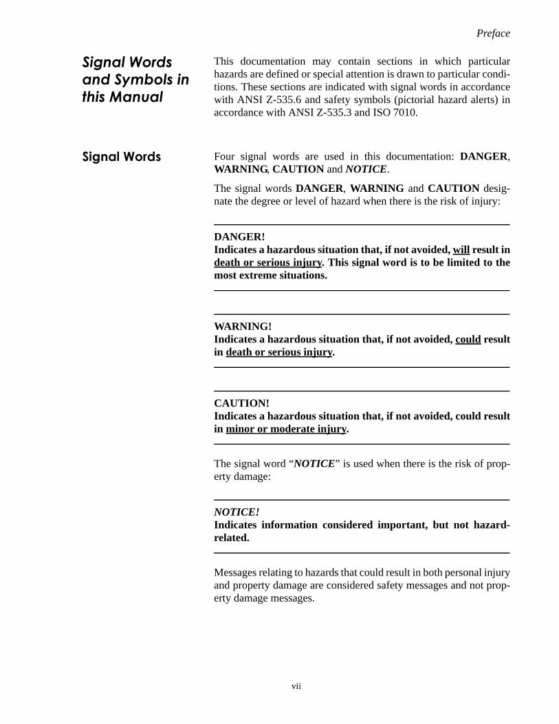
This documentation may contain sections in which particularhazards are defined or special attention is drawn to particular condi-tions. These sections are indicated with signal words in accordancewith ANSI Z-535.6 and safety symbols (pictorial hazard alerts) inaccordance with ANSI Z-535.3 and ISO 7010.
Signal Words Four signal words are used in this documentation: DANGER,WARNING, CAUTION and NOTICE.
The signal words DANGER, WARNING and CAUTION desig-nate the degree or level of hazard when there is the risk of injury:
DANGER!Indicates a hazardous situation that, if not avoided, will result indeath or serious injury. This signal word is to be limited to themost extreme situations.
WARNING!Indicates a hazardous situation that, if not avoided, could resultin death or serious injury.
CAUTION!Indicates a hazardous situation that, if not avoided, could resultin minor or moderate injury.
The signal word “NOTICE” is used when there is the risk of prop-erty damage:
NOTICE!Indicates information considered important, but not hazard-related.
Messages relating to hazards that could result in both personal injuryand property damage are considered safety messages and not prop-erty damage messages.
vii
EnergyMax-USB/RS User Manual
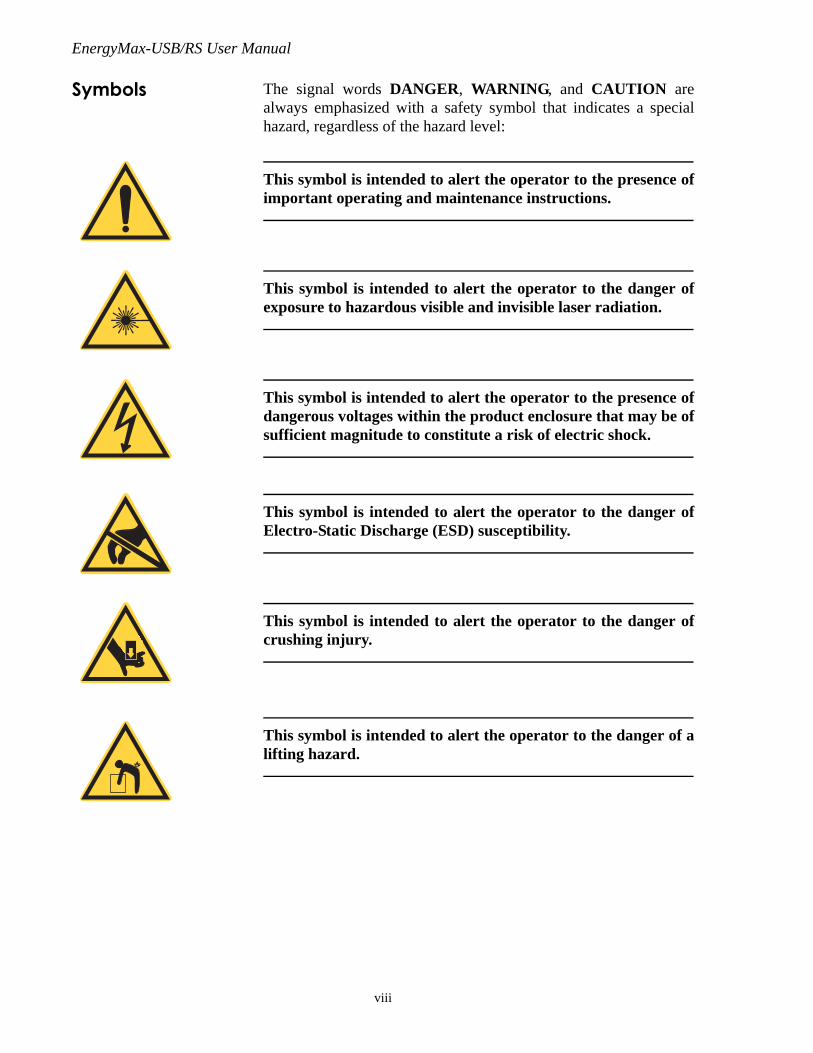
Symbols The signal words DANGER, WARNING, and CAUTION arealways emphasized with a safety symbol that indicates a specialhazard, regardless of the hazard level:
This symbol is intended to alert the operator to the presence ofimportant operating and maintenance instructions.
This symbol is intended to alert the operator to the danger ofexposure to hazardous visible and invisible laser radiation.
This symbol is intended to alert the operator to the presence ofdangerous voltages within the product enclosure that may be ofsufficient magnitude to constitute a risk of electric shock.
This symbol is intended to alert the operator to the danger ofElectro-Static Discharge (ESD) susceptibility.
This symbol is intended to alert the operator to the danger ofcrushing injury.
This symbol is intended to alert the operator to the danger of alifting hazard.
viii
Preface
Preface This manual presents user information for the CoherentEnergyMax™ meterless energy sensors.
For complete software installation instructions, refer to theEnergyMax-USB/RS Software Installation and Quick Start Guide(1186241)—inside the CD case that shipped with your product.
Export Control Laws Compliance
It is the policy of Coherent to comply strictly with U.S. exportcontrol laws.
Export and re-export of lasers manufactured by Coherent are subjectto U.S. Export Administration Regulations, which are administeredby the Commerce Department. In addition, shipments of certaincomponents are regulated by the State Department under the Inter-national Traffic in Arms Regulations.
The applicable restrictions vary depending on the specific productinvolved and its destination. In some cases, U.S. law requires thatU.S. Government approval be obtained prior to resale, export orre-export of certain articles. When there is uncertainty about theobligations imposed by U.S. law, clarification must be obtainedfrom Coherent or an appropriate U.S. Government agency.
Products manufactured in the European Union, Singapore,Malaysia, Thailand: These commodities, technology, or software aresubject to local export regulations and local laws. Diversion contraryto local law is prohibited. The use, sale, re-export, or re-transferdirectly or indirectly in any prohibited activities are strictly prohib-ited.
Publication Updates
To view information that may have been added or changed since thispublication went to print, connect to: www.Coherent.com.
Unpacking and Inspection
All components of the Coherent EnergyMax-USB/RS sensor systemare carefully tested and inspected before shipment.
NOTICE!Save the inner container to store the components when not in useand to send the components to Coherent for calibration.
ix

EnergyMax-USB/RS User Manual
Inspect each of the following items for damage:
• The EnergyMax sensor
• Post and stand components—refer to “Post and StandAssembly,” below.
• Damage test slide (only included with sensors that do not havea built-in diffuser window)
• Heatsink, if ordered (optional accessory)
Advise Coherent immediately of any shortages or damage—refer to“Obtaining Service” (p. 7-5). A Returned Material Authorization(RMA) will be issued for any damaged sensor—refer to “ProductShipping Instructions” (p. 7-6).
Post and Stand Assembly
Post
Stand
1/4-20 SHC Screw(supplied)
Hex Key (supplied)
Post HolderThumbscrew
x

Safety
SAFETY
Carefully review the following safety information to preventpersonal injury and to prevent damage to this product or any equip-ment connected to it. There are no user-serviceable parts in CoherentEnergyMax sensors. For service information, refer to “ObtainingService” (p. 7-5).
WARNING!Do not operate the system if its panels are removed or any of theinternal circuitry is exposed.
WARNING!Do not operate the system in wet or damp conditions, or in anexplosive environment.
NOTICE!Do not operate the system if there are suspected failures. Referdamaged units to qualified Coherent service personnel.
Environmental Regulations
RoHS Compliance These Coherent products are RoHS (EU Restriction of HazardousSubstances) compliant.
Waste Electrical and Electronic Equipment (WEEE, 2002)
The European Waste Electrical and Electronic Equipment (WEEE)Directive (2002/96/EC) is represented by a crossed-out garbagecontainer label (Figure 1-1, below). The purpose of this directive isto minimize the disposal of WEEE as unsorted municipal waste andto facilitate its separate collection.
Figure 1-1. Waste Electrical and Electronic Equipment Label
1 - 1

EnergyMax-USB/RS User Manual
Declaration of Conformity
Declaration of Conformity certificates are available upon request.
1 - 2
Description
DESCRIPTION
In this section:
• Introduction (this page)
• Product overview (p. 2-2)
• Sensor overview (p. 2-3)
• MaxBlack EnergyMax sensors (p. 2-4)
• Diffuse Metallic EnergyMax sensors (p. 2-5)
• MaxBlack EnergyMax sensors with diffusers (p. 2-6)
• MaxUV EnergyMax sensors (p. 2-7)
• Quantum EnergyMax sensor (p. 2-8)
Introduction EnergyMax-USB/RS sensors have miniaturized meter electronicsthat are integrated within the sensor cable. The entire range ofCoherent high performance EnergyMax sensors is available in thisform factor with either RS-232 or USB 2.0 connectivity, enablingthe measurement of the energy per pulse or average power of pulsedlasers from the nanojoule to the multi-joule level, over wavelengthsfrom the deep ultraviolet through the far infrared, and from singlepulses to repetition rates of 10 kHz (with measurement of everypulse). Multiple EnergyMax sensors can share a trigger (internal orexternal) for synchronized operation, for example to enable pulseratiometry.
Furthermore, EnergyMax USB/RS sensors significantly decreasethe overall cost of ownership by removing the need to purchase aseparate, more costly meter with each sensor, and by decreasingannual calibration costs related to integrating the electronics into thesensor. These products are also useful in the lab and research settingbecause they can be used as standalone instruments with a computer,or integrated smoothly into any experiment with an automatedcontrol and data acquisition system.
These meterless sensors are particularly attractive to system buildersbecause their small size permits them to be easily embedded withininstrumentation, and their RS-232 or USB communications capabil-ities facilitate automated operation by a host computer.
2 - 1
EnergyMax-USB/RS User Manual
Coherent EnergyMax PC application software provides a virtualinstrument interface for sensors that enable the operator to take laserenergy readings, log data, and compute measurement statistics.Users can also write their own software using host interfacecommands that control all aspects of energy meter operation.
Product Overview
Product Features • Able to measure every pulse up to 10 kHz and stream this dataover the host port (USB only). RS-232 capable of measuringevery pulse up to 10 KHz and streaming data over host port ata rate of 1 kHz.
• EnergyMax-USB provides direct USB high-speed 2.0 connec-tion to PC. Power provided via USB connection.
• EnergyMax-RS provides RS-232 connectivity. Power inputprovided via +4-to-20 VDC input.
• Fast 14-bit A/D converter supports measurement accuracysimilar to that found in LabMax-TOP meter.
• Up to five digits of measurement resolution.
• Each sensor incorporates a unique spectral compensationcurve for accurate use at wavelengths that differ from the cali-bration wavelength.
• External and internal triggering available.
• Units can share triggers to provide synchronized measure-ments for applications, such as ratiometry.
2 - 2

Description
Software Features
EnergyMax PC applications software is supplied free with everyEnergyMax sensor and includes the following features:
• Trending, tuning, histogram at data rate up to 1 kHz.
• Statistics (mean, minimum, maximum, and standard deviation,dose, fluence, and missed pulses).
• Ability to log data to a file at up to 10 kHz (in Turbo mode).
• Operate multiple devices simultaneously and performsynchronized ratiometry (A/B analysis). Trend and log resultsto file.
For system integration and for implementations involving customerwritten software, EnergyMax sensors provide an in-depth commandset that is easy to access:
• USB sensors connect on Virtual COM port, thus supportingsimple ASCII host commands communication for remoteinterfacing.
• National Instruments™ LabVIEW™ drivers are supplied foreasy LabVIEW integration.
Sensor Overview
Coherent EnergyMax sensors are known as “smart” sensors—thatis, they incorporate onboard electronics that automatically correctfor pyroelectric sensor temperature, as well as built-in wavelengthcompensation factors.
This section gives an overview of each of the five types of sensorsthat comprise the EnergyMax Family: MaxBlack, Diffuse Metallic,MaxBlack With Diffusers, MaxUV, and Quantum.
2 - 3

EnergyMax-USB/RS User Manual
MaxBlack EnergyMax Sensors
The MaxBlack EnergyMax series has six different models thatpermit measurement over a wide range of wavelengths, beam diam-eters, average power levels, and repetition rates. All MaxBlackEnergyMax sensors feature the MaxBlack coating, which offerssignificantly better damage resistance and mechanical durabilitycharacteristics compared to black paint coatings.
The 25 and 50 mm diameter sensors accept a user-installable,optional heatsink—refer to “Increasing Average Power With Heat-sinks” (p. 3-1)—which can extend the energy and/or repetition raterange. These heatsinks allow 25 mm sensors to be used up to 15Waverage power, and 50 mm sensors to be used up to 24W averagepower.
NOTICE!Use of EnergyMax sensors at average power levels beyond thebase model average power specification—without the optionalheatsink—can cause permanent damage to the sensor.
Table 2-1. MaxBlack EnergyMax Sensor Specifications
J-50MB-HE J-50MB-LE J-25MB-HE J-25MB-LE J-10MB-HE J-10MB-LE
Energy Range 1.6 mJ to 2J 400 µJ to 500 mJ 850 µJ to 1J 50 µJ to 50 mJ 12 µJ to 20 mJ 500 nJ to 600 µJ
Noise Equivalent Energy < 160 µJ < 40 µJ < 85 µJ < 5 µJ < 1.2 µJ < 50 nJ
Wavelength Range (µm) 0.19 to 12
Active Area Diameter(mm)
50 50 25 25 10 10
Max. Avg. Power (W) 10 10 5 5 4 4
Max. Pulse Width (µs) 57 17
Max. Rep. Rate (pps) 300 1000
Max. Energy Density(mJ/cm2)
500 (at 1064 nm, 10 ns)
Sensor Coating MaxBlack
Diffuser No
Calibration Wavelength(nm)
1064
Calibration Uncertainty(%)
± 2
Energy Linearity (%) ± 3
Cable Length (m)3 (sensor cable)
1 (USB/RS cable)
Cable Type USB and RS
Item Number
USBRS
11914441191432
1191443-
1191442-
11914411191431
11914361191429
11914351191428
2 - 4

Description
Diffuse Metallic EnergyMax Sensors
Diffuse Metallic EnergyMax sensors feature broad wavelengthcoverage (190 nm to 2.1 µm) and large active area (up to 50 mm).
This series of EnergyMax sensors has three different models thatallow measurement over a wide range of wavelengths, beam diame-ters, average power levels, and repetition rates. These sensorsfeature a unique diffused metallic coating which offers significantlyhigher damage resistance than traditional metallic coatings andcauses very little specular reflectance, thus eliminating spuriousbeams that can re-enter the laser cavity.
The 25 mm and 50 mm sensors accept a user-installable, optionalheatsink—refer to “Increasing Average Power With Heatsinks”(p. 3-1)—which can extend the energy and/or repetition rate range.These heatsinks allow the J-25MT-10KHZ to be used up to 30Waverage power, and J-50MT-10KHZ to be used up to 50W averagepower.
NOTICE!Use of EnergyMax sensors at average power levels beyond thebase model average power specification—without the optionalheatsink—can cause permanent damage to the sensor.
Table 2-2. Diffuse Metallic EnergyMax Sensor Specifications
J-50MT-10KHZ J-25MT-10KHZ J-10MT-10KHZ
Energy Range 400 µJ to 1J 90 µJ to 100 mJ 300 nJ to 200 µJ
Noise Equivalent Energy < 40 µJ < 9 µJ < 30 nJ
Wavelength Range (µm) 0.19 to 2.1
Active Area Diameter (mm) 50 25 10
Max. Avg. Power (W) 20 10 1
Max. Pulse Width (µs) 1.7
Max. Rep. Rate (pps) 10,000
Max. Energy Density (mJ/cm2) 500 (at 1064 nm, 10 ns) 50 (@ 1064 nm, 10 ns)
Sensor Coating Diffuse Metallic
Diffuser No
Calibration Wavelength (nm) 1064
Calibration Uncertainty (%) ± 2
Energy Linearity (%) ± 3
Cable Length (m)3 (sensor cable)
1 (USB/RS cable)
Cable Type USB and RS
Item Number
USBRS
11914171191433
1191446-
1191445-
2 - 5

EnergyMax-USB/RS User Manual
MaxBlack EnergyMax Sensors With Diffusers
These sensors are specifically designed for high energy and highpeak power lasers operating at relatively low repetition rates, suchas those based on Nd:YAG, Ruby, Ho:YAG, and Erbium. TheJ-50MB-YAG sensor can be used with beams up to 35 mm in diam-eter and can work at 1064 nm, 532 nm, 355 nm, and 266 nm withoutthe need to change or self-calibrate diffusers or any other accesso-ries. Both sensors combine a MaxBlack coating and a diffuser toproduce superior damage resistance characteristics. This combina-tion enables operation with lasers that produce either very highenergy per pulse or very high peak fluences.
NOTICE!Use of EnergyMax sensors at average power levels beyond thebase model average power specification—without the optionalheatsink—can cause permanent damage to the sensor.
Table 2-3. MaxBlack EnergyMax Sensor With Diffusers Specifications
J-50MB-YAG J-50MB-IR
Energy Range 2.4 mJ to 3Ja
a. Modified sensors with higher repetition rate, energy range, and/or pulse width are available. Con-tact Coherent.
3.2 mJ to 3J
Noise Equivalent Energy (µJ) < 240 < 320
Wavelength Range (µm) 0.266 to 2.1 0.5 to 3.0
Max. Beam Size (mm) 35 30
Max. Avg. Power (W) 20 15
Max. Pulse Width (µs) 340 1000
Max. Rep. Rate (pps) 50 30Max. Energy Density (J/cm2) 14.0 (at 1064 nm, 10 ns)
2.8 (at 532 nm, 10 ns)0.75 (at 355 nm, 10 ns)1.0 (at 266 nm, 10 ns)
> 100 (at 2940 nm, 100 µs)
Sensor Coating MaxBlack
Diffuser YAG IR
Calibration Wavelength (nm) 1064 1064, 2940
Calibration Uncertainty (%) ± 2
Energy Linearity (%) ± 3 ± 3.5
Cable Length (m)3 (sensor cable)
1 (USB/RS cable)
Cable Type USB and RS
Item Number
USBRS
11914371191430
1191440-
2 - 6

Description
MaxUV EnergyMax Sensors
These sensors are specifically optimized for use with ArF lasersoperating at 193 nm and KrF lasers operating at 248 nm, and featurehigh accuracy and large active areas (up to 50 mm). The EnergyMaxseries uses a unique coating—called MaxUV—that delivers supe-rior long-term damage resistance.
Two of the 50 mm diameter models (labeled as “with Diffuser” inthe model name) incorporate a DUV quartz diffuser for increasedcoating damage resistance.
Both sensors accept an user-installable, optional heatsink—refer to“Increasing Average Power With Heatsinks” (p. 3-1)—which canincrease the maximum energy or average power range. These heat-sinks allow 25 mm sensors to be used up to 18W average power, and50 mm sensors to be used up to 43W average power (both at193 nm).
NOTICE!Use of EnergyMax sensors at average power levels beyond thebase model average power specification—without the optionalheatsink—can cause permanent damage to the sensor.
Table 2-4. MaxUV EnergyMax Sensor Specifications
J-50MUV-248(W/DIFFUSER)
J-25MUV-193(W/O DIFFUSER)
Energy Range 800 µJ to 1J 90 µJ to 100 mJ
Noise Equivalent Energy (µJ) < 80 < 9
Wavelength Range (µm) 0.19 to 0.266 0.19 to 2.1
Active Area Diameter (mm) 50 25
Max. Average Power (W) 15 5
Max. Pulse Width (µs) 86 43
Max. Rep. Rate (pps) 200 400
Max. Energy Density (mJ/cm2) 520 (@ 248 nm, 10 ns) 200 (@ 193 nm, 10 ns)
Sensor Coating MaxUV
Diffuser DUV No
Calibration Wavelength (nm) 248 193
Calibration Uncertainty (%) ± 3
Energy Linearity (%) ± 3
Cable Length (m)3 (sensor cable)
1 (USB/RS cable)
Cable Type USB
Item NumberUSB 1191449 1191448
2 - 7
EnergyMax-USB/RS User Manual
Quantum EnergyMax Sensor
The Quantum EnergyMax sensor incorporates a Silicon photodiode,has a large 10 mm clear aperture, and operates at a repetition ratefrom single pulse up to 10 kHz (every pulse).
The main difference between a Quantum EnergyMax sensor andother Coherent EnergyMax sensors is its sensitivity. A QuantumEnergyMax sensor can measure much smaller signals than the restof the EnergyMax sensor line because it uses a photodiode—ratherthan a pyroelectric—element.
Due to the quantum nature of their response, photodiode sensors areinherently more sensitive than pyroelectric sensors, which arethermal-based. One consequence of this extra sensitivity is thepossibility of measurement error or noise from stray modulated lightsources (for example, stray reflections or room lights) in a laboratoryenvironment. For this reason Quantum EnergyMax sensors aredesigned for use with a small integrated input beam tube, whichlimits the field of view of the sensor aperture. This tube is removablefor alignment purposes and custom applications.
The following chart plots the minimum and maximum measurableenergy across all wavelengths. This chart can be used to find themeasurable energy range for wavelengths different from that in thespecifications table (532 nm).
The output of the Silicon and Germanium photodiodes used in theQuantum EnergyMax sensors varies greatly by wavelength. Thesensors have spectral compensation to account for this varia-
Figure 2-1. Spectral Sensitivity Curves for Quantum EnergyMax Sensor
J-10Si-HE
Wavelength (nm) 200 800 600 400
10 pJ
1 pJ
100 pJ
1 nJ
10 nJ
100 nJ
1 μJ
10 μJ
1000 1800 1600 1400 1200
Ener
gy (J
)
2 - 8

Description
tion—refer to “Spectral Response” (p. 3-5)—so that measurementsare still accurate when used at wavelengths different from the cali-bration wavelength.
Table 2-5. Quantum EnergyMax Sensor Specifications
J-10SI-HE
Energy Range 750 pJ to 775 nJ (at 532 nm)
Noise Equivalent Energy < 75 pJ (at 532 nm)
Wavelength Range (nm) 325 to 900
Active Area Diameter (mm) 10
Max. Avg. Power (mW) 60
Max. Pulse Width (µs) 1
Max. Rep. Rate (pps) 10000
Sensor Silicon
Diffuser ND2
Calibration Wavelength (nm) 532
Calibration Uncertainty (%) ± 3
Linearity (%) ± 3
Cable Length (m)3 (sensor cable)
1 (USB/RS cable)
Cable Type USB and RS
Item Number
USBRS
11914341191427
2 - 9

EnergyMax-USB/RS User Manual
2 - 10

Technical Description
TECHNICAL DESCRIPTION
In this section:
• Increasing average power with heatsinks (this page)
• Pyroelectric technology (p. 3-2)
• Damage thresholds (p. 3-3)
• Measurement linearity (p. 3-4)
• Spectral response (p. 3-5)
Increasing Average Power With Heatsinks
Using a heatsink increases the average power handling capability ofEnergyMax sensors. These power levels are done by combiningactive temperature compensation circuitry and enhanced thermalmanagement techniques. Maximum average power is wavelengthdependent because absorption changes with wavelength. Maximumaverage power is inversely proportional to the spectral absorption.
The 25 mm and 50 mm aperture sensors accept optional heatsinksthat users can install by mounting them on the back of the sensor.The heatsinks expand the average power handling capability asoutlined below. Average power specification is dependent oncoating and wavelength. Table 3-1 (p. 3-2) shows average powerratings for several wavelength and sensor combinations. Note that10 mm aperture sensors do not accept heatsinks, 25 mm aperturesensors accept small and medium heatsinks, and 50 mm aperturesensors accept large heatsinks.
NOTICE!Use of EnergyMax sensors at average power levels beyond thebase model average power specification—without the optionalheatsink—can cause permanent damage to the sensor.
3 - 1

EnergyMax-USB/RS User Manual
Table 3-2, below, lists the different heatsinks that are available forEnergyMax sensors.
Pyroelectric Technology
Different from all other thermal sensors, pyroelectrics measure therate of change of the sensor temperature, rather than the temperaturevalue itself. As a result, the response speed of the pyroelectric isusually limited by its electrical circuit design and the thermal resis-tance of the absorptive coating. In contrast, other thermal sensors(for example thermopiles and bolometers) are limited by slowerthermal response speeds, typically on the order of seconds. Pyro-electrics respond only to changing radiation that is chopped, pulsed,or otherwise modulated, so they ignore steady background radiationthat is not changing with time. Their combination of wide uniformspectral response, sensitivity, and high speed make pyroelectricsideal choices for a vast number of electro-optic applications.
Table 3-1. Average Power Ratingsa
a. Average power ratings are based upon testing at the listed wavelength (not applicable for Quantum EnergyMax sensors).
Heatsink
Model Wavelength (nm) None Small Medium Large
J-50MB-HEb & LE2
b. 50 mm EnergyMax sensors are compatible with the large heatsink.
1064 10W - - 24W
J-25MB-HEc & LE3
c. 25 mm EnergyMax sensors are compatible with small and medium heatsinks.
1064 5W 10W 15W -
J-10MB-HEd & LE4
d. 10 mm EnergyMax sensors do not have a heatsink available.
1064 4W - - -
J-50MT-10KHZ2 1064 20W - - 49W
J-25MT-10KHZ3 1064 10W 20W 31W -
J-10MT-10KHZ4 1064 1W - - -
J-50MB-YAG2 1064 20W - - 48W
J-50MB-IR 1064, 2940 15W - - -
J-50MUV-2482 w/o Diffuser 248 10W - - 25W
J-25MUV-1933 193 5W 10W 15W -
Table 3-2. Available Heatsinks
ItemNumber
Name Description
1123430 Small heatsink Increases average power handling on 25 mm aperture EnergyMax sensors
1123431 Medium heatsink
1123432 Large heatsink Increases average power handling on 50 mm aperture EnergyMax sensors
3 - 2
Technical Description
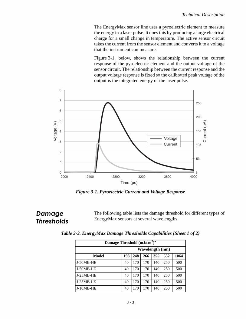
The EnergyMax sensor line uses a pyroelectric element to measurethe energy in a laser pulse. It does this by producing a large electricalcharge for a small change in temperature. The active sensor circuittakes the current from the sensor element and converts it to a voltagethat the instrument can measure.
Figure 3-1, below, shows the relationship between the currentresponse of the pyroelectric element and the output voltage of thesensor circuit. The relationship between the current response and theoutput voltage response is fixed so the calibrated peak voltage of theoutput is the integrated energy of the laser pulse.
Damage Thresholds
The following table lists the damage threshold for different types ofEnergyMax sensors at several wavelengths.
Figure 3-1. Pyroelectric Current and Voltage Response
Table 3-3. EnergyMax Damage Thresholds Capabilities (Sheet 1 of 2)
Damage Threshold (mJ/cm2)a
Wavelength (nm)
Model 193 248 266 355 532 1064
J-50MB-HE 40 170 170 140 250 500
J-50MB-LE 40 170 170 140 250 500
J-25MB-HE 40 170 170 140 250 500
J-25MB-LE 40 170 170 140 250 500
J-10MB-HE 40 170 170 140 250 500
3 - 3

EnergyMax-USB/RS User Manual
Measurement Linearity
Coherent has designed the EnergyMax sensor line to greatlydecrease several linearity effects common in pyroelectric energysensors. The outcome of this design effort is increased performancethat is now better than at any time in the history of pyroelectricpulsed laser energy measurement.
Energy Linearity Energy linearity across the entire specified energy range of an Ener-gyMax sensor is +/- 3%. Within 10 to 90% of the energy range spec-ification the sensors are typically linear to +/- 2%. (The J-50MB-IRhas a slightly higher energy linearity specification of +/- 3.5%.)
Repetition Rate Linearity
Repetition rate linearity is +/- 1%. In practice, the actual error isoften much less than 1%.
Average Power Linearity
The pyroelectric crystal is sensitive to temperature at a rate ofapproximately 0.2% per degree Celsius change in temperature.Historically this has limited the average power to which a sensor canbe exposed. This circuit permits measurement of higher pulseenergy at faster repetition rates than ever before and enables the useof removable heatsinks.
EnergyMax sensors have less than 2% error when used at maximumaverage power, and have less than 0.5% undershoot when hit withthe full power rating. In practice, many EnergyMax sensors havetypical average power linearity error of less than 1%.
J-10MB-LE 40 170 170 140 250 500
J-50MT-10KHZ 150 200 200 390 500 500
J-25MT-10KHZ 150 200 200 390 500 500
J-10MT-10KHZ 40 40 40 50 50 50
J-50MB-YAG - - 1000 750 2800 14000
J-50MUV-248 (w/diffuser) 400 520 520 - - -
J-25MUV-193 200 260 260 300 375 375
a. Not applicable for Quantum EnergyMax sensors.
Table 3-3. EnergyMax Damage Thresholds Capabilities (Sheet 2 of 2)
Damage Threshold (mJ/cm2)a
Wavelength (nm)
3 - 4

Technical Description
Temperature Linearity of Quantum EnergyMax Sensors
The Silicon Quantum EnergyMax sensor (J-10SI-HE) has atemperature linearity component because of a photo sensitivitytemperature characteristic that varies by wavelength, as shown in thefigure below. In practice, the error is less than 1%, unless the sensorsare used in a very hot environment. To calculate Δ°C, compare thetemperature of the environment within which the sensor is beingused, to the calibration temperature. Add 1 to 2°C for sensor elec-tronics.
Pulse Width Linearity
There is a small amount of pulse width linearity error when using asensor at its maximum specified pulse width. This error is less than1%. At pulse widths less than 10 µs this error is negligible and is lessthan 0.5%. (The J-50MB-IR sensor has a slightly higher pulse widthlinearity specification of +/- 1.5%.)
Spectral Response
All pyroelectric EnergyMax sensors incorporate a diffuse coating tominimize specular reflections, which eliminates spurious beams thatcan re-enter the laser cavity.
In addition, all EnergyMax sensors include the convenience ofonboard electronics that have built-in wavelength compensationfactors. Enter the wavelength of the laser being measured within thePowerMax PC software (or by a host command) and the sensor
Figure 3-2. Photo Sensitivity Temperature Characteristics
Tem
pera
ture
Coe
ffici
ent (
%/°
C)
+ 1.5
+ 1.0
+ 0.5
0
- 0.5 190 400 600 800 1000
(Typ.)
Wavelength (nm)
3 - 5

EnergyMax-USB/RS User Manual
output will be automatically compensated. Wavelength compensa-tion results in an additional error factor when engaged and when thesensor is being used at a wavelength different from the wavelengthat which it was calibrated. The accuracy is based upon the sensorcoating.
Applying Wavelength Compensation Accuracy
Overall measurement accuracy is a combination of calibrationuncertainty (found in the sensor specification tables) and the wave-length compensation accuracy—refer to Table 3-4, below.
The combined accuracy is based upon practices outlined in theNational Institute of Standards Guidelines for Evaluating andExpressing Uncertainty (NIST Technical Note 1297, 1994 Edition).The combined accuracy of the measurement is calculated by usingthe law of propagation of uncertainty using the “root-sum-square”(square root of the sum of squares), sometimes described assumming in quadrature, where:
Measurement Accuracy =
where U = 'Percent Calibration Uncertainty' and W = 'Wave-length Accuracy'
Example 1
J-10SI-HE used at 355 nm
U = 3%W = 5%
Measurement Accuracy = = = 5.8%
Example 2
J-10MB-LE used at 532 nm
U = 2%W = 2%
Measurement Accuracy = = = 2.8%
22 WU
22 53 259
22 22 44
Table 3-4. Wavelength Compensation Accuracy (Sheet 1 of 2)
SensorWavelength Compensation Accuracy (%)
(for wavelengths other than the calibration wavelength)
CalibrationWavelength
(nm)
All Multipurpose sensors (MaxBlack coating) ± 2% 1064 nm
All High Rep. Rate sensors (Diffuse metalliccoating)
± 3%
J-50MB-YAG ± 2%
J-50MB-IR ± 3% 1064, 2940 nm
3 - 6
Technical Description
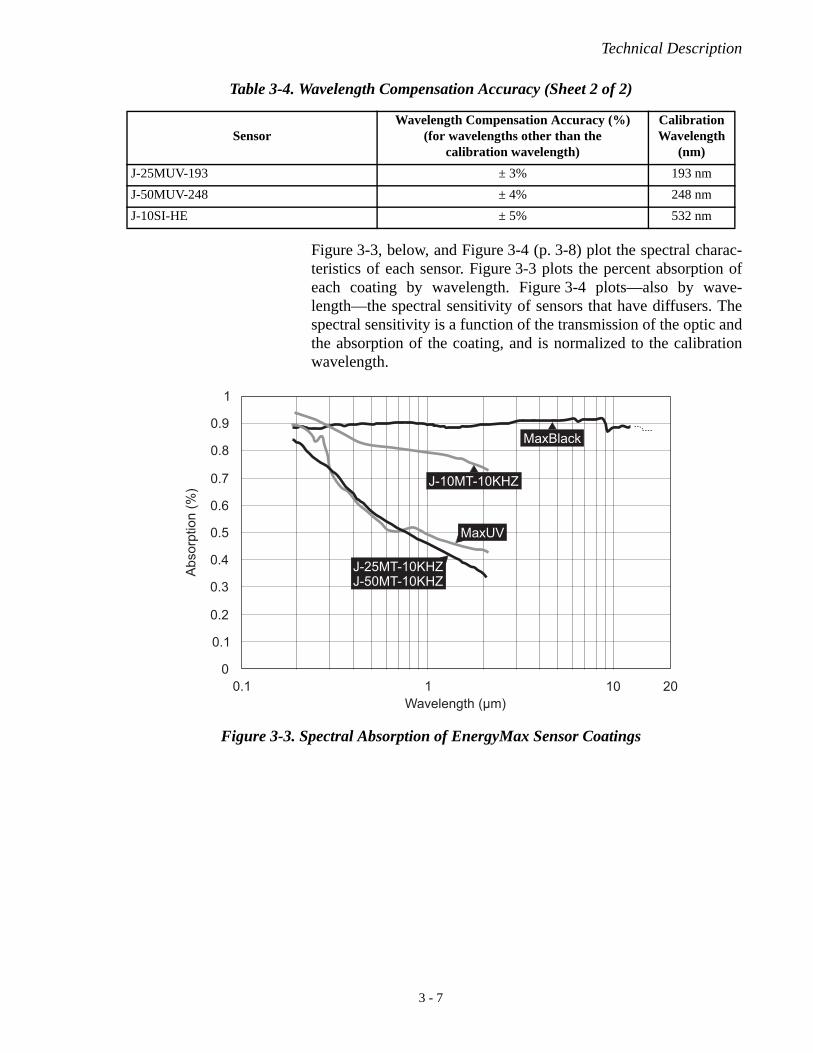
Figure 3-3, below, and Figure 3-4 (p. 3-8) plot the spectral charac-teristics of each sensor. Figure 3-3 plots the percent absorption ofeach coating by wavelength. Figure 3-4 plots—also by wave-length—the spectral sensitivity of sensors that have diffusers. Thespectral sensitivity is a function of the transmission of the optic andthe absorption of the coating, and is normalized to the calibrationwavelength.
J-25MUV-193 ± 3% 193 nm
J-50MUV-248 ± 4% 248 nm
J-10SI-HE ± 5% 532 nm
Table 3-4. Wavelength Compensation Accuracy (Sheet 2 of 2)
SensorWavelength Compensation Accuracy (%)
(for wavelengths other than the calibration wavelength)
CalibrationWavelength
(nm)
Figure 3-3. Spectral Absorption of EnergyMax Sensor Coatings
Wavelength (μm)0.1 20101
0.1
0
0.2
0.3
0.4
0.5
0.6
0.7
0.8
0.9
1
MaxBlack
J-10MT-10KHZ
MaxUV
Abs
orpt
ion
(%)
J-25MT-10KHZJ-50MT-10KHZ
3 - 7

EnergyMax-USB/RS User Manual
Figure 3-4. Spectral Sensitivity of EnergyMax Sensors With Diffusers
J-50MUV-248J-50MB-YAG
J-50MB-IR
3 - 8
Operation
OPERATION
In this section:
• LED status indicator (this page)
• Powering EnergyMax-RS sensors (p. 4-2)
• Pyroelectric Watts mode (p. 4-2)
• Triggering (p. 4-3)
• Internal Triggering mode (p. 4-3)
• Setting the wavelength (p. 4-4)
• Tutorial: Measuring energy With a EnergyMax sensor (p. 4-5)
• Tutorial: Synchronization (p. 4-7)
• Tutorial: Turbo mode (p. 4-12)
• Using the software (p. 4-14)
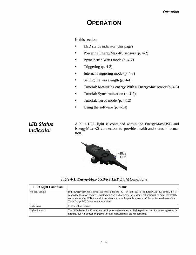
LED Status Indicator
A blue LED light is contained within the EnergyMax-USB andEnergyMax-RS connectors to provide health-and-status informa-tion.
Table 4-1. EnergyMax-USB/RS LED Light Conditions
LED Light Condition Status
No light visible If the EnergyMax-USB sensor is connected to the PC—or, in the case of an EnergyMax-RS sensor, if it is connected to a power source—but there are no visible lights, the sensor is not powering up properly. Test the sensor on another USB port and if that does not solve the problem, contact Coherent for service—refer to Table 7-1 (p. 7-5) for contact information.
Light is on Sensor is functioning.
Lights flashing The LED flashes for 50 msec with each pulse measurement. At high repetition rates it may not appear to be flashing, but will appear brighter than when measurements are not occurring.
BlueLED
4 - 1

EnergyMax-USB/RS User Manual
Powering EnergyMax-RS Sensors
The EnergyMax-RS sensor is powered via a + 4 to 20 VDC powersupply input. This power can be applied with either an externalpower supply (not included), as shown below, or input through Pin 1of the DB-9 connector. An optional external power supply can beordered using part number 1105557.
Pyroelectric Watts Mode
EnergyMax pyroelectric sensors can measure average power from aseries of pulses. Selecting the power measurement mode will changethe EnergyMax software to display and trend data based on averagepower readings.
Average power is calculated by measuring the energy of the pulsesand dividing by the periods between them and, thus, requires at leasttwo pulses to make a power measurement. Each subsequent pulsedefines the period for the previous pulse until the last pulse (seefigure, below). The last pulse in a pulse burst will not yield a powermeasurement since the period after the last pulse is indeterminate.This method permits more accurate tracking of initial average powertransients for pulsed lasers.
When measuring the average power of a laser burst or continuouspulse train, the frequency of the pulses must be greater than or equalto 1 Hz, and less than or equal to the maximum repetition rate capa-
+4 to 20 VDC power supply
Meterless sensorpower cable connector
USB or RS-232 cable connector
Sensor cable
EnergyMax-RS System Components
Power supply cable connector
Figure 4-1. Average Power Diagram
indeterminate
E 0 E 1 E 2 E 3 E n
t 0 t 1 t 2 t 3 t n
4 - 2

Operation
bility of the pyroelectric sensor. Multiple bursts separated by onesecond or less are treated as a single burst and, accordingly, the gapbetween bursts appears as a lower power.
Short bursts with rep rates greater than 1 kHz may not yield apower measurement.
Triggering EnergyMax sensors can be triggered externally via the Ext Trigconnector. This is particularly useful in an electrically-noisy envi-ronment. EnergyMax sensors can be set to synchronize with eitherthe positive or negative transition of this external signal.
When a reliable external trigger is not available, an EnergyMaxsensor can be set to use its own internal circuitry to extract a triggerfrom the incoming signal. This is called Internal Triggering(discussed, below).
Internal Triggering Mode
Internal triggering refers to finding a trigger automatically from theincoming signal.
The trigger level setting helps filter out low-level noise that cancause false triggering from the sensor. The trigger level is apercentage of the energy level listed for the measurement range thatis currently selected. So if a measurement range of 50 mJ is selectedin the software and a trigger level of 1% is entered, the triggerthreshold will be 0.5 mJ. This means that any values above 0.5 mJwill be captured as a valid reading, and any values below 0.5 mJ willbe ignored as noise. Using the combination of the measurementrange selection and the trigger level setting can help the sensor accu-rately measure without picking up noise or false triggers in the read-ings.
4 - 3

EnergyMax-USB/RS User Manual
In the following figure, the internal trigger threshold has been set to8% (shown as a dashed line). Pulse A will definitely not generate areliable trigger. Pulse B may generate a trigger, but not reliably.Pulses C and D will definitely generate reliable triggers.
The trigger is synchronous with the leading edge of the pulse, but theactual peak is determined algorithmically by sampling the inputsignal near the trigger. From the trigger point forward, the algorithmsearches for peaks and from the trigger point back, it searches for abaseline.
Setting the Wavelength
The wavelength should always be set for accurate power measure-ments. This can be done either in the EnergyMax PC applicationsoftware or over the host port via a host command.
Figure 4-2. Internal Trigger Threshold
8% Trigger Level
15%
10%
5%
Definitely will trigger May trigger, but not reliable Definitely will not trigger
A B C D
4 - 4

Operation
Tutorial: Measuring Energy With a EnergyMax Sensor
This tutorial describes how to connect a EnergyMax-USB or Ener-gyMax-RS sensor to your PC and start taking energy measurementsusing the EnergyMax PC software.
WARNING!Follow all laser safety procedures. The laser must be switchedOFF or shuttered before running the tutorial given in thissection.
NOTICE!For instructions on communicating with the sensor directly viahost commands, refer to “Host Interface” (p. 6-1).
1. Install the EnergyMax PC software—for details, refer to theEnergyMax-USB/RS Software Installation and Quick StartGuide (1186241) that shipped with your system.
2. Connect the system components (the following figure showssystem components for both EnergyMax-USB and Ener-gyMax-RS sensors—select the one that’s applicable for yoursystem).
+4 to 20 VDC power supply
Meterless sensor power cable connector
RS-232 cable connector
Sensor cable
EnergyMax-RS System Components
Power supply cable connector
USB cable connector
Sensor cable
EnergyMax-USB System Components
4 - 5

EnergyMax-USB/RS User Manual
3. Confirm that the blue LED is lit.
4. Start the EnergyMax PC software.
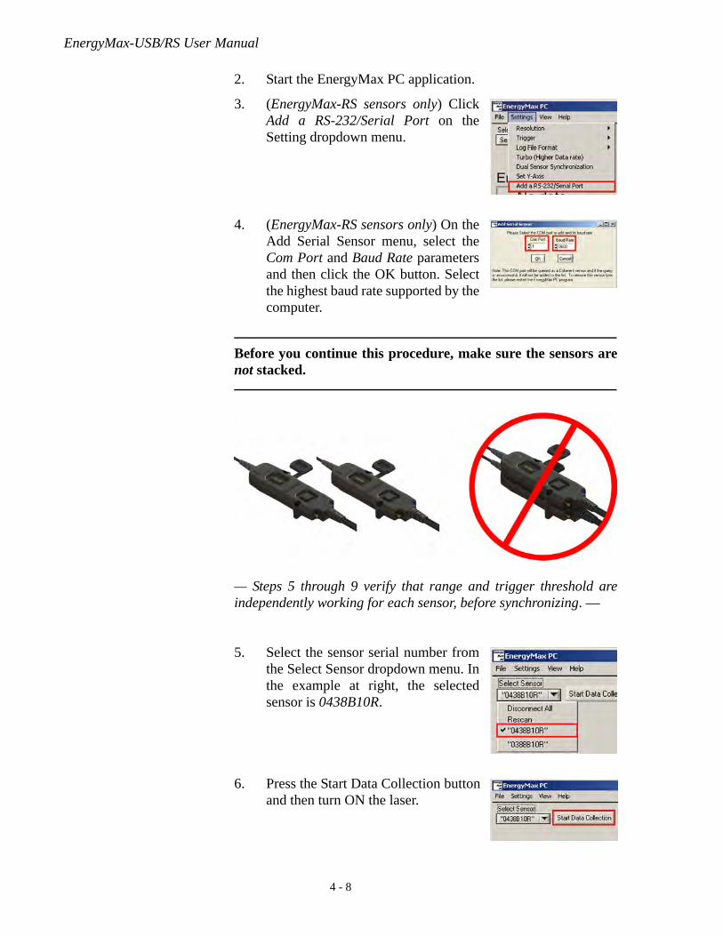
5. (EnergyMax-RS sensors only) ClickAdd a RS-232/Serial Port on theSetting dropdown menu.
6. (EnergyMax-RS sensors only) On theAdd Serial Sensor menu, select theCom Port and Baud Rate parametersand then click the OK button. Selectthe highest baud rate supported by thecomputer.
7. Select the sensor serial number fromthe Select Sensor dropdown menu. Inthe example at right, the selectedsensor is 0438B10R.
8. Press the Start Data Collection buttonand then turn ON the laser to starttaking energy measurements.
BlueLED
4 - 6

Operation
Tutorial: Synchronization
EnergyMax-USB and EnergyMax-RS sensors can be synchronizedfor greater accuracy when performing A/B ratiometry measure-ments. The purpose of synchronization mode is to make sure thatdata being reported by multiple sensors is correlated sequentiallywhen triggered by a common triggering event.
To do synchronization, EnergyMax-USB and -RS sensors aredesigned with the following features:
• The sensor units are stackable and automatically activate acommon trigger bus when stacked together.
• The electronics module on the bottom of the module stacktakes control of the trigger bus.
• Each measurement made during a trigger event is sequentiallynumbered.
Procedure: Taking a Synchronized A/B Ratiometric Reading
This procedure describes how to connect two EnergyMax-USB orEnergyMax-RS sensors to your PC and take a synchronized A/Bratiometric reading using the EnergyMax PC software.
WARNING!Follow all laser safety procedures. The lasers must be switchedOFF or shuttered before running the procedure given in thissection.
1. Connect the system components (the following figure showssystem components for both EnergyMax-USB and Ener-gyMax-RS sensors—select the one that’s applicable for yoursystem).
+4 to 20 VDC power supply
Meterless sensor power cable connector
RS-232 cable connector
Sensor cable
EnergyMax-RS System Components
Power supply cable connector
USB cable connector
Sensor cable
EnergyMax-USB System Components
4 - 7
EnergyMax-USB/RS User Manual
2. Start the EnergyMax PC application.
3. (EnergyMax-RS sensors only) ClickAdd a RS-232/Serial Port on theSetting dropdown menu.
4. (EnergyMax-RS sensors only) On theAdd Serial Sensor menu, select theCom Port and Baud Rate parametersand then click the OK button. Selectthe highest baud rate supported by thecomputer.
Before you continue this procedure, make sure the sensors arenot stacked.
— Steps 5 through 9 verify that range and trigger threshold areindependently working for each sensor, before synchronizing. —
5. Select the sensor serial number fromthe Select Sensor dropdown menu. Inthe example at right, the selectedsensor is 0438B10R.
6. Press the Start Data Collection buttonand then turn ON the laser.
4 - 8

Operation
7. Select the applicable MeasurementRange (High or Low) and adjust theTrigger Level to get a good measure-ment. For information on setting thetrigger level, refer to “Internal Trig-gering Mode” (p. 4-3).
8. Turn OFF the laser and confirm the sensor is not triggering onbaseline noise. If it is triggering on baseline noise, increase thetrigger level.
9. Repeat steps 5 through 8 for the second sensor and thencontinue to step 10, below.
10. Open the Select Sensor dropdown menu and select the “faster”sensor, that is, the sensor with the fastest (higher) repetitionrate specification.
11. Stack the sensors together, with the “faster” sensor located onthe bottom of the stack.
NOTICE!The “faster” sensor must be on the bottom of the stack to prop-erly trigger. Since the “faster” sensor gets a trigger first, it isimportant that this faster trigger be used to control the triggerbus.
12. Select Dual Sensor Synchronizationfrom the Setting dropdown menu.
13. Select the Synchronized Trending tab.
Slower sensoron top
Faster sensoron bottom
4 - 9

EnergyMax-USB/RS User Manual
14. Click the Setup button.
This will display the Sync ConfigurationSetup menu. The sensor selected in step 10,above (which is the faster of the twosensors), is automatically listed as Sensor 1(a) in this setup panel and will subsequentlybe listed as the “Master” serial number inthe Synchronized Trending chart.
15. Press the Select Sensor 2 button todisplay the Synch Configurationscreen.
This will display the Synch Configurationscreen.
16. Pick the second (slower) sensor fromthe dropdown menu and then press theOK button to return to the SynchConfiguration Setup screen.
4 - 10

Operation
17. Enter the desired math operation(default is an A/B ratiometric calcula-tion, which is shown in this example),and then click the OK button tocomplete setup.
18. Press the Reset button in the Frontpanel.
19. Click the Start Data Collection buttonand then turn ON the lasers.
20. View the ratiometric data beingtrended.
This data can be logged to a file using theLog Data to File dialog.
4 - 11

EnergyMax-USB/RS User Manual
Tutorial: Turbo Mode
At high repetition rates above approximately 1 to 2 kHz, the sensorcan capture and measure every single pulse, as well as send data tothe computer. Most dual-core and quad-core computers faster than 2GHz can process the data and analyze every pulse—even at highrepetition rates—using the full graphical and statistical features ofthe software. As the repetition rate increases, however, the softwarewill eventually reach a point at which it can miss some of the pulses.When that occurs, there are two options:
1. Enter a Decimation factor (a decimation factor of 2 sends 1/2of the data to the software, a decimation of 3 sends 1/3 of thedata, and so on).
2. Enter Turbo mode to log all of the data to a file.
Turbo mode lets the user continue to collect data for every pulse andsave it directly to a file at the fastest rate that the sensor will permit.This higher repetition rate logging capability is done by disablingthe calculation and display elements of the software, including thelive display, statistics and batch count, and plotting.
Procedure: Using Turbo Mode
This tutorial describes how to use the Turbo mode withinEnergyMax PC software.
WARNING!Follow all laser safety procedures. The lasers must be switchedOFF or shuttered before running the procedure given in thissection.
1. Connect the system components (the following figure showssystem components for EnergyMax-USB).
USB or RS-232cable connector
Sensor cable
Meterless sensorpower cable connector
EnergyMax-USB System Components
4 - 12

Operation
2. Start the EnergyMax PC application.
3. Select the sensor serial number fromthe Select Sensor dropdown menu. Inthe example at right, the selectedsensor is 0438B10R.
4. Select the applicable MeasurementRange (High or Low) and adjust theTrigger Level to get a good measure-ment. For information on setting thetrigger level, refer to “Internal Trig-gering Mode” (p. 4-3).
5. Click Turbo on the Setting dropdownmenu.
The Turbo Active - Display Inactive indicator light will turn green toindicate that the software is now in Turbo mode. Measured valueswill show “No data.”
Turbo Indicatorlight
4 - 13

EnergyMax-USB/RS User Manual
6. Press the Log Data to File folder icon.
7. When the directory screen appears,select/enter a file name (with a .txtextension for tab delimited or .csvextension for comma delimited), andthen press the OK button to dismissthe screen. In this example, theselected file is Turbo Log File.csv.
8. Click the OFF/ON button to turn ONdata logging.
9. Click the Start Data Collection buttonand then turn ON the laser.
During data collection in Turbo mode, all of the pulses are saved tothe log file and the Turbo Active - Display Inactive indicator blinksfor every 500 pulses collected.
All other front panel displays, including statistics, live display,batch counter, and the plot window, are inactive while Turbomode is active.
Using the Software
For complete EnergyMax PC information, refer to the software helpinside the application, or reference the EnergyMax PC Help fileincluded on the CD.
4 - 14
Special Topics
SPECIAL TOPICS
In this section:
• Understanding the external trigger circuit (this page)
• Extending cable length (p. 5-2)
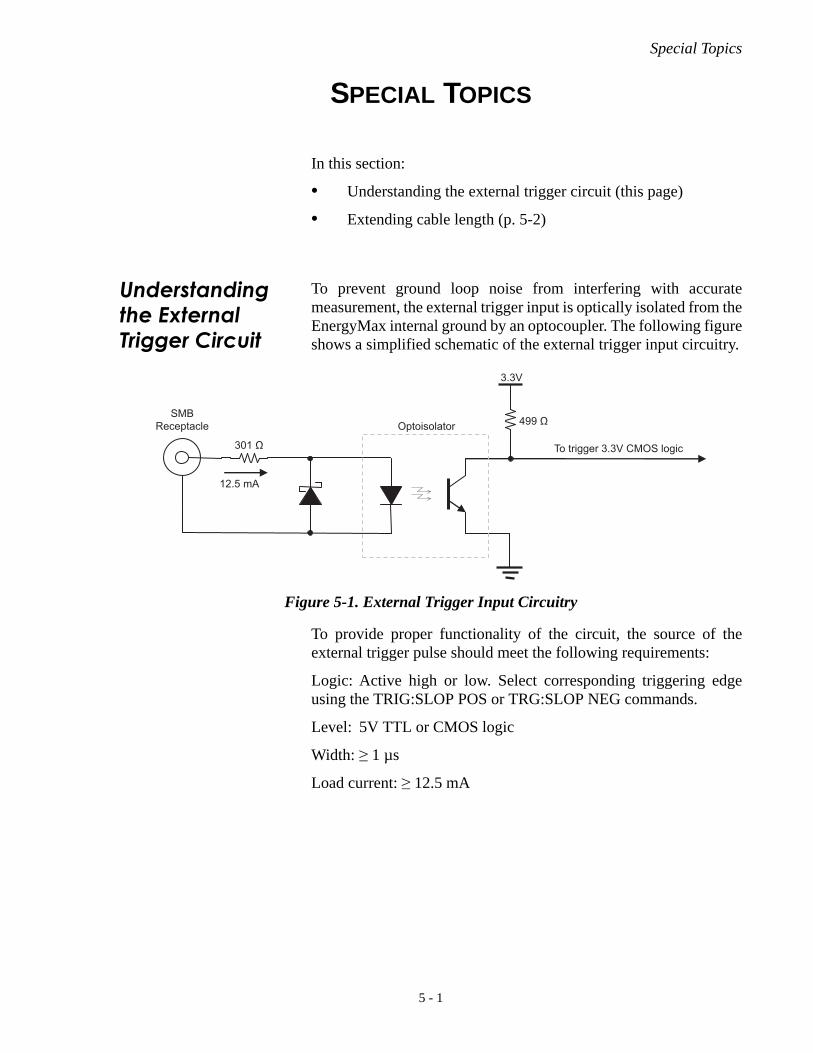
Understanding the External Trigger Circuit
To prevent ground loop noise from interfering with accuratemeasurement, the external trigger input is optically isolated from theEnergyMax internal ground by an optocoupler. The following figureshows a simplified schematic of the external trigger input circuitry.
To provide proper functionality of the circuit, the source of theexternal trigger pulse should meet the following requirements:
Logic: Active high or low. Select corresponding triggering edgeusing the TRIG:SLOP POS or TRG:SLOP NEG commands.
Level: 5V TTL or CMOS logic
Width: ≥ 1 µs
Load current: ≥ 12.5 mA
Figure 5-1. External Trigger Input Circuitry
Optoisolator SMB
Receptacle
3.3V
To trigger 3.3V CMOS logic
12.5 mA
5 - 1

EnergyMax-USB/RS User Manual
Extending Cable Length
USB sensors: The EnergyMax-USB cable is 3 meters in length fromthe sensor to the electronics module, and approximately 1 meter inlength from the electronics module to the USB or RS-232 connector.
USB hubs can be employed to increase the length of the cable. TheUSB standard permits a maximum of five hubs—connected in serieswith 5-meter cables connecting the hubs—thus providing amaximum range of 27.5 meters.
There are also active 5-meter USB extension cables on the marketthat perform as if they were a USB hub, but for just a single USBsensor. (Contact Coherent for advice related to specific hubs wehave tested in-house.)
RS sensors: Use a standard off-the-shelf RS-232 straight throughextension cable to increase the length.
Figure 5-2. EnergyMax-USB Standard Cable
3 meters (uncoiled length)
1 meter (uncoiled length)
5 - 2

Host Interface
HOST INTERFACE
In this section:
• Overview (this page)
• Message terminators (this page)
• Host command quick reference (p. 6-2)
• SCPI interface section (p. 6-4)
• Data streaming transmission interface section (p. 6-17)
• Operational parameters (p. 6-18)
• Host interface glossary (p. 6-18)
Overview This section defines the host interface of the EnergyMax-USB/RSmeterless energy sensor, and includes high-level commands,responses, and behavior that a user or host computer can expect fromthe sensor. The low-level interface—which covers RS-232, USB,and other types of communication methods—is not presented in thissection, except where it directly impacts the high-level interface.
Message Terminators
Messages between the sensor and the host computer are comprisedentirely of ASCII string characters, with the exception of the DataStreaming Transmission Interface, which sends unsolicited,uniquely coded out-of-band data transmissions. Strictly binarymessages are not supported. All message strings passing through thehost interface are terminated to signal the end of a message string.
Messages Received by the Sensor
Messages received by the sensor must be terminated by a carriagereturn (decimal 13). Line feed characters (decimal 10) are discarded,so message terminator flexibility can be attained. A command orquery is considered incomplete without the terminator. Themaximum length of any message received by the sensor is limited to200 bytes.
Messages Sent by the Sensor
All messages sent by the sensor and defined in this section are termi-nated by a carriage return and line feed pair.
6 - 1

EnergyMax-USB/RS User Manual
Host Command Quick Reference
The following table gives a brief description of all host commands.For detailed information about a specific command, go to the pagereferenced in the right-hand column.
Table 6-1. Host Command Quick Reference (Sheet 1 of 2)
Command Description Page #
SCPI INTERFACE
SCPI Common Commands
*RST Resets all operational parameters to their power-on states 6-4
*IDN? Queries the sensor identification string 6-5
System Options
SYSTem:RESTore Restores all user settings to the factory state 6-5
SYSTem:COMMunicate:HANDshaking Selects the state of SCPI message roundtrip handshaking 6-5
SYSTem:COMMunicate:HANDshaking? Queries the state of SCPI message roundtrip handshaking 6-5
SYSTem:COMMunicate:SERial:BAUD Selects the transmit and receive baud rates together when the device has an RS-232 serial host port
6-6
SYSTem:COMMunicate:SERial:BAUD? Queries the currently-selected baud rate 6-6
Error Record Reporting and Collection
SYSTem:ERRor:COUNt? Queries the number of error records in the error queue at the time of the query
6-7
SYSTem:ERRor:NEXT? Queries the next error record(s) in the error queue 6-7
SYSTem:ERRor:ALL? Queries all error records in the error queue at the time of the query
6-8
SYSTem:ERRor:CLEar Clears all error records in the error queue 6-8
Measurement Setup and Control
CONFigure:MEASure:TYPE Sets the meter measurement mode type 6-8
CONFigure:MEASure:TYPE? Queries the meter measurement mode type 6-8
CONFigure:MEASure:STATistics Sets the statistics processing mode 6-8
CONFigure:MEASure:STATistics? Queries the statistics processing mode 6-8
CONFigure:DECimation Sets the pulse decimation rate 6-9
CONFigure:DECimation? Queries the pulse decimation rate 6-9
CONFigure:DIAMeter Sets the aperture diameter 6-9
CONFigure:DIAMeter? Queries the aperture diameter 6-9
CONFigure:WAVElength Sets the current wavelength 6-9
CONFigure:WAVElength? Queries the current wavelength 6-9
CONFigure:GAIN:COMPensation Enables or disables gain compensation 6-10
CONFigure:GAIN:COMPensation? Queries the gain compensation setting 6-10
CONFigure:GAIN:FACTor Sets the gain compensation factor 6-10
CONFigure:GAIN:FACTor? Queries current gain compensation factor 6-10
CONFigure:RANGe:SELect Selects the meter measurement range 6-10
CONFigure:RANGe:SELect? Queries the meter measurement range 6-10
Statistics Mode Control
6 - 2

Host Interface
CONFigure:STATistics:BSIZe Sets the statistics batch size 6-11
CONFigure:STATistics:BSIZe? Queries the statistics batch size 6-11
CONFigure:STATistics:RMOde Selects the action to be taken at the end of a statistical batch 6-11
CONFigure:STATistics:RMOde? Queries the action to be taken at the end of a statistical batch 6-11
CONFigure:STATistics:STARt Terminates the current statistical batch and start a new one 6-11
CONFigure:STATistics:STOP Terminates the current statistical batch if a batch is in progress 6-11
Trigger Parameters
TRIGger:SOURce Selects the trigger source 6-12
TRIGger:LEVel Sets the trigger level 6-12
TRIGger:LEVel? Queries the trigger level 6-12
TRIGger:SLOPe Selects the external trigger edge 6-12
TRIGger:SLOPe? Queries the external trigger edge 6-12
TRIGger:DELay Selects the external trigger delay time 6-12
TRIGger:DELay? Queries the external trigger delay time 6-12
TRIGger:SEQuence Sets the sequence ID 6-13
TRIGger:BUS:PMODe {BUS|NBUS} Sets the trigger bus participation mode 6-13
TRIGger:BUS:PMODe? Queries the trigger bus participation mode 6-13
Measurement Data Collection
CONFigure:ITEMselect Selects the statistics mode of transmit data items 6-14
CONFigure:ITEMselect? Queries the statistics mode of transmit data items 6-14
CONFigure:STATistics:ITEMselect Selects the statistics mode of transmit data items 6-14
CONFigure:STATistics:ITEMselect? Queries the statistics mode of transmit data items 6-14
READ? Gets the last recorded measurement at the time of the query 6-14
Data Streaming Transmission Interface Gating
INITiate Enables data streaming interface transmission. 6-16
ABORt Disables data streaming interface transmission. 6-16
Sensor Information
SYSTem:INFormation:SNUMber? Queries the serial number 6-16
SYSTem:INFormation:PNUMber? Queries the part number 6-16
SYSTem:INFormation:MODel? Queries the model name 6-16
SYSTem:INFormation:CDATe? Queries the calibration date 6-16
SYSTem:INFormation:MDATe? Queries the manufacturing date 6-17
SYSTem:INFormation:WAVElength? Queries the default wavelength 6-17
Table 6-1. Host Command Quick Reference (Sheet 2 of 2)
Command Description Page #
6 - 3
EnergyMax-USB/RS User Manual
SCPI Interface Section
Syntax and Notation Conventions
Unless otherwise specified, all SCPI commands and queries followthe syntax and notation conventions specified by the SCPI Standard.For more information, refer to the SCPI Standard—found on the IVIFoundation website.
The base-10 numeric data format specification is used heavily in thissection. Unless otherwise specified, numeric data items are repre-sented as:
• Integer values
• Non-scientific notation floating point values
• Scientific notation floating point values (upper or lowercase E)
For example, the following data values are functionally equivalent:
• 31256
• 31256.0
• 3.1256E4
• 31.256E3
• +3.1256E+4.
Unless otherwise specified, non-numeric data items (typicallyreferred to as strings) are not quoted.
Enumerated values must exactly match, using the long form/shortform comparison rules defined under the SCPI Standard.
Commands and Queries
SCPI Common Commands
The SCPI Standard specifies a standard set of common commands.All common commands and queries start with an asterisk.
Reset Command - *RST
Resets all operational parameters to their power-on states. Resetdoes not affect calibration settings.
Command: *RST
Query: none
6 - 4

Host Interface
Identification Query - *IDN?
Queries the meter identification string, such as model name, firm-ware version, and firmware date.
Query: *IDN?Reply: “Coherent, Inc – EnergyMax” + <type> + “–” + <version> +“–” + <firmware date>
The dash sign separates all fields within the reply string. The firstfield is always "Coherent, Inc." The second field is the productname, "EnergyMax," plus the type ("USB" or "RS"). The third fieldis the version number, having the format"V<major>.<minor><optional qualifier characters>." The fourthfield is the firmware date, having the form "<3 character monthname> <day of the month> <year>." The reply string is not quoted.
Example identification string: “Coherent, Inc – EnergyMax -RS –V1.3 – Jul 10 2009” Note: The quotes are not transmitted.
System Options The system commands and queries access functionality that isexclusive of sensor measurement functions. These commands canbe sent at any time without affecting a measurement in progress.
System Restore
Restores all user settings to the factory state—refer to Table 6-6(p. 6-18).
Command: SYSTem:RESTore
Query: none
Message Handshaking
Selects the state of SCPI message roundtrip handshaking.
Command: SYSTem:COMMunicate:HANDshaking {ON|OFF}Reply: OK if ON is selected; otherwise, no reply is sent
Query: SYSTem:COMMunicate:HANDshaking?Reply: ON|OFF
If handshaking is ON:
• Empty commands (commands with only whitespace charac-ters) reply with “OK\r\n”
• Valid commands with valid data reply with “OK\r\n”
• Valid queries with valid data reply as explicitly defined else-where in this section, followed by “OK\r\n”
6 - 5

EnergyMax-USB/RS User Manual
• Valid commands or queries which result in an error reply with“ERR<n>\r\n,” where <n> is the error code number—refer to“Error Record Reporting and Collection” (p. 6-6).
• Unrecognized commands or queries reply with “ERR100\r\n”
• Error queuing occurs, as explicitly defined elsewhere in thissection
If handshaking is OFF:
• All command and query responses will behave as explicitlydefined elsewhere in this section.
Baud Rate
Selects the transmit and receive baud rates together when the devicehas an RS-232 serial host port. The command has no effect when thedevice has a USB host port. The query returns the currently selectedbaud rate.
Command: SYSTem:COMMunicate:SERial:BAUD {DEFault|9600|19200|38400|57600|115200}
Default: 9600
Query: SYSTem:COMMunicate:SERial:BAUD?Reply: 9600|19200|38400|57600|115200
If SCPI message handshaking is enabled, the new baud rate takeseffect after the handshake is transmitted. If SCPI message hand-shaking is disabled, the new baud rate takes effect immediately.
Error Record Reporting and Collection
Programming and system errors occasionally occur while testing ordebugging remote programs, and during measurement. Error stringsfollow the SCPI Standard for error record definition:
<error code>,<quoted error string>
The host queries for errors in two steps:
1. The host queries for the number of error records available (N).
2. The host queries N times for the error records.
Errors are stacked up to 20 deep. In the case of error overflow, thelast error in the error list is an indication of error overflow.
Possible error strings are shown in Table 6-2, below.
6 - 6
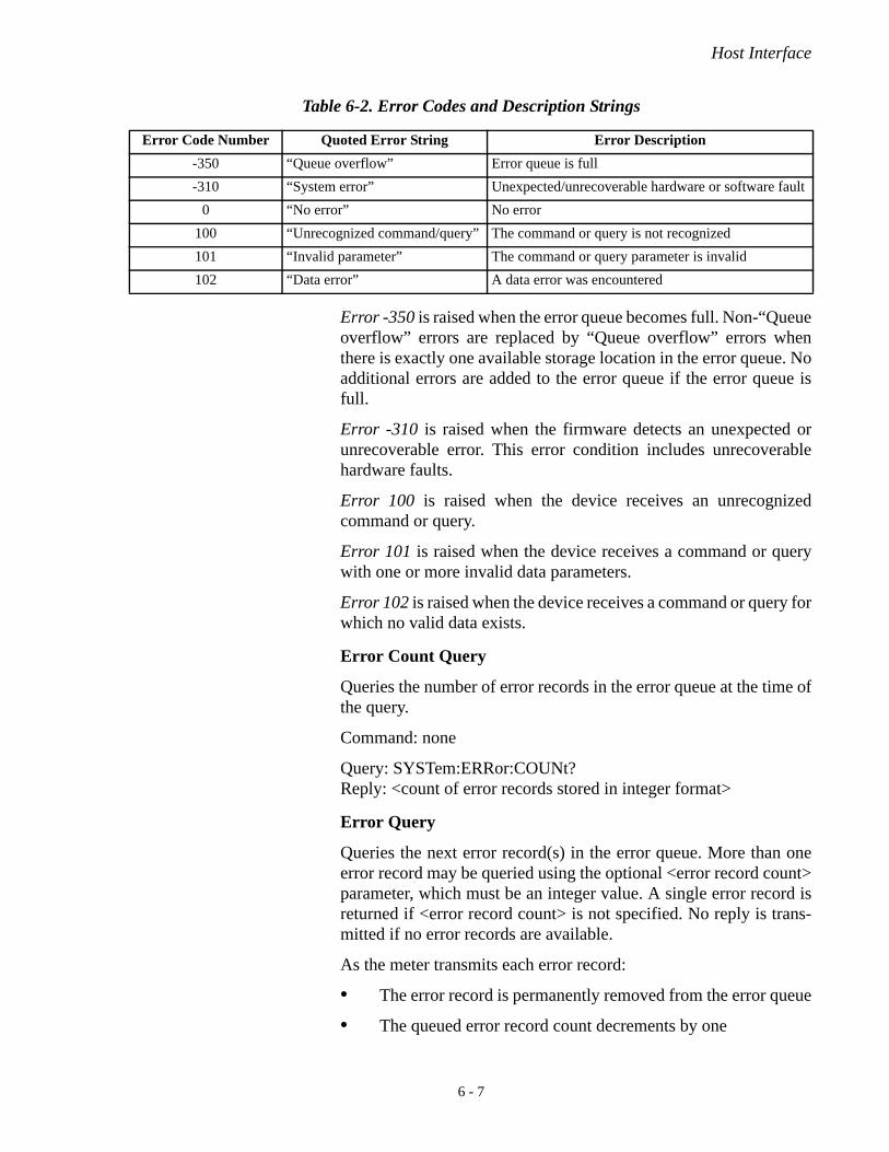
Host Interface
Error -350 is raised when the error queue becomes full. Non-“Queueoverflow” errors are replaced by “Queue overflow” errors whenthere is exactly one available storage location in the error queue. Noadditional errors are added to the error queue if the error queue isfull.
Error -310 is raised when the firmware detects an unexpected orunrecoverable error. This error condition includes unrecoverablehardware faults.
Error 100 is raised when the device receives an unrecognizedcommand or query.
Error 101 is raised when the device receives a command or querywith one or more invalid data parameters.
Error 102 is raised when the device receives a command or query forwhich no valid data exists.
Error Count Query
Queries the number of error records in the error queue at the time ofthe query.
Command: none
Query: SYSTem:ERRor:COUNt?Reply: <count of error records stored in integer format>
Error Query
Queries the next error record(s) in the error queue. More than oneerror record may be queried using the optional <error record count>parameter, which must be an integer value. A single error record isreturned if <error record count> is not specified. No reply is trans-mitted if no error records are available.
As the meter transmits each error record:
• The error record is permanently removed from the error queue
• The queued error record count decrements by one
Table 6-2. Error Codes and Description Strings
Error Code Number Quoted Error String Error Description
-350 “Queue overflow” Error queue is full
-310 “System error” Unexpected/unrecoverable hardware or software fault
0 “No error” No error
100 “Unrecognized command/query” The command or query is not recognized
101 “Invalid parameter” The command or query parameter is invalid
102 “Data error” A data error was encountered
6 - 7

EnergyMax-USB/RS User Manual
Command: none
Query: SYSTem:ERRor:NEXT? [<error record count>]Default: not applicable.Reply: <next available error record(s)>
All Error Query
Queries all error records in the error queue at the time of the query.No reply is transmitted if there are no error records available.
After completion of the reply transmission:
• The error queue is empty
• The queued error record count is zero
Command: none
Query: SYSTem:ERRor:ALL?Reply: <all available error record(s)>
All Error Clear
Clears all error records in the error queue.
Command: SYSTem:ERRor:CLEar
Query: none
Measurement Setup and Control
Measurement Mode
Sets the meter measurement mode to select either power (Watts) orenergy (Joules) measurement mode.
Command: CONFigure:MEASure {DEFault|J|W}Default: J (Joules) mode.
Query: CONFigure:MEASure:TYPE?Reply: J|W
Statistics Mode
This command sets the statistics processing mode to either off or on.
Command: CONFigure:MEASure:STATistics {DEFault|OFF|ON}Default: OFF
Query: CONFigure: MEASure:STATistics?Reply: OFF|ON
6 - 8

Host Interface
Variable Decimation
Sets the pulse decimation rate, which takes effect at the end of thecurrent decimation cycle. The decimation rate units are expressedpulses rounded to the nearest integer.
Pulse measurement data is selected for processing, ranging from asfrequent as 1 pulse processed per 1 measured, to as infrequently as1 pulse processed per 99999 measured. Pulse processing includesstatistics processing and transmission output.
Command: CONFigure:DECimation {DEFault|1..99999}Default: 1
Query: CONFigure:DECimation?Reply: 1..99999
Aperture Diameter
Sets the aperture diameter.
Command: CONFigure:DIAMeter <DEFault|aperture diameterin mm>
Default: 10 mm
Query: CONFigure:DIAMeter?Reply: <aperture diameter in mm>
Wavelength
Sets the current wavelength, which is committed to persistentstorage when it is changed. If the requested wavelength is greaterthan the upper wavelength limit, the current wavelength is set to theupper wavelength limit. Likewise, if the requested wavelength isless than the lower wavelength limit, the current wavelength is set tothe lower wavelength limit. The minimum and maximum allowedwavelength may also be named as data arguments. The query getsthe current maximum or minimum allowed wavelengths, dependingon the optional query data argument.
Command: CONFigure:WAVElength {MINimum| MAXimum|<requested wavelength in nm>}
Query: CONFigure:WAVElength? [MINimum|MAXimum]Reply (if [MINimum|MAXimum] is not specified): <granted
wavelength in nm>Reply (if MAXimum is specified): <allowed maximum wavelength
in nm> Reply (if MINimum is specified): <allowed minimum wavelength in
nm>
6 - 9

EnergyMax-USB/RS User Manual
Gain Compensation
Enable/Disable State
Enables or disables gain compensation, which is committed topersistent storage when it is changed.
Command: CONFigure:GAIN:COMPensation {DEFault|OFF|ON}Default: OFF
Query: CONFigure:GAIN:COMPensation?Reply: OFF|ON
Factor
Sets the gain compensation factor, which is committed to persistentstorage when it is changed. The gain compensation factor has nounits. Error 101 is raised if the gain compensation factor is less than0.001 or greater than 100,000.0.
Command: CONFigure:GAIN:FACTor {DEFault| <0.001..100000.0>}
Default: 1.0
Query: CONFigure:GAIN:FACTor?Reply: <gain compensation factor>
Range Select
Selects the meter measurement range, expressed in Joules. Ener-gyMax-USB and -RS sensors have two energy ranges: Maximum orhigh range, and Minimum or low range.
Range selection can be accomplished in two ways:
1. Express the maximum expected energy measurement in Joulesand the sensor firmware will select the best range.
2. Select either the maximum or minimum range from within theEnergyMax PC software.
The measurement range is selected by expressing the maximumexpected measurement, which must be greater than 0.0. The<granted full scale range> value is the lowest available full scalerange that can measure the <maximum expected measurement>. Forexample, if the list of available ranges is 3 mJ and 30 mJ, themaximum expected measurement is 10 mJ and the granted range is30 mJ. The <granted full scale range> is the top range available ifthe <maximum expected measurement> exceeds the top rangevalue. Using the MAX and MIN parameters on the query result inobtaining either the maximum full scale reading or the minimumrange full scale reading, respectively.
6 - 10

Host Interface
Command: CONFigure:RANGe:SELect {<maximum expected measurement>|MAXimum|MINimum}
Default: not applicable.
Query: CONFigure:RANGe:SELect? [MAXimum|MINimum]Reply: <granted full scale range>
Statistics Mode Control
Sets statistics calculation parameters to be used in the statistics oper-ating mode.
Batch Size
Sets the statistics batch size, which takes effect at the end of thecurrent statistical batch. The batch size units are pulses, rounded tothe nearest integer.
Command: CONFigure:STATistics:BSIZe {DEFault|2..1000000000}Default: 100
Query: CONFigure:STATistics:BSIZe?Reply: 2..99999
Restart Mode
Selects the action to be taken at the end of a statistical batch. Whenstatistics mode is on, selecting AUTomatic will begin a new batch atthe next measured pulse. Selecting MANual requires the startcommand to begin a new batch when statistics mode is on—refer tothe CONFigure:STATistics:STARt command under “Batch Initia-tion and Termination,” below.
Command: CONFigure:STATistics:RMOde {DEFault|MANual|AUTomatic}
Default: MANual
Query: CONFigure:STATistics:RMOde?Reply: MAN|AUT
Batch Initiation and Termination
Start a New Batch
Terminates the current statistical batch and starts a new one.
Command: CONFigure:STATistics:STARt
Query: none
The command is ignored if statistics mode is off.
Stop a Batch
6 - 11

EnergyMax-USB/RS User Manual
Terminates the current statistical batch if a batch is in progress.
Command: CONFigure:STATistics:STOP
Query: none
The command is ignored if statistics mode is off or a batch is not inprogress.
Trigger Parameters Trigger Source
Selects the trigger source.
Command: TRIGger:SOURce {DEFault|INTernal|EXTernal }Default: INTernal
Query: TRIGger:SOURce?Reply: INT|EXT
The trigger source setting has no effect on devices positioned asslaves in trigger-bussed configurations. All slaves receive their trig-gers from the trigger bus.
Internal Trigger
Level
Sets the trigger level expressed as a percentage of full-scale capa-bility.
Command: TRIGger:LEVel {DEFault|0.01..30.0}Default: 5
Query: TRIGger:LEVel?Reply: 0.01..30.0
The trigger level setting has no effect when external triggering isselected, or on devices positioned as slaves in trigger-bussed config-urations. All slaves receive their triggers from the trigger bus.
External Trigger
The external trigger settings has no effect when internal triggering isselected, or on devices that are positioned as slaves in trigger-bussedconfigurations.
Edge Select
Selects the external trigger edge. The selected trigger edge is theexternal trigger event.
Command: TRIGger:SLOPe {DEFault|POSitive|NEGative}Default: POSitive
6 - 12

Host Interface
Query: TRIGger:SLOPe?Reply: POS|NEG
Delay
Selects the external trigger delay time. The internal trigger happensat the time marked by the external trigger delay time after theselected external trigger edge. The trigger delay time units aremicroseconds.
Command: TRIGger:DELay {DEFault|0..1000}Default: 0
Query: TRIGger:DELay?Reply: 0..1000
Set Sequence ID
Sets the sequence ID, which must be an integer value.
The sequence ID is used for data synchronization of multiple meterssharing the same trigger signal.
Command: TRIGger:SEQuence {DEFault|0..16777215}Default: 0
Query: none
Trigger Bus
Sets the trigger bus participation mode, that is, bussed or not bussed.The query gets the trigger bus participation mode.
Command: TRIGger:BUS:PMODe {BUS|NBUS}
Query: TRIGger:BUS:PMODe?Reply: BUS|NBUS
This commend is used to designate if the device participates in thetrigger bus. The designated mode must match the physical triggerbus configuration.
Bus Control Position
Gets the trigger bus control position, that is, master or slave.
Command: None
Query: TRIGger:BUS:POSition?Reply: MAST|SLAV
Bus position is determined by the physical position of devicesstacked in a trigger bus configuration, which is one master and oneor more slaves. Unbussed devices will always return MAST.
6 - 13
EnergyMax-USB/RS User Manual
Measurement Data Collection
Measurement data can be collected in two ways:
1. Configuring the data item select and receiving measurementdata records from the Data Streaming Transmission Interface.
2. Querying the last data record generated
Data Item Select
Data items that appear in a measurement data record are selectable.Selections differ, based on measurement and statistics modes.
Statistics Mode Off
Selects the statistics mode of transmit data items, which takes effectimmediately if statistics mode is off. The data argument is acomma-separated list of one or more tokens shown below. At leastone token must be specified. The tokens may be specified in anyorder.
Command: CONFigure:ITEMselect {PULS,PER,FLAG,SEQ}
Query: CONFigure:ITEMselect?Reply: one or more of PULS|PER|FLAG|SEQ
Statistics Mode On
Selects the statistics mode of transmit data items, which takes effectat the end of the current statistical batch if statistics mode is on. Thedata argument is a comma-separated list of one or more tokensshown below. At least one token must be specified. The tokens maybe specified in any order.
Command: CONFigure:STATistics:ITEMselect {MEAN,MIN,MAX,STDV,DOSE,MISS,SEQ}
Query: CONFigure:STATistics:ITEMselect?Reply: one or more of MEAN,MIN,MAX,STDV,DOSE,MISS,SEQ
Last Data Record Query
Gets the last recorded measurement at the time of the query. Noreply is transmitted if no measurement has been recorded.
Command: none
Query: READ?Reply: <last measurement record>
The last measurement record is composed of comma-delimited dataitems generated at the same instant. The data items presented—including a flags item—vary, depending on the measurement andstatistics modes and the data items selected, as shown in Table 6-3and Table 6-4, below.
6 - 14

Host Interface
<power> is expressed in Watts, using the “%.3E” C formatting spec-ification.
<energy> and <dose> are expressed in Joules, using the “%.3E” Cformatting specification.
<period> is expressed in integer microseconds.
<missed> is expressed in integer units
<sequence ID> is expressed in integer dimensionless units.
Statistics data items are the same units as the power or energymeasurements from which they were calculated. The <power>,<mean>, <min>, <max>, <stdv>, and <dose> data items are zero ifany constituent pulse measurement in the batch is not measureabledue to an error (for example, peak or baseline clipping).
The <flags> data item, which communicates qualification informa-tion, is reported with each data message. Qualification information,which includes various error conditions, is reported in a stringcontaining one ASCII character for each qualification that isasserted. If the qualification character is present, the qualification isasserted. If the qualification condition character is absent, the quali-fication is not asserted. Each character present has a uniquemeaning, as described in the following table.
Table 6-3. Measurement Data Record Formats—Statistics Mode Off
Measurement Mode Measurement Record Format
Watts <power>,<period>,<flags>,<sequence ID>
Joules <energy>,<period>,<flags>,<sequence ID >
Table 6-4. Measurement Data Record Formats—Statistics Mode On
Measurement Mode Measurement Record Format
Watts <power>,<mean>,<min>,<max>,<stdv>,<dose>,<missed>,<flags>,<sequence ID>
Joules <energy>,<mean>,<min>,<max>,<stdv>,<dose>,<missed>,<flags>,<sequence ID>
Table 6-5. Flag Character Definitions
Qualification Character Qualification Meaning
P Peak clip error (statistics mode off only)
B Baseline clip error (statistics mode off only)
M Missed pulse (external trigger only, statistics mode off only)
D Dirty batch (statistics mode on only)
0 (zero) No qualification exists
6 - 15

EnergyMax-USB/RS User Manual
Data Streaming Transmission Interface Gating
The host has control over when measurement data is transmittedfrom the data streaming transmission interface. Transmission isenabled after an INITiate command. Transmission is disabled afteran ABORt command. While transmission is enabled, measurementdata records are transmitted immediately as they are generated.
Initiate Command
Enables data streaming interface transmission. This command isignored if data streaming interface transmission is already enabled.
Command: INITiate
Query: none
Abort Command
Disables data streaming interface transmission. This command isignored if data streaming interface transmission is already disabled.
Command: ABORt
Query: none
Sensor Information The sensor can be queried for information for the purposes of unitidentification and quality control.
Serial Number
The query, which is always available, gets the serial number.
Query: SYSTem:INFormation:SNUMber?Reply: <quoted serial number>
Part Number
The query, which is always available, gets the serial number.
Query: SYSTem:INFormation:PNUMber?Reply: <quoted part number>
Model Name
The query, which is always available, gets the model name.
Query: SYSTem:INFormation:MODel?Reply: <quoted model name>
Calibration Date
The query, which is always availale, gets the calibration date.
Query: SYSTem:INFormation:CDATe?Reply: <quoted calibration date>
6 - 16

Host Interface
Manufacturing Date
The query, which is always available, gets the manufacturing date.
Query: SYSTem:INFormation:MDATe?Reply: <quoted calibration date>
Default Wavelength
The query, which is always available, gets the default wavelength.
Query: SYSTem:INFormation:WAVElength?Reply: <default wavelength in nm>
Calibration All commands and queries contained in this section are used exclu-sively by the factory for calibration purposes. Error 100 will beraised if a valid password has not sent since the last reset cycle if anycommand or query contained in this section except the passwordcommand is received.
Data Streaming Transmission Interface Section
The Data Streaming Transmission Interface is an out-of-band inter-face in which data messages are transmitted from the sensor to thehost only. Gating of the data streaming transmissions is controlledby the INITiate/ABORt command, described under “Data StreamingTransmission Interface Gating” (p. 6-16).
Data streaming transmission messages are ASCII formatted, but notstrictly. The high bit (mask 0x80)—which is always set for all bytesof all data streaming transmission messages, including the termina-tors—allows host software to easily differentiate between datastreaming transmission messages and SCPI reply messages. Thehost may operate using the rule that if the high bit is set on any bytereceived from the sensor, it is part of a data streaming transmissionmessage.
Data streaming transmission messages are immediately sent to thehost in ASCII text form as pulse measurements are generated. Eachmessage conforms to the last measurement data record format—asdescribed under “Last Data Record Query” (p. 6-14)—but with thehigh bit set in all transmitted bytes.
6 - 17
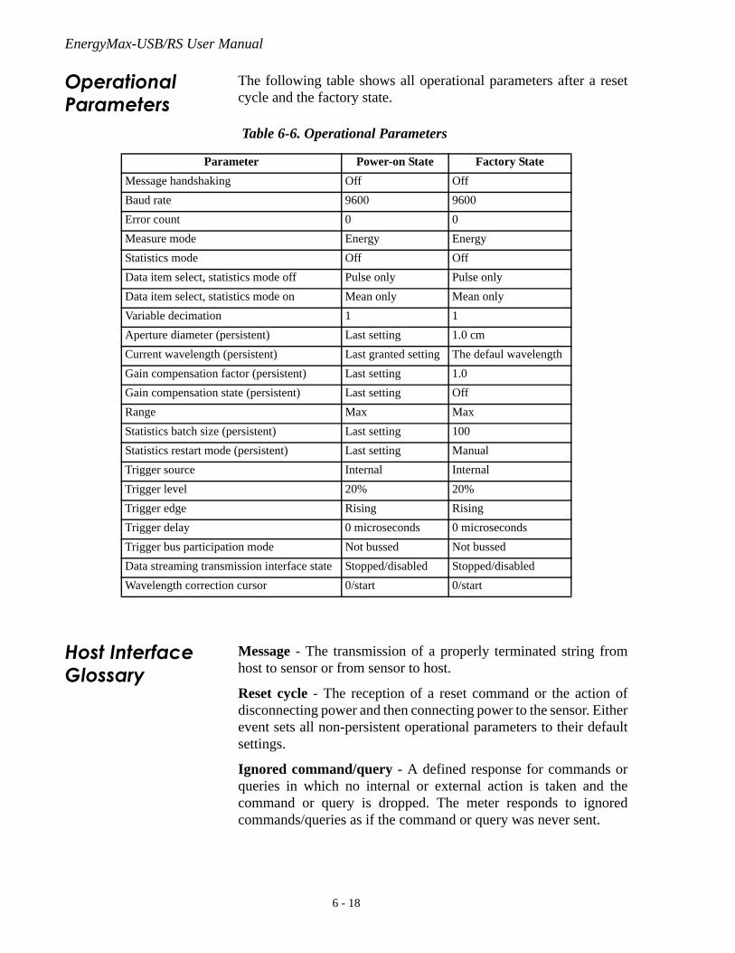
EnergyMax-USB/RS User Manual
Operational Parameters
The following table shows all operational parameters after a resetcycle and the factory state.
Host Interface Glossary
Message - The transmission of a properly terminated string fromhost to sensor or from sensor to host.
Reset cycle - The reception of a reset command or the action ofdisconnecting power and then connecting power to the sensor. Eitherevent sets all non-persistent operational parameters to their defaultsettings.
Ignored command/query - A defined response for commands orqueries in which no internal or external action is taken and thecommand or query is dropped. The meter responds to ignoredcommands/queries as if the command or query was never sent.
Table 6-6. Operational Parameters
Parameter Power-on State Factory State
Message handshaking Off Off
Baud rate 9600 9600
Error count 0 0
Measure mode Energy Energy
Statistics mode Off Off
Data item select, statistics mode off Pulse only Pulse only
Data item select, statistics mode on Mean only Mean only
Variable decimation 1 1
Aperture diameter (persistent) Last setting 1.0 cm
Current wavelength (persistent) Last granted setting The defaul wavelength
Gain compensation factor (persistent) Last setting 1.0
Gain compensation state (persistent) Last setting Off
Range Max Max
Statistics batch size (persistent) Last setting 100
Statistics restart mode (persistent) Last setting Manual
Trigger source Internal Internal
Trigger level 20% 20%
Trigger edge Rising Rising
Trigger delay 0 microseconds 0 microseconds
Trigger bus participation mode Not bussed Not bussed
Data streaming transmission interface state Stopped/disabled Stopped/disabled
Wavelength correction cursor 0/start 0/start
6 - 18

Host Interface
Factory settings - Persistent settings typically set by the manufac-turer. They are parameters whose access is restricted by password.Factory settings do not include operational parameters.
Missed pulse - A measured pulse that registers with a peak valuethat does not exceed the baseline value. Missed pulses are detectableonly under external trigger conditions.
6 - 19

EnergyMax-USB/RS User Manual
6 - 20

Calibration
CALIBRATION AND WARRANTY
In this section:
• Coherent calibration facilities and capabilities (this page)
• Optical calibration method (p. 7-2)
• Limited warranty (p. 7-3)
• Extended warranty (p. 7-4)
• Warranty limitations (p. 7-4)
• Obtaining service (p. 7-5)
• Product shipping instructions (p. 7-6)
Coherent Calibration Facilities and Capabilities
As the largest laser manufacturer in the world, Coherent has beenable to build state-of-the-art calibration facilities containing thewidest possible range of laser types and technologies. This enablesus to perform instrument and sensor calibration under virtually anycombination of wavelength, power, and operating characteristics.Sensors are calibrated against NIST-traceable working standardsensors which are, in turn, calibrated against NIST-calibrated goldenstandard sensors. These working and golden standards are main-tained with the utmost care, recalibrated annually, and verified evenmore regularly. We maintain multiple NIST-calibrated standards atmany laser wavelengths to support the growing calibration needs ofour customers. Optical calibration is a core competency at Coherentand we strive to continually improve our methods, precision, andrepeatability. Additionally, most of the calibrations are performedwith highly automated systems, thus reducing the possibility ofhuman error to nearly zero. Strict quality inspections during manystages of calibration and testing assure a precise and accurate instru-ment that is NIST traceable and CE marked. The benefit to ourcustomers is that instruments calibrated by Coherent will consis-tently perform as expected under their actual use conditions. We area registered ISO 9001:2000 company, our products are NIST trace-able, and our calibration labs are fully ANSI Z540 compliant.
In addition to the technological advantage, we also strive to deliverthe best service in the industry, with a knowledgeable and responsivestaff, and rapid turnaround.
7 - 1

EnergyMax-USB/RS User Manual
Optical Calibration Method
EnergyMax NIST Traceable Optical Calibration
Coherent provides a NIST (U.S. National Institute of Standards andTechnology) traceable calibration certificate with every sensor thatis shipped.
The calibration factor of an EnergyMax-USB/RS energy sensorspecifies the magnitude of the pulse output for one joule opticalinput.
Re-certify Once a Year
Coherent laser power and energy meters are precision instruments,capable of delivering very accurate measurements as well asproviding many years of useful service. To maintain this high levelof performance, and to ensure compliance with your quality and ISOcertification, it is important to have your measurement systemserviced and re-certified once per year.
Extended use of laser power and energy meters and sensors, as wellas environmental factors, can have an adverse effect on accuracy andcan also result in wear and/or damage to parts critical to maintainingoptimum performance.
Calibration Fundamentals
EnergyMax-USB/RS sensors contain the analog-to-digital conver-sion, peak detection, and gain stages integrated into the sensor cable.The electronics and sensor are calibrated together as a system, usingthe following calibration principles.
Coherent performs an optical calibration using a ratiometric substi-tution method to remove laser energy variation as a source of errorand to eliminate dependence on the absolute value of the beamsplitter ratio, as diagrammed in the figure shown below.
By introducing a beamsplitter, each laser pulse can impinge on twosensors and the ratio of two sensor outputs can be measured on eachpulse. This ratio is independent of the actual pulse energy.
7 - 2

Calibration
The actual calibration involves calculating ratios with respect to thereference sensor for the working standard and then for the UnitUnder Test (UUT).
To produce a ratio, a sample comprised of 15 seconds of data is takenand then averaged, and is then used to calculate the final calibrationfactor.
Calibration Verification
After calibration, each sensor is tested to verify the calibration. Theresult of this verification is presented on the second page. Eachsensor contains two gain stages. Each stage is calibrated and testedin this manner.
Limited Warranty
Coherent, Inc. (the “Company”) warrants its laser power and energymeters and sensors products (“Products”) to the original purchaser(the “Customer”) that the product is free from defects in materialsand workmanship and complies with all specifications, active at thetime of purchase, for a period of twelve (12) months.
Coherent, Inc. will, at its option, repair or replace any product orcomponent found to be defective during the warranty period. Thiswarranty applies only to the original purchaser and is not transfer-able.
Figure 7-1. Ratiometric Method of Optical Calibration
U.U.TLaser
ReferenceSensor
WorkingStandard
Does not dependon splitter
7 - 3

EnergyMax-USB/RS User Manual
Extended Warranty
Coherent, Inc. (the “Company”) offers original purchasers (the“Customer”) purchasing laser power and energy meters and sensorsproducts (“Products”) an extended twelve (12) month warrantyprogram, which includes all parts and labor. In order to qualify forthis warranty, a Customer must return the Product to the Companyfor recalibration and recertification. The Company will re-certify theProduct, provide software upgrades, and perform any neededrepairs, and recalibrate the Product, for a fixed service fee (as estab-lished by the Company from time to time and in effect at the time ofservice). If the product cannot be re-certified due to damage beyondrepair, parts obsolescence, or other reasons, the Customer may beinformed that an Extended Warranty program is not available for theProduct.
If the Product fails and is returned to the Company within one yearfollowing the date of recalibration and recertification service, theCompany will, at its option, repair or replace the Product or anycomponent found to be defective. If the Product must be replacedand the Product is no longer available for sale, Coherent reserves theright to replace with an equivalent or better Product. This warrantyapplies only to the original purchaser and is not transferable.
Warranty Limitations
The foregoing warranties shall not apply, and Coherent reserves theright to refuse warranty service, should malfunction or failure resultfrom:
• Damage caused by improper installation, handling or use.
• Laser damage (including sensor elements damaged beyondrepair).
• Failure to follow recommended maintenance procedures.
• Unauthorized product modification or repair.
• Operation outside the environmental specifications of theproduct.
Coherent assumes no liability for Customer-supplied materialreturned with Products for warranty service or recalibration.
THIS WARRANTY IS EXCLUSIVE IN LIEU OF ALL OTHERWARRANTIES WHETHER WRITTEN, ORAL, OR IMPLIED.COHERENT SPECIFICALLY DISCLAIMS THE IMPLIEDWARRANTIES OF MERCHANTABILITY AND FITNESS FORA PARTICULAR PURPOSE. IN NO EVENT SHALL THECOMPANY BE LIABLE FOR ANY INDIRECT, INCIDENTALOR CONSEQUENTIAL DAMAGES IN CONNECTION WITHITS PRODUCTS.
7 - 4

Calibration
Obtaining Service
In order to obtain service under this warranty, Customer must notifythe Company of the defect before the expiration of the warrantyperiod and make suitable arrangements for the performance ofservice. The Company shall, in its sole discretion, determinewhether to perform warranty service at the Customer's facility, at theCompany's facility or at an authorized repair station.
If Customer is directed by the Company to ship the product to theCompany or a repair station, Customer shall package the product (toprotect from damage during shipping) and ship it to the addressspecified by the Company, shipping prepaid. The customer shall paythe cost of shipping the Product back to the Customer in conjunctionwith recalibration and recertification; the Company shall pay thecost of shipping the Product back to the Customer in conjunctionwith product failures within the first twelve months of time of saleor during an extended twelve month warranty period.
A Returned Material Authorization number (RMA) assigned by theCompany must be included on the outside of all shipping packagesand containers. Items returned without an RMA number are subjectto return to the sender.
For the latest Customer Service information, refer to our website:www.Coherent.com.
Detailed instructions on how to prepare a product for shipping aredescribed under “Product Shipping Instructions” (p. 7-6)
Table 7-1. Coherent Service Centers
Location Phone Fax E-mail
USA 1.800.343.4912 503.454.5777 [email protected]
Europe +49-6071-968-0 +49-6071-968-499 [email protected]
International 503.454.5700 503.454.5777 [email protected]
7 - 5

EnergyMax-USB/RS User Manual
Product Shipping Instructions
To prepare the product for shipping to Coherent:
1. Contact Coherent Customer Service—refer to Table 7-1(p. 7-5)—for a Return Material Authorization number.
2. Attach a tag to the product that includes the name and addressof the owner, the person to contact, the serial number, and theRMA number you received from Coherent Customer Service.
3. Position the protective cap over the sensor.
4. Place the sensor in the original shipping carton and then situatethe foam cutout over the sensor to hold it in place during ship-ment.
If the original packing material and shipping carton are notavailable, obtain a corrugated cardboard shipping carton withinside dimensions that are at least 6 in. (15 cm) taller, wider,and deeper than the sensor. The shipping carton must beconstructed of cardboard with a minimum of 375 lb. (170 kg)test strength. Wrap the sensor with polyethylene sheeting orequivalent material and then cushion the sensor in the shippingcarton with packing material or urethane foam on all sidesbetween the carton and the sensor. Allow 3 in. (7.5 cm) on allsides, the top, and the bottom.
5. Seal the shipping carton with shipping tape or an industrialstapler.
6. Ship the product to:
Coherent, Inc.27650 SW 95th Ave.Wilsonville, OR 97070Attn: RMA # (add the RMA number you received fromCoherent Customer Service)
7 - 6

Frequently Asked Questions
APPENDIX A: FREQUENTLY ASKED QUESTIONS
This appendix gives answers to common questions about CoherentEnergyMax sensors.
Q: What if I exceed the average power specification?
A: Use of a sensor beyond its average power specification willresult in increased error, and can result in damage to the sensorif the temperature gets too hot. Optional EnergyMax heatsinksare available to increase the average power specification ofcertain sensors (for more information about heatsinks—referto “Increasing Average Power With Heatsinks” (p. 3-1).
NOTICE!Use of EnergyMax sensors at average power levels beyond thebase model average power specification—without the optionalheatsink—can cause permanent damage to the sensor.
Q: What if I exceed the repetition rate specification?
A: Use of EnergyMax sensors beyond the repetition rate spec-ification will result in additional measurement error. Increasedrepetition rate also increases the average power, so do notapply more average power than can be handled by the sensor.
Q: What if I exceed the maximum energy specification?
A: EnergyMax sensors have an active circuit that will saturateif the applied energy is too high. There is some headroomabove the maximum specification (the amount of headroom isdependent on sensor responsivity and varies from 5 to 25%,depending on the individual sensor), but the maximum levelshould not be exceeded. Another implication of using a sensorabove its rated energy is the potential of high energy densitydamaging the coating.
Q: What if I exceed the pulse width specification?
A: Although there is some headroom built into the specifica-tion, using an EnergyMax sensor with a laser that has a pulsewidth longer than the specified maximum pulse width willresult in increased measurement error. For example, if you usethe sensor with double the maximum pulse width, the resultwill be an additional 2 to 3% error.
A - 1
EnergyMax-USB/RS User Manual
Q: Why isn’t there a minimum pulse width specification?
A: These pyroelectric energy sensors can function with pulsewidths as short as nanoseconds, picoseconds, or even femto-seconds, and still measure correctly. As described in theprevious answer, the maximum pulse width specification isimportant and is limited by the fall time of the sensor, soCoherent only specs the maximum—not the minimum—pulsewidth. As the pulse width gets shorter, the only change thatoccurs is that the damage threshold on the energy sensorsdecreases. When using really short pulses, pay close attentionto the damage threshold specifications and make use of thedamage test slide.
Q: Can I use the sensor at a wavelength different from the one it wascalibrated at?
A: Yes. EnergyMax sensors have a wavelength compensationtable in the circuitry inside the sensor. Plug the sensor into yourmeter and go to the wavelength setup. Enter the wavelength ofyour laser and the sensor will correct for any spectral and/ortransmission changes due to wavelength—refer to Figure 3-3(p. 3-7) for more information.
A - 2

Index
INDEX
AActive area diameter 2-4ANSI Z540 7-1Average power
Increasing with heatsinks 3-1Linearity 3-4Ratings 3-2Specification 8-1
CCable length 2-4Cable length, extending 5-2Calibration
Facilities and capabilities 7-1Fundamentals 7-2Uncertainty 2-4Verification 7-3Wavelength 2-4
Calibration and warranty 7-1Coherent calibration facilities and capabilities 7-1Extended warranty 7-4Limited warranty 7-3Obtaining service 7-5Optical calibration method 7-2Product shipping instructions 7-6Warranty limitations 7-4
CoherentCalibration facilities and capabilities 7-1Service centers 7-5
ComplianceRoHS 1-1
DDamage
Test slide xThresholds 3-3
Declaration of Conformity 1-2Description 2-1
Post and stand assembly xUnpacking and inspection ix
Diffuse metallic EnergyMax sensors 2-5
EEnergy
Linearity 3-4Range 2-4
EnergyMax NIST traceable optical calibration 7-2EnergyMax sensors
Diffuse metallic 2-5
MaxBlack 2-4MaxBlack with diffusers 2-6MaxUV 2-7Quantum 2-8
Environmental regulations 1-1RoHS compliance 1-1Waste Electrical and Electronic Equipment (WEEE,
2002) 1-1Extended warranty 7-4
FFrequently asked questions 8-1
HHeat sinks 3-1Host interface 6-1
IIncreasing average power with heatsinks 3-1Interface
Host 6-1ISO 9001:2000 7-1Item/part numbers 2-4
LLabel, Waste Electrical and Electronic Equipment
(WEEE, 2002) 1-1LED status indicators 4-1, 5-1Limited warranty 7-3Linearity 3-4
MMaxBlack coating 2-4MaxBlack EnergyMax sensors 2-4MaxBlack EnergyMax sensors with diffusers 2-6Maximum
Average power 2-4Energy 8-1Energy density 2-4Pulse width 2-4Repetition rate 2-4
MaxUV EnergyMax sensors 2-7Measurement linearity 3-4
Average power 3-4Energy 3-4Pulse width 3-5Repetition rate 3-4
MessagesReceived by the sensor 6-1Sent by the sensor 6-1
Index - 1

EnergyMax-USB/RS User Manual
NNIST traceability 7-1Noise equivalent energy 2-4
OObtaining service 7-5Operating the software 4-1Optical calibration
Method 7-2Ratiometric method 7-3
Optical calibration methodCalibration fundamentals 7-2Calibration verification 7-3EnergyMax NIST traceable optical calibration 7-2Re-certify once a year 7-2
PPost and stand assembly xPower measurements, taking 4-5Preface viiProduct overview
Diffuse metallic EnergyMax sensors 2-5MaxBlack EnergyMax sensors 2-4MaxBlack EnergyMax sensors with diffusers 2-6MaxUV EnergyMax sensors 2-7Quantum EnergyMax Sensors 2-8
Product shipping instructions 7-6Publication updates ixPulse width
Linearity 3-5Specification 8-1
PyroelectricCurrent and voltage response 3-3Technology 3-2
QQuantum EnergyMax sensors 2-8
RRatiometric method of optical calibration 7-3Re-certify once a year 7-2Repetition rate
Linearity 3-4Specification 8-1
Response, spectral 3-5Return material authorization number (RMA) 7-6RoHS compliance 1-1
RS sensors, powering 4-2
SSafety 1-1
Declaration of Conformity 1-2Environmental regulations 1-1
Service, obtaining 7-5Shipping instructions, product 7-6Specifications
Diffuse metallic EnergyMax sensor 2-5MaxBlack EnergyMax sensor 2-4MaxBlack EnergyMax sensor with diffuser 2-6MaxUV EnergyMax sensor 2-7
SpectralAbsorption of EnergyMax sensor coatings 3-7Response 3-5Sensitivity of EnergyMax sensors with
diffusers 3-8Status indicators, LED 4-1, 5-1Symbols used in this document vii
TTechnical description 3-1
Damage thresholds 3-3Increasing average power with heat sinks 3-1Measurement linearity 3-4Pyroelectric technology 3-2Spectral response 3-5
Technology, pyroelectric 3-2
UUnpacking and inspection ix
WWarranty
Extended 7-4Limitations 7-4Limited 7-3
Waste Electrical and Electronic Equipment (WEEE, 2002) 1-1
WavelengthCompensation 3-6, 8-2Compensation accuracy 3-6Range 2-4
Wavelength, setting 4-14
Index - 2


EnergyMax -USB/RS User Manual©Coherent, Inc., 3/2015 (RoHS), printed in the USAPart No. 1186243 Rev. AB
TM