energyplus programming standard - infohouseinfohouse.p2ric.org/ref/36/35829.pdf · fortran 90/95...
TRANSCRIPT
ENERGYPLUS™
COPYRIGHT © 1996-2005 THE BOARD OF TRUSTEES OF THE UNIVERSITY OF ILLINOIS AND THE REGENTS OF THE UNIVERSITY OF CALIFORNIA THROUGH THE ERNESTO ORLANDO LAWRENCE BERKELEY NATIONAL LABORATORY. ALL RIGHTS RESERVED. NO PART OF THIS MATERIAL MAY BE REPRODUCED OR TRANSMITTED IN ANY FORM OR BY ANY MEANS WITHOUT THE PRIOR WRITTEN PERMISSION OF THE UNIVERSITY OF ILLINOIS OR THE ERNEST ORLANDO LAWRENCE BERKELEY NATIONAL LABORATORY. ENERGYPLUS IS A TRADEMARK OF THE US DEPARTMENT OF ENERGY.
EnergyPlus Programming Standard
(to understand and be able to write the code)
Date: April 21, 2005

TABLE OF CONTENTS
Introduction ...................................................................................................................1
Reference Documents..................................................................................................2
Coding Standard...........................................................................................................3
FORTRAN90/95.............................................................................................. 3
FORTRAN90 Code ................................................................................... 3
F90/95 Language Features for Use in EnergyPlus ................................... 5
FORTRAN90/95 Compilers....................................................................... 5
Beyond F90/95 Language Features for Use in EnergyPlus...................... 6
Naming Conventions....................................................................................... 6
Subroutine Naming Convention ................................................................ 6
Module and Source Code File Naming Convention .................................. 7
Variable Naming Convention .................................................................... 7
Program Variables .......................................................................................... 8
Variable Declarations and Usage.............................................................. 8
Units in EnergyPlus................................................................................... 9
Table 1. Standard Units for EnergyPlus. .............................................. 9
Variable Initializations ............................................................................. 10
Unused Variables.................................................................................... 11
Module Structure and Interaction .................................................................. 11
Module Usage in EnergyPlus.................................................................. 11
Driver Subroutines .................................................................................. 11
Environment Flags .................................................................................. 11
User Data Interface Subroutines (Get routines)...................................... 12
Initialization Subroutine(s)....................................................................... 12
Calculation Routines and Utility Subroutines and Functions................... 12
Update Routine(s) ................................................................................... 12
TABLE OF CONTENTS
Reporting Subroutine(s) .......................................................................... 12
USE Statements in EnergyPlus .............................................................. 12
Example of the EnergyPlus Module Structure ........................................ 13
Generic Subroutines and Functions........................................................ 13
Programming Style........................................................................................ 14
Code Template........................................................................................ 14
Notes on the EnergyPlus Code Template............................................... 19
Good Coding Practices ........................................................................... 19
Code Readability vs. Speed of Execution ............................................... 19
Code Documentation .................................................................................... 20
Source Code Comments......................................................................... 20
Engineering Documentation.................................................................... 20
Software Development Procedures ...........................................................................21
EnergyPlus development: step by step......................................................... 21
Testing ........................................................................................................................23
Appendix A: Definitions and Notation.........................................................................25
Appendix B: Development of the Standard................................................................26
Why Standards?............................................................................................ 26
What Standards? .......................................................................................... 27
Application of the Standard........................................................................... 27
Metrics........................................................................................................... 28
Complexity Metric.................................................................................... 28
Table 2. McCabe Complexity Measurement .......................................... 29
Lines of Code per routine ................................................................... 29
Appendix C: Evolutionary Reengineering ..................................................................30
Figure 1. The Evolutionary Reengineering Process............................... 31

TABLE OF CONTENTS
Appendix D: EnergyPlus Variable Abbreviations......................................................32
ENERGYPLUS PROGRAMMING STANDARD INTRODUCTION
4/21/05 1
Introduction
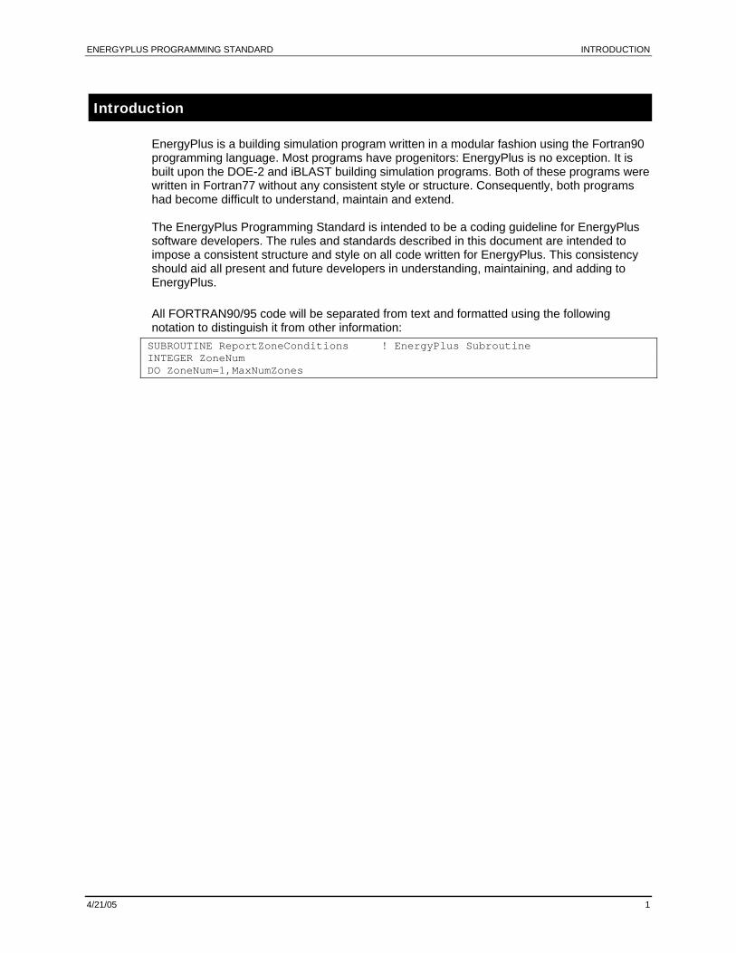
EnergyPlus is a building simulation program written in a modular fashion using the Fortran90 programming language. Most programs have progenitors: EnergyPlus is no exception. It is built upon the DOE-2 and iBLAST building simulation programs. Both of these programs were written in Fortran77 without any consistent style or structure. Consequently, both programs had become difficult to understand, maintain and extend. The EnergyPlus Programming Standard is intended to be a coding guideline for EnergyPlus software developers. The rules and standards described in this document are intended to impose a consistent structure and style on all code written for EnergyPlus. This consistency should aid all present and future developers in understanding, maintaining, and adding to EnergyPlus. All FORTRAN90/95 code will be separated from text and formatted using the following notation to distinguish it from other information: SUBROUTINE ReportZoneConditions ! EnergyPlus Subroutine INTEGER ZoneNum DO ZoneNum=1,MaxNumZones
ENERGYPLUS PROGRAMMING STANDARD REFERENCE DOCUMENTS
4/21/05 2
Reference Documents
This document is one of a set of documents for the EnergyPlus developer. Other documents in the set are:
Guide for Interface Developers: Everything you need to know about EnergyPlus Input and Output (to develop a user-friendly interface)
The Interface Developer’s Guide will tell you all the information about using and developing IDD (Input Data Dictionary) statements, Input Data File (IDF) statements, EnergyPlus outputs, and essentials of running EnergyPlus.
Guide for Module Developers: Everything you need to know about EnergyPlus Calculational Development (but were hesitant to ask)
The Module Developer’s Guide will tell you further about useful modules built into the EnergyPlus code that will make getting items from the IDF for your simulation relatively easy.
Engineering Reference: The Reference to EnergyPlus Calculations (in case you want or need to know)
The Engineering documentation gives details of the theory, equations and, occasionally, code snippets behind the EnergyPlus features.
Input-Output Reference: The Encyclopedic Reference to EnergyPlus Input and Output
Extensive details of the inputs used and outputs produced with EnergyPlus.
Output Details and Examples: An In-Depth Guide to EnergyPlus Output and Example Files
Extensive details output files and (future) examples files distributed with EnergyPlus.
Auxiliary Programs: To Increase Your Efficiency at Using EnergyPlus
Guides for the Weather Converter program, Using Ground Heat Transfer in EnergyPlus, HVAC Templates, WinEPDraw, EP-Macro, VCompare, and Transition (Convert old IDFs to later release version IDFs). (and more)
Getting Started: Everything You Need to Know about Running EnergyPlus (and a start at building simulation)
A guide to running EnergyPlus and some of the auxiliary programs as well as an introduction to building simulation modeling for those who might be new to the field or new to the precepts of EnergyPlus.
ENERGYPLUS PROGRAMMING STANDARD CODING STANDARD
4/21/05 3
Coding Standard
FORTRAN90/95
Due to the use of previous versions of FORTRAN in both DOE-2 and (I)BLAST legacy code and because of its advanced modular structures, FORTRAN90/95 has been chosen as the language of choice for EnergyPlus. All of the guidelines presented in this section (“Coding Standard”) are based on the use of FORTRAN90/95 for all code in EnergyPlus. The information in this section is not intended to be a complete description of the FORTRAN90 programming language but rather a supplement to the ANSI Standard. For those not familiar with Fortran90, the following books have proved useful to the development team: Fortran 90 Programming, T.M.R. Ellis, Ivor R. Phillips, Thomas M. Lahey, Addison-
Wesley, 1994.
Upgrading to Fortran 90, Cooper Redwine, Springer Verlag, 1995.
Fortran 90/95 for Scientists and Engineers, Chapman, Steven, McGraw Hill, 1998.
However, there are many other Fortran 90/95 texts available. A useful book about software design is: Code Complete: A Practical Handbook of Software Construction, Steve C McConnell,
Microsoft Press, 1993.
FORTRAN90 Code
For the EnergyPlus project, three types of code that may coexist in any version of the program: Legacy Code
Reengineered Code
New Code While these types of code will coexist in the EnergyPlus source, different expectations on the relative “purity” of the code will be enforced. All legacy code that is included in EnergyPlus must be at least F90 strict. (Note that legacy code included from another source may need permission/granting clauses to be place in EnergyPlus – see the Module Developer’s Guide for more on this). Mildly reengineered code (near legacy) that has not undergone any algorithm changes (only inclusion in a module, renaming of variables, etc.) will be allowed as long as it conforms to the F90 strict test. Reengineered code that has been modified significantly and all new code will be required to conform to the F90/95 pure standard. All code should be placed in “free-format” as opposed to the fixed format used by F77 and other versions of FORTRAN. (Legacy code may be converted from fixed to free format using a utility available from team members.) In addition, the following guidelines should be followed for all free-formatted code in EnergyPlus: Only ! is valid for indicating comments.
In-line comments are allowed and encouraged. Guidelines from Code Complete should be followed for inline comments. Several suggestions are repeated here:
Avoid endline (inline) comments that merely repeat the code.
ENERGYPLUS PROGRAMMING STANDARD CODING STANDARD
4/21/05 4
Avoid endline comments for multiple lines of code. In other words, avoid using a comment at the end of one line that applies to several lines of code.
Use endline comments to annotate data declarations.
Use endline comments for maintenance notes (bug fixes, for example).
Use endline comments to mark ends of blocks.
No lines should extend past 130 characters. (Absolute limit is 132 characters!)
It is suggested for readability that most lines be confined to 80 characters. This allows most code to be seen on a standard size screen and be printed without resorting to micro-fonts or landscape mode.
Column 6 is not associated with a continuation line in free format. To continue one line onto the next line, place an ampersand (&) at the end of the line to be continued.
The main program should begin with a PROGRAM statement.
To help visually distinguish between F90 syntax and other code elements such as comments and names, F90 syntax should be in all capital letters while other elements should be mixed case.
Tab characters are not allowed in any source code file. If the file editor allows tab characters, be certain to set it up so that the tab characters are converted to spaces upon saving the file.
It is highly recommended that programmers not use generic loop counters such as i, j, k, etc. This simply adds to the complexity of the code. The source code will be much easier to read if programmers use logical names for loop counting such as SurfaceNum, SystemNum, IterationNum, etc.
Though the standard allows for multiple statements on a line, do not use these. E.g. a=0; b=0 instead use: a=0 b=0
Likewise initialization statements can have multiples on a line, do not use these.
E.g. Integer, Save :: Var1=0, Var2=0 Instead use Integer, Save :: Var1=0 ! should also have commenting on what var1 is Integer, Save :: Var2=0 ! Var2 definition
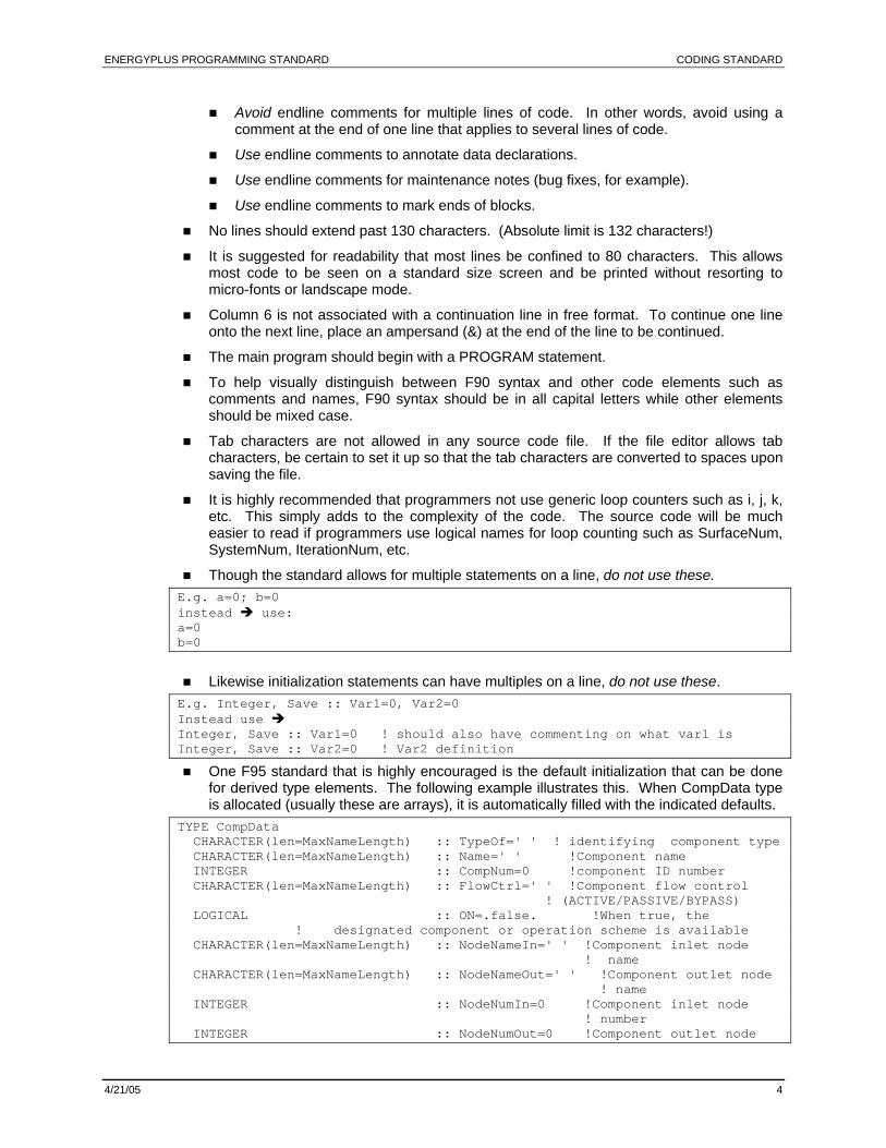
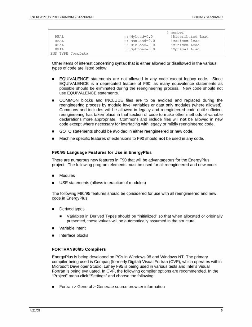
One F95 standard that is highly encouraged is the default initialization that can be done for derived type elements. The following example illustrates this. When CompData type is allocated (usually these are arrays), it is automatically filled with the indicated defaults.
TYPE CompData CHARACTER(len=MaxNameLength) :: TypeOf=' ' ! identifying component type CHARACTER(len=MaxNameLength) :: Name=' ' !Component name INTEGER :: CompNum=0 !component ID number CHARACTER(len=MaxNameLength) :: FlowCtrl=' ' !Component flow control ! (ACTIVE/PASSIVE/BYPASS) LOGICAL :: ON=.false. !When true, the ! designated component or operation scheme is available CHARACTER(len=MaxNameLength) :: NodeNameIn=' ' !Component inlet node ! name CHARACTER(len=MaxNameLength) :: NodeNameOut=' ' !Component outlet node ! name INTEGER :: NodeNumIn=0 !Component inlet node ! number INTEGER :: NodeNumOut=0 !Component outlet node
ENERGYPLUS PROGRAMMING STANDARD CODING STANDARD
4/21/05 5
! number REAL :: MyLoad=0.0 !Distributed Load REAL :: MaxLoad=0.0 !Maximum load REAL :: MinLoad=0.0 !Minimum Load REAL :: OptLoad=0.0 !Optimal Load END TYPE CompData
Other items of interest concerning syntax that is either allowed or disallowed in the various types of code are listed below: EQUIVALENCE statements are not allowed in any code except legacy code. Since
EQUIVALENCE is a deprecated feature of F90, as many equivalence statements as possible should be eliminated during the reengineering process. New code should not use EQUIVALENCE statements.
COMMON blocks and INCLUDE files are to be avoided and replaced during the reengineering process by module level variables or data only modules (where allowed). Commons and includes will be allowed in legacy and reengineered code until sufficient reengineering has taken place in that section of code to make other methods of variable declarations more appropriate. Commons and include files will not be allowed in new code except where necessary for interfacing with legacy or mildly reengineered code.
GOTO statements should be avoided in either reengineered or new code.
Machine specific features of extensions to F90 should not be used in any code.
F90/95 Language Features for Use in EnergyPlus
There are numerous new features in F90 that will be advantageous for the EnergyPlus project. The following program elements must be used for all reengineered and new code: Modules
USE statements (allows interaction of modules) The following F90/95 features should be considered for use with all reengineered and new code in EnergyPlus: Derived types
Variables in Derived Types should be “initialized” so that when allocated or originally presented, these values will be automatically assumed in the structure.
Variable intent
Interface blocks
FORTRAN90/95 Compilers
EnergyPlus is being developed on PCs in Windows 98 and Windows NT. The primary compiler being used is Compaq (formerly Digital) Visual Fortran (CVF), which operates within Microsoft Developer Studio. Lahey F95 is being used in various tests and Intel’s Visual Fortran is being evaluated. In CVF, the following compiler options are recommended. In the “Project” menu click “Settings” and choose the following: Fortran > General > Generate source browser information
ENERGYPLUS PROGRAMMING STANDARD CODING STANDARD
4/21/05 6
Fortran > Miscellaneous > Undeclared Symbols, Uninitialized Variables, Uncalled Routines
Fortran > Optimizations > None or Local optimizations
Fortran > Runtime > Array & String Bounds, Integer Overflow
Fortran > Runtime > Generate Traceback Information (DVF6 and above)
Fortran > Floating Point > Exception handling 0
Link > General > Generate Debug Info, Link incrementally
Link > Customize > Use program database
Link > Debug > Debug info
Browse Info > Build browse info file IT SHOULD ALSO BE NOTED THAT SINCE TAB CHARACTERS ARE NOT ALLOWED IN ENERGYPLUS BUT ARE VALID IN CVF THAT ALL DEVELOPERS SHOULD CONFIGURE IT TO REPLACE TABS WITH SPACES. THIS IS ACCOMPLISHED BY SELECTING THE OPTIONS ITEM IN THE TOOLS MENU. AFTER CLICKING ON THE TABS HEADING, CLICK ON INSERT SPACES FOR ALL THREE FILE TYPES. NOTE THAT THIS WILL INSERT SPACES INTO THE FILE EVERY TIME YOU PRESS THE TAB KEY AFTER YOU HAVE SET THIS OPTION. IT WILL NOT CONVERT ALREADY EXISTING TAB CHARACTERS IN THE FILE INTO SPACES. THAT MUST BE DONE MANUALLY OR WITH THE HELP OF A TEXT EDITOR.
Beyond F90/95 Language Features for Use in EnergyPlus
The original programming standard was written before F95 had been adopted. Though we don’t yet (2005) have fully compliant compilers for F2000+, we should begin using some of these features. Notably:
Allocatable structures in Derived Types -- if one has a variable length array that belongs to part of a Derived Type structure, F90 “allowed” these to be pointers. This is not, in general, a stellar idea and since F2000 allows these to be “allocatable”, EnergyPlus code should reflect that convention.
Naming Conventions
The naming conventions listed in the next several sections apply to reengineered and new code. Legacy code that is brought over “as is” will not be required to undergo name changes immediately. However, since it is anticipated that new and reengineered sections of code will affect most remaining sections of legacy code, the renaming of variables in legacy code will be necessary at some point. Thus, name changes that occur in legacy code should follow these conventions even if they are not accompanied by any algorithm modifications. In all of the naming conventions listed below, it is implicitly assumed that the limit on the length of names is 31 characters and that spaces are not allowed as valid characters in any of the names. Also, underscores (“_”) should be avoided.
Subroutine Naming Convention
Subroutine names should be constructed using the verb-predicate rule. Every subroutine models an action on some item. Thus, the subroutine name should reflect this by including both the action and the item upon which the action is taken. The verb should be the first part of the name followed by the predicate. Below are some examples of the verb-predicate notation: CorrectZoneAirTemp
CalcZoneMassBalance
ENERGYPLUS PROGRAMMING STANDARD CODING STANDARD
4/21/05 7
SimAirLoops
ReportFan Notice that the first letter of each word is capitalized to make the name easier to read. In general, the use of longer names for subroutine names rather than abbreviations is encouraged because subroutine names will not appear often in the code. However, abbreviations may be used if the subroutine name will be longer than the 31-character limit.
Module and Source Code File Naming Convention
Since modules typically are associated with objects or data groupings, the name which is selected for a module should refer to the object or data grouping. For example, a module that deals with pumps in the central plant should be called “PlantPumps”. Modules which consist of only variable declarations (data-only module, see section on Variable Declarations) should use a “Data” prefix for its name followed by a logical descriptive term or terms. An example of a potential name for a data-only module is “DataGlobals”. Since each file containing source code will consist of a single program module, source code files should use the name of the module as the base name and a “.f90” as the file extension. Thus, the examples listed in the preceding paragraph would be contained in the files PlantPumps.f90 and DataGlobals.f90. It should be noted that there are some limits on file names on certain machines. Consequently, it may be desirable to omit terms such as “algorithm” or “model” from module names.
Variable Naming Convention
While 31 characters are the absolute limit on the length of variable names, programmers should note that variable names tend to appear in the code much more often than subroutine or module names. As a result, the use of extremely long variable names can become burdensome for the programmer to enter and make the code more difficult to read since it may cause program statements to be strung out over several lines. On the other hand, the use of short, cryptic names makes it difficult to understand the code without extensive documentation. For variable names, logical abbreviations are thus encouraged. Typically, lengthy words should be shortened to somewhere between three and five characters to make a logical yet concise name for the various program variables. For example, the variable for the humidity ratio of the air entering the cooling coil might be named “InletAirHumRat”. In addition, plurals should not be used (i.e., use Zone instead of Zones, System instead of Systems, etc.) in variable names. A list of approved abbreviations for use in EnergyPlus programming may be found in Appendix A. In some cases, words have not been abbreviated because they are five letters long or shorter or a logical abbreviation could not be determined. As with all of the other items found in this standard, developers should use their judgement on the implementation of these abbreviations within programming code. When in doubt, it might be best not to use an abbreviation in some cases. It should be noted that an explicit order for items, modifiers, etc. cannot be defined using the verb-predicate rule for the subroutine names. This, in part, is because some variables are complicated with more than one noun (InletAirHumRat) or might have several modifiers (NumSingleTempHeatCoolControls). One suggestion on the order that the abbreviations might occur in the name is to give preference to the more important or higher level elements. As always, the developer should use common sense in applying these guidelines to program code.
ENERGYPLUS PROGRAMMING STANDARD CODING STANDARD
4/21/05 8
Program Variables
Variable Declarations and Usage
One of the guiding philosophies for the variable handling in EnergyPlus is that variables are only available and accessible where they are needed. This is one of the benefits of modules, i.e., that information which is not needed by a particular routine can be hidden from it. Limiting the scope of variables also makes the code easier to read, maintain, and test. Another goal of this standard is to minimize the amount of information that must be transferred from one routine to another via a passed variable list and to eliminate the need for commons. In order to ensure that this goal is realized, several restrictions on the availability of variables must be observed. It should be noted that all EnergyPlus subroutines and functions declare “IMPLICIT NONE” near the beginning of each routine or function. Consequently, all variables must be declared using valid F90 syntax. In F90, programmer has the ability to define certain variables as either private or public. This specification has implications on the availability of a particular variable outside of that module. Only four methods of variable definition should be allowed in EnergyPlus: 1) Subroutine Level Variables. The first method of defining a variable is at the subroutine
level as private. This definition is consistent with the F77 local variable. Subroutine level variables are not available anywhere outside the subroutine in which they are declared. Thus, by definition, any variable declared at the subroutine level is “private”. Local subroutine variables should be the first choice for the method of declaration.
2) Module Level Variables — Private. An alternative for defining a variable is private at the module level. Variables defined in this way are available to all of the subroutines in the module but to no routines outside the module or other modules. This definition is closely related to the use of common blocks in F77 code except that related data has now been grouped into a particular section of the code. Declaring a variable as private at the module level avoids the need to pass the variable from one subroutine to another within the same module. It should be noted, however, that it is inadvisable to declare loop counters or any other variable that could be declared as a subroutine local variable as module level variables. While it may seem redundant to declare a variable in several subroutines, experience has shown that such an abuse of module level variables is poor programming and will inevitably lead to program bugs.
3) Data Only Module — Public (Superblock). In most cases, the prudent selection of module routines will result in the need for only subroutine level and private module-level variables. However, there will be some circumstances involving either legacy code or complex new code where the variables will need to be accessible in several related modules. Such related modules are considered a superblock. Variables that are used in several related modules should be separated and defined in a module that only includes public variable declarations. Defining module level variables as “public” should only be done when variables must be shared in a significant number of modules in a superblock. For example, material properties are used in several parts of the heat balance code that may be broken up into separate modules. Elevating variables to public status in data only modules should be a rare exception to the previous two rules and should be done with caution. Variables declared as public should only be used within modules that are considered part of their superblock (e.g., waste heat should not be used in the heat balance). Note that variables in modules that have subroutines should not be defined as public.
4) Data Only Module — Public (Global). As in almost any other significant program, EnergyPlus will have certain variables that will be utilized in every module in the code.
ENERGYPLUS PROGRAMMING STANDARD CODING STANDARD
4/21/05 9
When several superblocks require access to a variable, it must be elevated to “global” status. As a rule, there should be very few global variables, and elevating a variable to global status should only be used as a last resort. Variables which may end up being global variables include: physical and geometric constants such as π, environment information variables (described in a later section) such as time, date, hour, time step, etc., and file unit numbers.
Another issue related to variable declaration that has been addressed by this standard is the static vs. dynamic storage of local subroutine variables. Due to the large number of legacy code variables that may become part of the EnergyPlus program, it was necessary to specify the static storage of variables as a compiler flag. Variables in new and reengineered code should take advantage of dynamic allocation when possible and be explicit about its need to save variable values between subroutine calls. Two features of F90/95 that this standard encourages the use of but does not mandate are intent and derived types. Intent allows the programmer to declare how a passed variable will be used within a subroutine: as in input, an output, or both. The use of intent is another issue of the clarity of variable usage. With the intent of a variable explicitly defined, bugs in the program will show up much earlier in the development process and will be easier to detect and eliminate. Derived types offer a convenient way to group and, if necessary, pass related variables. They are a method for constructing custom data structures within a program. For example, all of the information about a cooling coil could be defined as derived type. Consult any F90 book on the merit, advantages, and applications of derived types. While derived types can be nested (one derived type becomes part of another, etc.), no derived type used with EnergyPlus should be nested more than three layers deep. One feature of F77 that will be eliminated during the process of reengineering the legacy code is the use of common blocks (and the include files which contain them). While common blocks are allowed in legacy code, their use in reengineered and new code will be limited to any temporary scaffolding that is needed to mesh between the old data system and the improved structure as outlined in this document. Even with that, they should only be used until the developer is comfortable that the new/revised structure is performing as the old and then the common blocks should be removed. Ideally, this will happen prior to its being included in a version of official EnergyPlus code.
Units in EnergyPlus
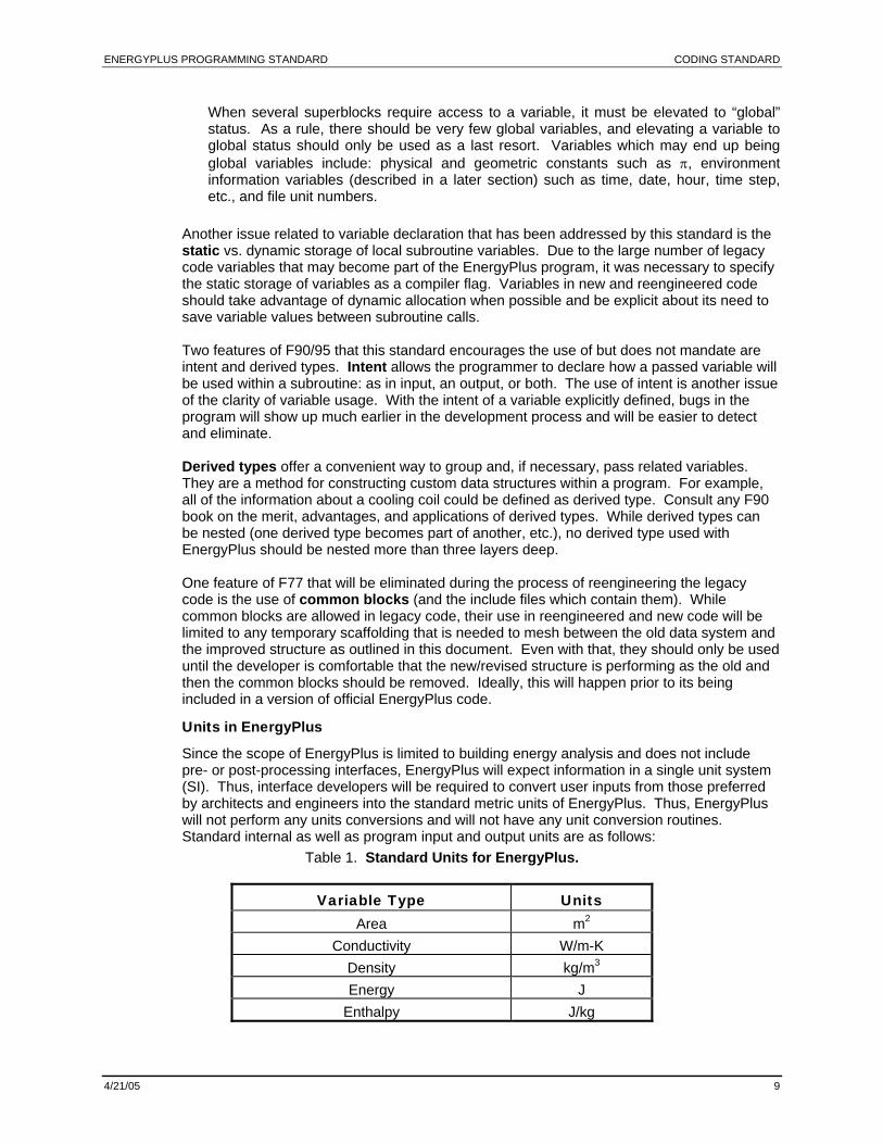
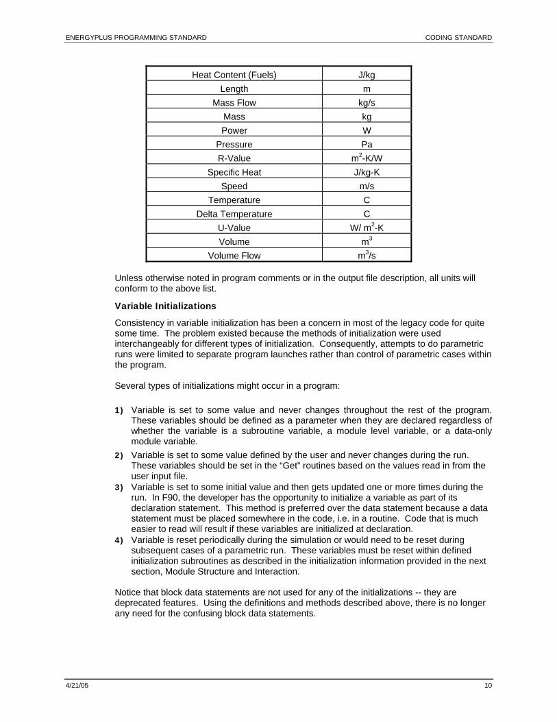
Since the scope of EnergyPlus is limited to building energy analysis and does not include pre- or post-processing interfaces, EnergyPlus will expect information in a single unit system (SI). Thus, interface developers will be required to convert user inputs from those preferred by architects and engineers into the standard metric units of EnergyPlus. Thus, EnergyPlus will not perform any units conversions and will not have any unit conversion routines. Standard internal as well as program input and output units are as follows:
Table 1. Standard Units for EnergyPlus.
Variable Type Units Area m2
Conductivity W/m-K Density kg/m3 Energy J
Enthalpy J/kg
ENERGYPLUS PROGRAMMING STANDARD CODING STANDARD
4/21/05 10
Heat Content (Fuels) J/kg Length m
Mass Flow kg/s Mass kg Power W
Pressure Pa R-Value m2-K/W
Specific Heat J/kg-K Speed m/s
Temperature C Delta Temperature C
U-Value W/ m2-K Volume m3
Volume Flow m3/s Unless otherwise noted in program comments or in the output file description, all units will conform to the above list.
Variable Initializations
Consistency in variable initialization has been a concern in most of the legacy code for quite some time. The problem existed because the methods of initialization were used interchangeably for different types of initialization. Consequently, attempts to do parametric runs were limited to separate program launches rather than control of parametric cases within the program. Several types of initializations might occur in a program: 1) Variable is set to some value and never changes throughout the rest of the program.
These variables should be defined as a parameter when they are declared regardless of whether the variable is a subroutine variable, a module level variable, or a data-only module variable.
2) Variable is set to some value defined by the user and never changes during the run. These variables should be set in the “Get” routines based on the values read in from the user input file.
3) Variable is set to some initial value and then gets updated one or more times during the run. In F90, the developer has the opportunity to initialize a variable as part of its declaration statement. This method is preferred over the data statement because a data statement must be placed somewhere in the code, i.e. in a routine. Code that is much easier to read will result if these variables are initialized at declaration.
4) Variable is reset periodically during the simulation or would need to be reset during subsequent cases of a parametric run. These variables must be reset within defined initialization subroutines as described in the initialization information provided in the next section, Module Structure and Interaction.
Notice that block data statements are not used for any of the initializations -- they are deprecated features. Using the definitions and methods described above, there is no longer any need for the confusing block data statements.
ENERGYPLUS PROGRAMMING STANDARD CODING STANDARD
4/21/05 11
Unused Variables
Unused variables can usually be flagged by compilers. While some unused variables might be intended for later/future developments, these should be commented out until such time as their use is needed.
Module Structure and Interaction
Module Usage in EnergyPlus
The module is the building block of the EnergyPlus program code. Modules are many times used to bring together either related algorithms or related data. In EnergyPlus, modules are used for grouping both data and algorithms because in many cases they are linked together. The EnergyPlus Module Structure has four important goals:
to promote uniformity of program code
to simplify the process of adding additional modules to the code
to enhance the testing capability of various program elements
to replace the extremely confusing data structure with a more understandable, segmented data structure as defined in the previous section.
Modules appear to be most consistently organized when a map of the various modules and their interaction form an inverted tree or pyramid shape. EnergyPlus uses a modified form of this tree structure in that one main driver module accesses the heat balance module. In turn, the heat balance module interacts with the main system module through the heat balance-system “interface”. In a like manner, the major blocks of the HVAC code also interact through defined “interfaces”. Each of these main program elements access routines and data contained in other related modules. The transformation of the code from a distributed program environment into discrete modules requires careful planning. The next several sections outline the potential elements of each module. This information should serve as a guide to constructing a module either from new or legacy code. Again, programmers should remember to take both data structure and algorithmic considerations into account when constructing a module for EnergyPlus.
Driver Subroutines
Driver routines are subroutines contained within a module that are called from subroutines in other modules. Access to the module and its data elements are only allowed through the driver routines. These routines would be the only PUBLIC routines in the module (with the possible exception of some of the input routines) since they are accessed from outside of the module. All other routines in this module are accessed from these main driver routines. The main driver subroutines may contain any programming necessary to model the component or element on a macroscopic level. Other details of the algorithm should be contained in one of the subroutine types described below. Therefore, the driver routines will in most cases be a list of subroutine calls and possibly some control logic. For convenience, the programmer may specify a sub-driver routine for each of the main subroutine sections described below to minimize the number of calls that appear in the main driver routine.
Environment Flags
One set of variables that are candidates for elevation to “GLOBAL” status is the environment flags. The environment flags serve to keep track of time during the simulation. There are environment variables for hour, time step, sub-time step, day, etc. In addition, there are flags which are set to tell whether the current moment in the simulation is the beginning of a
ENERGYPLUS PROGRAMMING STANDARD CODING STANDARD
4/21/05 12
particular time frame (time step, hour, day, etc.) or at the end of the time frame. This information is extremely important to the driver subroutine that controls the simulation of the component module. Based on the values of the environment flags, the driver will decide what types of initializations are required, whether input data must be read, the record keeping that must be done, and if reporting is necessary. In other words, the environment variables help the driver control all of the actions taken on the local and module variables except actual changes required by the model algorithms.
User Data Interface Subroutines (Get routines)
Most, if not all, modules require some input from the user such as design values, locations, schedules, etc. Consequently, these modules must have subroutines that interface with the user data. These routines are called from the driver routine(s) of this module or possibly from an input reading driver routine. It is also conceivable that this section might include some standard file operations such as “new”, “open”, “save”, “save as”, etc. that would relate to the external storage of input data for this module. In short, these routines are responsible only for transferring information from the user-input file to the particular variables.
Initialization Subroutine(s)
All routines that perform any required manipulations on the user data to obtain simulation ready information are considered initialization subroutines. The routines in this section may include several routines that are called from the driver subroutines within this module based on the value of the global environment (status) flags. For example, at the beginning of the simulation, one subroutine may be called to set up information that will be valid throughout the simulation such as processing of coil design data into a simulation-ready format. There may also be monthly, daily, hour, and time step level initializations that must be performed. Each of these levels could have a separate subroutine in this section dedicated to such initializations. Generally, though, it is preferred that all initializations be performed in one “Init” routine.
Calculation Routines and Utility Subroutines and Functions
This section includes any calculations that are required to simulate the element represented by this module. Thus, most of the details of the algorithm will be contained in this section. There should be one “Calc” routine and as many utility routines as are needed. Generally, no data movement will take place in the calculation section of the module.
Update Routine(s)
This section normally consists of one routine that performs any data transfer or movement that is needed within EnergyPlus, after the actual calculation in the module has taken place.
Reporting Subroutine(s)
Usually there is one reporting routine for each module. This routine will do any calculation that is needed strictly for output or reporting purposes and will contain the calls to the EnergyPlus reporting routines.
USE Statements in EnergyPlus
Once the various modules have been constructed, the “blocks” of the “pyramid” must be assembled using the F90 “USE” statements. The USE statement allows access from one module to another. For example, in EnergyPlus, since the ManageSimulation subroutine calls the ManageHeatBalance subroutine, it must have access to the HeatBalanceModule. Thus, the ManageSimulation subroutine or the SimulationManager module must have a USE
ENERGYPLUS PROGRAMMING STANDARD CODING STANDARD
4/21/05 13
HeatBalanceModule statement in it to allow this access. The USE statement also allows access to the data-only modules. One question that arises through the implementation of USE statements is: “Where does the USE statement belong—at the module level or the subroutine level?” At this point, a definite rule has not been established to answer this question. However, the following guidelines seem reasonable and appropriate to the goals of this programming standard: USE statements that are required for access to a subroutine that is in another module
probably belong at the subroutine level. In the example above, if the call to ManageHeatBalance is the only access to HeatBalanceModule from within the SimulationManager module, then the USE statement should probably reside at the subroutine level (in subroutine ManageSimulation in this case).
If there are numerous calls from various subroutines in one module to another module, then the programmer may wish to elevate the USE statement to the module level for the sake of convenience. The number of calls threshold is left to the discretion of the programmer.
Due to the definition of “global” data (i.e., global data should be available everywhere), any USE statements which are included for access to the global data (DataGlobals) must be placed at the module level.
USE statements for access to “super-block” data-only modules can be placed at either the subroutine or the module level though it is recommended that these USE statements reside at the module level. If data is only used in a single subroutine, the programmer may need to consider passing the data as subroutine arguments.
Example of the EnergyPlus Module Structure
The code listed in the Module Developer’s Guide is intended to give the reader a good example of how to implement the module described in the previous sections.
Generic Subroutines and Functions
There is a good possibility that the EnergyPlus code may contain some “generic” mathematical functions or procedures that are used by several, disparate sections of the program. Rather than repeat this code in each module that it is required, it might be appropriate to construct a generic subroutine/function module. Then, subroutines that need that function can use this generic module. Some examples of processes that might be included in a generic procedure module include array-zeroing subroutines, special functions not included in the F90 standard, etc. Developers should note that F90 does include a variety of matrix manipulation intrinsic functions. These standard functions should be used unless there are special conditions that require more specific programming. Subroutines or functions that are only called from a single module should be included in the utilities section of that module. Finally, subroutines or functions added to this generic process module should be written in the most general terms so that any routine which must call into this module will be able to do this without the assistance of extra programming or the definition of a new routine. Several routines, such as “GetNumObject” or other “Get” routines as well as Psychrometric functions have already been defined for the EnergyPlus Developer. To find out more about these, refer to the Module Developer’s Guide.
ENERGYPLUS PROGRAMMING STANDARD CODING STANDARD
4/21/05 14
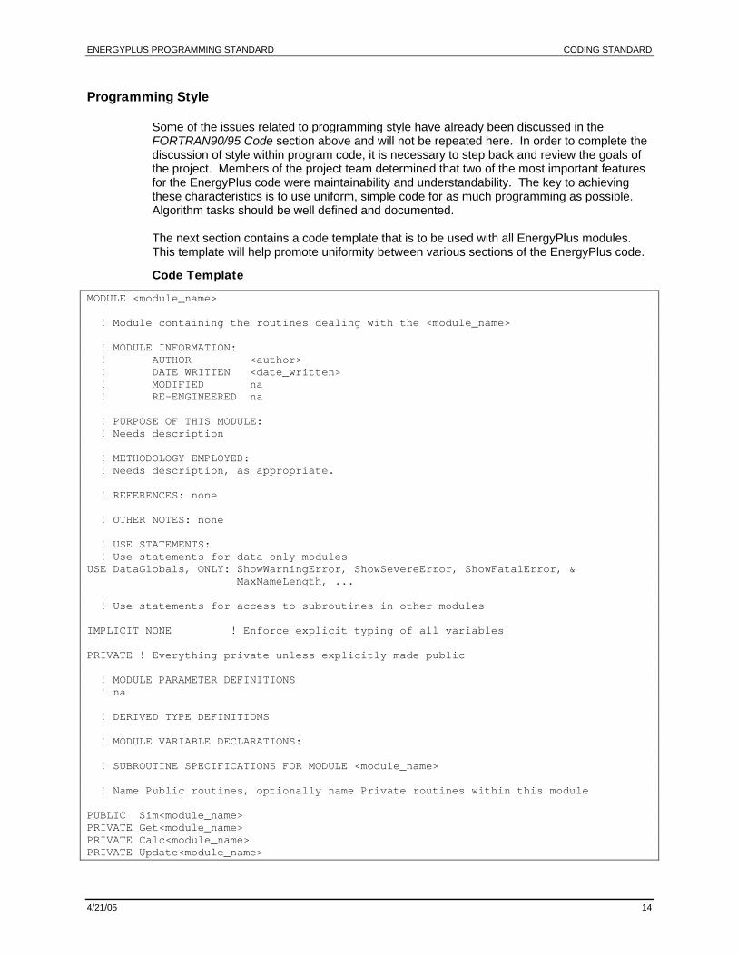
Programming Style
Some of the issues related to programming style have already been discussed in the FORTRAN90/95 Code section above and will not be repeated here. In order to complete the discussion of style within program code, it is necessary to step back and review the goals of the project. Members of the project team determined that two of the most important features for the EnergyPlus code were maintainability and understandability. The key to achieving these characteristics is to use uniform, simple code for as much programming as possible. Algorithm tasks should be well defined and documented. The next section contains a code template that is to be used with all EnergyPlus modules. This template will help promote uniformity between various sections of the EnergyPlus code.
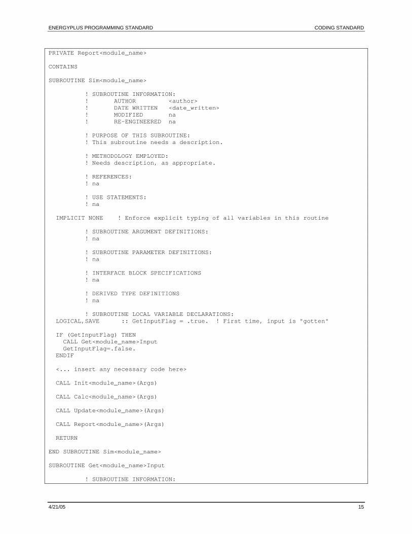
Code Template
MODULE <module_name> ! Module containing the routines dealing with the <module_name> ! MODULE INFORMATION: ! AUTHOR <author> ! DATE WRITTEN <date_written> ! MODIFIED na ! RE-ENGINEERED na ! PURPOSE OF THIS MODULE: ! Needs description ! METHODOLOGY EMPLOYED: ! Needs description, as appropriate. ! REFERENCES: none ! OTHER NOTES: none ! USE STATEMENTS: ! Use statements for data only modules USE DataGlobals, ONLY: ShowWarningError, ShowSevereError, ShowFatalError, & MaxNameLength, ... ! Use statements for access to subroutines in other modules IMPLICIT NONE ! Enforce explicit typing of all variables PRIVATE ! Everything private unless explicitly made public ! MODULE PARAMETER DEFINITIONS ! na ! DERIVED TYPE DEFINITIONS ! MODULE VARIABLE DECLARATIONS: ! SUBROUTINE SPECIFICATIONS FOR MODULE <module_name> ! Name Public routines, optionally name Private routines within this module PUBLIC Sim<module_name> PRIVATE Get<module_name> PRIVATE Calc<module_name> PRIVATE Update<module_name>
ENERGYPLUS PROGRAMMING STANDARD CODING STANDARD
4/21/05 15
PRIVATE Report<module_name> CONTAINS SUBROUTINE Sim<module_name> ! SUBROUTINE INFORMATION: ! AUTHOR <author> ! DATE WRITTEN <date_written> ! MODIFIED na ! RE-ENGINEERED na ! PURPOSE OF THIS SUBROUTINE: ! This subroutine needs a description. ! METHODOLOGY EMPLOYED: ! Needs description, as appropriate. ! REFERENCES: ! na ! USE STATEMENTS: ! na IMPLICIT NONE ! Enforce explicit typing of all variables in this routine ! SUBROUTINE ARGUMENT DEFINITIONS: ! na ! SUBROUTINE PARAMETER DEFINITIONS: ! na ! INTERFACE BLOCK SPECIFICATIONS ! na ! DERIVED TYPE DEFINITIONS ! na ! SUBROUTINE LOCAL VARIABLE DECLARATIONS: LOGICAL,SAVE :: GetInputFlag = .true. ! First time, input is "gotten" IF (GetInputFlag) THEN CALL Get<module_name>Input GetInputFlag=.false. ENDIF <... insert any necessary code here> CALL Init<module_name>(Args) CALL Calc<module_name>(Args) CALL Update<module_name>(Args) CALL Report<module_name>(Args) RETURN END SUBROUTINE Sim<module_name> SUBROUTINE Get<module_name>Input ! SUBROUTINE INFORMATION:
ENERGYPLUS PROGRAMMING STANDARD CODING STANDARD
4/21/05 16
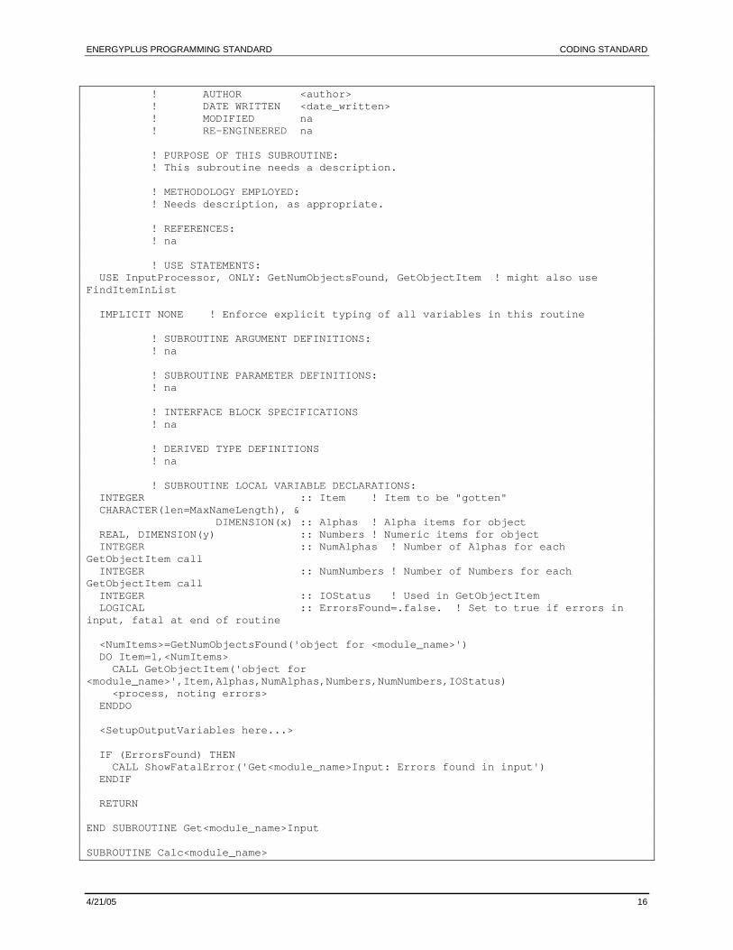
! AUTHOR <author> ! DATE WRITTEN <date_written> ! MODIFIED na ! RE-ENGINEERED na ! PURPOSE OF THIS SUBROUTINE: ! This subroutine needs a description. ! METHODOLOGY EMPLOYED: ! Needs description, as appropriate. ! REFERENCES: ! na ! USE STATEMENTS: USE InputProcessor, ONLY: GetNumObjectsFound, GetObjectItem ! might also use FindItemInList IMPLICIT NONE ! Enforce explicit typing of all variables in this routine ! SUBROUTINE ARGUMENT DEFINITIONS: ! na ! SUBROUTINE PARAMETER DEFINITIONS: ! na ! INTERFACE BLOCK SPECIFICATIONS ! na ! DERIVED TYPE DEFINITIONS ! na ! SUBROUTINE LOCAL VARIABLE DECLARATIONS: INTEGER :: Item ! Item to be "gotten" CHARACTER(len=MaxNameLength), & DIMENSION(x) :: Alphas ! Alpha items for object REAL, DIMENSION(y) :: Numbers ! Numeric items for object INTEGER :: NumAlphas ! Number of Alphas for each GetObjectItem call INTEGER :: NumNumbers ! Number of Numbers for each GetObjectItem call INTEGER :: IOStatus ! Used in GetObjectItem LOGICAL :: ErrorsFound=.false. ! Set to true if errors in input, fatal at end of routine <NumItems>=GetNumObjectsFound('object for <module_name>') DO Item=1,<NumItems> CALL GetObjectItem('object for <module_name>',Item,Alphas,NumAlphas,Numbers,NumNumbers,IOStatus) <process, noting errors> ENDDO <SetupOutputVariables here...> IF (ErrorsFound) THEN CALL ShowFatalError('Get<module_name>Input: Errors found in input') ENDIF RETURN END SUBROUTINE Get<module_name>Input SUBROUTINE Calc<module_name>
ENERGYPLUS PROGRAMMING STANDARD CODING STANDARD
4/21/05 17
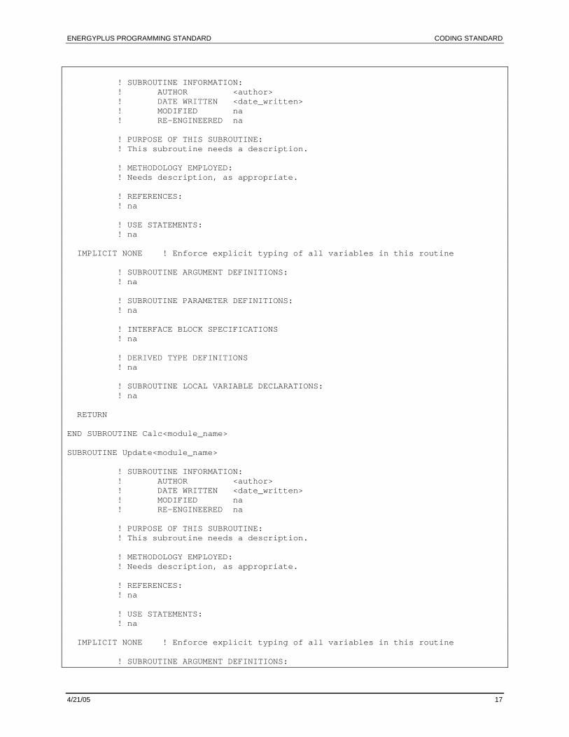
! SUBROUTINE INFORMATION: ! AUTHOR <author> ! DATE WRITTEN <date_written> ! MODIFIED na ! RE-ENGINEERED na ! PURPOSE OF THIS SUBROUTINE: ! This subroutine needs a description. ! METHODOLOGY EMPLOYED: ! Needs description, as appropriate. ! REFERENCES: ! na ! USE STATEMENTS: ! na IMPLICIT NONE ! Enforce explicit typing of all variables in this routine ! SUBROUTINE ARGUMENT DEFINITIONS: ! na ! SUBROUTINE PARAMETER DEFINITIONS: ! na ! INTERFACE BLOCK SPECIFICATIONS ! na ! DERIVED TYPE DEFINITIONS ! na ! SUBROUTINE LOCAL VARIABLE DECLARATIONS: ! na RETURN END SUBROUTINE Calc<module_name> SUBROUTINE Update<module_name> ! SUBROUTINE INFORMATION: ! AUTHOR <author> ! DATE WRITTEN <date_written> ! MODIFIED na ! RE-ENGINEERED na ! PURPOSE OF THIS SUBROUTINE: ! This subroutine needs a description. ! METHODOLOGY EMPLOYED: ! Needs description, as appropriate. ! REFERENCES: ! na ! USE STATEMENTS: ! na IMPLICIT NONE ! Enforce explicit typing of all variables in this routine ! SUBROUTINE ARGUMENT DEFINITIONS:
ENERGYPLUS PROGRAMMING STANDARD CODING STANDARD
4/21/05 18
! na ! SUBROUTINE PARAMETER DEFINITIONS: ! na ! INTERFACE BLOCK SPECIFICATIONS ! na ! DERIVED TYPE DEFINITIONS ! na ! SUBROUTINE LOCAL VARIABLE DECLARATIONS: ! na RETURN END SUBROUTINE Update<module_name> SUBROUTINE Report<module_name> ! SUBROUTINE INFORMATION: ! AUTHOR <author> ! DATE WRITTEN <date_written> ! MODIFIED na ! RE-ENGINEERED na ! PURPOSE OF THIS SUBROUTINE: ! This subroutine needs a description. ! METHODOLOGY EMPLOYED: ! Needs description, as appropriate. ! REFERENCES: ! na ! USE STATEMENTS: ! na IMPLICIT NONE ! Enforce explicit typing of all variables in this routine ! SUBROUTINE ARGUMENT DEFINITIONS: ! na ! SUBROUTINE PARAMETER DEFINITIONS: ! na ! INTERFACE BLOCK SPECIFICATIONS ! na ! DERIVED TYPE DEFINITIONS ! na ! SUBROUTINE LOCAL VARIABLE DECLARATIONS: ! na < this routine is typically needed only for those cases where you must transform the internal data to a reportable form> RETURN END SUBROUTINE Report<module_name> END MODULE <module_name>
ENERGYPLUS PROGRAMMING STANDARD CODING STANDARD
4/21/05 19
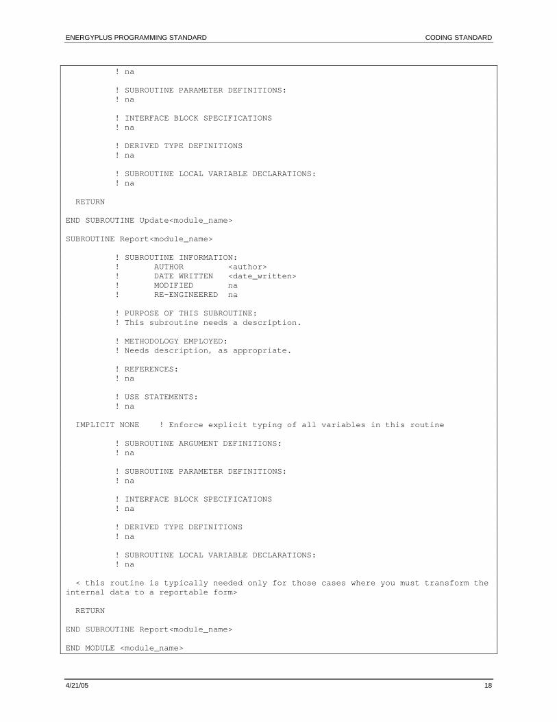
Notes on the EnergyPlus Code Template
Programmers should copy the above text into an empty file, changing names and filling in comments and code as appropriate. Comments in the template that are enclosed in {{double braces}} should be replaced with actual comments specific to the module or subroutine. Comments that are enclosed in <<double hinges>> should be replaced with program code. Other comments should be left in the file as they are. Note that some of the comments appear in all capital letters while others appear in mixed case. These all capitalized comments are special “header” comments. Developer comments should be in sentence case rather than all upper case. All comments (including in-line comments) should begin in the 11th column or later to help set them off visually from the code. In-line comments should leave at least one blank character between the end of the syntax and the comment marker. Furthermore, it should be noted that the indentation of program code did not begin until the subroutine level had been reached. Finally, functions may be added in a similar manner as the subroutines.
Good Coding Practices
Though we hope that the interfaces to EnergyPlus will produce correct input files, this may not be the case. Therefore, you should program defensively when accepted incorrect data will cause your routines to go “belly-up”. For example, the “ShowFatalError” routine is called in the code example (Ref: Module Developer’s Guide) when the “SimulateFanComponents” is passed a fan name that it cannot find in the list of fans. Ideally, this kind of error-checking should be accomplished during the “Get” routines for the module. Nevertheless, having this detection somewhere (anywhere) will save countless hours of debugging an incorrect input file.
Code Readability vs. Speed of Execution
Programmers throughout time have had to deal with speed of code execution and it’s an ongoing concern. However, compilers are pretty smart these days and, often, can produce speedier code for the hardware platform than the programmer can when he or she uses “speed up” tips. The EnergyPlus development team would rather the code be more “readable” to all than to try to outwit the compilers for every platform. First and foremost, the code is the true document of what EnergyPlus does – other documents will try to explain algorithms and such but must really take a back seat to the code itself.
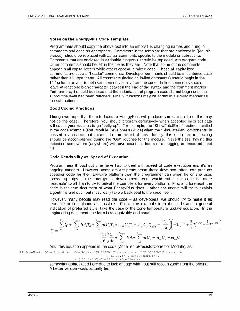
However, many people may read the code – as developers, we should try to make it as readable at first glance as possible. For a true example from the code and a general indication of preferred style, take the case of the zone temperature update equation. In the engineering document, the form is recognizable and usual:
2 3inf supply
1 1 1
inf1 1
3 13
2 3116
surfacessl zones
surfaces zones
NN Nt t t t t tz
i i i si i p zi p sys p z z zt i i i
z N Nz
i i p p sysi i
CQ h AT m C T m C T m C T T T T
tTC
h A m C m C m Ct
δ δ δ
δ
δ
− − −∞
= = =
= =
+ + + + − − + −=
+ + + +
⎛ ⎞⎛ ⎞⎜ ⎟⎜ ⎟⎝ ⎠⎝ ⎠
⎛ ⎞⎜ ⎟⎝ ⎠
∑ ∑ ∑
∑ ∑And, this equation appears in the code (ZoneTempPredictorCorrector Module), as:
ZT(ZoneNum)= (CoefSumhat + CoefAirrat*(3.0*ZTM1(ZoneNum) - (3.0/2.0)*ZTM2(ZoneNum) & + (1./3.)* ZTM3(ZoneNum))) & / ((11.0/6.0)*CoefAirrat+CoefSumha)
somewhat abbreviated here due to lack of page width but still recognizable from the original. A better version would actually be:
ENERGYPLUS PROGRAMMING STANDARD CODING STANDARD
4/21/05 20
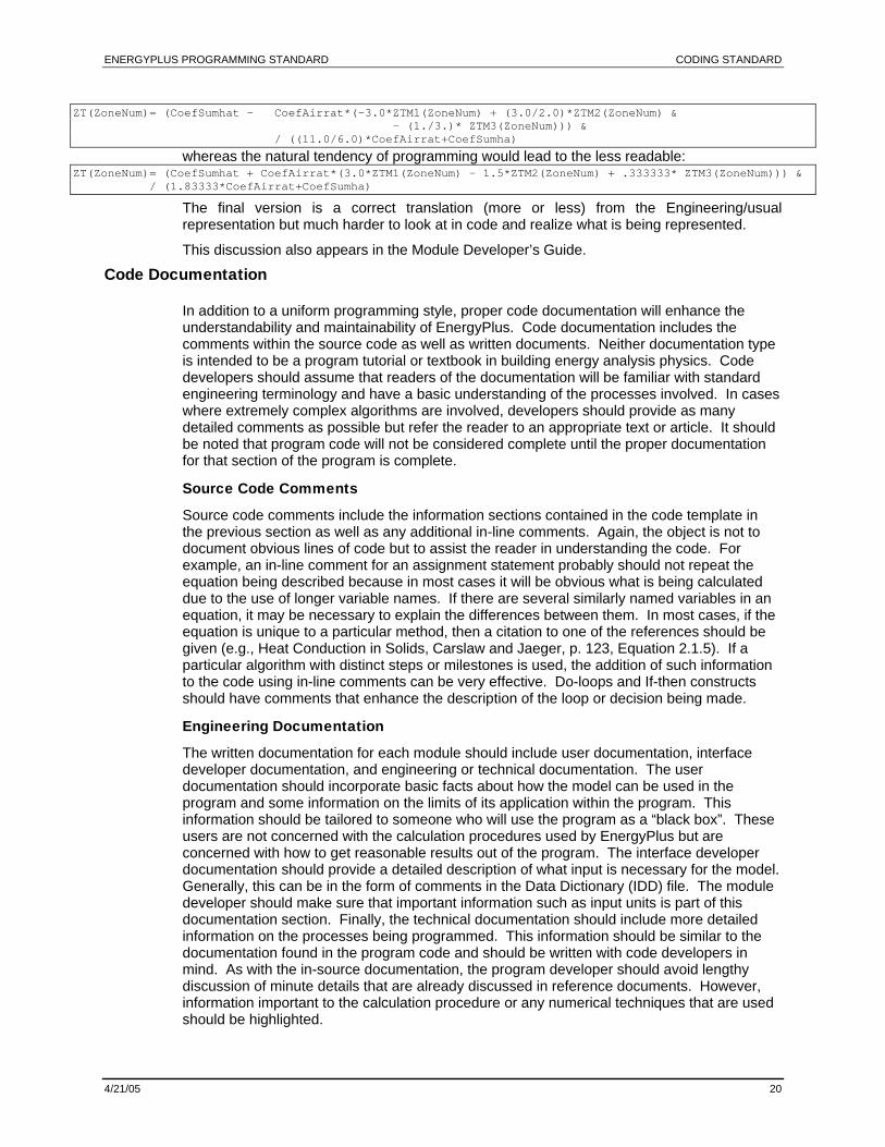
ZT(ZoneNum)= (CoefSumhat - CoefAirrat*(-3.0*ZTM1(ZoneNum) + (3.0/2.0)*ZTM2(ZoneNum) & - (1./3.)* ZTM3(ZoneNum))) & / ((11.0/6.0)*CoefAirrat+CoefSumha)
whereas the natural tendency of programming would lead to the less readable: ZT(ZoneNum)= (CoefSumhat + CoefAirrat*(3.0*ZTM1(ZoneNum) – 1.5*ZTM2(ZoneNum) + .333333* ZTM3(ZoneNum))) & / (1.83333*CoefAirrat+CoefSumha)
The final version is a correct translation (more or less) from the Engineering/usual representation but much harder to look at in code and realize what is being represented.
This discussion also appears in the Module Developer’s Guide.
Code Documentation
In addition to a uniform programming style, proper code documentation will enhance the understandability and maintainability of EnergyPlus. Code documentation includes the comments within the source code as well as written documents. Neither documentation type is intended to be a program tutorial or textbook in building energy analysis physics. Code developers should assume that readers of the documentation will be familiar with standard engineering terminology and have a basic understanding of the processes involved. In cases where extremely complex algorithms are involved, developers should provide as many detailed comments as possible but refer the reader to an appropriate text or article. It should be noted that program code will not be considered complete until the proper documentation for that section of the program is complete.
Source Code Comments
Source code comments include the information sections contained in the code template in the previous section as well as any additional in-line comments. Again, the object is not to document obvious lines of code but to assist the reader in understanding the code. For example, an in-line comment for an assignment statement probably should not repeat the equation being described because in most cases it will be obvious what is being calculated due to the use of longer variable names. If there are several similarly named variables in an equation, it may be necessary to explain the differences between them. In most cases, if the equation is unique to a particular method, then a citation to one of the references should be given (e.g., Heat Conduction in Solids, Carslaw and Jaeger, p. 123, Equation 2.1.5). If a particular algorithm with distinct steps or milestones is used, the addition of such information to the code using in-line comments can be very effective. Do-loops and If-then constructs should have comments that enhance the description of the loop or decision being made.
Engineering Documentation
The written documentation for each module should include user documentation, interface developer documentation, and engineering or technical documentation. The user documentation should incorporate basic facts about how the model can be used in the program and some information on the limits of its application within the program. This information should be tailored to someone who will use the program as a “black box”. These users are not concerned with the calculation procedures used by EnergyPlus but are concerned with how to get reasonable results out of the program. The interface developer documentation should provide a detailed description of what input is necessary for the model. Generally, this can be in the form of comments in the Data Dictionary (IDD) file. The module developer should make sure that important information such as input units is part of this documentation section. Finally, the technical documentation should include more detailed information on the processes being programmed. This information should be similar to the documentation found in the program code and should be written with code developers in mind. As with the in-source documentation, the program developer should avoid lengthy discussion of minute details that are already discussed in reference documents. However, information important to the calculation procedure or any numerical techniques that are used should be highlighted.
ENERGYPLUS PROGRAMMING STANDARD SOFTWARE DEVELOPMENT PROCEDURES
4/21/05 21
Software Development Procedures
The EnergyPlus software development philosophy is to proceed incrementally, always maintaining a working version of EnergyPlus. Large, dramatic development steps that break the code are not encouraged. This philosophy grew out of the fact that a large portion of EnergyPlus – the heat balance section – is based upon legacy code from iBLAST. This code, in common with most of the code in DOE-2 and BLAST, is written in Fortran77 and tends to be disorganized and difficult to understand. Rather than rewrite this code in one step it was decided to begin with the legacy code and transform it gradually into modular, structured Fortran90 code. This procedure allowed the correctness of the code to be verified at each stage of the transformation and allowed other development to proceed in parallel. This method of gradually transforming legacy code into modern, structured code was dubbed “evolutionary reengineering”; a more detailed description is in Appendix C. The experience with evolutionary reengineering led to the existing development philosophy: proceed in modest development steps; maintain working code; test frequently and always test at the end of each development step. A more detailed description of the software development steps is provided below.
EnergyPlus development: step by step
Understanding the general philosophy of EnergyPlus development is important, but it does not guarantee that the code produced by the developer twill meet the goals of the project. In order to increase the probability of success, individual developers in conjunction with other team members should use the following detailed software development plan. The intention of this section is not to enforce bureaucracy on the team members but to provide the developers with methods for handling difficult situations and resolving issues related to other sections of the code. The following phases will help guide programmers through the development process. It may not be necessary or possible to follow all of these steps for each coding task in EnergyPlus. However, developers should consider these steps to help guide them through complex additions to the program. 1) Problem/Enhancement Definition. A sub-task in the EnergyPlus development is
identified. This can be done formally during a meeting during the discussion of programming topics or it can be done informally when a problem is recognized in a portion of the EnergyPlus code.
2) Team Assembly. Once the project has been defined, primary responsibility for completion of the task must be assigned to one of the members of the development team. In addition, the primary developer will assemble an assisting team of two other developers to provide project support. One of these assistants should be a developer who has projects that may be interrelated. For example, a coil project should include a central plant expert as an assistant. The other assistant can be selected from any of the remaining development personnel. The assisting team will provide support for the primary developer and will be responsible for checking that all of the software development procedures have been followed.
3) Planning Stage. The primary developer will make a preliminary investigation and create a plan for all aspects of the development task. This phase will include tracking down any references necessary to complete the project and gather (and becoming familiar with) any legacy code which is available. It is expected that the primary developer will define the inputs and outputs of the new model (variables and also file input/output issues) during this phase, summarize any record keeping which might be needed, and determine
ENERGYPLUS PROGRAMMING STANDARD SOFTWARE DEVELOPMENT PROCEDURES
4/21/05 22
how the module will interact with surrounding programming components. The documents required by this phase may consist of either written or (preferably) electronic documents.
4) Preliminary Review. The primary developer will present the plan to the assisting team. During the preliminary review, it is more important for the assistant who is working on interrelated projects to be available, but both assistants should attend this meeting if possible. During the presentation, the team should discuss and remedy any potential problems with the plan. If any serious problems are discovered, the primary developer should request that the plan be re-reviewed later.
5) Initial Programming and Documentation Phase. The primary developer will begin by constructing a skeleton of the new module and programming the interactions with the other modules. The programmer should not yet begin work on the detailed calculations of the module. The resulting skeleton should include all of the comments required by the code template presented in an earlier section. In addition, the primary developer should prepare a draft of the engineering documents.
6) Initial Code Review. The primary developer will present the results of the preceding phase to the assisting team. They will check to make sure that the developer has stuck to the preliminary plan or can provide justification for changing the plan. Furthermore, they will comment on the draft engineering documents and suggest structure or content changes/additions. Again, if serious problems are uncovered during this review, it may be necessary to return to previous stages of the development process.
7) Detailed Programming and Documentation Phase. At this point, the primary developer should incorporate the details of the module including any calculations, input/output issues, record keeping, etc. that are necessary. During this phase, the programmer should also complete program documentation and construct a testing plan as the various portions of the module are developed. Documentation tasks include completing in-line comments in the source code and filling in the details of the engineering and interface developers documentation. The testing plan should address both unit testing (ranges of parameters to investigate, etc.) and interaction testing.
8) Code Review Phase. The assisting team should perform a code walkthrough with the primary developer to insure that the code will perform the desired tasks and conforms to the established EnergyPlus standard. Additionally, the team will discuss and revise, if necessary, the documentation changes and testing plan. Concerns about coding, documentation, or testing strategies should be addressed at this point before continuing with the testing plan.
9) Testing Phase. The primary developer proceeds with the testing plan documenting the results of the testing plan and modifying the code as needed. The user documentation is also completed during this phase.
10) Testing and Documentation Review. One or both of the assisting team members review the testing results and resultant documentation changes. Suggestions for further testing or changes are made, if necessary.
11) Project Completion Phase. After successful completion of the testing and documentation review, the primary developer is responsible for using the version control system to integrate the changes for this project into the current version of EnergyPlus, final testing of the new version of EnergyPlus to insure that the integration was successful, and integration of the various model documents into the EnergyPlus documentation repository. Any problems encountered during this phase should be brought to the attention of the assisting team members and/or the system administrator. Upon completion of these tasks, the primary developer notifies one of the assisting team members that the project is complete.
12) Final Review. The notified assisting member confirms that the code and documentation has been integrated properly and that the integration of the code into EnergyPlus has not introduced any errors into EnergyPlus or the new module.
ENERGYPLUS PROGRAMMING STANDARD TESTING
4/21/05 23
Testing
This section describes testing that is done by the developer; testing for program releases is described in a separate document. The kind of testing that will be done by a developer is somewhat dependent on the type of development project undertaken and thus will always rely to some extent on the developer’s good judgement. A straightforward case to discuss is the development of a new HVAC component module. The development and testing might proceed in the following stages. Specify the input with a Data Dictionary (IDD) entry. The new IDD can be tested for
syntactical correctness by simply running one of the EnergyPlus test suite inputs using the new IDD.
Design the module data structure and write the input (Get) subroutine. Create test input for the component and add it to an existing EnergyPlus input (IDF) file. Test that the input data is being correctly read by the input subroutine and stored correctly in the module data structures. This testing will be done in the debugger.
Write the rest of the component module code and test it in a standalone fashion. This allows for rapid, repetitive testing that covers the range of possible component inputs. These tests will also be done in the debugger.
Create a full EnergyPlus input incorporating the new component in a realistic manner.
Add the new EnergyPlus module to the full program. Using the debugger test that the new, full input is functioning correctly
Using the EnergyPlus reporting capabilities and a spreadsheet, test that the new component is functioning as expected in a variety of conditions.
Run the EnergyPlus test suite and make sure nothing has changed when the new component is not part of the input.
Add one or more new test files to the EnergyPlus test suite. These are really examples to the user for EnergyPlus Features.
Document the test files using the documentation template (see below) as your guide.
Perform full annual runs on the test files that you will add as example files.
ENERGYPLUS PROGRAMMING STANDARD TESTING
4/21/05 24
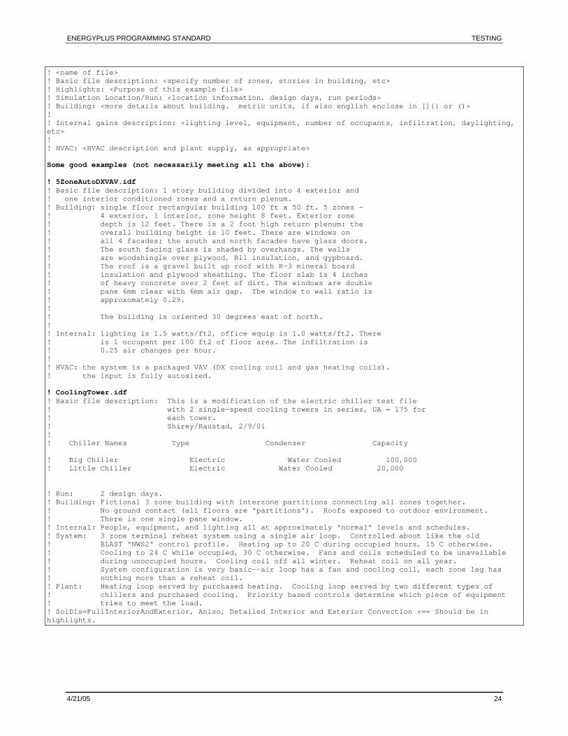
! <name of file> ! Basic file description: <specify number of zones, stories in building, etc> ! Highlights: <Purpose of this example file> ! Simulation Location/Run: <location information, design days, run periods> ! Building: <more details about building. metric units, if also english enclose in []{} or ()> ! ! Internal gains description: <lighting level, equipment, number of occupants, infiltration, daylighting, etc> ! ! HVAC: <HVAC description and plant supply, as appropriate> Some good examples (not necessarily meeting all the above): ! 5ZoneAutoDXVAV.idf ! Basic file description: 1 story building divided into 4 exterior and ! one interior conditioned zones and a return plenum. ! Building: single floor rectangular building 100 ft x 50 ft. 5 zones - ! 4 exterior, 1 interior, zone height 8 feet. Exterior zone ! depth is 12 feet. There is a 2 foot high return plenum: the ! overall building height is 10 feet. There are windows on ! all 4 facades; the south and north facades have glass doors. ! The south facing glass is shaded by overhangs. The walls ! are woodshingle over plywood, R11 insulation, and gypboard. ! The roof is a gravel built up roof with R-3 mineral board ! insulation and plywood sheathing. The floor slab is 4 inches ! of heavy concrete over 2 feet of dirt. The windows are double ! pane 6mm clear with 6mm air gap. The window to wall ratio is ! approxomately 0.29. ! ! The building is oriented 30 degrees east of north. ! ! Internal: lighting is 1.5 watts/ft2, office equip is 1.0 watts/ft2. There ! is 1 occupant per 100 ft2 of floor area. The infiltration is ! 0.25 air changes per hour. ! ! HVAC: the system is a packaged VAV (DX cooling coil and gas heating coils). ! the input is fully autosized. ! CoolingTower.idf ! Basic file description: This is a modification of the electric chiller test file ! with 2 single-speed cooling towers in series, UA = 175 for ! each tower. ! Shirey/Raustad, 2/9/01 ! ! Chiller Names Type Condenser Capacity ! Big Chiller Electric Water Cooled 100,000 ! Little Chiller Electric Water Cooled 20,000 ! Run: 2 design days. ! Building: Fictional 3 zone building with interzone partitions connecting all zones together. ! No ground contact (all floors are "partitions"). Roofs exposed to outdoor environment. ! There is one single pane window. ! Internal: People, equipment, and lighting all at approximately "normal" levels and schedules. ! System: 3 zone terminal reheat system using a single air loop. Controlled about like the old ! BLAST "NWS2" control profile. Heating up to 20 C during occupied hours, 15 C otherwise. ! Cooling to 24 C while occupied, 30 C otherwise. Fans and coils scheduled to be unavailable ! during unoccupied hours. Cooling coil off all winter. Reheat coil on all year. ! System configuration is very basic--air loop has a fan and cooling coil, each zone leg has ! nothing more than a reheat coil. ! Plant: Heating loop served by purchased heating. Cooling loop served by two different types of ! chillers and purchased cooling. Priority based controls determine which piece of equipment ! tries to meet the load. ! SolDis=FullInteriorAndExterior, Aniso, Detailed Interior and Exterior Convection <== Should be in highlights.
ENERGYPLUS PROGRAMMING STANDARD APPENDIX A: DEFINITIONS AND NOTATION
4/21/05 25
Appendix A: Definitions and Notation
The following definitions will be applicable for this document: EnergyPlus — The name of the program chosen by team members to represent the best
pieces of the DOE-2 and (I)BLAST programs. EnergyPlus as defined by the team members is only responsible for performing building energy analysis. It will not serve either as a user interface or as an output processor. This will have some bearing on the topics detailed in this standard.
Legacy Code — Program code from (I)BLAST and DOE-2 which will not be revised (no algorithm changes) for reasons of time constraints, testing considerations, etc.
Reverse Engineering — The process of determining the data flow and algorithms used for various program codes.
Reengineered Code — Code which has been reverse engineered and then modified to fit the proposed guidelines agreed upon by the team members. The starting point for reengineered code is code from either (I)BLAST or DOE-2.
New Code — Code which has been written from scratch, i.e., completely new code.
Superblock — A grouping of modules with a common purpose. All of the heat balance modules would be considered part of the heat balance superblock; system modules would be part of a system superblock, etc.
FORTRAN90/95 or F90/95 — This refers to the full ANSI Fortran 90 language as defined in the American National Standard Programming Language Fortran 90, ANSI X3.198-1992 and International Standards Organization Programming Language Fortran, ISO/IEC 1539:1991(E). F95 is a slightly revised standard – a bit later than F90. F2000 is a later standard than F95 and contains some substantial revisions.
FORTRAN90 Strict — Strict means that the code adheres to at least the FORTRAN77 standard and includes new features of FORTRAN90.
FORTRAN90 Pure — Pure means that the code does not contain any of the features that have been ruled obsolete by the FORTRAN90 standard.
Verb-Predicate Rule — A method for naming subroutines consistently and logically based on the functionality of the routine. Every subroutine performs some action (the “verb”) on a particular item or data set (the “predicate”). The subroutine name is thus constructed using the verb-predicate combination to arrive at a unique name for a particular algorithm.
ANSI – American National Standards Institute
ENERGYPLUS PROGRAMMING STANDARD APPENDIX B: DEVELOPMENT OF THE STANDARD
4/21/05 26
Appendix B: Development of the Standard
Why Standards?
Standard: An acknowledged measure of comparison for quantitative or qualitative value; a criterion. 1
Without standards, software development is an uncontrolled activity or, often, an activity out of control. With standards, the quality of software within the development group can continuously improve to the detriment of no individual contribution. In addition, standards may be able to help us meet various goals for the development (such as cost, timeliness, and focus on the product). At the July 1995, joint team meeting2, several goals for the project were outlined: 1) Take best of existing DOE-2/BLAST/(IBLAST) capabilities, applications, and
methods/structures. Combine with existing best of others. 2) Reuse existing code and structures where possible. 3) Short Time Frames (< 24 months) During April 1996, the "Champaign Best of" group met and determined priorities for development within, at least, their portion of the "Best of" development. Using a list3, the following weightings were determined, in descending order of importance (Level 1 more important than Level 2): Level 1: Maintainability, Robustness, Reliability, Testability,
Understandability(Readability)
Level 2: Portability, Reusability
Level 3: Speed, Size Thus, we established a standard both for coders as well as for reviewers. When we code or review, we will try to keep these elements in mind. Should a trade-off be needed, the decision either at coding time or review time will fall to the priorities established. These items are defined (for the most part) in Code Complete4 along with a table that shows how focus on one may hinder another. The pertinent definitions are repeated here:
Maintainability: The ease with which you can modify a software system to change or add capabilities, improve performance, or correct defects.
Robustness: The degree to which a system continues to function in the presence of invalid inputs or stressful environmental conditions.
Reliability: The ability of a system to perform its required function under stated conditions whenever required -- having a long mean time between failures.
1 The American Heritage® Dictionary of the English Language, Third Edition copyright © 1992 by Houghton Mifflin Company. Electronic version licensed from InfoSoft International, Inc. All rights reserved. 2 Meeting Notes, Dru Crawley, attachments to mail messages. 3 Debugging the Development Process, Steve Maguire, Microsoft Press, ©1993. 4 Code Complete: A Practical Handbook of Software Construction, Steve McConnell, Microsoft Press, ©1993, pp 557-560.
ENERGYPLUS PROGRAMMING STANDARD APPENDIX B: DEVELOPMENT OF THE STANDARD
4/21/05 27
Testability: The degree to which you can unit-test and system-test a system; the degree to which you can verify that the system meets its requirements.
Understandability: The ease with which you can comprehend a system at both the system-organizational and detailed-statement levels. Understandability has to do with the coherence of the system at a more general level than readability does.
Portability: The ease with which you can modify a system to operate in an environment different from that for which it was specifically designed.
Reusability: The extent to which and the ease with which you can use parts of a system in other system.
Speed: Related to Efficiency: execution time.
Size: Related to Efficiency: memory requirements. Not on our original list but included in the reference:
• Efficiency: Minimal use of system resources, including memory and execution time.
• Readability: The ease with which you can read and understand the source code of a system, especially at the detailed-statement level.
• Accuracy: The degree to which a system, as built, is free from error, especially with respect to quantitative outputs. Accuracy differs from correctness; it is a determination of how well a system does the job it is built for rather than whether it was built correctly.
At the same time, we should consider what our references put forth.5 “Standards shouldn’t be imposed at all, if you can avoid them. Consider the alternatives to standards: flexible guidelines, a collection of suggestions rather than guidelines, or a set of examples that embody the best practices.”
What Standards?
Standards are being established for development work as well as for language coding. This document will primarily speak to the standards and guidelines of language coding (currently FORTRAN90). We are also establishing less formal (and more formal) techniques within the groups: design and code reviews, design and code walk-throughs, automated version control (both for source code and documents), and other practices that generally affect the quality of software products.
Application of the Standard
How does one measure whether an item “meets” the standard? It could be said that:
One must measure objectively. Ideally, it would be automated either through the compiler used or the use of an auxiliary program if it didn’t require too many resources to set-up.
As some examples of concepts that encourage good coding, Code Complete5 puts forth the following techniques as being useful: 1. Assign two people to every part of the program. 2. Review every line of code. 3. Require code sign-offs. 4. Route good code examples for review. 5. Emphasize that code listings are public assets.
5 Code Complete: A Practical Handbook of Software Construction, Steve McConnell, Microsoft Press, ©1993, pp 528-530.
ENERGYPLUS PROGRAMMING STANDARD APPENDIX B: DEVELOPMENT OF THE STANDARD
4/21/05 28
6. Reward good code. 7. An easy standard: Make the code readable! This document will provide further information on ideas from various team members on producing good, consistent code for the EnergyPlus project. However, it should be remembered by all that the EnergyPlus project will rely heavily on the discipline and discretion of the various team members to conform to the guidelines established in this document as much as possible. Much of the information in this document will lean towards a “guideline” rather than a “standard”. The intention is to keep the code as uniform as possible without imposing too many rigid rules that in and of themselves become a hindrance to the successful completion of the project.
Metrics
Metric: A standard of measurement.1 Metric is another way of saying “standard”. Sections under this topic will illustrate various measures that might be applied to source code, documentation, user interface and other elements of a system. Referring to Code Complete6, “the term ‘metrics’ refers to any measurement related to software development. Lines of code, number of defects, defects per...” and gives two solid reasons to measure the software development process: 1) Any way of measuring the process is superior to not measuring it at all. 2) To argue against metrics is to argue that it is better not to know what is really happening
on your project. Metrics are not an “absolute”; rather, they are methods for showing “abnormalities” that may need to be looked at to preserve quality code. In many cases, we will rely on the code reviewers subjective opinion on the understandability of the code. Listed below are some example metrics that developers might want to use as guides when writing EnergyPlus code. It is suggested that developers take some of the ideas from each of these and apply them to their coding assignments.
Complexity Metric
A complexity metric can be used rather than specify a number of lines that must be contained in a piece of source code. McCabe's technique for measuring complexity can probably be automated and has been correlated to reliability and frequent errors.7 The metric is simple, straightforward, and described in the following table.
6 Code Complete: A Practical Handbook of Software Construction, Steve McConnell, Microsoft Press, ©1993, pp 544-547. 7 Code Complete: A Practical Handbook of Software Construction, Steve McConnell, Microsoft Press, ©1993, pp 395-396.
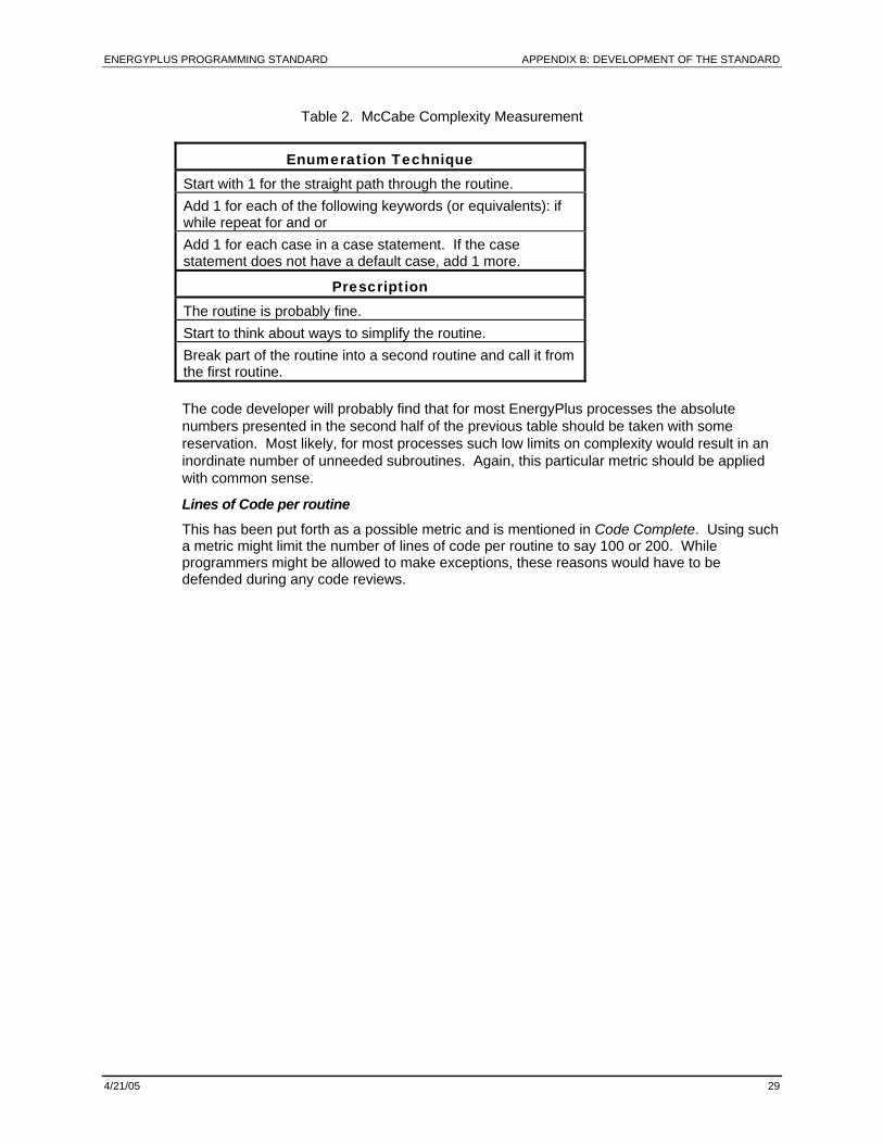
ENERGYPLUS PROGRAMMING STANDARD APPENDIX B: DEVELOPMENT OF THE STANDARD
4/21/05 29
Table 2. McCabe Complexity Measurement
Enumeration Technique Start with 1 for the straight path through the routine. Add 1 for each of the following keywords (or equivalents): if while repeat for and or Add 1 for each case in a case statement. If the case statement does not have a default case, add 1 more.
Prescription The routine is probably fine. Start to think about ways to simplify the routine. Break part of the routine into a second routine and call it from the first routine. The code developer will probably find that for most EnergyPlus processes the absolute numbers presented in the second half of the previous table should be taken with some reservation. Most likely, for most processes such low limits on complexity would result in an inordinate number of unneeded subroutines. Again, this particular metric should be applied with common sense.
Lines of Code per routine This has been put forth as a possible metric and is mentioned in Code Complete. Using such a metric might limit the number of lines of code per routine to say 100 or 200. While programmers might be allowed to make exceptions, these reasons would have to be defended during any code reviews.
ENERGYPLUS PROGRAMMING STANDARD APPENDIX C: EVOLUTIONARY REENGINEERING
4/21/05 30
Appendix C: Evolutionary Reengineering
Evolutionary reengineering, or ER, might be defined as a process of slowly and selectively introducing new structured code in with legacy code. This process is to start out at the lowest level of module detail and slowly filter one “branch” up through the structure of the program until the main drivers are accessed. By testing a single branch of the module tree in each of the main sections of the code, it can be determined more quickly if the module structure that is being proposing for each section is valid.
This strategy is in some respects the opposite of starting with a clean slate and then trying to piece together the program. In effect, it moves incrementally from old unstructured legacy code to new modular code by incorporating the new code with the old. The existing code retains its capability to interface with the user input data, and is extended to generate parameters needed by the new code modules. In this way, the new modules can be verified without having to completely replace the entire functional capability of the old program with new code before any verification can take place. As the process proceeds, the parameters being supplied by old routines can be supplanted by those available from new routines and new data structures. This makes the transition evolutionary, and permits a smooth transition with a greater capability for verification testing. One main advantage of ER is that there will always be a working version of EnergyPlus available. One slight disadvantage is that there may be the need for temporary scaffolding code to transition from the mixed mode to fully modular code.
The process is shown schematically in the following figure as a series of four stages. The first stage is the starting point with legacy code and traditional input and output. The second stage, which could consist of several substages, incorporates new structured code with the legacy code. This new code receives all needed inputs from the legacy code, and produces only developers’ verification output. This stage is considered complete when it includes the fundamental initial modules, and has defined interfaces for new plug-in modules. In the third stage, the new input data structure is included to supply input to the structured code modules, which have been algorithmically verified. In the fourth stage, the new output data structure is incorporated, and the transition is complete.
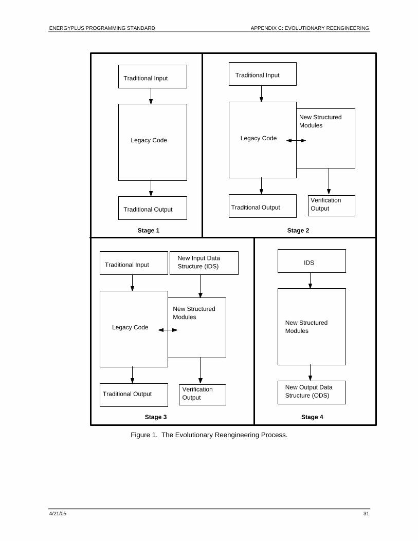
ENERGYPLUS PROGRAMMING STANDARD APPENDIX C: EVOLUTIONARY REENGINEERING
4/21/05 31
Legacy Code
Traditional Input
Traditional Output
Legacy Code
New Structured Modules
Stage 1 Stage 2
Verification Output
IDS
New Structured Modules
Stage 4
Legacy Code
New Structured Modules
Verification Output
New Input Data Structure (IDS)
New Output Data Structure (ODS)
Traditional Input
Traditional Output
Traditional Output
Traditional Input
Stage 3
Figure 1. The Evolutionary Reengineering Process.
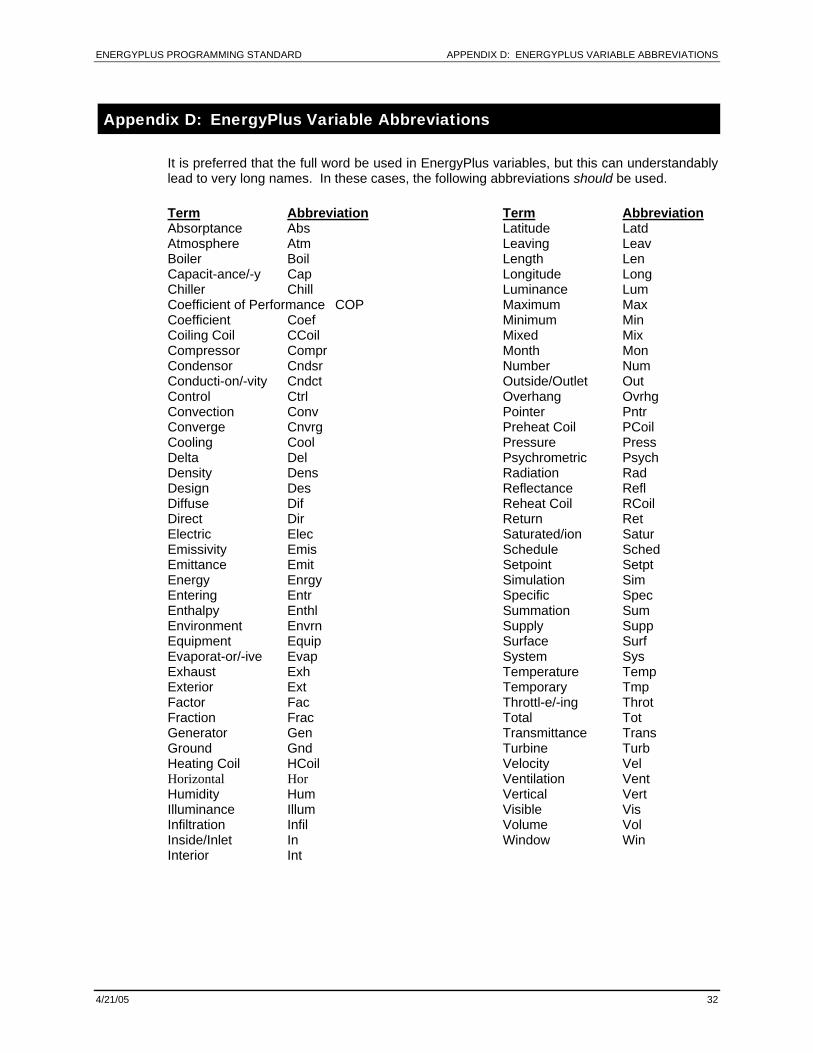
ENERGYPLUS PROGRAMMING STANDARD APPENDIX D: ENERGYPLUS VARIABLE ABBREVIATIONS
4/21/05 32
Appendix D: EnergyPlus Variable Abbreviations
It is preferred that the full word be used in EnergyPlus variables, but this can understandably lead to very long names. In these cases, the following abbreviations should be used. Term Abbreviation Absorptance Abs Atmosphere Atm Boiler Boil Capacit-ance/-y Cap Chiller Chill Coefficient of Performance COP Coefficient Coef Coiling Coil CCoil Compressor Compr Condensor Cndsr Conducti-on/-vity Cndct Control Ctrl Convection Conv Converge Cnvrg Cooling Cool Delta Del Density Dens Design Des Diffuse Dif Direct Dir Electric Elec Emissivity Emis Emittance Emit Energy Enrgy Entering Entr Enthalpy Enthl Environment Envrn Equipment Equip Evaporat-or/-ive Evap Exhaust Exh Exterior Ext Factor Fac Fraction Frac Generator Gen Ground Gnd Heating Coil HCoil Horizontal Hor Humidity Hum Illuminance Illum Infiltration Infil Inside/Inlet In Interior Int
Term Abbreviation Latitude Latd Leaving Leav Length Len Longitude Long Luminance Lum Maximum Max Minimum Min Mixed Mix Month Mon Number Num Outside/Outlet Out Overhang Ovrhg Pointer Pntr Preheat Coil PCoil Pressure Press Psychrometric Psych Radiation Rad Reflectance Refl Reheat Coil RCoil Return Ret Saturated/ion Satur Schedule Sched Setpoint Setpt Simulation Sim Specific Spec Summation Sum Supply Supp Surface Surf System Sys Temperature Temp Temporary Tmp Throttl-e/-ing Throt Total Tot Transmittance Trans Turbine Turb Velocity Vel Ventilation Vent Vertical Vert Visible Vis Volume Vol Window Win