engine controls - adriatic company engine... · dtc p0463 fuel level sensor high voltage 1f-222 dtc...
TRANSCRIPT

DAEWOO M-150 BL2
SECTION 1F
ENGINE CONTROLS
CAUTION: Disconnect the negative battery cable before removing or installing any electrical unit or when atool or equipment could easily come in contact with exposed electrical terminals. Disconnecting this cablewill help prevent personal injury and damage to the vehicle. The ignition must also be in LOCK unlessotherwise noted.
TABLE OF CONTENTSDescription and Operation 1F-4. . . . . . . . . . . . . . . . . .
Ignition System Operation 1F-4. . . . . . . . . . . . . . . . . .
Electronic Ignition System Ignition Coil 1F-4. . . . . . .
Crankshaft Position Sensor 1F-4. . . . . . . . . . . . . . . . .
Camshaft Position Sensor 1F-4. . . . . . . . . . . . . . . . . .
Idle Air System Operation 1F-4. . . . . . . . . . . . . . . . . .
Fuel Control System Operation 1F-4. . . . . . . . . . . . . .
Evaporative Emission Control System Operation 1F-5. . . . . . . . . . . . . . . . . . . . . . . . . . . . . .
Controlled Charcoal Canister 1F-5. . . . . . . . . . . . . . . .
Positive Crankcase Ventilation Control SystemOperation 1F-5. . . . . . . . . . . . . . . . . . . . . . . . . . . . . .
Engine Coolant Temperature Sensor 1F-6. . . . . . . . .
Throttle Position Sensor 1F-6. . . . . . . . . . . . . . . . . . . .
Catalyst Monitor Oxygen Sensors 1F-6. . . . . . . . . . .
Electric Exhaust Gas Recirculation Valve 1F-6. . . . .
Intake Air Temperature Sensor 1F-7. . . . . . . . . . . . . .
Idle Air Control Valve 1F-7. . . . . . . . . . . . . . . . . . . . . .
Manifold Absolute Pressure Sensor 1F-7. . . . . . . . . .
Engine Control Module 1F-8. . . . . . . . . . . . . . . . . . . . .
Fuel Injector 1F-8. . . . . . . . . . . . . . . . . . . . . . . . . . . . . .
Fuel Cutoff Switch (Inertia Switch) 1F-8. . . . . . . . . . .
Knock Sensor 1F-8. . . . . . . . . . . . . . . . . . . . . . . . . . . . .
Variable Reluctance (VR) Sensor 1F-8. . . . . . . . . . . .
Octane Number Connector 1F-8. . . . . . . . . . . . . . . . .
Strategy-Based Diagnostics 1F-9. . . . . . . . . . . . . . . .
EOBD Serviceability Issues 1F-9. . . . . . . . . . . . . . . . .
Serial Data Communications 1F-10. . . . . . . . . . . . . . .
Euro On-Board Diagnostic (EOBD) 1F-10. . . . . . . . .
Comprehensive Component Monitor DiagnosticOperation 1F-11. . . . . . . . . . . . . . . . . . . . . . . . . . . . .
Common EOBD Terms 1F-11. . . . . . . . . . . . . . . . . . . .
DTC Types 1F-13. . . . . . . . . . . . . . . . . . . . . . . . . . . . . .
Reading Diagnostic Trouble Codes 1F-13. . . . . . . . .
Primary System-Based Diagnostics 1F-15. . . . . . . .
Diagnostic Information and Procedures 1F-17. . . .
System Diagnosis 1F-17. . . . . . . . . . . . . . . . . . . . . . . . . .
Diagnostic Aids 1F-17. . . . . . . . . . . . . . . . . . . . . . . . . .
Idle Learn Procedure 1F-17. . . . . . . . . . . . . . . . . . . . .
Euro On-Board Diagnostic (EOBD) System Check 1F-18. . . . . . . . . . . . . . . . . . . . . . . . . . . . . . . .
ECM Output Diagnosis 1F-20. . . . . . . . . . . . . . . . . . . .
Multiple ECM Information Sensor DTCs Set 1F-21. .
Engine Cranks But Will Not Run 1F-25. . . . . . . . . . . .
No Malfunction Indicator Lamp 1F-30. . . . . . . . . . . . .
Malfunction Indicator Lamp On Steady 1F-32. . . . . .
Fuel System Diagnosis 1F-34. . . . . . . . . . . . . . . . . . . .
Fuel Pump Relay Circuit Check 1F-36. . . . . . . . . . . .
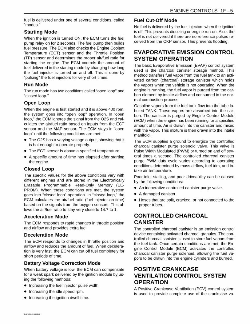
Main Relay Circuit Check 1F-38. . . . . . . . . . . . . . . . . .
Manifold Absolute Pressure Check 1F-40. . . . . . . . . .
Idle Air Control System Check 1F-42. . . . . . . . . . . . .
Ignition System Check 1F-45. . . . . . . . . . . . . . . . . . . .
Engine Cooling Fan Circuit Check 1F-48. . . . . . . . . .
Data Link Connector Diagnosis 1F-52. . . . . . . . . . . . .
Fuel Injector Balance Test 1F-54. . . . . . . . . . . . . . . . .
Diagnostic Trouble Code Diagnosis 1F-55. . . . . . . . Clearing Trouble Codes 1F-55. . . . . . . . . . . . . . . . . . . Diagnostic Trouble Codes 1F-55. . . . . . . . . . . . . . . . . DTC P0107 Manifold Absolute Pressure Sensor
Low Voltage 1F-58. . . . . . . . . . . . . . . . . . . . . . . . . . . DTC P0108 Manifold Pressure Sensor High
Voltage 1F-62. . . . . . . . . . . . . . . . . . . . . . . . . . . . . . . DTC P0112 Intake Air Temperature Sensor Low
Voltage 1F-66. . . . . . . . . . . . . . . . . . . . . . . . . . . . . . . DTC P0113 Intake Air Temperature Sensor High
Voltage 1F-68. . . . . . . . . . . . . . . . . . . . . . . . . . . . . . . DTC P0117 Engine Coolant Temperature Sensor
Low Voltage 1F-72. . . . . . . . . . . . . . . . . . . . . . . . . . . DTC P0118 Engine Coolant Temperature Sensor
High Voltage 1F-74. . . . . . . . . . . . . . . . . . . . . . . . . . .

1F – 2 ENGINE CONTROLS
DAEWOO M-150 BL2
DTC P0122 Throttle Position Sensor Low Voltage 1F-76. . . . . . . . . . . . . . . . . . . . . . . . . . . . . . .
DTC P0123 Throttle Position Sensor High Voltage 1F-80. . . . . . . . . . . . . . . . . . . . . . . . . . . . . . .
DTC P0131 Oxygen Sensor Low Voltage 1F-84. . . . DTC P0132 Oxygen Sensor High Voltage 1F-88. . . . DTC P0133 Oxygen Sensor No Activity 1F-90. . . . . DTC P0137 Heated Oxygen Sensor Low
Voltage 1F-94. . . . . . . . . . . . . . . . . . . . . . . . . . . . . . . DTC P0138 Heated Oxygen Sensor High
Voltage 1F-98. . . . . . . . . . . . . . . . . . . . . . . . . . . . . . . DTC P0140 Heated Oxygen Sensor
No Activity 1F-100. . . . . . . . . . . . . . . . . . . . . . . . . . . . DTC P0141 Heated Oxygen Sensor
Heater Malfunction 1F-104. . . . . . . . . . . . . . . . . . . . DTC P0171 Fuel Trim System Too Lean 1F-106. . . . DTC P0172 Fuel Trim System Too Rich 1F-109. . . . DTC P1230 Fuel Pump Relay Low Voltage 1F-114. DTC P1231 Fuel Pump Relay High Voltage 1F-118. DTC P0261 Injector 1 Low Voltage 1F-122. . . . . . . . DTC P0262 Injector 1 High Voltage 1F-124. . . . . . . . DTC P0264 Injector 2 Low Voltage 1F-126. . . . . . . . DTC P0265 Injector 2 High Voltage 1F-128. . . . . . . . DTC P0267 Injector 3 Low Voltage 1F-130. . . . . . . . DTC P0268 Injector 3 High Voltage 1F-132. . . . . . . . DTC P0300 Multiple Cylinder Misfire 1F-135. . . . . . . DTC P0300 Multiple Cylinder Misfire 1F-139. . . . . . . DTC P1320 Crankshaft Segment Period
Segment adaptation At Limit 1F-142. . . . . . . . . . . . DTC P1321 Crankshaft Segment Period
Tooth Error 1F-144. . . . . . . . . . . . . . . . . . . . . . . . . . . DTC P0327 Knock Sensor Circuit Fault 1F-146. . . . DTC P0335 Magnetic Crankshaft Position
Sensor Electrical Error 1F-150. . . . . . . . . . . . . . . . . DTC P0336 58X Crankshaft Position Sensor
No Plausible Signal 1F-152. . . . . . . . . . . . . . . . . . . . DTC P0337 58X Crankshaft Position Sensor
No Signal 1F-154. . . . . . . . . . . . . . . . . . . . . . . . . . . . DTC P0341 Camshaft Position Sensor
Rationality 1F-156. . . . . . . . . . . . . . . . . . . . . . . . . . . . DTC P0342 Camshaft Position Sensor
No Signal 1F-158. . . . . . . . . . . . . . . . . . . . . . . . . . . . DTC P0351 Ignition Signal Coil A Fault 1F-160. . . . . DTC P0352 Ignition Signal Coil B Fault 1F-162. . . . . DTC P0353 Ignition Signal Coil C Fault 1F-164. . . . . DTC P1382 Rough Road Data
Invalid (Non ABS) 1F-166. . . . . . . . . . . . . . . . . . . . . DTC P1382 Rough Road Data Invalid (ABS) 1F-170DTC P1385 Rough Road Sensor Circuit Fault
(Non ABS) 1F-174. . . . . . . . . . . . . . . . . . . . . . . . . . . DTC P1385 Rough Road Sensor Circuit Fault
(ABS) 1F-178. . . . . . . . . . . . . . . . . . . . . . . . . . . . . . . .
DTC P0400 Exhaust Gas Recirculation Out Of Limit 1F-182. . . . . . . . . . . . . . . . . . . . . . . . . .
DTC P1402 Exhaust Gas Recirculation Blocked 1F-186. . . . . . . . . . . . . . . . . . . . . . . . . . . . . .
DTC P1403 Exhaust Gas Recirculation Valve Failure 1F-188. . . . . . . . . . . . . . . . . . . . . . . . . .
DTC P0404 Exhaust Gas Recirculation Opened 1F-192. . . . . . . . . . . . . . . . . . . . . . . . . . . . . .
DTC P1404 Exhaust Gas Recirculation Closed 1F-196. . . . . . . . . . . . . . . . . . . . . . . . . . . . . . .
DTC P0405 EEGR Pintle Position Sensor Low Voltage 1F-200. . . . . . . . . . . . . . . . . . . . . . . . . .
DTC P0406 EEGR Pintle Position Sensor High Voltage 1F-204. . . . . . . . . . . . . . . . . . . . . . . . . .
DTC P0420 Catalyst Low Efficiency 1F-208. . . . . . . . DTC P0444 EVAP Purge Control Circuit
No Signal 1F-210. . . . . . . . . . . . . . . . . . . . . . . . . . . . DTC P0445 EVAP Purge Control Fault 1F-214. . . . . DTC P0462 Fuel Level Sensor Low Voltage 1F-218. DTC P0463 Fuel Level Sensor High Voltage 1F-222DTC P0480 Low Speed Cooling Fan Relay
Circuit Fauit (Without A/C) 1F-226. . . . . . . . . . . . . . DTC P0480 Low Speed Cooling Fan Relay
Circuit Fauit (With A/C) 1F-230. . . . . . . . . . . . . . . . . DTC P0481 High Speed Cooling Fan Relay
Circuit Fauit (Without A/C) 1F-234. . . . . . . . . . . . . . DTC P0481 High Speed Cooling Fan Relay
Circuit Fauit (With A/C) 1F-238. . . . . . . . . . . . . . . . . DTC P0501 Vehicle Speed No Signal
(M/T Only) 1F-242. . . . . . . . . . . . . . . . . . . . . . . . . . . . DTC P1505 Idle Air Control Valve (IACV)
Error 1F-246. . . . . . . . . . . . . . . . . . . . . . . . . . . . . . . . . DTC P1535 Evaporator Temperature Sensor
High Voltage 1F-250. . . . . . . . . . . . . . . . . . . . . . . . . . DTC P1536 Evaporator Temperature Sensor
Low Voltage 1F-252. . . . . . . . . . . . . . . . . . . . . . . . . . DTC P1537 A/C Compressor Relay High
Voltage 1F-254. . . . . . . . . . . . . . . . . . . . . . . . . . . . . . DTC P1538 A/C Compressor Relay Low
Voltage 1F-256. . . . . . . . . . . . . . . . . . . . . . . . . . . . . . DTC P0562 System Voltage (Engine Side)
Too Low 1F-258. . . . . . . . . . . . . . . . . . . . . . . . . . . . . . DTC P0563 System Voltage (Engine Side)
Too High 1F-260. . . . . . . . . . . . . . . . . . . . . . . . . . . . . DTC P0601 Engine Control Module Chechsum
Error 1F-262. . . . . . . . . . . . . . . . . . . . . . . . . . . . . . . . . DTC P0604 Engine Control Module Internal/
External RAM Error 1F-263. . . . . . . . . . . . . . . . . . . . DTC P0605 Engin Control Module NMVY
Write Error 1F-264. . . . . . . . . . . . . . . . . . . . . . . . . . . DTC P1610 Main Relay High Voltage 1F-266. . . . . . DTC P1611 Main Relay Low Voltage 1F-268. . . . . . .
ENGINE CONTROLS 1F – 3
DAEWOO M-150 BL2
DTC P1628 Immobilizer No Successful Communication 1F-270. . . . . . . . . . . . . . . . . . . . . . .
DTC P1629 Immovilizer Wrong Computation 1F-272DTC P0656 Fuel Level Gauge Circuit Fault 1F-274. DTC P1660 Malfunction Indicator Lamp (MIL)
High Voltage 1F-276. . . . . . . . . . . . . . . . . . . . . . . . . . DTC P1661 Malfunction Indicator Lamp (MIL)
Low Voltage 1F-278. . . . . . . . . . . . . . . . . . . . . . . . . .
Symptom Diagnosis 1F-280. . . . . . . . . . . . . . . . . . . . . . Important Preliminary Checks 1F-280. . . . . . . . . . . . . Intermittent 1F-281. . . . . . . . . . . . . . . . . . . . . . . . . . . . . Hard Start 1F-283. . . . . . . . . . . . . . . . . . . . . . . . . . . . . . Surges or Chuggles 1F-286. . . . . . . . . . . . . . . . . . . . . Lack of Power, Sluggishness or Sponginess 1F-288Detonation/Spark Knock 1F-290. . . . . . . . . . . . . . . . . . Hesitation, Sag, Stumble 1F-292. . . . . . . . . . . . . . . . . Cuts Out, Misses 1F-294. . . . . . . . . . . . . . . . . . . . . . . . Poor Fuel Economy 1F-296. . . . . . . . . . . . . . . . . . . . . . Rough, Unstable, or Incorrect Idle, Stalling 1F-297. . Excessive Exhaust Emissions or Odors 1F-300. . . . Dieseling, Run-on 1F-302. . . . . . . . . . . . . . . . . . . . . . . Backfire 1F-303. . . . . . . . . . . . . . . . . . . . . . . . . . . . . . . .
Maintenance and Repair 1F-304. . . . . . . . . . . . . . . . . . On-Vehicle Service 1F–304. . . . . . . . . . . . . . . . . . . . . . .
Fuel Pump 1F–304. . . . . . . . . . . . . . . . . . . . . . . . . . . . Fuel Pressure Regulator 1F-305. . . . . . . . . . . . . . . . . Fuel Filter 1F-306. . . . . . . . . . . . . . . . . . . . . . . . . . . . . . Fuel Tank 1F-307. . . . . . . . . . . . . . . . . . . . . . . . . . . . . . Fuel Rail and Injectors 1F-308. . . . . . . . . . . . . . . . . . . Evaporator Emission Canister 1F-309. . . . . . . . . . . . .
Evaporator Emission Canister Purge Solenoid 1F-310. . . . . . . . . . . . . . . . . . . . . . . . . . . . .
Manifold Absolute Pressure (MAP) Sensor 1F-310. . Throttle Body 1F-311. . . . . . . . . . . . . . . . . . . . . . . . . . . Engine Coolant Temperature (ECT) Sensor 1F-312. Intake Air Temperature (ECT) Sensor 1F-313. . . . . . Oxygen Sensor (O2S 1) 1F-314. . . . . . . . . . . . . . . . . . Heated Oxygen Sensor (HO2S 2) 1F-314. . . . . . . . . Electric Exhaust Gas Recirculation (EEGR)
Valve 1F-315. . . . . . . . . . . . . . . . . . . . . . . . . . . . . . . . Knock Sensor 1F-315. . . . . . . . . . . . . . . . . . . . . . . . . . . Electronic Ignition (EI) System Ignition Coil 1F-316. Crankshaft Position (CKP) Sensor 1F-316. . . . . . . . Camshaft Position (CMP) Sensor 1F-317. . . . . . . . . . Engine Control Module (ECM) 1F-317. . . . . . . . . . . . .
Specifications 1F-319. . . . . . . . . . . . . . . . . . . . . . . . . . . Fastener Tightening Specification 1F-319. . . . . . . . . .
Special Tools 1F-319. . . . . . . . . . . . . . . . . . . . . . . . . . . . Special Tools Table 1F-319. . . . . . . . . . . . . . . . . . . . . .
Schematic and Routing Diagrams 1F-320. . . . . . . . . ECM Wiring Diagram
(Sirius D3 – 1 of 5) 1F-320. . . . . . . . . . . . . . . . . . . . ECM Wiring Diagram
(Sirius D3 – 2 of 5) 1F-321. . . . . . . . . . . . . . . . . . . . ECM Wiring Diagram
(Sirius D3 – 3 of 5) 1F-322. . . . . . . . . . . . . . . . . . . . ECM Wiring Diagram
(Sirius D3 – 4 of 5) 1F-323. . . . . . . . . . . . . . . . . . . . ECM Wiring Diagram
(Sirius D3 – 5 of 5) 1F-324. . . . . . . . . . . . . . . . . . . .

1F – 4 ENGINE CONTROLS
DAEWOO M-150 BL2
DESCRIPTION AND OPERATIONIGNITION SYSTEM OPERATIONThis ignition system does not use a conventional distrib-utor and coil. It uses a crankshaft position sensor inputto the Engine Control Module (ECM). The ECM then de-termines Electronic Spark Timing (EST) and triggers theelectronic ignition system ignition coil.
This type of distributorless ignition system uses a “wastespark’’ method of spark distribution. Each cylinder is in-dividural with coil per cylinder.
These systems use the EST signal from the ECM tocontrol the EST. The ECM uses the following informa-tion:
Engine load (manifold pressure or vacuum).
Atmospheric (barometric) pressure.
Engine temperature.
Intake air temperature.
Crankshaft position.
Engine speed (rpm).
ELECTRONIC IGNITION SYSTEMIGNITION COILThe Electronic Ignition (EI) system ignition coil ismounted near on the cylinder head.
A terminals of the EI system ignition coil provides thespark for each spark plug. The EI system ignition coil isnot serviceable and must be replaced as an assembly.
CRANKSHAFT POSITION SENSORThis Electronic Ignition (EI) system uses a magneticcrankshaft position sensor. This sensor protrudesthrough its mount to within approximately 1.3 mm (0.05inch) of the crankshaft reluctor. The reluctor is a specialwheel attached to the crankshaft with 58 slots machinedinto it, 57 of which are equally spaced in 6-degree inter-vals. The last slot is wider and serves to generate a“sync pulse.” As the crankshaft rotates, the slots in thereluctor change the magnetic field of the sensor, creat-ing an induced voltage pulse. The longer pulse of the58th slot identifies a specific orientation of the crank-shaft and allows the Engine Control Module (ECM) todetermine the crankshaft orientation at all times. TheECM uses this information to generate timed ignitionand injection pulses that it sends to the ignition coils andto the fuel injectors.
CAMSHAFT POSITION SENSORThe Camshaft Position (CMP) sensor sends a CMP sig-nal to the Engine Control Module (ECM). The ECM usesthis signal as a “sync pulse” to trigger the injectors in theproper sequence. The ECM uses the CMP signal to indi-cate the position of the #1 piston during its power stroke.This allows the ECM to calculate true sequential fuel in-
jection mode of operation. If the ECM detects an incor-rect CMP signal while the engine is running, DiagnosticTrouble Code (DTC) P0341 will set. If the CMP signal islost while the engine is running, the fuel injection systemwill shift to a calculated sequential fuel injection modebased on the last fuel injection pulse, and the engine willcontinue to run. As long as the fault is present, the en-gine can be restarted. It will run in the calculated se-quential mode with a 1-in-6 chance of the injectorsequence being correct.
IDLE AIR SYSTEM OPERATIONThe idle air system operation is controlled by the baseidle setting of the throttle body and the Idle Air Control(IAC) valve.
The Engine Control Module (ECM) uses the IAC valve toset the idle speed dependent on conditions. The ECMuses information from various inputs, such as coolanttemperature, manifold vacuum, etc., for the effectivecontrol of the idle speed.
FUEL CONTROL SYSTEMOPERATIONThe function of the fuel metering system is to deliver thecorrect amount of fuel to the engine under all operatingconditions. The fuel is delivered to the engine by the in-dividual fuel injectors mounted into the intake manifoldnear each cylinder.
The main fuel control sensors are the Manifold AbsolutePressure (MAP) sensor, the oxygen sensor (O2S), andthe heated oxygen sensor (HO2S).
The MAP sensor measures or senses the intake man-ifold vacuum. Under high fuel demands, the MAP sensorreads a low vacuum condition, such as wide openthrottle. The Engine Control Module (ECM) uses this in-formation to enrich the mixture, thus increasing the fuelinjector on-time, to provide the correct amount of fuel.When decelerating, the vacuum increases. This vacuumchange is sensed by the MAP sensor and read by theECM, which then decreases the fuel injector on-timedue to the low fuel demand conditions.
The O2S is located in the exhaust manifold. The HO2Sis located in the exhaust pipe. The oxygen sensors indi-cate to the ECM the amount of oxygen in the exhaustgas, and the ECM changes the air/fuel ratio to the en-gine by controlling the fuel injectors. The best air/fuel ra-tio to minimize exhaust emissions is 14.7:1, whichallows the catalytic converter to operate most efficiently.Because of the constant measuring and adjusting of theair/fuel ratio, the fuel injection system is called a “closedloop” system.
The ECM uses voltage inputs from several sensors todetermine how much fuel to provide to the engine. The
ENGINE CONTROLS 1F – 5
DAEWOO M-150 BL2
fuel is delivered under one of several conditions, called“modes.’’
Starting ModeWhen the ignition is turned ON, the ECM turns the fuelpump relay on for 2 seconds. The fuel pump then buildsfuel pressure. The ECM also checks the Engine CoolantTemperature (ECT) sensor and the Throttle Position(TP) sensor and determines the proper air/fuel ratio forstarting the engine. The ECM controls the amount offuel delivered in the starting mode by changing how longthe fuel injector is turned on and off. This is done by“pulsing’’ the fuel injectors for very short times.
Run ModeThe run mode has two conditions called “open loop’’ and“closed loop.’’
Open LoopWhen the engine is first started and it is above 400 rpm,the system goes into “open loop’’ operation. In “openloop,’’ the ECM ignores the signal from the O2S and cal-culates the air/fuel ratio based on inputs from the ECTsensor and the MAP sensor. The ECM stays in ”openloop” until the following conditions are met:
The O2S has a varying voltage output, showing that itis hot enough to operate properly.
The ECT sensor is above a specified temperature.
A specific amount of time has elapsed after startingthe engine.
Closed LoopThe specific values for the above conditions vary withdifferent engines and are stored in the ElectronicallyErasable Programmable Read-Only Memory (EE-PROM). When these conditions are met, the systemgoes into “closed loop” operation. In “closed loop,” theECM calculates the air/fuel ratio (fuel injector on-time)based on the signals from the oxygen sensors. This al-lows the air/fuel ratio to stay very close to 14.7 to 1.
Acceleration ModeThe ECM responds to rapid changes in throttle positionand airflow and provides extra fuel.
Deceleration ModeThe ECM responds to changes in throttle position andairflow and reduces the amount of fuel. When decelera-tion is very fast, the ECM can cut off fuel completely forshort periods of time.
Battery Voltage Correction ModeWhen battery voltage is low, the ECM can compensatefor a weak spark delivered by the ignition module by us-ing the following methods:
Increasing the fuel injector pulse width.
Increasing the idle speed rpm.
Increasing the ignition dwell time.
Fuel Cut-Off ModeNo fuel is delivered by the fuel injectors when the ignitionis off. This prevents dieseling or engine run-on. Also, thefuel is not delivered if there are no reference pulses re-ceived from the CKP sensor. This prevents flooding.
EVAPORATIVE EMISSION CONTROLSYSTEM OPERATIONThe basic Evaporative Emission (EVAP) control systemused is the charcoal canister storage method. Thismethod transfers fuel vapor from the fuel tank to an acti-vated carbon (charcoal) storage canister which holdsthe vapors when the vehicle is not operating. When theengine is running, the fuel vapor is purged from the car-bon element by intake airflow and consumed in the nor-mal combustion process.
Gasoline vapors from the fuel tank flow into the tube la-beled TANK. These vapors are absorbed into the car-bon. The canister is purged by Engine Control Module(ECM) when the engine has been running for a specifiedamount of time. Air is drawn into the canister and mixedwith the vapor. This mixture is then drawn into the intakemanifold.
The ECM supplies a ground to energize the controlledcharcoal canister purge solenoid valve. This valve isPulse Width Modulated (PWM) or turned on and off sev-eral times a second. The controlled charcoal canisterpurge PWM duty cycle varies according to operatingconditions determined by mass airflow, fuel trim, and in-take air temperature.
Poor idle, stalling, and poor driveability can be causedby the following conditions:
An inoperative controlled canister purge valve.
A damaged canister.
Hoses that are split, cracked, or not connected to theproper tubes.
CONTROLLED CHARCOALCANISTERThe controlled charcoal canister is an emission controldevice containing activated charcoal granules. The con-trolled charcoal canister is used to store fuel vapors fromthe fuel tank. Once certain conditions are met, the En-gine Control Module (ECM) activates the controlledcharcoal canister purge solenoid, allowing the fuel va-pors to be drawn into the engine cylinders and burned.
POSITIVE CRANKCASEVENTILATION CONTROL SYSTEMOPERATIONA Positive Crankcase Ventilation (PCV) control systemis used to provide complete use of the crankcase va-

1F – 6 ENGINE CONTROLS
DAEWOO M-150 BL2
pors. Fresh air from the air cleaner is supplied to thecrankcase. The fresh air is mixed with blowby gaseswhich then pass through a vacuum hose into the intakemanifold.
Periodically inspect the hoses and the clamps. Replaceany crankcase ventilation components as required.
A restricted or plugged PCV hose may cause the follow-ing conditions:
Rough idle
Stalling or low idle speed
Oil leaks
Oil in the air cleaner
Sludge in the engine
A leaking PCV hose may cause the following conditions:
Rough idle
Stalling
High idle speed
ENGINE COOLANT TEMPERATURESENSORThe Engine Coolant Temperature (ECT) sensor is athermistor (a resistor which changes value based ontemperature) mounted in the engine coolant stream.Low coolant temperature produces a high resistance(100,000 ohms at –40C [–40F]) while high tempera-ture causes low resistance (70 ohms at 130C [266F]).
The Engine Control Module (ECM) supplies 5 volts tothe ECT sensor through a resistor in the ECM and mea-sures the change in voltage. The voltage will be highwhen the engine is cold and low when the engine is hot.By measuring the change in voltage, the ECM can de-termine the coolant temperature. The engine coolanttemperature affects most of the systems that the ECMcontrols. A failure in the ECT sensor circuit should set aDiagnostic Trouble Code (DTC) P0117 or P0118. Re-member, these DTC indicate a failure in the ECT circuit,so proper use of the chart will lead either to repairing awiring problem or to replacing the sensor to repair aproblem properly.
THROTTLE POSITION SENSORThe Throttle Position (TP) sensor is a potentiometerconnected to the throttle shaft of the throttle body. TheTP sensor electrical circuit consists of a 5-volt supplyline and a ground line, both provided by the Engine Con-trol Module (ECM). The ECM calculates the throttleposition by monitoring the voltage on this signal line. TheTP sensor output changes as the accelerator pedal ismoved, changing the throttle valve angle. At a closedthrottle position, the output of the TP sensor is low,about 0.4–0.8 volt. As the throttle valve opens, the out-put increases so that, at Wide Open Throttle (WOT), theoutput voltage will be about 4.5–5 volts.
The ECM can determine fuel delivery based on throttlevalve angle (driver demand). A broken or loose TP sen-sor can cause intermittent bursts of fuel from the injectorand an unstable idle, because the ECM thinks thethrottle is moving. A problem in any of the TP sensor cir-cuits should set a Diagnostic Trouble Code (DTC)P0122 or P0123. Once the DTC is set, the ECM will sub-stitute a default value for the TP sensor and some ve-hicle performance will return.
CATALYST MONITOR OXYGENSENSORSThree-way catalytic converters are used to control emis-sions of hydrocarbons (HC), carbon monoxide (CO),and oxides of nitrogen (NOx). The catalyst within theconverters promotes a chemical reaction. This reactionoxidizes the HC and CO present in the exhaust gas andconverts them into harmless water vapor and carbondioxide. The catalyst also reduces NOx by converting itto nitrogen. The ECM can monitor this process using theoxygen sensor (O2S) and heated oxygen sensor(HO2S). These sensors produce an output signal whichindicates the amount of oxygen present in the exhaustgas entering and leaving the three-way converter. Thisindicates the catalyst’s ability to efficiently convert ex-haust gasses. If the catalyst is operating efficiently, theO2S signals will be more active than the signals pro-duced by the HO2S. The catalyst monitor sensors oper-ate the same way as the fuel control sensors. Thesensors’ main function is catalyst monitoring, but theyalso have a limited role in fuel control. If a sensor outputindicates a voltage either above or below the 450 mVbias voltage for an extended period of time, the EngineControl Module (ECM) will make a slight adjustment tofuel trim to ensure that fuel delivery is correct for catalystmonitoring.
A problem with the O2S circuit will set DTC P0131,P0132, P0133 or P0134 depending on the special condi-tion. A problem with the HO2S signal will set DTCP0137, P0138, P0140 or P0141 depending on the spe-cial condition.
A fault in the heated oxygen sensor (HO2S) heater ele-ment or its ignition feed or ground will result in lower oxy-gen sensor response. This may cause incorrect catalystmonitor diagnostic results.
ELECTRIC EXHAUST GASRECIRCULATION VALVEThe Electric Exhaust Gas Recirculation (EEGR) systemis used on engines equipped with an automatic trans-axle to lower oxides of nitrogen (NOx) emission levelscaused by high combustion temperature. The main ele-ment of the system is the EEGR valve, controlled electri-cally by the Engine Control Module (ECM). The EEGRvalve feeds small amounts of exhaust gas into the intake

ENGINE CONTROLS 1F – 7
DAEWOO M-150 BL2
manifold to decrease combustion temperature. Theamount of exhaust gas recirculated is controlled by vari-ations in vacuum and exhaust back pressure. If toomuch exhaust gas enters, combustion will not takeplace. For this reason, very little exhaust gas is allowedto pass through the valve, especially at idle.
The EEGR valve is usually open under the followingconditions:
Warm engine operation.
Above idle speed.
Results of Incorrect OperationToo much EEGR flow tends to weaken combustion,causing the engine to run roughly or to stop. With toomuch EEGR flow at idle, cruise, or cold operation, any ofthe following conditions may occur:
The engine stops after a cold start.
The engine stops at idle after deceleration.
The vehicle surges during cruise.
Rough idle.
If the EEGR valve stays open all the time, the enginemay not idle. Too little or no EEGR flow allows combus-tion temperatures to get too high during accelerationand load conditions. This could cause the following con-ditions:
Spark knock (detonation)
Engine overheating
Emission test failure
INTAKE AIR TEMPERATURESENSORThe Intake Air Temperature (IAT) sensor is a thermistor,a resistor which changes value based on the tempera-ture of the air entering the engine. Low temperature pro-duces a high resistance (100 kohms at –40C [–40F]),while high temperature causes a low resistance (70ohms at 130C [266F]).
The Engine Control Module (ECM) provides 5 volts tothe IAT sensor through a resistor in the ECM and mea-sures the change in voltage to determine the IAT. Thevoltage will be high when the manifold air is cold and lowwhen the air is hot. The ECM knows the intake IAT bymeasuring the voltage.
The IAT sensor is also used to control spark timing whenthe manifold air is cold.
A failure in the IAT sensor circuit sets a diagnostictrouble code P0112 or P0113.
IDLE AIR CONTROL VALVENotice: Do not attempt to remove the protective capand readjust the stop screw. Misadjustment may resultin damage to the Idle Air Control (IAC) valve or to thethrottle body.
The IAC valve is mounted on the throttle body where itcontrols the engine idle speed under the command ofthe Engine Control Module (ECM). The ECM sends volt-age pulses to the IAC valve motor windings, causing theIAC valve pintle to move in or out a given distance (astep or count) for each pulse. The pintle movement con-trols the airflow around the throttle valves which, in turn,control the engine idle speed.
The desired idle speeds for all engine operating condi-tions are programmed into the calibration of the ECM.These programmed engine speeds are based on thecoolant temperature, the park/neutral position switchstatus, the vehicle speed, the battery voltage, and theA/C system pressure, if equipped.
The ECM “learns” the proper IAC valve positions toachieve warm, stabilized idle speeds (rpm) desired forthe various conditions (park/neutral or drive, A/C on oroff, if equipped). This information is stored in ECM ”keepalive” memories (information is retained after the ignitionis turned off). All other IAC valve positioning is calcu-lated based on these memory values. As a result, en-gine variations due to wear and variations in theminimum throttle valve position (within limits) do not af-fect engine idle speeds. This system provides correctidle control under all conditions. This also means thatdisconnecting power to the ECM can result in incorrectidle control or the necessity to partially press the accel-erator when starting until the ECM relearns idle control.
Engine idle speed is a function of total airflow into theengine based on the IAC valve pintle position, thethrottle valve opening, and the calibrated vacuum lossthrough accessories. The minimum throttle valve posi-tion is set at the factory with a stop screw. This settingallows enough airflow by the throttle valve to cause theIAC valve pintle to be positioned a calibrated number ofsteps (counts) from the seat during “controlled” idle op-eration. The minimum throttle valve position setting onthis engine should not be considered the “minimum idlespeed,” as on other fuel injected engines. The throttlestop screw is covered with a plug at the factory followingadjustment.
If the IAC valve is suspected as being the cause of im-proper idle speed, refer to “Idle Air Control SystemCheck” in this section.
MANIFOLD ABSOLUTE PRESSURESENSORThe Manifold Absolute Pressure (MAP) sensor mea-sures the changes in the intake manifold pressure whichresult from engine load and speed changes and con-verts these to a voltage output.
A closed throttle on engine coast down produces a rela-tively low MAP output. MAP is the opposite of vacuum.When manifold pressure is high, vacuum is low. TheMAP sensor is also used to measure barometric pres-sure. This is performed as part of MAP sensor calcula-

1F – 8 ENGINE CONTROLS
DAEWOO M-150 BL2
tions. With the ignition ON and the engine not running,the Engine Control Module (ECM) will read the manifoldpressure as barometric pressure and adjust the air/fuelratio accordingly. This compensation for altitude allowsthe system to maintain driving performance while hold-ing emissions low. The barometric function will updateperiodically during steady driving or under a wide openthrottle condition. In the case of a fault in the barometricportion of the MAP sensor, the ECM will set to the de-fault value.
A failure in the MAP sensor circuit sets a diagnostictrouble codes P0107, P0108 or P0106.
ENGINE CONTROL MODULEThe Engine Control Module (ECM), is the control centerof the fuel injection system. It constantly looks at the in-formation from various sensors and controls the sys-tems that affect the vehicle’s performance. The ECMalso performs the diagnostic functions of the system. Itcan recognize operational problems, alert the driverthrough the Malfunction Indicator Lamp (MIL), and storediagnostic trouble code(s) which identify the problemareas to aid the technician in making repairs.
There are no serviceable parts in the ECM. The calibra-tions are stored in the ECM in the Programmable ReadOnly Memory (PROM).
The ECM supplies either 5 or 12 volts to power the sen-sors or switches. This is done through resistance in theECM which are so high in value that a test light will notcome on when connected to the circuit. In some cases,even an ordinary shop voltmeter will not give an accu-rate reading because its resistance is too low. You mustuse a digital voltmeter with a 10 megohm input imped-ance to get accurate voltage readings. The ECM con-trols output circuits such as the fuel injectors, the Idle AirControl (IAC) valve, the A/C clutch relay, etc., by control-ling the ground circuit through transistors or a devicecalled a “quad-driver.”
FUEL INJECTORThe Multi-port Fuel Injection (MFI) assembly is a sole-noid-operated device controlled by the Engine ControlModule (ECM) that meters pressurized fuel to a singleengine cylinder. The ECM energizes the fuel injector orsolenoid to a normally closed ball or pintle valve. This al-lows fuel to flow into the top of the injector, past the ballor pintle valve, and through a recessed flow directorplate at the injector outlet.
The director plate has six machined holes that controlthe fuel flow, generating a conical spray pattern of finelyatomized fuel at the injector tip. Fuel from the tip is di-rected at the intake valve, causing it to become furtheratomized and vaporized before entering the combustionchamber. A fuel injector which is stuck partially openwould cause a loss of fuel pressure after the engine isshut down. Also, an extended crank time would be no-ticed on some engines. Dieseling could also occur be-
cause some fuel could be delivered to the engine afterthe ignition is turned off.
FUEL CUT-OFF SWITCHThe fuel cutoff switch is a safety device. In the event of acollision or a sudden impact, it automatically cuts off thefuel supply and activates the door lock relay. After theswitch has been activated, it must be reset in order torestart the engine. Reset the fuel cutoff switch by press-ing the rubber top of the switch. The switch is locatednear the right side of the passenger’s seat.
KNOCK SENSORThe knock sensor detects abnormal knocking in the en-gine. The sensor is mounted in the engine block near thecylinders. The sensor produces an AC output voltagewhich increases with the severity of the knock. This sig-nal is sent to the Engine Control Module (ECM). TheECM then adjusts the ignition timing to reduce the sparkknock.
VARIABLE RELUCTANCE (VR)SENSORThe variable reluctance sensor is commonly refered toas an “inductive” sensor.
The VR wheel speed sensor consists of a sensing unitfixed to the left side front macpherson strut, for non-ABSvehicle.
The ECM uses the rough road information to enable ordisable the misfire diagnostic. The misfire diagnosticcan be greatly affected by crankshaft speed variationscaused by driving on rough road surfaces. The VR sen-sor generates rough road information by producing asignal which is proportional to the movement of a smallmetal bar inside the sensor.
If a fault occurs which causes the ECM to not receiverough road information between 30 and 70 km/h (1.8and 43.5 mph), Diagnostic Trouble Code (DTC) P1391will set.
OCTANE NUMBER CONNECTORThe octane number connector is a jumper harness thatsignal to the engine control module (ECM) the octanerating of the fuel.
The connector is located on the next to the ECM. Thereare two different octane number connector settingsavailable. The vehicle is shipped from the factory with alabel attached to the jumper harness to indicate the oc-tane rating setting of the ECM. The ECM will alter fueldelivery and spark timing based on the octane numbersetting. The following table shows which terminal tojump on the octane number connector in order toachieve the correct fuel octane rating. Terminal 2 isground on the octane number connector. The find the

ENGINE CONTROLS 1F – 9
DAEWOO M-150 BL2
appropriate wiring diagram. Refer to “ECM Wiring Dia-grams” in this Section.
95 91
Terminal 49 Ground Open
STRATEGY-BASED DIAGNOSTICSStrategy-Based DiagnosticsThe strategy-based diagnostic is a uniform approach torepair all Electrical/Electronic (E/E) systems. The diag-nostic flow can always be used to resolve an E/E systemproblem and is a starting point when repairs are neces-sary. The following steps will instruct the technician onhow to proceed with a diagnosis:
Verify the customer complaint. To verify the customercomplaint, the technician should know the normal op-eration of the system.
Perform preliminary checks as follows:
Conduct a thorough visual inspection.
Review the service history.
Detect unusual sounds or odors.
Gather Diagnostic Trouble Code (DTC) information toachieve an effective repair.
Check bulletins and other service information. Thisincludes videos, newsletters, etc.
Refer to service information (manual) systemcheck(s).
Refer to service diagnostics.
No Trouble FoundThis condition exists when the vehicle is found to oper-ate normally. The condition described by the customermay be normal. Verify the customer complaint againstanother vehicle that is operating normally. The conditionmay be intermittent. Verify the complaint under the con-ditions described by the customer before releasing thevehicle.
Re-examine the complaints.
When the complaints cannot be successfully found orisolated, a re-evaluation is necessary. The complaintshould be re-verified and could be intermittent as de-fined in “intermittents,” or could be normal.
After isolating the cause, the repairs should be made.Validate for proper operation and verify that the symp-tom has been corrected. This may involve road testingor other methods to verify that the complaint has re-solved under following conditions:
Conditions noted by the customer.
If a DTC was diagnosed, verify the repair be duplicat-ing conditions present when the DTC was set asnoted in Failure Records or Freeze Frame data.
Verifying Vehicle RepairVerification of the vehicle repair will be more compre-hensive for vehicles with Euro On-Board Diagnostic(EOBD) system diagnostics. Following a repair, thetechnician should perform the following steps:
Important: Follow the steps below when you verify re-pairs on EOBD systems. Failure to follow these stepscould result in unnecessary repairs.
Review and record the Failure Records and theFreeze Frame data for the DTC which has been diag-nosed (Freeze Fame data will only be stored for an A,B and E type diagnostic and only if the MalfunctionIndicator Lamp has been requested).
Clear the DTC(s).
Operate the vehicle within conditions noted in theFailure Records and Freeze Frame data.
Monitor the DTC status information for the specificDTC which has been diagnosed until the diagnostictest associated with that DTC runs.
EOBD SERVICEABILITY ISSUESBased on the knowledge gained from Euro On-BoardDiagnostic (OBD) experience in the 1994 and 1995model years in United Status, this list of non-vehiclefaults that could affect the performance of the Euro On-Board Diagnostic (EOBD) system has been compiled.These non-vehicle faults vary from environmental condi-tions to the quality of fuel used. With the introduction ofEOBD across the entire passenger car, illumination ofthe Malfunction Indicator Lamp (MIL) due to a non-ve-hicle fault could lead to misdiagnosis of the vehicle, in-creased warranty expense and customerdissatisfaction. The following list of non-vehicle faultsdoes not include every possible fault and may not applyequally to all product lines.
Fuel QualityFuel quality is not a new issue for the automotive indus-try, but its potential for turning on the MIL with EOBDsystems is new.
Fuel additives such as “dry gas” and “octane enhancers”may affect the performance of the fuel. If this results inan incomplete combustion or a partial burn, it will setDiagnostic Trouble Code (DTC) P0300. The Reed VaporPressure of the fuel can also create problems in the fuelsystem, especially during the spring and fall monthswhen severe ambient temperature swings occur. A highReed Vapor Pressure could show up as a Fuel TrimDTC due to excessive canister loading.
Using fuel with the wrong octane rating for your vehiclemay cause driveability problems. Many of the major fuelcompanies advertise that using “premium” gasoline willimprove the performance of your vehicle. Most premium

1F – 10 ENGINE CONTROLS
DAEWOO M-150 BL2
fuels use alcohol to increase the octane rating of thefuel. Although alcohol-enhanced fuels may raise the oc-tane rating, the fuel’s ability to turn into vapor in coldtemperatures deteriorates. This may affect the startingability and cold driveability of the engine.
Low fuel levels can lead to fuel starvation, lean engineoperation, and eventually engine misfire.
Non-OEM PartsThe EOBD system has been calibrated to run with Origi-nal Equipment Manufacturer (OEM) parts. Somethingas simple as a high performance-exhaust system thataffects exhaust system back pressure could potentiallyinterfere with the operation of the Electric Exhaust GasRecirculation (EEGR) valve and thereby turn on theMIL. Small leaks in the exhaust system near the heatedoxygen sensor (HO2S) can also cause the MIL to turnon.
Aftermarket electronics, such as cellular phones, ster-eos, and anti-theft devices, may radiate Electromagnet-ic Interference (EMI) into the control system if they areimproperly installed. This may cause a false sensorreading and turn on the MIL.
EnvironmentTemporary environmental conditions, such as localizedflooding, will have an effect on the vehicle ignition sys-tem. If the ignition system is rain-soaked, it can tempo-rarily cause engine misfire and turn on the MIL.
Vehicle MarshalingThe transportation of new vehicles from the assemblyplant to the dealership can involve as many as 60 keycycles within 2 to 3 miles of driving. This type of opera-tion contributes to the fuel fouling of the spark plugs andwill turn on the MIL with a set DTC P0300.
Poor Vehicle MaintenanceThe sensitivity of the EOBD will cause the MIL to turn onif the vehicle is not maintained properly. Restricted air fil-ters, fuel filters, and crankcase deposits due to lack of oilchanges or improper oil viscosity can trigger actual ve-hicle faults that were not previously monitored prior toEOBD. Poor vehicle maintenance can not be classifiedas a “non-vehicle fault,” but with the sensitivity of theEOBD, vehicle maintenance schedules must be moreclosely followed.
Severe VibrationThe Misfire diagnostic measures small changes in therotational speed of the crankshaft. Severe drivelinevibrations in the vehicle, such as caused by an exces-sive amount of mud on the wheels, can have the sameeffect on crankshaft speed as misfire and, therefore,may set DTC P0300.
Related System FaultsMany of the EOBD system diagnostics will not run if theEngine Control Module (ECM) detects a fault on a re-lated system or component. One example would be that
if the ECM detected a Misfire fault, the diagnostics onthe catalytic converter would be suspended until theMisfire fault was repaired. If the Misfire fault is severeenough, the catalytic converter can be damaged due tooverheating and will never set a Catalyst DTC until theMisfire fault is repaired and the Catalyst diagnostic is al-lowed to run to completion. If this happens, the custom-er may have to make two trips to the dealership in orderto repair the vehicle.
SERIAL DATA COMMUNICATIONSKeyword 2000 Serial DataCommunicationsGovernment regulations require that all vehiclemanufacturers establish a common communication sys-tem. This vehicle utilizes the “Keyword 2000” commu-nication system. Each bit of information can have one oftwo lengths: long or short. This allows vehicle wiring tobe reduced by transmitting and receiving multiple sig-nals over a single wire. The messages carried on Key-word 2000 data streams are also prioritized. If twomessages attempt to establish communications on thedata line at the same time, only the message with higherpriority will continue. The device with the lower prioritymessage must wait. The most significant result of thisregulation is that it provides scan tool manufacturerswith the capability to access data from any make ormodel vehicle that is sold.
The data displayed on the other scan tool will appear thesame, with some exceptions. Some scan tools will onlybe able to display certain vehicle parameters as valuesthat are a coded representation of the true or actual val-ue. On this vehicle, the scan tool displays the actual val-ues for vehicle parameters. It will not be necessary toperform any conversions from coded values to actualvalues.
EURO ON-BOARD DIAGNOSTIC(EOBD)Euro On-Board Diagnostic TestsA diagnostic test is a series of steps, the result of whichis a pass or fail reported to the diagnostic executive.When a diagnostic test reports a pass result, the diag-nostic executive records the following data:
The diagnostic test has been completed since the lastignition cycle.
The diagnostic test has passed during the currentignition cycle.
The fault identified by the diagnostic test is not cur-rently active.
When a diagnostic test reports a fail result, the diagnos-tic executive records the following data:
The diagnostic test has been completed since the lastignition cycle.

ENGINE CONTROLS 1F – 11
DAEWOO M-150 BL2
The fault identified by the diagnostic test is currentlyactive.
The fault has been active during this ignition cycle.
The operating conditions at the time of the failure.
Remember, a fuel trim Diagnostic Trouble Code (DTC)may be triggered by a list of vehicle faults. Make use ofall information available (other DTCs stored, rich or leancondition, etc.) when diagnosing a fuel trim fault.
COMPREHENSIVE COMPONENTMONITOR DIAGNOSTIC OPERATIONComprehensive component monitoring diagnostics arerequired to monitor emissions-related input and outputpowertrain components.
Input ComponentsInput components are monitored for circuit continuityand out-of-range values. This includes rationality check-ing. Rationality checking refers to indicating a fault whenthe signal from a sensor does not seem reasonable, i.e.Throttle Position (TP) sensor that indicates high throttleposition at low engine loads or Manifold Absolute Pres-sure (MAP) voltage. Input components may include, butare not limited to, the following sensors:
Vehicle Speed Sensor (VSS).
Crankshaft Position (CKP) sensor.
Throttle Position (TP) sensor.
Engine Coolant Temperature (ECT) sensor.
Camshaft Position (CMP) sensor.
MAP sensor.
In addition to the circuit continuity and rationality check,the ECT sensor is monitored for its ability to achieve asteady state temperature to enable closed loop fuel con-trol.
Output ComponentsOutput components are diagnosed for proper responseto control module commands. Components where func-tional monitoring is not feasible will be monitored for cir-cuit continuity and out-of-range values if applicable.Output components to be monitored include, but are notlimited to the following circuit:
Idle Air Control (IAC) Motor.
Controlled Canister Purge Valve.
A/C relays.
Cooling fan relay.
VSS output.
Malfunction Indicator Lamp (MIL) control.
Refer to “Engine Control Module” and the sections onSensors in General Descriptions.
Passive and Active Diagnostic TestsA passive test is a diagnostic test which simply monitorsa vehicle system or component. Conversely, an active
test, actually takes some sort of action when performingdiagnostic functions, often in response to a failed pas-sive test. For example, the Electric Exhaust Gas Recir-culation (EEGR) diagnostic active test will force theEEGR valve open during closed throttle decelerationand/or force the EEGR valve closed during a steadystate. Either action should result in a change in manifoldpressure.
Intrusive Diagnostic TestsThis is any Euro On-Board test run by the DiagnosticManagement System which may have an effect on ve-hicle performance or emission levels.
Warm-Up CycleA warm-up cycle means that engine at temperaturemust reach a minimum of 70C (160F) and rise at least22C (40F) over the course of a trip.
Freeze FrameFreeze Frame is an element of the Diagnostic Manage-ment System which stores various vehicle information atthe moment an emissions-related fault is stored inmemory and when the MIL is commanded on. Thesedata can help to identify the cause of a fault.
Failure RecordsFailure Records data is an enhancement of the EOBDFreeze Frame feature. Failure Records store the samevehicle information as does Freeze Frame, but it willstore that information for any fault which is stored inEuro On-Board memory, while Freeze Frame stores in-formation only for emission-related faults that commandthe MIL on.
COMMON EOBD TERMSDiagnosticWhen used as a noun, the word diagnostic refers to anyEuro On-Board test run by the vehicle’s Diagnostic Man-agement System. A diagnostic is simply a test run on asystem or component to determine if the system or com-ponent is operating according to specification. There aremany diagnostics, shown in the following list:
Misfire.
Oxygen sensors (O2S)
Heated oxygen sensor (HO2S)
Electric Exhaust Gas Recirculation (EEGR)
Catalyst monitoring
Enable CriteriaThe term “enable criteria” is engineering language forthe conditions necessary for a given diagnostic test torun. Each diagnostic has a specific list of conditionswhich must be met before the diagnostic will run.
“Enable criteria” is another way of saying “conditions re-quired.”

1F – 12 ENGINE CONTROLS
DAEWOO M-150 BL2
The enable criteria for each diagnostic is listed on thefirst page of the Diagnostic Trouble Code (DTC) descrip-tion under the heading “Conditions for Setting the DTC.”Enable criteria varies with each diagnostic and typicallyincludes, but is not limited to the following items:
Engine speed.
Vehicle speed
Engine Coolant Temperature (ECT)
Manifold Absolute Pressure (MAP)
Barometric Pressure (BARO)
Intake Air Temperature (IAT)
Throttle Position (TP)
High canister purge
Fuel trim
A/C on
TripTechnically, a trip is a key-on run key-off cycle in whichall the enable criteria for a given diagnostic are met, al-lowing the diagnostic to run. Unfortunately, this conceptis not quite that simple. A trip is official when all the en-able criteria for a given diagnostic are met. But becausethe enable criteria vary from one diagnostic to another,the definition of trip varies as well. Some diagnostics arerun when the vehicle is at operating temperature, somewhen the vehicle first starts up; some require that thevehicle cruise at a steady highway speed, some run onlywhen the vehicle is at idle. Some run only immediatelyfollowing a cold engine start-up.
A trip then, is defined as a key-on run-key off cycle inwhich the vehicle is operated in such a way as to satisfythe enable criteria for a given diagnostic, and this diag-nostic will consider this cycle to be one trip. However,another diagnostic with a different set of enable criteria(which were not met) during this driving event, would notconsider it a trip. No trip will occur for that particulardiagnostic until the vehicle is driven in such a way as tomeet all the enable criteria.
Diagnostic InformationThe diagnostic charts and functional checks are de-signed to locate a faulty circuit or component through aprocess of logical decisions. The charts are preparedwith the requirement that the vehicle functioned correct-ly at the time of assembly and that there are not multiplefaults present.
There is a continuous self-diagnosis on certain controlfunctions. This diagnostic capability is complimented bythe diagnostic procedures contained in this manual. Thelanguage of communicating the source of the malfunc-tion is a system of diagnostic trouble codes. When amalfunction is detected by the control module, a DTC isset, and the Malfunction Indicator Lamp (MIL) is illumi-nated.
Malfunction Indicator Lamp (MIL)The Malfunction Indicator Lamp (MIL) is required byEuro On-Board Diagnostics (EOBD) to illuminate undera strict set of guidelines.
Basically, the MIL is turned on when the Engine ControlModule (ECM) detects a DTC that will impact the vehicleemissions.
The MIL is under the control of the Diagnostic Execu-tive. The MIL will be turned on if an emissions-relateddiagnostic test indicates a malfunction has occurred. Itwill stay on until the system or component passes thesame test for three consecutive trips with no emissionsrelated faults.
Extinguishing the MILWhen the MIL is on, the Diagnostic Executive will turnoff the MIL after three consecutive trips that a “testpassed” has been reported for the diagnostic test thatoriginally caused the MIL to illuminate. Although the MILhas been turned off, the DTC will remain in the ECMmemory (both Freeze Frame and Failure Records) untilforty (40) warm-up cycles after no faults have been com-pleted.
If the MIL was set by either a fuel trim or misfire-relatedDTC, additional requirements must be met. In additionto the requirements stated in the previous paragraph,these requirements are as follows:
The diagnostic tests that are passed must occur with375 rpm of the rpm data stored at the time the lasttest failed.
Plus or minus ten percent of the engine load that wasstored at the time the last test failed. Similar enginetemperature conditions (warmed up or warming up)as those stored at the time the last test failed.
Meeting these requirements ensures that the fault whichturned on the MIL has been corrected.
The MIL is on the instrument panel and has the followingfunctions:
It informs the driver that a fault affecting the vehicle’semission levels has occurred and that the vehicleshould be taken for service as soon as possible.
As a system check, the MIL will come on with the keyON and the engine not running. When the engine isstarted, the MIL will turn OFF.
When the MIL remains ON while the engine is run-ning, or when a malfunction is suspected due to adriveability or emissions problem, an EOBD SystemCheck must be performed. The procedures for thesechecks are given in EOBD System Check. Thesechecks will expose faults which may not be detectedif other diagnostics are performed first.

ENGINE CONTROLS 1F – 13
DAEWOO M-150 BL2
Data Link Connector (DLC)The provision for communicating with the control mod-ule is the Data Link Connector (DLC). The DLC is usedto connect to a scan tool. Some common uses of thescan tool are listed below:
Identifying stored DTCs.
Clearing DTCs.
Performing output control tests.
Reading serial data.
DTC TYPESEach Diagnostic Trouble Code (DTC) is directly relatedto a diagnostic test. The Diagnostic Management Sys-tem sets DTCs based on the failure of the tests during atrip or trips. Certain tests must fail two consecutive tripsbefore the DTC is set. The following are the three typesof DTCs and the characteristics of those codes:
Type A Emissions related.
Requests illumination of the Malfunction Indicator.Lamp (MIL) of the first trip with a fail.
Stores a History DTC on the first trip with a fail.
Stores a Freeze Frame (if empty).
Stores a Fail Record.
Updates the Fail Record each time the diagnostic testfails.
Type B Emissions related.
“Armed” after one trip with a fail.
“Disarmed” after one trip with a pass.
Requests illumination of the MIL on the second con-secutive trip with a fail.
Stores a History DTC on the second consecutive tripwith a fail (The DTC will be armed after the first fail).
Stores a Freeze Frame on the second consecutivetrip with a fail (if empty).
Type Cnl Non-Emissions related.
Does not request illumination of any lamp.
Stores a History DTC on the first trip with a fail .
Does not store a Freeze Frame.
Stores Fail Record when test fails.
Updates the Fail Record each time the diagnostic testfails.
Type E Emissions related.
“Armed” after two consecutive trip with a fail.
“Disarmed” after one trip with a pass.
Requests illumination of the MIL on the third consec-utive trip with a fail.
Stores a History DTC on the third consecutive tripwith a fail (The DTC will be armed after the secondfail).
Stores a Freeze Frame on the third consecutive tripwith a fail (if empty).
Important: For 0.8 SOHC engine eight fail records canbe stored. Each Fail Record is for a different DTC. It ispossible that there will not be Fail Records for everyDTC if multiple DTCs are set.
Special Cases of Type B Diagnostic TestsUnique to the misfire diagnostic, the Diagnostic Execu-tive has the capability of alerting the vehicle operator topotentially damaging levels of misfire. If a misfire condi-tion exists that could potentially damage the catalyticconverter as a result of high misfire levels, the Diagnos-tic Executive will command the MIL to “flash” as a rate ofonce per seconds during those the time that the catalystdamaging misfire condition is present.
Fuel trim and misfire are special cases of Type B diag-nostics. Each time a fuel trim or misfire malfunction isdetected, engine load, engine speed, and Engine Cool-ant Temperature (ECT) are recorded.
When the ignition is turned OFF, the last reported set ofconditions remain stored. During subsequent ignitioncycles, the stored conditions are used as a reference forsimilar conditions. If a malfunction occurs during twoconsecutive trips, the Diagnostic Executive treats thefailure as a normal Type B diagnostic, and does not usethe stored conditions. However, if a malfunction occurson two non-consecutive trips, the stored conditions arecompared with the current conditions. The MIL will thenilluminate under the following conditions:
When the engine load conditions are within 10% ofthe previous test that failed.
Engine speed is within 375 rpm, of the previous testthat failed.
ECT is in the same range as the previous test thatfailed.
READING DIAGNOSTIC TROUBLECODESThe procedure for reading Diagnostic Trouble Code(s)(DTC) is to use a diagnostic scan tool. When readingDTC(s), follow instructions supplied by tool manufactur-er.
Clearing Diagnostic Trouble Codes
Important: Do not clear DTCs unless directed to do soby the service information provided for each diagnosticprocedure. When DTCs are cleared, the Freeze Frameand Failure Record data which may help diagnose an in-

1F – 14 ENGINE CONTROLS
DAEWOO M-150 BL2
termittent fault will also be erased from memory. If thefault that caused the DTC to be stored into memory hasbeen corrected, the Diagnostic Executive will begin tocount the ‘‘warm-up” cycles with no further faults de-tected, the DTC will automatically be cleared from theEngine Control Module (ECM) memory.
To clear DTCs, use the diagnostic scan tool.
It can’t cleared DTCs without the diagnostic scan tool.So you must use the diagnostic scan tool.
Notice: To prevent system damage, the ignition keymust be OFF when disconnecting or reconnecting bat-tery power.
The power source to the control module. Examples:fuse, pigtail at battery ECM connectors, etc.
The negative battery cable. (Disconnecting the nega-tive battery cable will result in the loss of other EuroOn-Board memory data, such as preset radio tuning.)
DTC ModesOn Euro On-Board Diagnostic (EOBD) passenger carsthere are five options available in the scan tool DTCmode to display the enhanced information available. Adescription of the new modes, DTC Info and SpecificDTC, follows. After selecting DTC, the following menuappears:
DTC Info.
Specific DTC.
Freeze Frame.
Fail Records (not all applications).
Clear Info.
The following is a brief description of each of the submenus in DTC Info and Specific DTC. The order inwhich they appear here is alphabetical and not neces-sarily the way they will appear on the scan tool.
DTC Information ModeUse the DTC info mode to search for a specific type ofstored DTC information. There are seven choices. Theservice manual may instruct the technician to test forDTCs in a certain manner. Always follow published ser-vice procedures.
To get a complete description of any status, press the‘‘Enter” key before pressing the desired F-key. For ex-ample, pressing ‘‘Enter” then an F-key will display a defi-nition of the abbreviated scan tool status.
DTC StatusThis selection will display any DTCs that have not runduring the current ignition cycle or have reported a testfailure during this ignition up to a maximum of 33 DTCs.DTC tests which run and pass will cause that DTC num-ber to be removed from the scan tool screen.
Fail This Ign. (Fail This Ignition)This selection will display all DTCs that have failed dur-ing the present ignition cycle.
HistoryThis selection will display only DTCs that are stored inthe ECM’s history memory. It will not display Type BDTCs that have not requested the Malfunction IndicatorLamp (MIL). It will display all type A, B and E DTCs thathave requested the MIL and have failed within the last40 warm-up cycles. In addition, it will display all type Cand type D DTCs that have failed within the last 40warm-up cycles.
Last Test FailThis selection will display only DTCs that have failed thelast time the test ran. The last test may have run duringa previous ignition cycle if a type A or type B DTC is dis-played. For type C and type D DTCs, the last failuremust have occurred during the current ignition cycle toappear as Last Test Fail.
MIL RequestThis selection will display only DTCs that are requestingthe MIL. Type C and type D DTCs cannot be displayedusing this option. This selection will report type B and EDTCs only after the MIL has been requested.
Not Run SCC (Not Run Since Code Clear)This option will display up to 33 DTCs that have not runsince the DTCs were last cleared. Since the displayedDTCs have not run, their condition (passing or failing) isunknown.
Test Fail SCC (Test Failed Since CodeClear)This selection will display all active and history DTCsthat have reported a test failure since the last time DTCswere cleared. DTCs that last failed more than 40 warm-up cycles before this option is selected will not be dis-played.
Specific DTC ModeThis mode is used to check the status of individual diag-nostic tests by DTC number. This selection can be ac-cessed if a DTC has passed, failed or both. Many EOBDDTC mode descriptions are possible because of the ex-tensive amount of information that the diagnostic execu-tive monitors regarding each test. Some of the manypossible descriptions follow with a brief explanation.
The “F2” key is used, in this mode, to display a descrip-tion of the DTC. The “Yes” and “No” keys may also beused to display more DTC status information. Thisselection will only allow entry of DTC numbers that aresupported by the vehicle being tested. If an attempt is,

ENGINE CONTROLS 1F– 15
DAEWOO M-150 BL2
made to enter DTC numbers for tests which the diag-nostic executive does not recognize, the requested in-formation will not be displayed correctly and the scantool may display an error message. The same applies tousing the DTC trigger option in the Snapshot mode. If aninvalid DTC is entered, the scan tool will not trigger.
Failed Last TestThis message display indicates that the last diagnostictest failed for the selected DTC. For type A, B and EDTCs, this message will be displayed during subse-quent ignition cycles until the test passes or DTCs arecleared. For type C and type D DTCs, this message willclear when the ignition is cycled.
Failed Since ClearThis message display indicates that the DTC has failedat least once within the last 40 warm-up cycles since thelast time DTCs were cleared.
Failed This Ig. (Failed This Ignition)This message display indicates that the diagnostic testhas failed at least once during the current ignition cycle.This message will clear when DTCs are cleared or theignition is cycled.
History DTCThis message display indicates that the DTC has beenstored in memory as a valid fault. A DTC displayed as aHistory fault may not mean that the fault is no longerpresent. The history description means that all the con-ditions necessary for reporting a fault have been met(maybe even currently), and the information was storedin the control module memory.
MIL RequestedThis message display indicates that the DTC is currentlycausing the MIL to be turned ON. Remember that onlytype A B and E DTCs can request the MIL. The MIL re-quest cannot be used to determine if the DTC fault con-ditions are currently being experienced. This is becausethe diagnostic executive will require up to three trips dur-ing which the diagnostic test passes to turn OFF theMIL.
Not Run Since CI (Not Run Since Cleared)This message display indicates that the selected diag-nostic test has not run since the last time DTCs werecleared. Therefore, the diagnostic test status (passingor failing) is unknown. After DTCs are cleared, this mes-sage will continue to be displayed until the diagnostictest runs.
Not Run This Ig. (Not Run This Ignition)This message display indicates that the selected diag-nostic test has not run during this ignition cycle.
Test Ran and PassedThis message display indicates that the selected diag-nostic test has done the following:
Passed the last test.
Run and passed during this ignition cycle.
Run and passed since DTCs were last cleared.
If the indicated status of the vehicle is “Test Ran andPassed” after a repair verification, the vehicle is ready tobe released to the customer.
If the indicated status of the vehicle is “Failed This Igni-tion” after a repair verification, then the repair is incom-plete and further diagnosis is required.
Prior to repairing a vehicle, status information can beused to evaluate the state of the diagnostic test, and tohelp identify an intermittent problem. The technician canconclude that although the MIL is illuminated, the faultcondition that caused the code to set is not present. Anintermittent condition must be the cause.
PRIMARY SYSTEM-BASEDDIAGNOSTICSThere are primary system-based diagnostics whichevaluate the system operation and its effect on vehicleemissions. The primary system-based diagnostics arelisted below with a brief description of the diagnosticfunction:
Oxygen Sensor DiagnosisThe fuel control oxygen sensor (O2S) is diagnosed forthe following conditions:
Few switch count (rich to lean or lean to rich).
Slow response (average transient time lean to rich orrich to lean).
Response time ratio (ratio of average transient timerich(lean) to lean(rich)).
Inactive signal (output steady at bias voltage approxi-mately 450 mV).
Signal fixed high.
Signal fixed low.
The catalyst monitor heated oxygen sensor (HO2S) isdiagnosed for the following conditions:
Heater performance (current during IGN on).
Signal fixed low during steady state conditions orpower enrichment (hard acceleration when a rich mix-ture should be indicated).
Signal fixed high during steady state conditions or de-celeration mode (deceleration when a lean mixtureshould be indicated).
Inactive sensor (output steady at approx. 438 mV).
If the O2S pigtail wiring, connector or terminal are dam-aged, the entire O2S assembly must be replaced. Donot attempt to repair the wiring, connector or terminals.In order for the sensor to function properly, it must haveclean reference air provided to it. This clean air refer-ence is obtained by way of the O2S wire(s). Any attemptto repair the wires, connector or terminals could result in

1F – 16 ENGINE CONTROLS
DAEWOO M-150 BL2
the obstruction of the reference air and degrade the O2Sperformance.
Misfire Monitor Diagnostic OperationThe misfire monitor diagnostic is based on crankshaftrotational velocity (reference period) variations. The En-gine Control Module (ECM) determines crankshaft rota-tional velocity using the Crankshaft Position (CKP)sensor and the Camshaft Position (CMP) sensor. Whena cylinder misfires, the crankshaft slows down momen-tarily. By monitoring the CKP and CMP sensor signals,the ECM can calculate when a misfire occurs.
For a non-catalyst damaging misfire, the diagnostic willbe required to monitor a misfire present for between1000–3200 engine revolutions.
For catalyst-damaging misfire, the diagnostic will re-spond to misfire within 200 engine revolutions.
Rough roads may cause false misfire detection. A roughroad will cause torque to be applied to the drive wheelsand drive train. This torque can intermittently decreasethe crankshaft rotational velocity. This may be falselydetected as a misfire.
A rough road sensor, or “G sensor,” works together withthe misfire detection system. The rough road sensorproduces a voltage that varies along with the intensity ofroad vibrations. When the ECM detects a rough road,the misfire detection system is temporarily disabled.
Misfire CountersWhenever a cylinder misfires, the misfire diagnosticcounts the misfire and notes the crankshaft position atthe time the misfire occurred. These “misfire counters”are basically a file on each engine cylinder. A currentand a history misfire counter are maintained for eachcylinder. The misfire current counters (Misfire Current#1–4) indicate the number of firing events out of the last200 cylinder firing events which were misfires. The mis-fire current counter will display real time data without amisfire DTC stored. The misfire history counters (MisfireHisttory #1–4) indicate the total number of cylinder firingevents which were misfires. The misfire history counterswill display 0 until the misfire diagnostic has failed and aDTC P0300 is set. Once the misfire DTC P0300 is set,the misfire history counters will be updated every 200cylinder firing events. A misfire counter is maintained foreach cylinder.
If the misfire diagnostic reports a failure, the diagnosticexecutive reviews all of the misfire counters before re-porting a DTC. This way, the diagnostic executive re-ports the most current information.
When crankshaft rotation is erratic, a misfire conditionwill be detected. Because of this erratic condition, thedata that is collected by the diagnostic can sometimesincorrectly identify which cylinder is misfiring.
Use diagnostic equipment to monitor misfire counterdata on EOBD compliant vehicles. Knowing which spe-cific cylinder(s) misfired can lead to the root cause, even
when dealing with a multiple cylinder misfire. Using theinformation in the misfire counters, identify which cylin-ders are misfiring. If the counters indicate cylindersnumbers 1 and 4 misfired, look for a circuit or compo-nent common to both cylinders number 1 and 4.
The misfire diagnostic may indicate a fault due to a tem-porary fault not necessarily caused by a vehicle emis-sion system malfunction. Examples include the followingitems:
Contaminated fuel.
Low fuel.
Fuel-fouled spark plugs.
Basic engine fault.
Fuel Trim System Monitor DiagnosticOperationThis system monitors the averages of short-term andlong-term fuel trim values. If these fuel trim values stayat their limits for a calibrated period of time, a malfunc-tion is indicated. The fuel trim diagnostic compares theaverages of short-term fuel trim values and long-termfuel trim values to rich and lean thresholds. If either val-ue is within the thresholds, a pass is recorded. If bothvalues are outside their thresholds, a rich or lean DTCwill be recorded.
The fuel trim system diagnostic also conducts an intru-sive test. This test determines if a rich condition is beingcaused by excessive fuel vapor from the controlled char-coal canister. In order to meet EOBD requirements, thecontrol module uses weighted fuel trim cells to deter-mine the need to set a fuel trim DTC. A fuel trim DTCcan only be set if fuel trim counts in the weighted fueltrim cells exceed specifications. This means that the ve-hicle could have a fuel trim problem which is causing aproblem under certain conditions (i.e., engine idle highdue to a small vacuum leak or rough idle due to a largevacuum leak) while it operates fine at other times. Nofuel trim DTC would set (although an engine idle speedDTC or HO2S DTC may set). Use a scan tool to observefuel trim counts while the problem is occurring.
A fuel trim DTC may be triggered by a number of vehiclefaults. Make use of all information available (other DTCsstored, rich or lean condition, etc.) when diagnosing afuel trim fault.
Fuel Trim Cell Diagnostic WeightsNo fuel trim DTC will set regardless of the fuel trimcounts in cell 0 unless the fuel trim counts in theweighted cells are also outside specifications. Thismeans that the vehicle could have a fuel trim problemwhich is causing a problem under certain conditions (i.e.engine idle high due to a small vacuum leak or roughdue to a large vacuum leak) while it operates fine at oth-er times. No fuel trim DTC would set (although an en-gine idle speed DTC or HO2S DTC may set). Use ascan tool to observe fuel trim counts while the problem isoccurring.

ENGINE CONTROLS 1F – 17
DAEWOO M-150 BL2
DIAGNOSTIC INFORMATION AND PROCEDURES
SYSTEM DIAGNOSISDIAGNOSTIC AIDSIf an intermittent problem is evident, follow the guide-lines below.
Preliminary ChecksBefore using this section you should have already per-formed the “Euro On-Board Diagnostic (EOBD) SystemCheck.”
Perform a thorough visual inspection. This inspectioncan often lead to correcting a problem without furtherchecks and can save valuable time. Inspect for the fol-lowing conditions:
Engine Control Module (ECM) grounds for beingclean, tight, and in their proper location.
Vacuum hoses for splits, kinks, collapsing and properconnections as shown on the Vehicle Emission Con-trol Information label. Inspect thoroughly for any typeof leak or restriction.
Air leaks at the throttle body mounting area and theintake manifold sealing surfaces.
Ignition wires for cracks, hardness, proper routing,and carbon tracking.
Wiring for proper connections.
Wiring for pinches or cuts.
Diagnostic Trouble Code TablesDo not use the Diagnostic Trouble Code (DTC) tables totry and correct an intermittent fault. The fault must bepresent to locate the problem.
Incorrect use of the DTC tables may result in the unnec-essary replacement of parts.
Faulty Electrical Connections or WiringMost intermittent problems are caused by faulty electri-cal connections or wiring. Perform a careful inspectionof suspect circuits for the following:
Poor mating of the connector halves.
Terminals not fully seated in the connector body.
Improperly formed or damaged terminals. All connec-tor terminals in a problem circuit should be carefully
inspected, reformed, or replaced to insure contacttension.
Poor terminal-to-wire connection. This requires re-moving the terminal from the connector body.
Road TestIf a visual inspection does not find the cause of the prob-lem, the vehicle can be driven with a voltmeter or a scantool connected to a suspected circuit. An abnormal volt-age or scan tool reading will indicate that the problem isin that circuit.
If there are no wiring or connector problems found and aDTC was stored for a circuit having a sensor, except forDTC P0171 and DTC P0172, replace the sensor.
Intermittent Malfunction Indicator Lamp(MIL)An intermittent Malfunction Indicator Lamp(MIL) with noDTC present may be caused by the following:
Improper installation of electrical options such aslights, two way radios, sound, or security systems.
MIL driver wire intermittently shorted to ground.
Fuel SystemSome intermittent driveability problems can be attrib-uted to poor fuel quality. If a vehicle is occasionally run-ning rough, stalling, or otherwise performing badly, askthe customer about the following fuel buying habits:
Do they always buy from the same source? If so, fuelquality problems can usually be discounted.
Do they buy their fuel from whichever fuel station thatis advertising the lowest price? If so, check the fueltank for signs of debris, water, or other contamina-tion.
IDLE LEARN PROCEDUREWhenever the battery cables, the Engine Control Mod-ule (ECM), or the fuse is disconnected or replaced, thefollowing idle learn procedure must be performed:
1. Turn the ignition ON for 10 seconds.
2. Turn the ignition OFF for 10 seconds.

1F – 18 ENGINE CONTROLS
DAEWOO M-150 BL2
MAA1F010
EURO ON-BOARD DIAGNOSTIC (EOBD) SYSTEM CHECKCircuit Description
The Euro On-Board Diagnostic (EOBD) System Checkis the starting point for any driveability complaint diagno-sis. Before using this procedure, perform a careful visu-al/physical check of the Engine Control Module (ECM)and the engine grounds for cleanliness and tightness.
The EOBD system check is an organized approach toidentifying a problem created by an electronic enginecontrol system malfunction.
Diagnostic Aids
An intermittent may be caused by a poor connection,rubbed-through wire insulation or a wire broken insidethe insulation. Check for poor connections or a dam-aged harness. Inspect the ECM harness and connec-tions for improper mating, broken locks, improperlyformed or damaged terminals, poor terminal-to-wireconnections, and damaged harness.

ENGINE CONTROLS 1F – 19
DAEWOO M-150 BL2
Euro On-Board Diagnostic (EOBD) System Check
Step Action Value(s) Yes No
1
1. Turn the ignition ON with the engine OFF.2. Observe the Malfunction Indicator Lamp (MIL).Is the MIL on?
–
Go to Step 2
Go to “NoMalfunction
IndicatorLamp”
2
1. Turn the ignition OFF.2. Install the scan tool.3. Turn the ignition ON.4. Attempt to display the Engine Control Module
(ECM) engine data with the scan tool.Does the scan tool display the ECM engine data?
–
Go to Step 3 Go to Step 8
3
1. Using the scan tool output test function, select theMIL lamp control and command the MIL off.
2. Observe the MIL.Does the MIL turn off?
–
Go to Step 4
Go to“Malfunction
Indicator Lampon Steady”
4Attempt to start the engine.Does the engine start and continue to run? –
Go to Step 5
Go to “EngineCranks But
Will Not Run”
5Select DISPLAY DTC with the scan tool.Are any Diagnostic Trouble Codes stored?
–Go to Step 6 Go to Step 7
6
Check the display for DTCs P0107, P0108, P0113,P0118, P0122, P0123, P0172, P1392.Are two or more of the following DTCs stored? –
Go to “MultipleECM
InformationSensor DTCs
Set”
Go toapplicable DTC
table
7
Compare the ECM data values displayed on thescan tool to the typical engine scan data values.Are the displayed values normal or close to thetypical values?
– Go to “ECMOutput
Diagnosis”
Go to indicatedcomponent
system check
8
1. Turn the ignition OFF and disconnect the ECM.2. Turn the ignition ON with the engine OFF.3. Check the serial data circuit for an open, short to
ground, or short to voltage. Also check the DataLink Connector (DLC) ignition feed circuit for anopen or short to ground, and check the DLCground circuits for an open.
Is a problem found?
–
Go to Step 9 Go to Step 10
9
Repair the open, short to ground, or short to voltagein the serial data circuit or the DLC ignition feedcircuit.Is the repair complete?
–
System OK
–
10
1. Attempt to reprogram the ECM.2. Attempt to display the ECM data with the scan
tool.Does the scan tool display ECM engine data?
–
Go to Step 2 Go to Step 11
11Replace the ECM.Is the repair complete?
–System OK
–

1F – 20 ENGINE CONTROLS
DAEWOO M-150 BL2
ECM OUTPUT DIAGNOSISCircuit Description
The Engine Control Module (ECM) controls most com-ponents with electronic switches which complete aground circuit when turned on. These switches are ar-ranged in groups of 4 and 7, and they are called either aSurface Mounted Quad Driver Module, which can inde-pendently control up to 4 output terminals or an OutputDriver Module (ODM), which can independently controlup to 7 outputs. Not all of the outputs are always used.
Drivers are fault protected. If a relay or solenoid isshorted, having very low or zero resistance, or if the con-trol side of the circuit is shorted to voltage, it would allowtoo much current flow into the ECM. The driver sensesthis and the output is either turned OFF or its internal re-sistance increases to limit current flow and protect theECM and driver. The result is high output terminal volt-age when it should be low. If the circuit from B+ to thecomponent or the component is open, or the control sideof the circuit is shorted to ground, terminal voltage will
be low. Either of these conditions is considered to be adriver fault.
Drivers also have a fault line to indicate the presence ofa current fault to the ECM’s central processor. A scantool displays the status of the driver fault lines as 0=OKand 1=Fault.
Diagnostic Aids
The scan tool has the ability to command certain compo-nents and functions ON and OFF. If a component orfunction does not have this capability, operate the ve-hicle during its normal function criteria to check for anopen or shorted circuit.
An open or short to ground will appear in the open posi-tions on the scan tool only when it is not commanded bythe ECM or the scan tool, while a short to voltage willappear in the short positions on the scan tool only whilethe component is being commanded by the ECM orscan tool.
ECM Output Diagnosis
Step Action Value(s) Yes No
1
Perform an Euro On-Board Diagnostic (EOBD)System Check.Is the check complete.
–
Go to Step 2
Go to “EuroOn-BoardDiagnostic
System Check”
2Install the scan tool.Is there a number 1 (=fault) below any of thenumbered positions in the OUTPUT DRIVERS?
–Go to Step 3 Go to Step 4
3
Check for an open or shorted circuit in anycorresponding position (circuit) that contained anumber 1 and repair as necessary.Is a repair necessary?
–
Go to Step 9 Go to Step 7
4
Command the output being checked with a scan toolwhile watching the corresponding position for eachcircuit.Do any of the position changed to a 1?
–
Go to Step 6 Go to Step 5
5
Command the output being checked with a scan toolwhile watching the corresponding position for eachcircuit.Does the component or function operate whencommanded?
–
Go to Step 9
Go to theappropriatecomponent
table for repair
6Repair the short to voltage in the correspondingcircuit for position (circuit) that displayed at a 1.Is the repair complete?
–Go to Step 9
–
7
Disconnect the electrical connector to thecomponent connected to the fault circuit.Is a 1 still displayed in the corresponding OUTPUTDRIVER position?
–
Go to Step 8
Go to theappropriatecomponent
table for repair
8Replace the Engine control Module (ECM).Is the repair complete?
–Go to Step 9
–
9Operate the vehicle within the conditions underwhich the original symptom was noted.Does the system now operate properly?
–System OK Go to Step 2

ENGINE CONTROLS 1F – 21
DAEWOO M-150 BL2
MULTIPLE ECM INFORMATION SENSOR DTCS SETCircuit Description
The Engine Control Module (ECM) monitors varioussensors to determine engine operating conditions. TheECM controls fuel delivery, spark advance, transaxle op-eration, and emission control device operation based onthe sensor inputs.
The ECM provides a sensor ground to all of the sensors.The ECM applies 5 volts through a pull-up resistor andmonitors the voltage present between the sensor andthe resistor to determine the status of the Engine Cool-ant Temperature (ECT) sensor, the Intake Air Tempera-ture (IAT) sensor. The ECM provides the ElectricExhaust Gas Recirculation (EEGR) Pintle Position Sen-sor, the Throttle Position (TP) sensor, the Manifold Ab-solute Pressure (MAP) sensor, and the Fuel TankPressure Sensor with a 5 volt reference and a sensorground signal. The ECM monitors the separate feed-back signals from these sensors to determine their oper-ating status.
Diagnostic Aids
Be sure to inspect the ECM and the engine grounds forbeing secure and clean.
A short to voltage in one of the sensor circuits can causeone or more of the following DTCs to be set: P0108,P0113, P0118, P0123, P1106.
If a sensor input circuit has been shorted to voltage, en-sure that the sensor is not damaged. A damaged sensorwill continue to indicate a high or low voltage after theaffected circuit has been repaired. If the sensor hasbeen damaged, replace it.
An open in the sensor ground circuit between the ECMand the splice will cause one or more of the followingDTCs to be set: P0108, P0113, P0118, P0123, P1106.
A short to ground in the 5 volt reference circuit or anopen in the 5 volt reference circuit between the ECMand the splice will cause one or more of the followingDTCs to be set: P0107, P0112, P0117, P0122, P1107.
Check for the following conditions:
Inspect for a poor connection at the ECM. Inspectharness connectors for backed-out terminals, im-proper mating, broken locks, improperly formed ordamaged terminals, and poor terminal-to-wire con-nection.
Inspect the wiring harness for damage. If the harnessappears to be OK, observe an affected sensor’s dis-played value on the scan tool with the ignition ON andthe engine OFF while moving connectors and wiringharnesses related to the affected sensors. A changein the affected sensor’s displayed value will indicatethe location of the fault.

1F – 22 ENGINE CONTROLS
DAEWOO M-150 BL2
Multiple ECM Information Sensor DTCs Set
Step Action Value(s) Yes No
1
Perform an Euro On-Board Diagnostic (EOBD)System Check.Is the check complete.
–
Go to Step 2
Go to “EuroOn-BoardDiagnostic
System Check”
2
1. Turn the ignition OFF and disconnect the EngineControl Module (ECM).
2. Turn the ignition ON and check the 5 voltreference circuit for the following conditions: Poor connection at the ECM. Open between the ECM connector affected
sensors shorted to ground or voltage.3. If a problem is found, locate and repair the open
or short circuit as necessary.Is a problem found?
–
Go to Step 19 Go to Step 3
3
1. Check the sensor ground circuit for the followingconditions: Poor connection at the ECM or affected
sensors. Open between the ECM connector and the
affected sensors.2. If a problem is found, repair it as necessary.Is a problem found?
–
Go to Step 19 Go to Step 4
4
Measure the voltage of the Electric Exhaust GasRecirculation (EEGR) Pintle Position Sensor signalcircuit between ECM harness connector and ground.Does the voltage measure near the specified value? 0 V Go to Step 5 Go to Step 9
5
Measure the voltage of the Manifold AbsolutePressure (MAP) sensor signal circuit between theECM harness connector and ground.Does the voltage measure near the specified value? 0 V Go to Step 6 Go to Step 11
6
Measure the voltage of the Throttle Position (TP)sensor signal circuit between the ECM harnessconnector and ground.Does the voltage measure near the specified value? 0 V Go to Step 7 Go to Step 12
7
Measure the voltage of the Intake Air Temperature(IAT) sensor signal circuit between the ECM harnessconnector and ground.Does the voltage measure near the specified value? 0 V Go to Step 8 Go to Step 13
8
Measure the voltage of the Engine CoolantTemperature (ECT) sensor signal circuit between theECM harness connector and ground.Does the voltage measure near the specified value? 0 V Go to Step 16 Go to Step 14
9
1. Disconnect the EEGR valve.2. Measure the voltage of the EEGR Pintle Position
sensor signal circuit between the ECM harnessconnector and ground.
Does the voltage measure near the specified value? 0 V Go to Step 10 Go to Step 15
10Replace the EEGR valve.Is the repair complete?
–Go to Step 19
–
11Locate and repair the short to voltage in the MAPsensor signal circuit.Is the repair complete?
–Go to Step 19
–

ENGINE CONTROLS 1F – 23
DAEWOO M-150 BL2
Multiple ECM Information Sensor DTCs Set (Cont’d)
Step Action Value(s) Yes No
12Locate and repair the short to voltage in the TPsensor signal circuit.Is the repair complete?
–Go to Step 19
–
13Locate and repair the short to voltage in the IATsensor signal circuit.Is the repair complete?
–Go to Step 19
–
14Locate and repair the short to voltage in the ECTsensor signal circuit.Is the repair complete?
–Go to Step 19
–
15Locate and repair the short to voltage in the EEGRPintle Position sensor circuit.Is the repair complete?
–Go to Step 19
–
16
Measure the voltage of the Fuel Tank Pressuresensor signal circuit between the ECM harnessconnector and ground.Does the voltage measure near the specified value? 0 V Go to Step 18 Go to Step 17
17Locate and repair the short to voltage in the FuelTank Pressure sensor signal circuit.Is the repair complete?
–Go to Step 19
–
18Replace the ECM.Is the repair complete?
–Go to Step 19
–
19
1. Using the scan tool, clear the Diagnostic TroubleCodes (DTCs).
2. Start the engine and idle at normal operatingtemperature.
3. Operate the vehicle within the conditions forsetting the DTCs as specified in the supportingtext.
Does the scan tool indicate that this diagnostic ranand passed?
–
Go to Step 20 Go to Step 2
20Check if any additional DTCs are set.Are any DTCs displayed that have not beendiagnosed?
–Go to
Applicable DTCtable System OK

1F – 24 ENGINE CONTROLS
DAEWOO M-150 BL2
MAA1F020
EN
GIN
E C
RA
NK
S B
UT
WIL
L N
UT
RU
N

ENGINE CONTROLS 1F – 25
DAEWOO M-150 BL2
ENGINE CRANKS BUT WILL NOT RUNCaution: Use only electrically insulated pliers whenhandling ignition wires with the engine running toprevent an electrical shock.
Caution: Do not pinch or restrict nylon fuel lines.Damage to the lines could cause a fuel leak, result-ing in possible fire or personal injury.
Important: If a no start condition exists, ensure the fuelcutoff switch has not been tripped prior to further diagno-sis.
Engine Cranks But Will Not Run
Step Action Value(s) Yes No
1
Perform an Euro On-Board Diagnostic (EOBD)System Check.Is the check complete.
–
Go to Step 2
Go to “EuroOn-BoardDiagnostic
System Check”
2Crank the engine.Does the engine start and continue to run?
–System Ok Go to Step 3
3Perform a cylinder compression test.Is the cylinder compression for all of the cylinders ator above the value specified?
1250 kPa(181 psi) Go to Step 7 Go to Step 4
4Inspect the timing belt alignment.Is the timing belt in alignment?
–Go to Step 6 Go to Step 5
5Align or replace the timing belt as needed.Is the repair complete?
–Go to Step 2
–
6Repair internal engine damage as needed.Is the repair complete?
–Go to Step 2
–
7Inspect the fuel pump fuse.Is the problem found?
–Go to Step 8 Go to Step 9
8Replace the fuse.Is the repair complete?
–Go to Step 2
–
9Check for the presence of spark from all of theignition wires while cranking the engine.Is spark present from all of the ignition wires?
–Go to Step 23 Go to Step 10
10
1. Measure the resistance of the ignition wires.2. Replace any of the ignition wire(s) with a
resistance above the value specified.3. Check for the presence of spark from all of the
ignition wire.Is spark present from all of the ignition wires? 5 kΩ Go to Step 2 Go to Step 11
11
1. Turn the ignition OFF.2. Disconnect the crankshaft position (CKP) sensor
connector.3. Turn the ignition ON.4. Measure the voltage between following terminals:
Terminal 1 and 3 of the CKP sensor connector. Terminal 2 and 3 of the CKP sensor connector. Terminal 1 of the CKP sensor connector and
ground. Terminal 2 of the CKP sensor connector and
ground.Are the voltage measure within the value specified? ≈ 0.4 V Go to Step 13 Go to Step 12

1F – 26 ENGINE CONTROLS
DAEWOO M-150 BL2
Engine Cranks But Will Not Run (Cont’d)
Step Action Value(s) Yes No
12
Check for an open or short in the wires betweenCKP sensor connector and ECM connector andrepair as need.Is the repair complete?
–
Go to Step 2
–
13
1. Disconnect electronic Ignition (EI) system ignitioncoil connector to prevent the vehicle from starting.
2. Measure the voltage at ECM connector terminal24 and 54 by backprobing the ECM connector.
Are the voltage readings near the value specified?
0.4 V withignition ON,2.0 V during
cranking Go to Step 15 Go to Step 14
14Replace the CKP sensor.Is the repair complete?
–Go to Step 2
–
15
1. Turn the ignition OFF.2. Disconnect the electrical connector at EI system
ignition coil.3. Connect a test light between terminal 1 of the EI
system ignition coil connector and ground.4. Turn the ignition ON.Is the test light on?
–
Go to Step 17 Go to Step 16
16
Check for open in wire between the battery and EIsystem ignition coil connector terminal 1 and repairas needed.Is the repair complete?
–
Go to Step 2
–
17
1. Turn the ignition OFF.2. Disconnect ECM connector and EI system
ignition coil connector.3. Measure the resistance between following
terminals: Terminal 2 of ignition coil and terminal 1 of
ECM connector. Terminal 3 of ignition coil and terminal 32 of
ECM connector. Terminal 4 of ignition coil and terminal 31 of
ECM connector.Are the resistance within the value specified? 0 Ω Go to Step 19 Go to Step 18
18Check for open circuit and repair as needed.Is the repair complete?
–Go to Step 2
–
19
1. Measure the resistance between followingterminals: Terminal 1 and 2 of ignition coil. Terminal 3 and 4 of ignition coil.
Are the resistance within the value specified?2. Remove the high tension cable.3. Measure the resistance between second coil.
Between 1 and 4 Between 2 and 3
Are the resistance within the value specified?
0.9Ω
5.3 kΩ Go to Step 21 Go to Step 20
20Replace the EI system ignition coil.Is the repair complete?
–Go to Step 2
–

ENGINE CONTROLS 1F – 27
DAEWOO M-150 BL2
Engine Cranks But Will Not Run (Cont’d)
Step Action Value(s) Yes No
21
1. Check for any damages or poor connection inignition wires and repair as needed.
2. Connect the Ei system ignition coil connector andECM connector.
3. Check for the presence of spark from all of theignition wires.
Is the spark present from all of the ignition wires?
–
Go to Step 2 Go to Step 22
22Replace ECMIs the repair complete?
–Go to Step 2
–
23
1. Turn the ignition OFF.2. Connect a fuel pressure gauge.3. Crank the engine.Is any fuel pressure present?
–
Go to Step 26 Go to Step 24
24
1. Turn the ignition OFF.2. Disconnect the electrical connector at the fuel
pump.3. Connect a test light between the fuel pump
terminals 2 and 3.4. Turn the ignition ON.5. With the ignition ON, the test light should light for
the time specified.Is the test light on? 2 sec. Go to Step 25 Go to Step 32
25Replace the fuel pump.Is the repair complete?
–Go to Step 2
–
26Is the fuel pressure within the value specified?
380 kPa(55 psi) Go to Step 27 Go to Step 29
27Check the fuel for contamination.Is the fuel contaminated?
–Go to Step 28 Go to Step 41
281. Remove the contaminated fuel from the fuel tank.2. Clean the fuel tank as needed.Is the repair complete?
–Go to Step 2
–
29
1. Check the fuel filter for restriction.2. Inspect the fuel lines for kinks and restrictions.3. Repair or replace as needed.4. Measure the fuel pressure.Is the fuel pressure within the value specified?
380 kPa(55 psi) Go to Step 2 Go to Step 30
30
1. Disconnect vacuum line from the fuel pressureregulator.
2. Inspect the vacuum line for the presence of fuel.3. Inspect the fuel pressure regulator vacuum port
for the presence of fuel.Is any fuel present?
–
Go to Step 31 Go to Step 32
31Replace the fuel pressure regulator.Is the repair complete?
–Go to Step 2
–
32
1. Remove the fuel pump assembly from the fueltank.
2. Inspect the fuel pump sender and the fuelcoupling hoses for a restriction.
3. Inspect the in-tank fuel filter for restriction.Is the problem found?
–
Go to Step 33 Go to Step 25

1F – 28 ENGINE CONTROLS
DAEWOO M-150 BL2
Engine Cranks But Will Not Run (Cont’d)
Step Action Value(s) Yes No
33Replace the fuel pump sender, the in-tank fuel filter,and/or the fuel coupling hoses as needed.Is the repair complete?
–Go to Step 2
–
34
1. Turn the ignition OFF.2. Disconnect the electric connector at the fuel
pump.3. Connect a test light between fuel pump connector
terminal 3 and ground.4. Turn the ignition ON.5. With the ignition ON, the test light should
illuminate for the time specified.Is the test light on? 2 sec Go to Step 35 Go to Step 36
35Repair the open circuit between the fuel pumpconnector terminal 2 and ground.Is the repair complete?
–Go to Step 2
–
36
1. Turn the ignition OFF.2. Disconnect the fuel pump relay.3. Turn the ignition ON.4. Measure the voltage at terminal 30 and 85 of fuel
pump relay.Is the voltage within the value specified? 11 – 14 V Go to Step 38 Go to Step 37
37Repair open or short circuit for power supply.Is the repair complete?
–Go to Step 2
–
38
1. Turn the ignition OFF.2. Disconnect ECM connector.3. Using an ohmmeter, measure the resistance
between following terminals. Terminal 10 of ECM and terminal 85 of fuel
pump relay. Terminal 87 of fuel pump relay and terminal 3
of fuel pump.Does the resistance within the value specified? 0 Ω Go to Step 40 Go to Step 39
39
1. Check for open circuit and fuel cut–off switch.2. Reset fuel cut-off switch or repair open circuit as
needed.Is the repair complete?
–
Go to Step 2
–
40Replace the fuel pump relay.Is the repair complete?
–Go to Step 2
–
41
1. Turn the ignition OFF.2. Disconnect the fuel inject harness connectors
from all of the fuel injectors.3. Turn the ignition ON.4. Connect test light between fuel injector harness
connector 1 and ground.5. Repeat step 4 for each of the remaining fuel
injectors.Does the test light on at all of the fuel injectors?
–
Go to Step 42 Go to Step 45

ENGINE CONTROLS 1F – 29
DAEWOO M-150 BL2
Engine Cranks But Will Not Run (Cont’d)
Step Action Value(s) Yes No
42
1. Turn the ignition OFF.2. Connect test light between fuel injector harness
connector 2 and battery positive.3. Crank the engine.4. Repeat step 2 and 3 for each of the remaining
fuel injectors.Does the test light flash for all of the fuel injectors?
–
Go to Step 43 Go to Step 46
43
Measure the resistance of each fuel injectors.Is the resistance within the value specified.Note: the resistance will increase slightly at highertemperature. 13.75–15.25
ΩSystem OK Go to Step 44
44Replace any of the fuel injectors with a resistanceout of specification.Is the repair complete?
–Go to Step 2
–
45
1. Inspect the fuse EF19 in engine fuse block.2. Check for an open between the circuit from
terminal 2 of the three fuel injectors and terminal87 of main relay.
Is the problem found?
–
Go to Step 48
Go to “MainRelay Circuit
Check”
46
Measure the resistance between following terminals. Terminal 1 of injector 1 connector and terminal 30
of ECM connector. Terminal 1 of injector 2 connector and terminal 58
of ECM connector. Terminal 1 of injector 3 connector and terminal 89
of ECM connector.Does the resistance within the specified value? 0 Ω Go to Step 49 Go to Step 47
47Repair the open fuel injector harness wire(s).Is the repair complete?
–Go to Step 2
–
48Replace the fuse or repair the wiring as needed.Is the repair complete?
–Go to Step 2
–
49Replace the ECM.Is the repair complete?
–Go to Step 2
–

1F – 30 ENGINE CONTROLS
DAEWOO M-150 BL2
MAA1F030
NO MALFUNCTION INDICATOR LAMPCircuit Description
When the ignition is turned ON, the Malfunction Indica-tor Lamp (MIL) will be turned ON and remain ON untilthe engine is running, if no Diagnostic Trouble Codes(DTCs) are stored. Battery voltage is supplied throughthe ignition switch directly to the MIL telltale. The EngineControl Module (ECM) controls the MIL by providing aground path through the MIL control circuit to turn ONthe MIL.
Diagnostic Aids
An open ignition F16 fuse will cause the entire cluster tobe inoperative.
Check the battery and ignition feed circuits for poor con-nections if the MIL is intermittent.
Any circuitry, that is suspected as causing an intermit-tent complaint, should be thoroughly checked forbacked-out terminals, improper mating, broken locks,improperly formed or damaged terminals, poor terminal-to-wiring connections or physical damage to the wiringharness.

ENGINE CONTROLS 1F – 31
DAEWOO M-150 BL2
No Malfunction Indicator Lamp
Step Action Value(s) Yes No
1Attempt to start the engine.Does the engine start? –
Go to Step 2
Go to “EngineCranks But
Will Not Run”
2
1. Turn the ignition OFF.2. Disconnect the engine control module (ECM)
connector.3. Turn the ignition ON.4. Connect a test light between terminal 68 of ECM
connector and ground.Is the test light on?
–
Go to Step 3 Go to Step 6
3Check terminals for damage or poor connection.Does any problem found?
–Go to Step 5 Go to Step 4
4
Replace ECMIs the repair complete? –
Go to “OnBoard
DiagnosticSystem Check”
–
5
Repair any damaged terminals or poor connection.Is the repair complete? –
Go to “OnBoard
DiagnosticSystem Check”
–
6Check the fuse F1.Is the fuse blown?
–Go to Step 7 Go to Step 8
7
1. Check for a short to ground in the circuit andrepair as needed.
2. Replace the blown fuse.Is the repair complete?
–
Go to “OnBoard
DiagnosticSystem Check”
–
8
1. Check for an open circuit between fuse F16 andterminal 68 of ECM connector and repair asneeded.
2. Check the MIL bulb and replace if blown.Is the repair complete?
–Go to “On
BoardDiagnostic
System Check”
–

1F – 32 ENGINE CONTROLS
DAEWOO M-150 BL2
MAA1F030
MALFUNCTION INDICATOR LAMP ON STEADYCircuit Description
When the ignition is turned ON, the Malfunction Indica-tor Lamp (MIL) will be turned ON and remain ON untilthe engine is running, if no Diagnostic Trouble Codes(DTCs) are stored. Battery voltage is supplied through
the ignition switch directly to the MIL telltale. The EngineControl Module (ECM) controls the MIL by providing aground path through the MIL control circuit to turn ONthe MIL.

ENGINE CONTROLS 1F – 33
DAEWOO M-150 BL2
Malfunction Indicator Lamp On Steady
Step Action Value(s) Yes No
1
Perform an Euro On-Board Diagnostic (EOBD)System Check.Is the check complete.
–
Go to Step 2
Go to “EuroOn-BoardDiagnostic
System Check”
2
1. Turn the ignition OFF.2. Install the scan tool.3. Command the Malfunction Indicator Lamp (MIL)
on and off.Does the MIL turn on and off when commanded?
–
Go to Step 7 Go to Step 3
3
1. Turn the ignition OFF.2. Disconnect the engine control module (ECM)
connector.3. Turn the ignition ON.Is the MIL off?
–
Go to Step 6 Go to Step 4
4Check the MIL control circuit for a short to groundand repair as needed.Is a repair necessary?
–Go to Step 7 Go to Step 5
5Replace the instrument panel cluster. Refer toSection 9E, Instrumentation/Driver Information.Is the repair complete?
–Go to Step 7
–
6Replace the ECM.Is the repair complete?
–Go to Step 7
–
7
1. Using the scan tool, clear the Diagnostic TroubleCodes(DTCs).
2. Attempt to start the engine.Does the engine start and continue to run?
–
Go to Step 8 Go to Step 1
8
Allow the engine to idle until normal operatingtemperature is reached.Check if any DTCs are set.Are any DTCs displayed that have not beendiagnosed?
–Go to applicable
DTC table System OK

1F – 34 ENGINE CONTROLS
DAEWOO M-150 BL2
FUEL SYSTEM DIAGNOSISCircuit Description
The fuel pump is an in-tank type mounted to a fuel send-er assembly. The fuel pump will remain on as long as theengine is cranking or running and the Engine ControlModule (ECM) is receiving reference pulses from thecrankshaft position (CKP) sensor. If there are no refer-ence pulses, the ECM will turn off the fuel pump two sec-onds after the ignition switch is turned ON or twoseconds after the engine stops running. The fuel pumpdelivers fuel to the fuel rail and the fuel injectors, wherethe fuel system pressure is controlled from 380 kPa (55psi) by the fuel pressure regulator. The excess fuel is re-turned to the fuel tank.
Caution: The fuel system is under pressure. Toavoid fuel spillage and the risk of personal injury or
fire, it is necessary to relieve the fuel system pres-sure before disconnecting the fuel lines.
Caution: Do not pinch or restrict nylon fuel lines.Damage to the lines could cause a fuel leak, result-ing in possible fire or personal injury.
Fuel Pressure Relief Procedure
1. Remove the fuel cap.
2. Remove the fuel pump fuse EF23 from the enginefuse block.
3. Start the engine and allow the engine to stall.
4. Crank the engine for an additional 10 seconds.
Fuel System Pressure Test
ÁÁÁÁÁÁÁÁ
Step ÁÁÁÁÁÁÁÁÁÁÁÁÁÁÁÁÁÁÁÁÁÁÁÁÁÁÁÁÁÁÁÁÁÁ
Action ÁÁÁÁÁÁÁÁÁÁ
Value(s)ÁÁÁÁÁÁÁÁÁÁÁÁÁÁ
Yes ÁÁÁÁÁÁÁÁÁÁÁÁ
No
ÁÁÁÁÁÁÁÁÁÁÁÁÁÁÁÁÁÁÁÁ
1
ÁÁÁÁÁÁÁÁÁÁÁÁÁÁÁÁÁÁÁÁÁÁÁÁÁÁÁÁÁÁÁÁÁÁÁÁÁÁÁÁÁÁÁÁÁÁÁÁÁÁÁÁÁÁÁÁÁÁÁÁÁÁÁÁÁÁÁÁÁÁÁÁÁÁÁÁÁÁÁÁÁÁÁÁÁ
1. Relieve the fuel system pressure.2. Install a fuel pressure gauge.3. Turn the ignition ON.Is the fuel pressure around the values specified andholding steady?
ÁÁÁÁÁÁÁÁÁÁÁÁÁÁÁÁÁÁÁÁÁÁÁÁÁ
380 kPa(55 psi)
ÁÁÁÁÁÁÁÁÁÁÁÁÁÁÁÁÁÁÁÁÁÁÁÁÁÁÁÁÁÁÁÁÁÁÁ
System OK
ÁÁÁÁÁÁÁÁÁÁÁÁÁÁÁÁÁÁÁÁÁÁÁÁÁÁÁÁÁÁ
Go to Step 2
ÁÁÁÁÁÁÁÁÁÁÁÁÁÁÁÁÁÁÁÁ
2
ÁÁÁÁÁÁÁÁÁÁÁÁÁÁÁÁÁÁÁÁÁÁÁÁÁÁÁÁÁÁÁÁÁÁÁÁÁÁÁÁÁÁÁÁÁÁÁÁÁÁÁÁÁÁÁÁÁÁÁÁÁÁÁÁÁÁÁÁÁÁÁÁÁÁÁÁÁÁÁÁÁÁÁÁÁ
1. Relieve the fuel system pressure.2. Install a fuel pressure gauge.3. Turn the ignition ON.Is the fuel pressure around the values specified butnot holding steady?
ÁÁÁÁÁÁÁÁÁÁÁÁÁÁÁÁÁÁÁÁÁÁÁÁÁ
380 kPa(55 psi)
ÁÁÁÁÁÁÁÁÁÁÁÁÁÁÁÁÁÁÁÁÁÁÁÁÁÁÁÁÁÁÁÁÁÁÁ
Go to Step 13
ÁÁÁÁÁÁÁÁÁÁÁÁÁÁÁÁÁÁÁÁÁÁÁÁÁÁÁÁÁÁ
Go to Step 3ÁÁÁÁÁÁÁÁÁÁÁÁ
3ÁÁÁÁÁÁÁÁÁÁÁÁÁÁÁÁÁÁÁÁÁÁÁÁÁÁÁÁÁÁÁÁÁÁÁÁÁÁÁÁÁÁÁÁÁÁÁÁÁÁÁ
Inspect the fuel lines for a leak.Is the problem found?
ÁÁÁÁÁÁÁÁÁÁÁÁÁÁÁ
–
ÁÁÁÁÁÁÁÁÁÁÁÁÁÁÁÁÁÁÁÁÁ
Go to Step 4
ÁÁÁÁÁÁÁÁÁÁÁÁÁÁÁÁÁÁ
Go to Step 5ÁÁÁÁÁÁÁÁÁÁÁÁÁÁÁÁÁÁÁÁ
4
ÁÁÁÁÁÁÁÁÁÁÁÁÁÁÁÁÁÁÁÁÁÁÁÁÁÁÁÁÁÁÁÁÁÁÁÁÁÁÁÁÁÁÁÁÁÁÁÁÁÁÁÁÁÁÁÁÁÁÁÁÁÁÁÁÁÁÁÁÁÁÁÁÁÁÁÁÁÁÁÁÁÁÁÁÁ
1. Replace the fuel line(s) as needed.2. Install a fuel pressure gauge.3. Turn the ignition ON.Is the fuel pressure around the values specified andholding steady?
ÁÁÁÁÁÁÁÁÁÁÁÁÁÁÁÁÁÁÁÁÁÁÁÁÁ
380 kPa(55 psi)
ÁÁÁÁÁÁÁÁÁÁÁÁÁÁÁÁÁÁÁÁÁÁÁÁÁÁÁÁÁÁÁÁÁÁÁ
System OK
ÁÁÁÁÁÁÁÁÁÁÁÁÁÁÁÁÁÁÁÁÁÁÁÁÁÁÁÁÁÁ
–
ÁÁÁÁÁÁÁÁÁÁÁÁÁÁÁÁÁÁÁÁ
5
ÁÁÁÁÁÁÁÁÁÁÁÁÁÁÁÁÁÁÁÁÁÁÁÁÁÁÁÁÁÁÁÁÁÁÁÁÁÁÁÁÁÁÁÁÁÁÁÁÁÁÁÁÁÁÁÁÁÁÁÁÁÁÁÁÁÁÁÁÁÁÁÁÁÁÁÁÁÁÁÁÁÁÁÁÁ
1. Remove the fuel pump assembly.2. With the fuel pump under pressure, inspect the
fuel pump coupling hoses for leaking.Is the problem found?
ÁÁÁÁÁÁÁÁÁÁÁÁÁÁÁÁÁÁÁÁÁÁÁÁÁ
–
ÁÁÁÁÁÁÁÁÁÁÁÁÁÁÁÁÁÁÁÁÁÁÁÁÁÁÁÁÁÁÁÁÁÁÁ
Go to Step 6
ÁÁÁÁÁÁÁÁÁÁÁÁÁÁÁÁÁÁÁÁÁÁÁÁÁÁÁÁÁÁ
Go to Step 7
ÁÁÁÁÁÁÁÁÁÁÁÁÁÁÁÁÁÁÁÁÁÁÁÁ
6
ÁÁÁÁÁÁÁÁÁÁÁÁÁÁÁÁÁÁÁÁÁÁÁÁÁÁÁÁÁÁÁÁÁÁÁÁÁÁÁÁÁÁÁÁÁÁÁÁÁÁÁÁÁÁÁÁÁÁÁÁÁÁÁÁÁÁÁÁÁÁÁÁÁÁÁÁÁÁÁÁÁÁÁÁÁÁÁÁÁÁÁÁÁÁÁÁÁÁÁÁÁÁ
1. Tighten or replace the fuel pump coupling hosesas needed.
2. Install a fuel pressure gauge.3. Turn the ignition ON.Is the fuel pressure around the values specified andholding steady?
ÁÁÁÁÁÁÁÁÁÁÁÁÁÁÁÁÁÁÁÁÁÁÁÁÁÁÁÁÁÁ
380 kPa(55 psi)
ÁÁÁÁÁÁÁÁÁÁÁÁÁÁÁÁÁÁÁÁÁÁÁÁÁÁÁÁÁÁÁÁÁÁÁÁÁÁÁÁÁÁ
System OK
ÁÁÁÁÁÁÁÁÁÁÁÁÁÁÁÁÁÁÁÁÁÁÁÁÁÁÁÁÁÁÁÁÁÁÁÁ
Go to Step 8
ÁÁÁÁÁÁÁÁÁÁÁÁ
7ÁÁÁÁÁÁÁÁÁÁÁÁÁÁÁÁÁÁÁÁÁÁÁÁÁÁÁÁÁÁÁÁÁÁÁÁÁÁÁÁÁÁÁÁÁÁÁÁÁÁÁ
With the fuel system under pressure, inspect the fuelreturn outlet for leaking.Is the problem found?
ÁÁÁÁÁÁÁÁÁÁÁÁÁÁÁ
–ÁÁÁÁÁÁÁÁÁÁÁÁÁÁÁÁÁÁÁÁÁGo to Step 8
ÁÁÁÁÁÁÁÁÁÁÁÁÁÁÁÁÁÁGo to Step 9

ENGINE CONTROLS 1F – 35
DAEWOO M-150 BL2
Fuel System Pressure Test (Cont’d)
ÁÁÁÁÁÁÁÁ
Step ÁÁÁÁÁÁÁÁÁÁÁÁÁÁÁÁÁÁÁÁÁÁÁÁÁÁÁÁÁÁÁÁÁÁ
Action ÁÁÁÁÁÁÁÁÁÁ
Value(s)ÁÁÁÁÁÁÁÁÁÁÁÁÁÁ
Yes ÁÁÁÁÁÁÁÁÁÁÁÁ
NoÁÁÁÁÁÁÁÁÁÁÁÁÁÁÁÁÁÁÁÁ
8
ÁÁÁÁÁÁÁÁÁÁÁÁÁÁÁÁÁÁÁÁÁÁÁÁÁÁÁÁÁÁÁÁÁÁÁÁÁÁÁÁÁÁÁÁÁÁÁÁÁÁÁÁÁÁÁÁÁÁÁÁÁÁÁÁÁÁÁÁÁÁÁÁÁÁÁÁÁÁÁÁÁÁÁÁÁ
1. Replace the fuel pressure regulator.2. Install a fuel pressure gauge.3. Turn the ignition ON.Is the fuel pressure around the values specified andholding steady?
ÁÁÁÁÁÁÁÁÁÁÁÁÁÁÁÁÁÁÁÁÁÁÁÁÁ
380 kPa(55 psi)
ÁÁÁÁÁÁÁÁÁÁÁÁÁÁÁÁÁÁÁÁÁÁÁÁÁÁÁÁÁÁÁÁÁÁÁ
System OK
ÁÁÁÁÁÁÁÁÁÁÁÁÁÁÁÁÁÁÁÁÁÁÁÁÁÁÁÁÁÁ
–
ÁÁÁÁÁÁÁÁÁÁÁÁÁÁÁÁ
9
ÁÁÁÁÁÁÁÁÁÁÁÁÁÁÁÁÁÁÁÁÁÁÁÁÁÁÁÁÁÁÁÁÁÁÁÁÁÁÁÁÁÁÁÁÁÁÁÁÁÁÁÁÁÁÁÁÁÁÁÁÁÁÁÁÁÁÁÁ
With the fuel system under pressure, inspect the fuelreturn inlet for leaking.Is the problem found?
ÁÁÁÁÁÁÁÁÁÁÁÁÁÁÁÁÁÁÁÁ
–
ÁÁÁÁÁÁÁÁÁÁÁÁÁÁÁÁÁÁÁÁÁÁÁÁÁÁÁÁ
Go to Step 10
ÁÁÁÁÁÁÁÁÁÁÁÁÁÁÁÁÁÁÁÁÁÁÁÁ
Go to Step 11
ÁÁÁÁÁÁÁÁÁÁÁÁÁÁÁÁÁÁÁÁ
10
ÁÁÁÁÁÁÁÁÁÁÁÁÁÁÁÁÁÁÁÁÁÁÁÁÁÁÁÁÁÁÁÁÁÁÁÁÁÁÁÁÁÁÁÁÁÁÁÁÁÁÁÁÁÁÁÁÁÁÁÁÁÁÁÁÁÁÁÁÁÁÁÁÁÁÁÁÁÁÁÁÁÁÁÁÁ
1. Replace the fuel pump assembly.2. Install a fuel pressure gauge.3. Turn the ignition ON.Is the fuel pressure around the values specified andholding steady?
ÁÁÁÁÁÁÁÁÁÁÁÁÁÁÁÁÁÁÁÁÁÁÁÁÁ
380 kPa(55 psi)
ÁÁÁÁÁÁÁÁÁÁÁÁÁÁÁÁÁÁÁÁÁÁÁÁÁÁÁÁÁÁÁÁÁÁÁ
System OK
ÁÁÁÁÁÁÁÁÁÁÁÁÁÁÁÁÁÁÁÁÁÁÁÁÁÁÁÁÁÁ
–
ÁÁÁÁÁÁÁÁÁÁÁÁÁÁÁÁÁÁÁÁ
11
ÁÁÁÁÁÁÁÁÁÁÁÁÁÁÁÁÁÁÁÁÁÁÁÁÁÁÁÁÁÁÁÁÁÁÁÁÁÁÁÁÁÁÁÁÁÁÁÁÁÁÁÁÁÁÁÁÁÁÁÁÁÁÁÁÁÁÁÁÁÁÁÁÁÁÁÁÁÁÁÁÁÁÁÁÁ
1. Remove the fuel rail and the fuel injectors as anassembly.
2. With the fuel system under pressure, inspect allof the fuel injectors for leaking.
Is the problem found?
ÁÁÁÁÁÁÁÁÁÁÁÁÁÁÁÁÁÁÁÁÁÁÁÁÁ
–
ÁÁÁÁÁÁÁÁÁÁÁÁÁÁÁÁÁÁÁÁÁÁÁÁÁÁÁÁÁÁÁÁÁÁÁ
Go to Step 12
ÁÁÁÁÁÁÁÁÁÁÁÁÁÁÁÁÁÁÁÁÁÁÁÁÁÁÁÁÁÁ
–
ÁÁÁÁÁÁÁÁÁÁÁÁÁÁÁÁÁÁÁÁ
12
ÁÁÁÁÁÁÁÁÁÁÁÁÁÁÁÁÁÁÁÁÁÁÁÁÁÁÁÁÁÁÁÁÁÁÁÁÁÁÁÁÁÁÁÁÁÁÁÁÁÁÁÁÁÁÁÁÁÁÁÁÁÁÁÁÁÁÁÁÁÁÁÁÁÁÁÁÁÁÁÁÁÁÁÁÁ
1. Replace the leaking fuel injector(s).2. Install a fuel pressure gauge.3. Turn the ignition ON.Is the fuel pressure around the values specified andholding steady?
ÁÁÁÁÁÁÁÁÁÁÁÁÁÁÁÁÁÁÁÁÁÁÁÁÁ
380 kPa(55 psi)
ÁÁÁÁÁÁÁÁÁÁÁÁÁÁÁÁÁÁÁÁÁÁÁÁÁÁÁÁÁÁÁÁÁÁÁ
System OK
ÁÁÁÁÁÁÁÁÁÁÁÁÁÁÁÁÁÁÁÁÁÁÁÁÁÁÁÁÁÁ
–
ÁÁÁÁÁÁÁÁÁÁÁÁÁÁÁÁÁÁÁÁÁÁÁÁ
13
ÁÁÁÁÁÁÁÁÁÁÁÁÁÁÁÁÁÁÁÁÁÁÁÁÁÁÁÁÁÁÁÁÁÁÁÁÁÁÁÁÁÁÁÁÁÁÁÁÁÁÁÁÁÁÁÁÁÁÁÁÁÁÁÁÁÁÁÁÁÁÁÁÁÁÁÁÁÁÁÁÁÁÁÁÁÁÁÁÁÁÁÁÁÁÁÁÁÁÁÁÁÁ
1. Replace the fuel pressure regulator.2. Start the engine.3. Allow the engine to idle.Is the fuel pressure around the values specified andholding steady?
ÁÁÁÁÁÁÁÁÁÁÁÁÁÁÁÁÁÁÁÁÁÁÁÁÁÁÁÁÁÁ
380 kPa(55 psi)
ÁÁÁÁÁÁÁÁÁÁÁÁÁÁÁÁÁÁÁÁÁÁÁÁÁÁÁÁÁÁÁÁÁÁÁÁÁÁÁÁÁÁ
System OK
ÁÁÁÁÁÁÁÁÁÁÁÁÁÁÁÁÁÁÁÁÁÁÁÁÁÁÁÁÁÁÁÁÁÁÁÁ
–

1F – 36 ENGINE CONTROLS
DAEWOO M-150 BL2
MAA1F040
FUEL PUMP RELAY CIRCUIT CHECKCircuit Description
When the ignition switch is turned ON, the Engine Con-trol Module (ECM) will supply battery voltage to activatethe fuel pump relay and run the in-tank fuel pump. Thefuel pump will operate as long as the engine is crankingor running and the ECM is receiving ignition referencepulses.
If there are no reference pulses, the ECM will shut offthe fuel pump within 2 seconds after the ignition switchis turned ON.
Diagnostic Aids
An intermittent problem may be caused by a poor con-nection, rubbed through wire insulation, or a broken wireinside the insulation.
Fuel Pump Relay Circuit Check
Step Action Value(s) Yes No
1
1. Turn the ignition OFF for 10 seconds.2. Turn the ignition ON.3. Listen for in-tank fuel pump operation.Does the fuel pump operate for the time specified? 2 sec System OK Go to Step 2
2
1. Turn the ignition OFF.2. Connect battery positive to fuel pump test
connect.3. Listen for in-tank fuel pump operation.Does the fuel pump operate?
–
Go to Step 4 Go to Step 3

ENGINE CONTROLS 1F – 37
DAEWOO M-150 BL2
Fuel Pump Relay Circuit Check (Cont’d)
Step Action Value(s) Yes No
3
1. Check for an open circuit between fuel pump testconnector and ground G401, and repair asneeded.
2. Check for the fuel cut-off switch and reset orreplace the fuel cut off switch.
Is the repair complete?
–
System OK Go to Step 4
4
1. Turn the ignition OFF.2. Disconnect the fuel pump relay.3. Connect a test light between the fuel pump relay
connector terminal 66 and battery positive.4. Turn the ignition ON.Is the test light on?
–
Go to Step 6 Go to Step 5
5
Check for an open circuit between terminal 66 of fuelpump relay and battery positive and repair asneeded.Is the repair complete?
–
System OK
–
6
1. Turn the ignition OFF.2. Connect a test light between the fuel pump relay
connector terminal 85 and ground.3. Turn the ignition ON.Is the test light on? 2 sec Go to Step 8 Go to Step 7
7
Check for an open circuit between terminal 85 of fuelpump relay and terminal 10 of ECM, and repair asneeded.Is the repair complete?
–
System OK
–
8
1. Turn the ignition OFF.2. Connect a test light between the fuel pump relay
connector terminal 30 and ground.Is the test light on?
–
Go to Step 10 Go to Step 9
9
1. Check the fuse EF19, if blown, repair short circuitbetween fuel pump relay 30 terminal.
2. Replace the fuse as needed.3. Repair an open circuit as needed.Is the repair complete?
–
System OK
–
10
1. Turn the ignition OFF.2. Measure the resistance between following
terminals: Terminal 87 of fuel pump relay and terminal 1
of the fuel cut-off switch(or terminal 1 ofconnector C201).
Does the resistance within the value specified. 0 Ω Go to Step 12 Go to Step 11
11Repair an open circuit as needed.Is the repair complete?
–System OK
–
12Replace the fuel pump relay.Is the repair complete?
–System OK Go to Step 13
13Replace the ECM.Is the repair complete?
–System OK
–
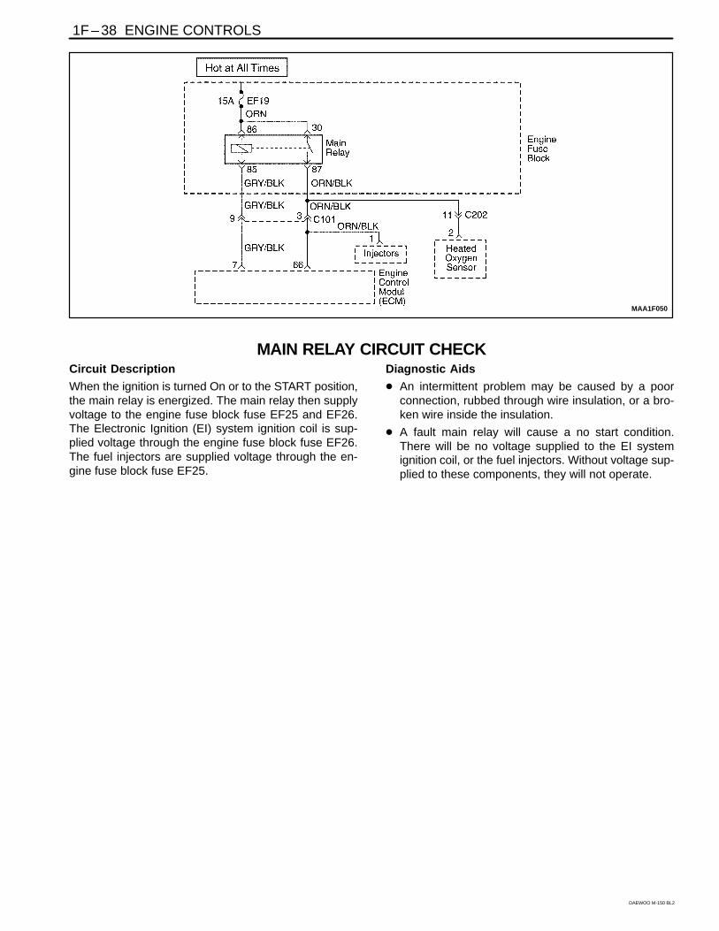
1F – 38 ENGINE CONTROLS
DAEWOO M-150 BL2
MAA1F050
MAIN RELAY CIRCUIT CHECKCircuit Description
When the ignition is turned On or to the START position,the main relay is energized. The main relay then supplyvoltage to the engine fuse block fuse EF25 and EF26.The Electronic Ignition (EI) system ignition coil is sup-plied voltage through the engine fuse block fuse EF26.The fuel injectors are supplied voltage through the en-gine fuse block fuse EF25.
Diagnostic Aids
An intermittent problem may be caused by a poorconnection, rubbed through wire insulation, or a bro-ken wire inside the insulation.
A fault main relay will cause a no start condition.There will be no voltage supplied to the EI systemignition coil, or the fuel injectors. Without voltage sup-plied to these components, they will not operate.

ENGINE CONTROLS 1F – 39
DAEWOO M-150 BL2
Main Relay Circuit Check
Step Action Value(s) Yes No
1
1. Turn the ignition OFF.2. Disconnect the engine fuse block fuse EF26.3. Turn the ignition ON.4. With a test light connected to the ground, probe
the fuse terminals nearest the main relay for fuseEF19.
Is the light on at both terminal?
–
System OK Go to Step 2
2 Is the light on at only one terminal? – Go to Step 3 Go to Step 4
3Repair the open in the wiring between the main relayconnector terminal 30 and the fuse EF19 as needed.Is the repair complete?
–System OK
–
4
1. Turn the ignition OFF.2. Remove the main relay.3. Turn the ignition ON.4. With a test light connected to the ground, probe
the main relay terminals 85 and 30.Is the light on at both terminals.
–
Go to Step 8 Go to Step 5
51. Turn the ignition OFF.2. Check engine fuse block fuse EF19.Is one or both fuse blown?
–Go to Step 6 Go to Step 7
6
1. Repair short circuit between terminal 87 of mainrelay and heated oxygen sensor
2. Replace fuse EF19.Is the repair complete?
–
System OK
–
7Repair open circuit between terminal 30 of mainrelay and fuse EF19.Is the repair complete?
–System OK Go to Step 8
8
1. Turn the ignition OFF.2. Measure the resistance between following
terminals. Terminal 86 of main relay and ground. Terminal 87 of main relay and ground.
Is the resistance within the specified value 0 Ω Go to Step 10 Go to Step 9
9Repair open circuit.Is the repair complete?
–System OK
–
10Replace the main relay.Is the repair complete?
–System OK
–

1F – 40 ENGINE CONTROLS
DAEWOO M-150 BL2
MAA1F060
MANIFOLD ABSOLUTE PRESSURE CHECKCircuit Description
The Manifold Absolute Pressure (MAP) sensor measurethe changes in the intake manifold pressure which resultfrom engine load (intake manifold vacuum) and rpmchanges. The MAP sensor converts these changes intovoltage output. The Engine Control Module (ECM) senda 5-volt reference voltage to the MAP sensor. As the in-take manifold pressure changes, the output voltage of
MAP sensor also changes. A low voltage (high vacuum)output of 1 to 1.5 volts is present at idle. A high voltage(low vacuum) output of 4.5 to 5.0 volts is present at wideopen throttle. The MAP sensor is also used under cer-tain conditions to measure barometric attitude changes.The ECM uses the MAP sensor for the delivery and igni-tion timing changes.

ENGINE CONTROLS 1F – 41
DAEWOO M-150 BL2
Manifold Absolute Pressure Check
Step Action Value(s) Yes No
1
1. Turn the ignition OFF.2. Connect a scan tool to the Data Link Connector
(DLC).3. Turn the ignition ON.4. Compare the Manifold Absolute Pressure (MAP)
sensor voltage reading from scanner with thatfrom known good vehicle.
Is the difference in the two voltage reading less thanthe value specified? 0.4 V Go to Step 2 Go to Step 5
2
1. Turn the ignition OFF.2. Connect a scan tool to the DLC.3. Disconnect the MAP sensor vacuum line.4. Connect a hand vacuum pump to the Map sensor.5. Turn the ignition ON.6. Note the MAP sensor voltage.7. Apply 34kPa (10 in. Hg) of vacuum to the Map
sensor and note the voltage change.Is the difference in voltage readings more than thevalue specified? 1.5 V System OK Go to Step 3
3Inspect the MAP sensor connector terminals.Is the problem found.
–Go to Step 4 Go to Step 5
4Repair the MAP sensor connector terminals asneeded.Is the repair complete?
–System OK
–
5Replace the MAP sensor.Is the repair complete?
–System OK
–
1F – 42 ENGINE CONTROLS
DAEWOO M-150 BL2
MAA1F070
IDLE AIR CONTROL SYSTEM CHECKCircuit Description
The Engine Control Module (ECM) controls the engineidle speed with the Idle Air Control (IAC) valve. To in-crease the idle speed, the ECM pulls the IAC pintleaway from its seat, allowing more air to pass by thethrottle body. To decrease the idle speed, it extends theIAC valve pintle toward its seat, reducing bypass airflow. A scan tool will read the ECM commands to theIAC valve in counts. The higher counts indicate more airbypass (higher idle). The lower counts indicate less air isallowed to bypass (lower idle).
Diagnostic Aids
If the idle is too high, stop the engine. Fully extend theIdle Air Control (IAC) valve with a IAC driver. Start theengine. If the idle speed is above 950 rpm, locate andrepair the vacuum leak. Also, check for a binding throttleplate or throttle linkage or an incorrect base idle setting.
Idle Air Control Valve Reset Procedure
Whenever the battery cable or the Engine Control Mod-ule (ECM) connector or the ECM fuse EF6 is discon-
nected or replaced, the following idle learn proceduremust be performed:
1. Turn the ignition ON for 5 seconds.
2. Turn the ignition OFF for 10 seconds.
3. Turn the ignition ON for 5 seconds.
4. Start the engine in park/neutral.
5. Allow the engine to run until the engine coolant isabove 85C (185F ).
6. Turn the A/C ON for 10 seconds, if equipped.
7. Turn the A/C OFF for 10 seconds, if equipped.
8. If the vehicle is equipped with an automatic trans-axle, apply the parking brake. While pressing thebrake pedal, place the transaxle in D (drive).
9. Turn the A/C ON for 10 seconds, if equipped.
10. Turn the A/C OFF for 10 seconds, if equipped.
11. Turn the ignition OFF. The idle learn procedure iscomplete.

ENGINE CONTROLS 1F – 43
DAEWOO M-150 BL2
Idle Air Control System Check
Step Action Value(s) Yes No
1
Perform an Euro On-Board Diagnostic (EOBD)system check.Was the check performed?
–
Go to Step 2
Go to “EuroOn-BoardDiagnostic
System Check”
2
1. Turn the ignition OFF.2. Remove Idle Air Control (IAC) valve.3. Inspect the IAC passages for restrictions.Is the problem found?
–
Go to Step 3 Go to Step 4
3Clean the IAC passages.Is the repair complete?
–System OK
–
4
Measure the resistance between following terminalsof IAC valve. Terminal A and B Terminal C and DDoes the resistance equal to the value specified? 40–80 Ω Go to Step 6 Go to Step 5
5Replace the IAC valve.Is the repair complete?
–System OK
–
6
1. Disconnect the Engine control Module (ECM)connector.
2. Check for an open or short in the wires betweenfollowing terminals. Terminal A of IAC valve connector and terminal
70 of ECM connector Terminal B of IAC valve connector and terminal
71 of ECM connector Terminal C of IAC valve connector and terminal
42 of ECM connector Terminal D of IAC valve connector and terminal
72 of ECM connectorIs the problem found?
–
Go to Step 8 Go to Step 7
7Repair an open or short circuit as needed.Is the repair complete?
–System OK
–
8Inspect the IAC connector terminals and the ECMconnector terminals.Is the problem found?
–Go to Step 9 Go to Step 10
9Repair or replace the throttle body assembly and/orECM connector terminals as needed.Is the repair complete?
–System OK
–
10Replace the ECM.Is the repair complete?
–System OK
–

1F – 44 ENGINE CONTROLS
DAEWOO M-150 BL2
MAA1F080
IGN
ITIO
N S
YS
TEM
CH
EC
K

ENGINE CONTROLS 1F – 45
DAEWOO M-150 BL2
IGNITION SYSTEM CHECKCircuit Description
The Electronic Ignition (EI) system uses a waste sparkmethod of spark distribution. In this type of EI system,the Crankshaft Position (CKP) sensor is mounted to theoil pump near a slotted wheel that is a part of the crank-shaft pulley. The CKP sensor sends reference pulses tothe Engine Control Module (ECM). The ECM then trig-
gers the EI system ignition coil. Each cylinder is individu-al with coil per cylinder in sequence.
This leaves the remainder of the high voltage to be usedto fire the spark plug in the cylinder on its compressionstroke. Since the CKP sensor is in a fixed position, tim-ing adjustments are not possible or needed.
Ignition System CheckCaution: Use only electrically insulated pliers whenhandling ignition wires with the engine running toprevent an electrical shock.
Step Action Value(s) Yes No
1
1. Remove the spark plugs.2. Inspect for wet spark plugs, cracks, wear,
improper gap, burned electrodes, or heavydeposits.
3. Replace the spark plugs as needed.Is the repair complete?
–
System OK Go to Step 2
2Check for the presence of spark from all of theignition wires while cranking the engine.Is spark present from all of the ignition wires?
–System OK Go to Step 3
3
1. Measure the resistance of the ignition wires.2. Replace any ignition wire(s) with a resistance
above the value specified.3. Check for the presence of spark from all of the
ignition wires.Is spark present from all of the ignition wires? 30000 Ω System OK Go to Step 4
4 Is spark present from at least one of the ignitionwires, but not all of the ignition wires?
Go to Step 5 Go to Step 12
5
1. Turn the ignition OFF.2. Disconnect the Electronic Ignition (EI) system
ignition coil connector.3. While cranking the engine, measure the voltage
at the EI system ignition coil connector terminal 1.Does the voltage fluctuate within the valuesspecified? 0.2–2.0 V Go to Step 8 Go to Step 6
6
Check for an open in the wire from EI systemignition coil connector terminal 1 to the EngineControl Module (ECM) connector terminal 66.Is the problem found?
–
Go to Step 7 Go to Step 11
7
1. Repair the wiring as needed.2. Connect the EI system ignition coil connector.3. Check for the presence of spark from all of the
ignition wires.Is spark present from all of the ignition wires?
–
System OK
–
8
While cranking the engine, measure the voltage atthe EI system ignition coil connector terminal 2.Does the voltage fluctuate within the valuesspecified? 0.2–2.0 V Go to Step 10 Go to Step 9

1F – 46 ENGINE CONTROLS
DAEWOO M-150 BL2
Ignition System Check (Cont’d)
Step Action Value(s) Yes No
9
Check for an open in the wire from EI systemignition coil connector terminal 2 to the EngineControl Module (ECM) connector terminal 1.Is the problem found?
–
Go to Step 7 Go to Step 11
10
1. Replace the EI system ignition coil.2. Connect the EI system ignition coil connector.3. Check for the presence of spark from all of the
ignition wires.Is spark present from all of the ignition wires?
–
System OK
–
11
1. Replace the ECM.2. Connect the EI system ignition coil connector.3. Check for the presence of spark from all of the
ignition wires.Is spark present from all of the ignition wires?
–
System OK
–
12
1. Turn the ignition OFF.2. Disconnect the crankshaft position (CKP) sensor
connector.3. Measure the resistance between the CKP sensor
terminals 1 and 2.Is the resistance within the value specified?4. Measure the resistance between following
terminals. Terminals 1 and 3 of CKP sensor. Terminals 2 and 3 of CKP sensor.
Is the resistance within the value specified?
400–600 Ω
∞ Go to Step 14 Go to Step 13
13Replace the crankshaft position sensor.Is the repair complete?
–System OK
–
14
1. Turn the ignition ON.2. Measure the voltage between the CKP sensor
connector terminals 1 and 3.Is the voltage within the value specified? 0.95–1.10 V Go to Step 20 Go to Step 15
15Measure the voltage between the CKP sensorconnector terminal 1 and ground.Is the voltage within the value specified? 0.95–1.10 V Go to Step 18 Go to Step 16
16
Check the wire between the CKP sensor connectorterminal 1 and the ECM connector terminal 54 for anopen or short.Is the problem found?
–
Go to Step 17 Go to Step 10
17Repair the wire between the CKP sensor connectorterminal 1 and the ECM connector terminal 54.Is the repair complete?
–System OK
–
18Check the wire between the CKP sensor connectorterminal 3 and ground for an open or short.Is the problem found?
–Go to Step 19 Go to Step 11
19Repair the wire between the CKP sensor connectorterminal 3 and ground.Is the repair complete?
–System OK
–
20
1. Turn the ignition ON.2. Measure the voltage between the CKP sensor
connector terminals 2 and 3.Is the voltage within the value specified? 0.95–1.10 V Go to Step 24 Go to Step 21

ENGINE CONTROLS 1F – 47
DAEWOO M-150 BL2
Ignition System Check (Cont’d)
Step Action Value(s) Yes No
21Measure the voltage between the CKP sensorconnector terminal 2 and ground.Is the voltage within the value specified? 0.95–1.10 V Go to Step 18 Go to Step 22
22
Check the wire between the CKP sensor connectorterminal 2 and the ECM connector terminal 24 for anopen or short.Is the problem found?
–
Go to Step 23 Go to Step 11
23Repair the wire between the CKP sensor connectorterminal 2 and the ECM connector terminal 24.Is the repair complete?
–System OK
–
24
1. Turn the ignition OFF.2. Connect a test light between the EI system
ignition coil connector terminal 2 and ground.3. Turn the ignition ON.Is the test light on?
–
Go to Step 27 Go to Step 25
25
Check for an open in the wiring between the EIsystem ignition coil connector, terminal 1 and themain relay connector terminal 87.Is the problem found?
–
Go to Step 26
Go to “MainRelay Circuit
Check”
26
Repair the open in the wiring between the EI systemignition coil connector terminal 1 and the main relayconnector terminal 87.Is the repair complete?
–
System OK
–
27Check for a damage in the terminal of the EI systemignition coil connector and repair as needed.Is the repair complete?
–System OK
–

1F – 48 ENGINE CONTROLS
DAEWOO M-150 BL2
MAA1F090
ENGINE COOLING FAN CIRCUIT CHECKCircuit Description
The engine cooling fan circuit operates the cooling fan.The cooling fan is controlled by the engine control mod-ule (ECM) based on input from the coolant temperaturesensor (CTS) and the A/C ON/OFF. The ECM controlsthe low speed cooling fan operation by internally ground-ing the ECM connector terminal 39. This energizes thelow speed cooling fan relay and operates the cooling fanat low speed. The low speed cooling fan operation isachieved by the cooling fan resistor causing a drop inthe voltage supplied to the cooling fan. The ECM con-trols the high speed cooling fan operation by internallygrounding the ECM connector terminal 5. This ener-gizes the high speed cooling fan relay, bypassing the ra-diator fan resistor. This results in high speed cooling fanoperation.
Diagnostic Aids
If the owner complained of an overheating problem, itmust be determined if the complaint was due to an
actual boil over, or the engine coolant temperaturegauge indicated overheating. If the engine is over-heating and the cooling fans are on, the cooling sys-tem should be checked.
If the engine fuse block fuse EF15 become open(blown) immediately after installation, inspect for ashort to ground in the wiring of the appropriate circuit.If the fuse become open (blown) when the coolingfans are to be turned on by the Engine Control Mod-ule (ECM), suspect a faulty cooling fan motor.
The ECM will turn the cooling fan on at low speedwhen the coolant temperature is 93C (199F). TheECM will turn the cooling fans off when the coolanttemperature is 90C (194F).
The ECM will turn the cooling fans on at high speedwhen the coolant temperature is 100C (212F). TheECM will change the cooling fans from high speed tolow speed when the coolant temperature is 97C(207F).

ENGINE CONTROLS 1F – 49
DAEWOO M-150 BL2
Engine Cooling Fan Circuit Check
Step Action Value(s) Yes No
1
Perform an Euro On-Board Diagnostic (EOBD)System Check.Was the check performed?
–
Go to Step 2
Go to “EuroOn-BoardDiagnostic
System Check.
2
1. Check the fuses EF3 and EF10 in engine fuseblock.
2. Replace the fuse(s) as needed.Is the fuse(s) OK?
–
Go to Step 3
Go to“Diagnostic
Aids”
3
1. Turn the ignition OFF.2. Turn the A/C switch OFF. If equipped.3. Connect a scan tool to the Data Link Connector
(DLC).4. Start the engine.5. The main cooling fan should run at low speed
when the coolant temperature reaches 96C(205F).
Does the cooling fan run at low speed?
–
Go to Step 4 Go to Step 8
4The cooling fans should run at high speed when thecoolant temperature reaches 100C (212F).Do the cooling fans run at high speed?
–Go to Step 5 Go to Step 19
5
1. Turn the ignition OFF.2. Start the engine.3. Turn the A/C switch ON.Does the cooling fan runs at low speed?
–
Go to Step 7 Go to Step 6
6
1. Diagnose the A/C compressor clutch circuit.2. Repair the A/C compressor clutch circuit as
needed.Is the repair complete?
–
System OK
–
7
1. Turn the ignition OFF.2. Start the engine.3. Turn the A/C switch ON and raise the rpm.4. The cooling fan should run at high speed when
the high side A/C pressure reaches 2068 kPa(300 psi).
Do the cooling fans run at high speed?
–
System OK
–
8
1. Turn the ignition OFF.2. Disconnect the cooling fan connector.3. Turn the ignition ON.4. Connect a test light between terminal 1 of cooling
fan connector and ground.Is the test light on?
–
Go to Step 9 Go to Step 12
9Connect a test light between terminal 2 of coolingfan connector and battery positive.Is the test light on?
–Go to Step 11 Go to Step 10
10Repair open circuit between terminal 2 of cooling fanconnector and ground.Is the repair complete?
–System OK
–
11
Check for a damaged terminals in main cooling fanconnector and repair it or replace the main coolingfan.Is the repair complete?
–
System OK
–

1F – 50 ENGINE CONTROLS
DAEWOO M-150 BL2
Engine Cooling Fan Circuit Check (Cont’d)
Step Action Value(s) Yes No
12
1. Turn the ignition ON.2. Connect a test light between terminals 86 and 30
of low speed cooling fan relay and ground.Does the test light on for both case?
–
Go to Step 14 Go to Step 13
13
Repair power supply circuit. Fuse EF15 and terminal 30 of low speed cooling
fan relay.Is the repair complete?
–
System OK Go to Step 14
14
1. Turn the ignition OFF.2. Disconnect Engine Control Module (ECM)
connectors.3. Turn the ignition ON.4. Connect a jump wire between terminal 5 and
ground.Does the cooling fan run at low speed?
–
Go to Step 15 Go to Step 16
15Replace the ECM.Is the repair complete?
–System OK
–
16
1. Turn the ignition OFF.2. Measure the resistance between following
terminals: Terminal 85 of low speed cooling fan relay and
terminal 39 of ECM connector.Are the resistance within the value specified? 0 Ω Go to Step 18 Go to Step 17
17Repair open circuit.Is the repair complete?
–System OK
–
18Replace the low speed cooling fan relay.Is the repair complete?
–System OK
–

ENGINE CONTROLS 1F – 51
DAEWOO M-150 BL2
BLANK

1F – 52 ENGINE CONTROLS
DAEWOO M-150 BL2
MAA1F010
DATA LINK CONNECTOR DIAGNOSISCircuit Description
The provision for communicating with the Engine Con-trol Module (ECM) is the Data Link Connector (DLC). Itis located under the instrument panel. The DLC is usedto connect the scan tool. Battery power and ground issupplied for the scan tool through the DLC. The Key-word 2000 serial data circuit to the DLC allows the ECMto communicate with the scan tool. A Universal Asyn-chronous Receiver Transmitter (UART) serial data lineis used to communicate with the other modules such asthe Electronic Brake Control Module (EBCM), the Sup-plemental Inflatable Restraint (SIR) system. and the In-strument Panel Cluster.
Diagnostic Aids
Ensure that the correct application (model line, car year,etc.) has been selected on the scan tool. If communica-tion still cannot be established, try the scan tool on
another vehicle to ensure that the scan tool or cablesare not the cause of the condition.
An intermittent may be caused by a poor connection,rubbed through wire insulation, or a broken wire insidethe insulation.
Any circuitry that is suspected of causing an intermittentcomplaint should be thoroughly checked for the follow-ing conditions:
Backed-out terminals.
Improper mating of terminals.
Broken locks.
Improperly formed or damaged terminals.
Poor terminal-to-wiring connection.
Physical damage to the wiring harness.
Corrosion.

ENGINE CONTROLS 1F – 53
DAEWOO M-150 BL2
Data Link Connector Diagnosis
Step Action Value(s) Yes No
1
Perform an Euro On-Board Diagnostic (EOBD)System Check.Was the check performed?
–
Go to Step 2
Go to “EuroOn-BoardDiagnostic
System Check.
2With a test light connected to the ground, probe theData Link Connector (DLC) battery feed terminal 16.Is the test light on?
–Go to Step 4 Go to Step 3
3Repair an open or short to ground in the DLC batteryfeed circuit .Is the repair complete?
–Go to Step 4
–
4With a test light connected to the battery, probe theData Link Connector (DLC) ground terminal 4 and 5.Is the test light on?
–Go to Step 6 Go to Step 5
5Repair an open circuit .Is the repair complete?
–Go to Step 6
–
6
1. Turn the ignition OFF.2. Connect a scan tool to the Data Link Connector
(DLC).3. Turn the ignition ON.Does the scan tool power up?
–
Go to Step 8 Go to Step 7
7Check for damages in the terminal of DLC and scantool, and repair as needed.Is the repair complete?
–Go to Step 8
–
8Using a scan tool, request engine data of EngineControl Module (ECM).Does the scan tool display any data?
–Go to Step 12 Go to Step 9
9
Install the scan tool on another vehicle and check forproper operation.Does the scan tool work properly on a differentvehicle.
–
Go to Step 11 Go to Step 10
10The scan tool is malfunctioning.Refer to the scan tool’s manual for repair.Is the repair complete?
–Go to Step 12
–
11Repair communication circuit between ECM andDLC.Is the repair complete?
–Go to Step 12
–
12
1. Using a scan tool, clear the Diagnostic TroubleCodes(DTCs).
2. Attempt to start the engine.Does the engine and continue to run?
–
Go to Step 13 Go to Step 1
13
1. Allow the engine to idle until normal operationtemperature reached.
2. Check if any DTCs are set?Are any DTCs displayed that have not beendiagnosed?
–Go to applicable
DTC table System OK

1F – 54 ENGINE CONTROLS
DAEWOO M-150 BL2
FUEL INJECTOR BALANCE TESTA fuel injector tester is used to energize the injector for aprecise amount of time, thus spraying a measuredamount of fuel into the intake manifold. This causes a
drop in the fuel rail pressure that can be recorded andused to compare each of the fuel injectors. All of the fuelinjectors should have the same pressure drop.
Fuel Injector Balance Test Example
Cylinder 1 2 3
First Reading 380 kPa(55 psi)
380 kPa(55 psi)
380 kPa(55 psi)
Second Reading 215 kPa(31 psi)
201 kPa(29 psi)
230 kPa(33 psi)
Amount Of Drop 165 kPa(24 psi)
179 kPa(26 psi)
151 kPa(22 psi)
Average Range: 156-176 kPa(22.5-25.5 psi)
Injector OK Faulty Injector –Too Much
Pressure Drop
Faulty Injector –Too Little
Pressure Drop
Caution: The fuel system is under pressure. Toavoid fuel spillage and the risk of personal injury orfire, it is necessary to relieve the fuel system pres-sure before disconnecting the fuel lines.
Caution: Do not pinch or restrict fuel lines. Damageto the lines could cause a fuel leak, resulting in pos-sible fire or personal injury.
Notice: In order to prevent flooding of the engine, do notperform the Injector Balance Test more than once (in-cluding any retest on faulty fuel injectors) without run-ning the engine.
Test
Notice: An engine cool down period of 10 minutes isnecessary in order to avoid irregular readings due to hotsoak fuel boiling.
1. Connect the fuel pressure gauge carefully to avoidany fuel spillage.
2. The fuel pump should run about 2 seconds after theignition is turned to the ON position.
3. Insert a clear tube attached to the vent valve of thefuel pressure gauge into a suitable container.
4. Bleed the air from the fuel pressure gauge and hoseuntil all of the air is bled from the fuel pressure gauge.
5. The ignition switch must be in the OFF position atleast 10 seconds in order to complete the electroniccontrol module (ECM) shutdown cycle.
6. Turn the ignition ON in order to get the fuel pressureto its maximum level.
7. Allow the fuel pressure to stabilize and then recordthis initial pressure reading. Wait until there is nomovement of the needle on the fuel pressure gauge.
8. Follow the manufacturer’s instructions for the use ofthe adapter harness. Energize the fuel injector test-er once and note the fuel pressure drop at its lowestpoint. Record this second reading. Subtract it fromthe first reading to determine the amount of the fuelpressure drop.
9. Disconnect the fuel injector tester from the fuel in-jector.
10. After turning the ignition ON, in order to obtain maxi-mum pressure once again, make a connection atthe next fuel injector. Energize the fuel injector test-er and record the fuel pressure reading. Repeat thisprocedure for all the injectors.
11. Retest any of the fuel injectors that the pressuredrop exceeds the 10 kPa (1.5 psi) specification.
12. Replace any of the fuel injectors that fail the retest.
13. If the pressure drop of all of the fuel injectors is with-in 10 kPa (1.5 psi), then the fuel injectors are flowingnormally and no replacement should be necessary.
14. Reconnect the fuel injector harness and review thesymptom diagnostic tables.