engine lubrication & cooling systems - … lubrication & cooling systems section ... in the...
TRANSCRIPT

ENGINE LUBRICATION &COOLING SYSTEMS
SECTIONLCCONTENTS
KA24DE
ENGINE LUBRICATION SYSTEM..................................3Precautions ..................................................................3
SUPPLEMENTAL RESTRAINT SYSTEM (SRS)″AIR BAG″ AND ″SEAT BELT PRE-TENSIONER″.........3LIQUID GASKET APPLICATION PROCEDURE............3
Preparation ..................................................................4SPECIAL SERVICE TOOLS ........................................4
Lubrication Circuit ........................................................5Oil Pressure Check......................................................6Oil Pump......................................................................6
REMOVAL AND INSTALLATION.................................6REGULATOR VALVE INSPECTION ............................7OIL FILTER ...............................................................7OIL PUMP INSPECTION ............................................7
Service Data and Specifications (SDS).......................8OIL PRESSURE CHECK ............................................8REGULATOR VALVE .................................................8OIL PUMP.................................................................8
ENGINE COOLING SYSTEM..........................................9Precautions ..................................................................9
SUPPLEMENTAL RESTRAINT SYSTEM (SRS)″AIR BAG″ AND ″SEAT BELT PRE-TENSIONER″.........9LIQUID GASKET APPLICATION PROCEDURE............9
Preparation ................................................................10SPECIAL SERVICE TOOLS ......................................10
Cooling Circuit ...........................................................10System Check............................................................11
CHECKING COOLING SYSTEM HOSES...................11CHECKING RADIATOR............................................11CHECKING COOLING SYSTEM FOR LEAKS............11CHECKING RADIATOR CAP ....................................12
Water Pump...............................................................12REMOVAL...............................................................12INSPECTION...........................................................12INSTALLATION........................................................13
Thermostat.................................................................13REMOVAL...............................................................13INSPECTION...........................................................13INSTALLATION........................................................13
Radiator .....................................................................14REMOVAL AND INSTALLATION...............................14COMPONENTS .......................................................15INSPECTION...........................................................15
Cooling Fan (Crankshaft driven) ...............................16REMOVAL AND INSTALLATION...............................16INSPECTION...........................................................16
Refilling Engine Coolant ............................................16Overheating Cause Analysis .....................................17Service Data and Specifications (SDS).....................18
THERMOSTAT ........................................................18RADIATOR..............................................................18
VG33E AND VG33ER
ENGINE LUBRICATION SYSTEM................................19Precautions ................................................................19
SUPPLEMENTAL RESTRAINT SYSTEM (SRS)″AIR BAG″ AND ″SEAT BELT PRE-TENSIONER″.......19LIQUID GASKET APPLICATION PROCEDURE..........19
Preparation ................................................................20SPECIAL SERVICE TOOLS ......................................20
Lubrication Circuit ......................................................20Oil Pressure Check....................................................21Oil Pump....................................................................21
REMOVAL AND INSTALLATION...............................21DISASSEMBLY AND ASSEMBLY..............................22INSPECTION...........................................................23REGULATOR VALVE INSPECTION ..........................23OIL FILTER .............................................................23OIL FILTER BRACKET.............................................24
Service Data and Specifications (SDS).....................25OIL PRESSURE CHECK ..........................................25REGULATOR VALVE ...............................................25OIL PUMP...............................................................25
ENGINE COOLING SYSTEM........................................26Precautions ................................................................26
SUPPLEMENTAL RESTRAINT SYSTEM (SRS)″AIR BAG″ AND ″SEAT BELT PRE-TENSIONER″.......26LIQUID GASKET APPLICATION PROCEDURE..........26
Preparation ................................................................27
GI
MA
EM
EC
FE
CL
MT
AT
TF
PD
AX
SU
BR
ST
RS
BT
HA
SC
EL
IDX
SPECIAL SERVICE TOOLS ......................................27Cooling Circuit ...........................................................27System Check............................................................27
CHECKING COOLING SYSTEM HOSES...................27CHECKING RADIATOR CAP ....................................28CHECKING RADIATOR............................................28CHECKING COOLING SYSTEM FOR LEAKS............29
Water Pump...............................................................29REMOVAL...............................................................29INSPECTION...........................................................30INSTALLATION........................................................30
Thermostat.................................................................31REMOVAL...............................................................31INSPECTION...........................................................31INSTALLATION........................................................32
Radiator .....................................................................32REMOVAL AND INSTALLATION...............................32COMPONENTS .......................................................33INSPECTION...........................................................33
Cooling Fan (Crankshaft driven) ...............................34REMOVAL AND INSTALLATION...............................34INSPECTION...........................................................34
Refilling Engine Coolant ............................................35Overheating Cause Analysis .....................................35Service Data and Specifications (SDS).....................36
THERMOSTAT ........................................................36RADIATOR..............................................................36
CONTENTS (Cont’d)
LC-2

PrecautionsSUPPLEMENTAL RESTRAINT SYSTEM (SRS) “AIR BAG” AND “SEAT BELTPRE-TENSIONER”
NGLC0066
The Supplemental Restraint System such as “AIR BAG” and “SEAT BELT PRE-TENSIONER”, used along witha seat belt, helps to reduce the risk or severity of injury to the driver and front passenger for certain types ofcollision. The Supplemental Restraint System consists of driver air bag module (located in the center of thesteering wheel), front passenger air bag module (located on the instrument panel on passenger side), seatbelt pre-tensioners, a diagnosis sensor unit, crash zone sensor, seat belt buckle switches, warning lamp, wir-ing harness and spiral cable.Information necessary to service the system safely is included in the RS section of this Service Manual.WARNING:� To avoid rendering the SRS inoperative, which could increase the risk of personal injury or death
in the event of a collision which would result in air bag inflation, all maintenance should be per-formed by an authorized NISSAN dealer.
� Improper maintenance, including incorrect removal and installation of the SRS, can lead to per-sonal injury caused by unintentional activation of the system. For removal of Spiral Cable and AirBag Module, see the RS section.
� Do not use electrical test equipment on any circuit related to the SRS unless instructed to in thisService Manual. SRS wiring harnesses can be identified by yellow and/or orange harness connec-tors.
SEM164F
AEM080
LIQUID GASKET APPLICATION PROCEDURENGLC0067
1. Use a scraper to remove all traces of old liquid gasket frommating surfaces and grooves. Also, completely clean any oilfrom these areas.
2. Apply a continuous bead of liquid gasket to mating surfaces.(Use Genuine Silicone RTV or equivalent. Refer to GI-50, “Rec-ommended Chemical Products and Sealants”.)
� For oil pan, be sure liquid gasket diameter is 3.5 to 4.5 mm(0.138 to 0.177 in).
� For areas except oil pan, be sure liquid gasket diameter is 2.0to 3.0 mm (0.079 to 0.118 in).
3. Apply liquid gasket around the inner side of bolt holes (unlessotherwise specified).
4. Assembly should be done within 5 minutes after coating.5. Wait at least 30 minutes before refilling engine oil and engine
coolant.
GI
MA
EM
EC
FE
CL
MT
AT
TF
PD
AX
SU
BR
ST
RS
BT
HA
SC
EL
IDX
ENGINE LUBRICATION SYSTEM KA24DEPrecautions
LC-3

PreparationSPECIAL SERVICE TOOLS
=NGLC0068
The actual shapes of Kent-Moore tools may differ from those of special service tools illustrated here.
Tool number(Kent-Moore No.)Tool name
Description
(J34301-C)Oil pressure gauge set1: (J34301-1)Oil pressure gauge2: (J34301-2)Hoses3: (J34298)Adapter4: (J34282-1)Adapter5: (790-301-1230-A)60° adapter6: (J34301-15)Square socket AAT896
Measuring oil pressureMaximum measuring range:1,379 kPa (14 kg/cm2, 200 psi)
WS39930000( — )Tube presser
NT052
Pressing the tube of liquid gasket
KV10115801(J38956)Oil filter wrench
NT362
Removing and installing oil filter
ENGINE LUBRICATION SYSTEM KA24DEPreparation
LC-4

Lubrication CircuitNGLC0069
WLC030
1. Connecting rod2. Connecting rod bearing3. Main bearing4. Oil filter5. Oil strainer
6. Oil pump7. Oil pan8. Piston oil jet9. Timing chain tensioner
10. Idler sprocket11. Upper timing chain tensioner12. Exhaust camshaft13. Intake camshaft
GI
MA
EM
EC
FE
CL
MT
AT
TF
PD
AX
SU
BR
ST
RS
BT
HA
SC
EL
IDX
ENGINE LUBRICATION SYSTEM KA24DELubrication Circuit
LC-5

ALC059
Oil Pressure CheckNGLC0070
WARNING:� Be careful not to burn yourself, as the engine and oil may
be hot.� Put the shift lever in the Neutral “N” position.1. Check oil level.2. Remove oil pressure switch.3. Install pressure gauge.4. Start engine and warm it up to normal operating temperature.5. Check oil pressure with engine running under no-load.
Unit: kPa (kg/cm2, psi)
Engine speed Approximate discharge pressure
Idle speed More than 78 (0.8, 11)
3,000 rpm 412 - 481 (4.2 - 4.9, 60 - 70)
� If difference is extreme, check oil passage and oil pumpfor oil leaks.
6. Install oil pressure switch with sealant.: 12.25 – 17.15 N·m (1.3 – 1.7 kg-m, 9 – 12 ft-lb)
Oil PumpREMOVAL AND INSTALLATION
NGLC0071
SLC945-A
ENGINE LUBRICATION SYSTEM KA24DEOil Pressure Check
LC-6

ALC054
� Always replace with new oil seal and gasket.� When removing oil pump, turn crankshaft so that No. 1
piston is at TDC on its compression stroke.� When installing oil pump, apply engine oil to gears, then
align punch mark on drive spindle and oil hole on oilpump.
ALC058
REGULATOR VALVE INSPECTIONNGLC0072
1. Visually inspect components for wear and damage.2. Check oil pressure regulator valve sliding surface and valve
spring.3. Coat regulator valve with engine oil. Check that it falls
smoothly into the valve hole by its own weight.� Replace regulator valve set or oil pump assembly, if dam-
aged.
ALC124
OIL FILTERNGLC0073
The oil filter is a small, full-flow cartridge type and is provided witha relief valve.� Use Tool KV10115801 (J38956) for removing oil filter.
SLC026
SLC732
OIL PUMP INSPECTIONNGLC0074
Using a feeler gauge, check the following clearances.Standard clearance:
Unit: mm (in)
Rotor tip clearance 1 Less than 0.12 (0.0047)
Outer rotor to body clearance 2 0.15 - 0.21 (0.0059 - 0.0083)
Side clearance (with gasket) 3 0.04 - 0.100 (0.0016 - 0.0039)
� If the tip clearance (1) exceeds the limit, replace rotor set.� If body to rotor clearances (2, 3) exceed the limit, replace
oil pump assembly.
GI
MA
EM
EC
FE
CL
MT
AT
TF
PD
AX
SU
BR
ST
RS
BT
HA
SC
EL
IDX
ENGINE LUBRICATION SYSTEM KA24DEOil Pump (Cont’d)
LC-7
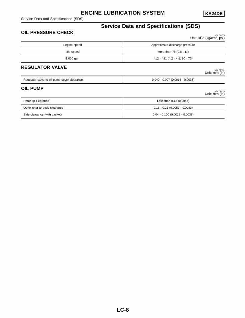
Service Data and Specifications (SDS)OIL PRESSURE CHECK
NGLC0075
Unit: kPa (kg/cm2, psi)
Engine speed Approximate discharge pressure
Idle speed More than 78 (0.8 , 11)
3,000 rpm 412 - 481 (4.2 - 4.9, 60 - 70)
REGULATOR VALVENGLC0131
Unit: mm (in)
Regulator valve to oil pump cover clearance 0.040 - 0.097 (0.0016 - 0.0038)
OIL PUMPNGLC0076
Unit: mm (in)
Rotor tip clearance Less than 0.12 (0.0047)
Outer rotor to body clearance 0.15 - 0.21 (0.0059 - 0.0083)
Side clearance (with gasket) 0.04 - 0.100 (0.0016 - 0.0039)
ENGINE LUBRICATION SYSTEM KA24DEService Data and Specifications (SDS)
LC-8

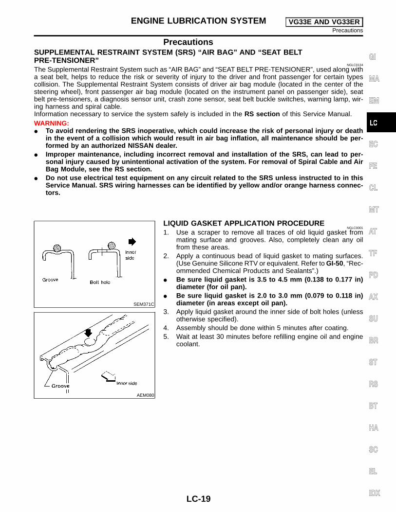
PrecautionsSUPPLEMENTAL RESTRAINT SYSTEM (SRS) “AIR BAG” AND “SEAT BELTPRE-TENSIONER”
NGLC0133
The Supplemental Restraint System such as “AIR BAG” and “SEAT BELT PRE-TENSIONER”, used along witha seat belt, helps to reduce the risk or severity of injury to the driver and front passenger for certain types ofcollision. The Supplemental Restraint System consists of driver air bag modules (located in the center of thesteering wheel), front passenger air bag module (located on the instrument panel on passenger side), seatbelt pre-tensioners, a diagnosis sensor unit, crash zone sensor, seat belt buckle switches, warning lamp, wir-ing harness and spiral cable.Information necessary to service the system safely is included in the RS section of this Service Manual.WARNING:� To avoid rendering the SRS inoperative, which could increase the risk of personal injury or death
in the event of a collision which would result in air bag inflation, all maintenance should be per-formed by an authorized NISSAN dealer.
� Improper maintenance, including incorrect removal and installation of the SRS, can lead to per-sonal injury caused by unintentional activation of the system. For removal of Spiral Cable and AirBag Module, see the RS section.
� Do not use electrical test equipment on any circuit related to the SRS unless instructed to in thisService Manual. SRS wiring harnesses can be identified by yellow and/or orange harness connec-tors.
SEM164F
AEM080
LIQUID GASKET APPLICATION PROCEDURENGLC0109
1. Use a scraper to remove all traces of old liquid gasket frommating surfaces and grooves. Also, completely clean any oilfrom these areas.
2. Apply a continuous bead of liquid gasket to mating surfaces.(Use Genuine Silicone RTV or equivalent. Refer to GI-50, “Rec-ommended Chemical Products and Sealants”.)
� For oil pan, be sure liquid gasket diameter is 3.5 to 4.5 mm(0.138 to 0.177 in).
� For areas except oil pan, be sure liquid gasket diameter is 2.0to 3.0 mm (0.079 to 0.118 in).
3. Apply liquid gasket around the inner side of bolt holes (unlessotherwise specified).
4. Assembly should be done within 5 minutes after coating.5. Wait at least 30 minutes before refilling engine oil and engine
coolant.
GI
MA
EM
EC
FE
CL
MT
AT
TF
PD
AX
SU
BR
ST
RS
BT
HA
SC
EL
IDX
ENGINE COOLING SYSTEM KA24DEPrecautions
LC-9

PreparationSPECIAL SERVICE TOOLS
=NGLC0110
The actual shapes of Kent-Moore tools may differ from those of special service tools illustrated here.
Tool number(Kent-Moore No.)Tool name
Description
EG17650301(J33984-A)Radiator cap testeradapter
NT564
Adapting radiator cap tester to radiator filler necka: 28 (1.10) dia.b: 31.4 (1.236) dia.c: 41.3 (1.626) dia.Unit: mm (in)
WS39930000( — )Tube presser
NT052
Pressing the tube of liquid gasket
Cooling CircuitNGLC0111
ALC117
ENGINE COOLING SYSTEM KA24DEPreparation
LC-10

System CheckNGLC0112
WARNING:� Never remove the radiator cap when the engine is hot.
Serious burns could occur from high pressure coolantescaping from the radiator.
� Wrap a thick cloth around the radiator cap. Slowly turn ita quarter turn to allow built-up pressure to escape. Care-fully remove the radiator cap by turning it all the way.
CHECKING COOLING SYSTEM HOSESNGLC0112S01
Check hoses for the following:� Improper attachment� Leaks� Cracks� Damage� Chafing� Deterioration
CHECKING RADIATORNGLC0112S02
Check radiator for mud or clogging. If necessary, clean radiator asfollows.CAUTION:� Be careful not to bend or damage the radiator fins.� When radiator is cleaned without removal, remove all sur-
rounding parts such as cooling fan, radiator shroud andhorns.
� Tape the harness connectors to prevent water from enter-ing.
1. Apply water by hose to the back side of the radiator core ver-tically downward.
2. Apply water again to all radiator core surfaces once perminute.
3. Stop washing when water coming out of the radiator flowsclear.
4. Blow air into the back side of radiator core vertically downward.� Use compressed air lower than 490 kPa (5 kg/cm2, 71 psi) and
keep the air hose end more than 30 cm (11.8 in) away.5. Blow air again into all the radiator core surfaces once per
minute until no water blows out and the core is dry.
SLC756A
CHECKING COOLING SYSTEM FOR LEAKSNGLC0112S03
To check for leakage, apply pressure to the cooling system with aradiator cap tester.
Testing pressure:157 kPa (1.6 kg/cm2, 23 psi)
CAUTION:Higher pressure than specified may cause radiator damage.
GI
MA
EM
EC
FE
CL
MT
AT
TF
PD
AX
SU
BR
ST
RS
BT
HA
SC
EL
IDX
ENGINE COOLING SYSTEM KA24DESystem Check
LC-11
SLC755A
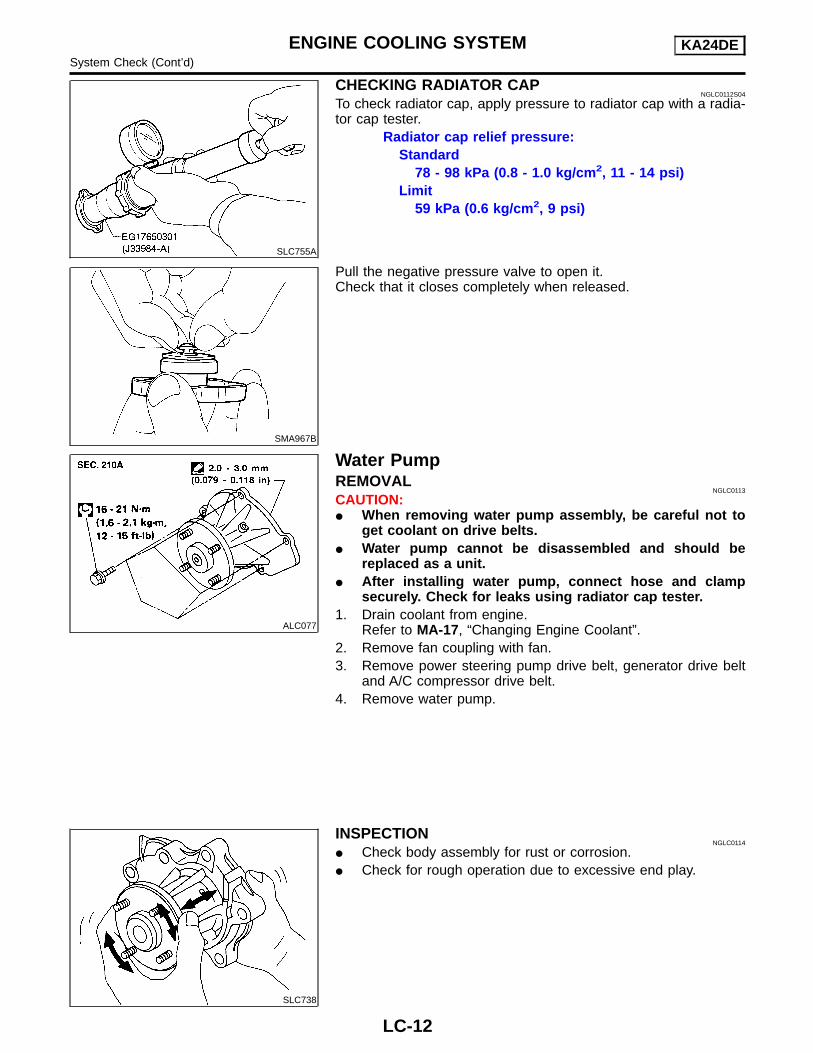
CHECKING RADIATOR CAPNGLC0112S04
To check radiator cap, apply pressure to radiator cap with a radia-tor cap tester.
Radiator cap relief pressure:Standard
78 - 98 kPa (0.8 - 1.0 kg/cm2, 11 - 14 psi)Limit
59 kPa (0.6 kg/cm2, 9 psi)
SMA967B
Pull the negative pressure valve to open it.Check that it closes completely when released.
ALC077
Water PumpREMOVAL
NGLC0113
CAUTION:� When removing water pump assembly, be careful not to
get coolant on drive belts.� Water pump cannot be disassembled and should be
replaced as a unit.� After installing water pump, connect hose and clamp
securely. Check for leaks using radiator cap tester.1. Drain coolant from engine.
Refer to MA-17, “Changing Engine Coolant”.2. Remove fan coupling with fan.3. Remove power steering pump drive belt, generator drive belt
and A/C compressor drive belt.4. Remove water pump.
SLC738
INSPECTIONNGLC0114
� Check body assembly for rust or corrosion.� Check for rough operation due to excessive end play.
ENGINE COOLING SYSTEM KA24DESystem Check (Cont’d)
LC-12

SLC188A
INSTALLATIONNGLC0115
1. Use a scraper to remove liquid gasket from water pump.� Also remove traces of liquid gasket from mating surface
of cylinder block.
ALC078
2. Apply a continuous bead of liquid gasket to mating surface ofwater pump.
� Use Genuine Silicone RTV or equivalent. Refer to GI-50,“Recommended Chemical Products and Sealants”.
When filling the radiator with coolant, refer to MA-17, “Chang-ing Engine Coolant”.When installing the drive belts, refer to MA-16, “Checking DriveBelts”.
ALC087
ThermostatREMOVAL
NGLC0116
� Be careful not to spill coolant over engine compartment.Use a rag to absorb coolant.
1. Drain coolant from engine. Refer to MA-17, “Changing EngineCoolant”.
2. Remove air cleaner and air duct assembly.3. Remove water hose from water inlet housing.4. Remove water inlet housing, then take out thermostat.
SLC343
INSPECTIONNGLC0117
1. Check valve seating condition at normal room temperature. Itshould seat tightly.
2. Check valve opening temperature and valve lift.
Valve opening temperature 76.5°C (170°F)
Valve lift More than 8 mm/90°C (0.31 in/194°F)
3. Check if valve closes at 5°C (9°F) below valve openingtemperature.
ALC088
INSTALLATIONNGLC0118
1. Use a scraper to remove old liquid gasket from water inlet.� Also remove traces of liquid gasket from mating surface
of front cover.2. Apply a continuous bead of liquid gasket to mating surface of
water inlet.� Use Genuine Silicone RTV or equivalent. Refer to GI-50,
“Recommended Chemical Products and Sealants”.
GI
MA
EM
EC
FE
CL
MT
AT
TF
PD
AX
SU
BR
ST
RS
BT
HA
SC
EL
IDX
ENGINE COOLING SYSTEM KA24DEWater Pump (Cont’d)
LC-13

SLC097
3. Install thermostat with jiggle valve or air bleeder at upper side.4. Install water inlet housing.5. Install water hose to water inlet housing.6. Install air cleaner and air duct assembly.7. Refill engine coolant. Refer to MA-17, “Changing Engine Cool-
ant”.� After installation, run engine for a few minutes and check
for leaks.
RadiatorREMOVAL AND INSTALLATION
NGLC0119
1. Remove under cover.2. Drain coolant from radiator. Refer to MA-17, “Changing Engine
Coolant”.3. Disconnect upper and lower radiator hoses.4. Remove air cleaner and air duct assembly.5. Remove lower radiator shroud.6. Remove radiator shroud.7. Disconnect coolant reservoir hose.8. Remove radiator.9. After replacing radiator, install all parts in reverse order of
removal.10. Refill engine coolant. Refer to MA-17, “Changing Engine Cool-
ant”.� After installation, run engine for a few minutes, and check
for leaks.
ENGINE COOLING SYSTEM KA24DEThermostat (Cont’d)
LC-14

COMPONENTSNGLC0120
WLC032
SLC933-A
INSPECTIONNGLC0130
1. Apply pressure with Tool.Specified pressure value:
157 kPa (1.6 kg/cm2, 23 psi)
SLC934
2. Check for leakage.
GI
MA
EM
EC
FE
CL
MT
AT
TF
PD
AX
SU
BR
ST
RS
BT
HA
SC
EL
IDX
ENGINE COOLING SYSTEM KA24DERadiator (Cont’d)
LC-15

ALC089
Cooling Fan (Crankshaft driven)REMOVAL AND INSTALLATION
NGLC0121
� Do not release the drive belt tension by removing the fan/waterpump pulley.
� Fan coupling cannot be disassembled and should be replacedas a unit. If front mark F is present, install fan so that sidemarked F faces the front.
� Install the drive belt only after the fan and fan coupling to waterpump flange bolts/nuts have been properly torqued.
� Proper alignment of these components is essential. Improperalignment will cause them to wobble and may eventually causethe fan to separate from the water pump, causing extensivedamage.
SLC072
INSPECTIONNGLC0122
Check fan coupling for rough operation, wobbling, oil leakage, orbent bimetal fins.
SLC151B
After assembly, verify the fan does not wobble or flap while theengine is running.WARNING:� When the engine is running, keep hands and clothing
away from moving parts such as drive belts and fan.
Refilling Engine CoolantNGLC0123
For details on refilling the engine cooling system, refer to MA-17,“REFILLING ENGINE COOLANT”.
ENGINE COOLING SYSTEM KA24DECooling Fan (Crankshaft driven)
LC-16

Overheating Cause Analysis=NGLC0125
Symptom Check items
Cooling sys-tem partsmalfunction
Poor heat transfer
Water pump malfunction Worn or loose drive belt
—
Thermostat stuck closed —
Damaged fins
Dust contamination orpaper clogging
Mechanical damage
Clogged radiator coolingtube
Excess foreign material(rust, dirt, sand, etc.)
Reduced air flow
Fan coupling does notoperate
Fan and coupling —High resistance to fan rota-tion
Damaged fan blades
Damaged radiator shroud — Fan shroud —
Improper coolant mixtureratio
—Coolant quality, viscosity
—
Poor coolant quality — —
Insufficient coolant
Coolant leaks
Cooling hoseLoose clamp
Cracked hose
Water pump Poor sealing
Radiator capLoose
Poor sealing
Radiator
O-ring for damage, deterio-ration or improper fitting
Cracked radiator tank
Cracked radiator core
Reservoir tank Cracked reservoir tank
Overflowing reservoir tankExhaust gas leaks intocooling system
Cylinder head deterioration
Cylinder head gasket dete-rioration
GI
MA
EM
EC
FE
CL
MT
AT
TF
PD
AX
SU
BR
ST
RS
BT
HA
SC
EL
IDX
ENGINE COOLING SYSTEM KA24DEOverheating Cause Analysis
LC-17

Symptom Check items
Except cool-ing systemparts mal-function
— Overload on engine
Abusive driving
Excessive payload
Driving in low gear forextended time
Driving at extremely highspeed
Powertrain system mal-function
—Installed improper sizewheels and tires
Dragging brakes
Improper ignition timing
Blocked or restricted airflow
Blocked bumper —
—
Blocked radiator grille
Installed car brassiere
Mud contamination orpaper clogging
Blocked radiator Dirty radiator
Blocked condenser Dirty condenser
Blockage in front of radia-tor
Installed large fog lamp
Service Data and Specifications (SDS)THERMOSTAT
NGLC0126
Valve opening temperature 76.5°C (170°F)
Valve lift More than 8 mm/90°C (0.31 in/194°F)
RADIATORNGLC0127
Unit: kPa (kg/cm2, psi)
Cap relief pressureStandard 78 - 98 (0.8 - 1.0, 11 - 14)
Limit 59 (0.6, 9)
Leakage test pressure 157 (1.6, 23)
ENGINE COOLING SYSTEM KA24DEOverheating Cause Analysis (Cont’d)
LC-18
PrecautionsSUPPLEMENTAL RESTRAINT SYSTEM (SRS) “AIR BAG” AND “SEAT BELTPRE-TENSIONER”
NGLC0134
The Supplemental Restraint System such as “AIR BAG” and “SEAT BELT PRE-TENSIONER”, used along witha seat belt, helps to reduce the risk or severity of injury to the driver and front passenger for certain typescollision. The Supplemental Restraint System consists of driver air bag module (located in the center of thesteering wheel), front passenger air bag module (located on the instrument panel on passenger side), seatbelt pre-tensioners, a diagnosis sensor unit, crash zone sensor, seat belt buckle switches, warning lamp, wir-ing harness and spiral cable.Information necessary to service the system safely is included in the RS section of this Service Manual.WARNING:� To avoid rendering the SRS inoperative, which could increase the risk of personal injury or death
in the event of a collision which would result in air bag inflation, all maintenance should be per-formed by an authorized NISSAN dealer.
� Improper maintenance, including incorrect removal and installation of the SRS, can lead to per-sonal injury caused by unintentional activation of the system. For removal of Spiral Cable and AirBag Module, see the RS section.
� Do not use electrical test equipment on any circuit related to the SRS unless instructed to in thisService Manual. SRS wiring harnesses can be identified by yellow and/or orange harness connec-tors.
SEM371C
AEM080
LIQUID GASKET APPLICATION PROCEDURENGLC0001
1. Use a scraper to remove all traces of old liquid gasket frommating surface and grooves. Also, completely clean any oilfrom these areas.
2. Apply a continuous bead of liquid gasket to mating surfaces.(Use Genuine Silicone RTV or equivalent. Refer to GI-50, “Rec-ommended Chemical Products and Sealants”.)
� Be sure liquid gasket is 3.5 to 4.5 mm (0.138 to 0.177 in)diameter (for oil pan).
� Be sure liquid gasket is 2.0 to 3.0 mm (0.079 to 0.118 in)diameter (in areas except oil pan).
3. Apply liquid gasket around the inner side of bolt holes (unlessotherwise specified).
4. Assembly should be done within 5 minutes after coating.5. Wait at least 30 minutes before refilling engine oil and engine
coolant.
GI
MA
EM
EC
FE
CL
MT
AT
TF
PD
AX
SU
BR
ST
RS
BT
HA
SC
EL
IDX
ENGINE LUBRICATION SYSTEM VG33E AND VG33ERPrecautions
LC-19

PreparationSPECIAL SERVICE TOOLS
=NGLC0002
The actual shapes of Kent-Moore tools may differ from those of special service tools illustrated here.
Tool number(Kent-Moore No.)Tool name
Description
ST25051001(J25695-1)Oil pressure gauge
NT558
Measuring oil pressureMaximum measuring range:2,452 kPa (25 kg/cm2, 356 psi)
ST25052000(J25695-2)Hose
NT559
Adapting oil pressure gauge to cylinder block
KV10115801(J38956)Oil filter wrench
NT362
Removing and installing oil filter
WS39930000( — )Tube presser
NT052
Pressing the tube of liquid gasket
Lubrication CircuitNGLC0003
SLC082B
ENGINE LUBRICATION SYSTEM VG33E AND VG33ERPreparation
LC-20

ALC120
Oil Pressure CheckNGLC0004
WARNING:� Be careful not to burn yourself, as the engine and oil may
be hot.� Put the shift lever in the Neutral “N” position.1. Check oil level.2. Remove oil pressure switch.
SLC926
3. Install pressure gauge.4. Start engine and warm it up to normal operating temperature.5. Check oil pressure with engine running under no-load.
Unit: kPa (kg/cm2, psi)
Engine speed Approximate discharge pressure
Idle speed More than 59 (0.6, 9)
2,000 rpm412 - 451 (4.2 - 4.6,
60 - 65)
If difference is extreme, check oil passage and oil pump for oilleaks.6. Install oil pressure switch with sealant.
: 12.25 – 17.15 N·m (1.3 – 1.7 kg-m, 9 – 12 ft-lb)
Oil PumpREMOVAL AND INSTALLATION
NGLC0005
1. Drain engine oil.2. Drain engine coolant from drain plug on radiator.3. Remove air duct from mass air flow sensor to throttle body.4. Remove cooling fan.5. Remove radiator hoses (upper and lower) and fan shroud.
Refer to “Radiator”, LC-32.6. Remove drive belts. Refer to MA-26, “Checking Drive Belts”.7. Remove crankshaft pulley and front upper and lower belt cov-
ers. Refer to EM-82, “TIMING BELT”.8. Remove oil pan. Refer to EM-79, “ OIL PAN”.9. Remove oil strainer.10. Remove oil pump assembly.
GI
MA
EM
EC
FE
CL
MT
AT
TF
PD
AX
SU
BR
ST
RS
BT
HA
SC
EL
IDX
ENGINE LUBRICATION SYSTEM VG33E AND VG33EROil Pressure Check
LC-21
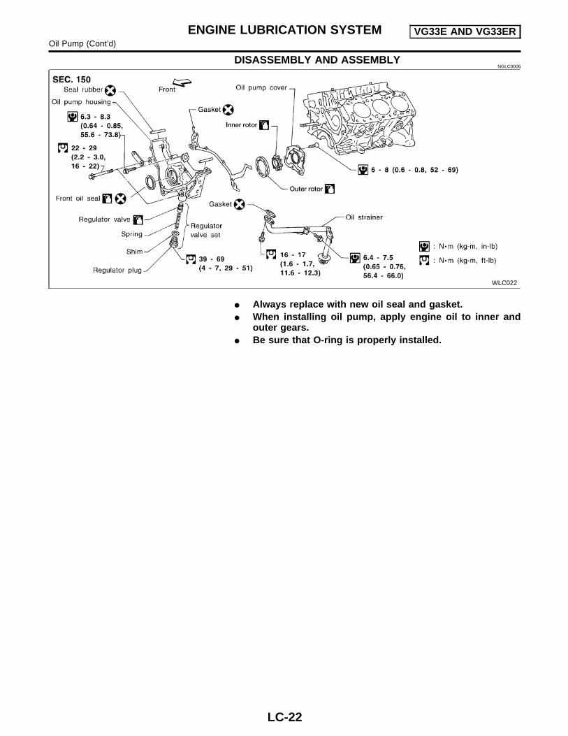
DISASSEMBLY AND ASSEMBLYNGLC0006
WLC022
� Always replace with new oil seal and gasket.� When installing oil pump, apply engine oil to inner and
outer gears.� Be sure that O-ring is properly installed.
ENGINE LUBRICATION SYSTEM VG33E AND VG33EROil Pump (Cont’d)
LC-22

SLC072B
SLC073B
WLC020
INSPECTIONNGLC0007
Using a feeler gauge, straightedge and micrometers, check thefollowing clearances:
Unit: mm (in)
Body to outer rotor radial clearance 1 0.114 - 0.200 (0.0045 - 0.0079)
Inner rotor to outer rotor tip clearance2
Below 0.18 (0.0071)
Body to inner rotor axial clearance 3 0.05 - 0.09 (0.0020 - 0.0035)
Body to outer rotor axial clearance 4 0.050 - 0.110 (0.0020 - 0.0043)
Inner rotor to brazed portion of hous-ing clearance 5
0.045 - 0.091 (0.0018 - 0.0036)
� If the tip clearance (2) exceeds the limit, replace rotor set.� If body to rotor clearances (1, 3, 4, 5) exceed the limit,
replace oil pump body assembly.
SLC074B
REGULATOR VALVE INSPECTIONNGLC0008
1. Visually inspect components for wear and damage.2. Check oil pressure regulator valve sliding surface and valve
spring.3. Coat regulator valve with engine oil. Check that it falls
smoothly into the valve hole by its own weight.If damaged, replace regulator valve set or oil pump assembly.
SLC035B
OIL FILTERNGLC0009
The oil filter is a small, full-flow cartridge type and is provided witha relief valve.� Use Tool KV10115801 (J38956) for removing oil filter.
GI
MA
EM
EC
FE
CL
MT
AT
TF
PD
AX
SU
BR
ST
RS
BT
HA
SC
EL
IDX
ENGINE LUBRICATION SYSTEM VG33E AND VG33EROil Pump (Cont’d)
LC-23

ALC121
OIL FILTER BRACKETNGLC0010
1. Remove oil filter.2. Disconnect oil pressure switch and connector.3. Remove oil filter bracket.
ENGINE LUBRICATION SYSTEM VG33E AND VG33EROil Pump (Cont’d)
LC-24

Service Data and Specifications (SDS)OIL PRESSURE CHECK
=NGLC0011
Unit: kPa (kg/cm2, psi)
Engine speed Approximate discharge pressure
Idle speed More than 59 (0.6, 9)
2,000 rpm 412 - 451 (4.2 - 4.6, 60 - 65)
REGULATOR VALVENGLC0012
Unit: mm (in)
Regulator valve to oil pump cover clearance 0.040 - 0.097 (0.0016 - 0.0038)
OIL PUMPNGLC0013
Unit: mm (in)
Body to outer rotor radial clearance 0.114 - 0.200 (0.0045 - 0.0079)
Inner rotor to outer rotor tip clearance Below 0.18 (0.0071)
Body to inner rotor axial clearance 0.05 - 0.09 (0.0020 - 0.0035)
Body to outer rotor axial clearance 0.050 - 0.110 (0.0020 - 0.0043)
Inner rotor to brazed portion of housing clearance 0.045 - 0.091 (0.0018 - 0.0036)
GI
MA
EM
EC
FE
CL
MT
AT
TF
PD
AX
SU
BR
ST
RS
BT
HA
SC
EL
IDX
ENGINE LUBRICATION SYSTEM VG33E AND VG33ERService Data and Specifications (SDS)
LC-25

PrecautionsSUPPLEMENTAL RESTRAINT SYSTEM (SRS) “AIR BAG” AND “SEAT BELTPRE-TENSIONER”
NGLC0135
The Supplemental Restraint System such as “AIR BAG” and “SEAT BELT PRE-TENSIONER”, used along witha seat belt, helps to reduce the risk or severity of injury to the driver and front passenger for certain typescollision. The Supplemental Restraint System consists of driver air bag module (located in the center of thesteering wheel), front passenger air bag module (located on the instrument panel on passenger side), seatbelt pre-tensioners, a diagnosis sensor unit, crash zone sensor, seat belt buckle switches, warning lamp, wir-ing harness and spiral cable.Information necessary to service the system safely is included in the RS section of this Service Manual.WARNING:� To avoid rendering the SRS inoperative, which could increase the risk of personal injury or death
in the event of a collision which would result in air bag inflation, all maintenance should be per-formed by an authorized NISSAN dealer.
� Improper maintenance, including incorrect removal and installation of the SRS, can lead to per-sonal injury caused by unintentional activation of the system. For removal of Spiral Cable and AirBag Module, see the RS section.
� Do not use electrical test equipment on any circuit related to the SRS unless instructed to in thisService Manual. SRS wiring harnesses can be identified by yellow and/or orange harness connec-tors.
SEM371C
AEM080
LIQUID GASKET APPLICATION PROCEDURENGLC0014
1. Use a scraper to remove all traces of old liquid gasket frommating surface and grooves. Also, completely clean any oilfrom these areas.
2. Apply a continuous bead of liquid gasket to mating surfaces.(Use Genuine Silicone RTV or equivalent. Refer to GI-50, “Rec-ommended Chemical Products and Sealants”.)
� Be sure liquid gasket is 3.5 to 4.5 mm (0.138 to 0.177 in)dia. (for oil pan).
� Be sure liquid gasket is 2.0 to 3.0 mm (0.079 to 0.118 in)dia. (in areas except oil pan).
3. Apply liquid gasket around the inner side of bolt holes (unlessotherwise specified).
4. Assembly should be done within 5 minutes after coating.5. Wait at least 30 minutes before refilling engine oil and engine
coolant.
ENGINE COOLING SYSTEM VG33E AND VG33ERPrecautions
LC-26

PreparationSPECIAL SERVICE TOOLS
=NGLC0015
The actual shapes of Kent-Moore tools may differ from those of special service tools illustrated here.
Tool number(Kent-Moore No.)Tool name
Description
EG17650301(J33984-A)Radiator cap testeradapter
NT564
Adapting radiator cap tester to radiator fillernecka: 28 (1.10) dia.b: 31.4 (1.236) dia.c: 41.3 (1.626) dia.Unit: mm (in)
WS39930000( — )Tube presser
NT052
Pressing the tube of liquid gasket
Cooling CircuitNGLC0016
ALC122
System CheckNGLC0017
WARNING:Never remove the radiator cap when the engine is hot. Seriousburns could occur from high pressure coolant escaping fromthe radiator.Wrap a thick cloth around the cap. Slowly turn it a quarter turnto allow built-up pressure to escape. Carefully remove the capby turning it all the way.
CHECKING COOLING SYSTEM HOSESNGLC0017S01
Check hoses for improper attachment, leaks, cracks, damage,loose connections, chafing and deterioration.
GI
MA
EM
EC
FE
CL
MT
AT
TF
PD
AX
SU
BR
ST
RS
BT
HA
SC
EL
IDX
ENGINE COOLING SYSTEM VG33E AND VG33ERPreparation
LC-27

SLC755A
CHECKING RADIATOR CAPNGLC0017S02
To check radiator cap, apply pressure to cap with a tester.Radiator cap relief pressure:
Standard78 - 98 kPa (0.8 - 1.0 kg/cm2, 11 - 14 psi)
Limit59 kPa (0.6 kg/cm2, 9 psi)
SMA967B
Pull the negative pressure valve to open it.Check that it closes completely when released.
CHECKING RADIATORNGLC0017S04
Check radiator for mud or clogging. If necessary, clean radiator asfollows.CAUTION:� Be careful not to bend or damage the radiator fins.� When radiator is cleaned without removal, remove all sur-
rounding parts such as cooling fan, radiator shroud andhorns.
� Tape the harness connectors to prevent water from enter-ing.
1. Apply water by hose to the back side of the radiator core ver-tically downward.
2. Apply water again to all radiator core surfaces once perminute.
3. Stop washing when stains no longer flow out from the radia-tor.
4. Blow air into the back side of radiator core vertically downward� Use compressed air lower than 490 kPa (5 kg/cm2, 71 psi) and
keep the air hose end more than 30 cm (11.8 in) away from thecore.
5. Blow air again into all the radiator core surfaces once perminute until no water blows out and the core is dry.
ENGINE COOLING SYSTEM VG33E AND VG33ERSystem Check (Cont’d)
LC-28

SLC756A
CHECKING COOLING SYSTEM FOR LEAKSNGLC0017S03
To check for leakage, apply pressure to the cooling system with atester.
Testing pressure: 157 kPa (1.6 kg/cm2, 23 psi)CAUTION:Higher pressure than specified may cause radiator damage.
Water PumpREMOVAL
NGLC0018
SLC076B
CAUTION:� When removing water pump assembly, be careful not to
get coolant on timing belt.� Water pump cannot be disassembled and should be
replaced as a unit.� After installing water pump, connect hose and clamp
securely, then check for leaks using radiator cap tester.� To avoid deforming timing cover, make sure there is
adequate clearance between it and the hose clamp.
GI
MA
EM
EC
FE
CL
MT
AT
TF
PD
AX
SU
BR
ST
RS
BT
HA
SC
EL
IDX
ENGINE COOLING SYSTEM VG33E AND VG33ERSystem Check (Cont’d)
LC-29

SMA207CA
SMA208CA
1. Drain coolant from drain plugs on both sides of cylinder blockand radiator. Refer to MA-28, “Changing Engine Coolant”.
2. Remove radiator hoses (upper and lower) and fan shroud.Refer to “Radiator”.
3. Remove drive belts. Refer to MA-26, “Checking Drive Belts”.4. Remove water pump pulley.5. Remove crankshaft pulley and front (upper and lower) belt
cover. Refer to EM-82, “TIMING BELT”.6. Remove water pump.
ALC123
INSPECTIONNGLC0019
1. Check for badly rusted or corroded body assembly and vanes.2. Check for rough operation due to excessive end play.
SLC188A
INSTALLATIONNGLC0132
1. Use a scraper to remove liquid gasket from water pump.� Also remove traces of liquid gasket from mating surface
of cylinder block.
ENGINE COOLING SYSTEM VG33E AND VG33ERWater Pump (Cont’d)
LC-30

ALC078
2. Apply a continuous bead of liquid gasket to mating surface ofthe water pump.
� Use Genuine Silicone RTV or equivalent. Refer to GI-50,“Recommended Chemical Products and Sealants”.
When filling the radiator with coolant, refer to MA-28, “Chang-ing Engine Coolant”.When installing the drive belts, refer to MA-26, “Checking DriveBelts”.
ThermostatREMOVAL
NGLC0020
1. Drain engine coolant from drain plugs on radiator.2. Remove radiator hoses (upper and lower) and fan shroud.3. Remove drive belts.4. Remove pulley bracket.5. Remove water inlet and thermostat assembly.
SLC081B
INSPECTIONNGLC0021
1. Check valve seating condition at ordinary temperatures. Itshould seat tightly.
SLC343
2. Check valve opening temperature and valve lift.
Description VG33E VG33ER
Valve opening tempera-ture
82°C (180°F) 76.5°C (170°F)
Valve liftMore than 10 mm/95°C
(0.39 in/203°F)More than 10 mm/90°C
(0.39 in/194°F)
3. Then check if valve is closed at 5°C (9°F) below valve open-ing temperature.
GI
MA
EM
EC
FE
CL
MT
AT
TF
PD
AX
SU
BR
ST
RS
BT
HA
SC
EL
IDX
ENGINE COOLING SYSTEM VG33E AND VG33ERWater Pump (Cont’d)
LC-31

SLC077B
INSTALLATIONNGLC0022
1. Install thermostat with jiggle valve or air bleeder at upper side.
SLC078B
2. When installing water inlet apply liquid gasket as shown.� Use Genuine Silicone RTV or equivalent. Refer to GI-50,
“Recommended Chemical Products and Sealants”.� After installation, run engine for a few minutes, and check
for leaks.� Be careful not to spill coolant over engine compartment.
Use a rag to absorb coolant.
RadiatorREMOVAL AND INSTALLATION
NGLC0023
1. Remove under cover.2. Drain coolant from radiator drain plug.3. Remove air duct. (From mass air flow sensor to throttle body)4. Disconnect radiator upper and lower hoses.5. Remove A/T oil cooler hoses. (A/T model only)6. Remove radiator lower shroud.7. Disconnect reservoir tank hose.8. Remove radiator.9. After repairing or replacing radiator, install any part removed in
reverse order of removal.10. Refill the engine cooling system. Refer to MA-28, “Changing
Engine Coolant”.� After installation, run the engine until it reaches normal
operating temperature and check for leaks.
ENGINE COOLING SYSTEM VG33E AND VG33ERThermostat (Cont’d)
LC-32

COMPONENTSNGLC0024
WLC031
SLC933-A
INSPECTIONNGLC0028
1. Apply pressure with Tool.Specified pressure value:
157 kPa (1.6 kg/cm2, 23 psi)
SLC934
2. Check for leakage.
GI
MA
EM
EC
FE
CL
MT
AT
TF
PD
AX
SU
BR
ST
RS
BT
HA
SC
EL
IDX
ENGINE COOLING SYSTEM VG33E AND VG33ERRadiator (Cont’d)
LC-33

SLC066B
Cooling Fan (Crankshaft driven)REMOVAL AND INSTALLATION
NGLC0029
� Do not release the drive belt tension by removing the fan/waterpump pulley.
� Fan coupling cannot be disassembled and should be replacedas a unit. If front mark F is present, install fan so that sidemarked F faces the front.
� Install the drive belt only after the fan and fan coupling to waterpump flange bolts/nuts have been properly torqued.
� Proper alignment of these components is essential. Improperalignment will cause them to wobble and may eventually causethe fan to separate from the water pump causing extensivedamage.
SLC067B
INSPECTIONNGLC0030
Check fan coupling for rough operation, wobbling, oil leakage orbent bimetal fins.
SLC151B
After assembly, verify the fan does not wobble or flap while theengine is running.WARNING:� When the engine is running, keep hands and clothing
away from moving parts such as drive belts and fan.
ENGINE COOLING SYSTEM VG33E AND VG33ERCooling Fan (Crankshaft driven)
LC-34

Refilling Engine Coolant=NGLC0031
For details on refilling the engine cooling system, refer to MA-29,“REFILLING ENGINE COOLANT”.
Overheating Cause AnalysisNGLC0032
Symptom Check items
Cooling sys-tem partsmalfunction
Poor heat transfer
Water pump malfunction —
—
Thermostat stuck closed —
Damaged fins
Dust contamination orpaper clogging
Mechanical damage
Clogged radiator coolingtube
Excess foreign material(rust, dirt, sand, etc.)
Reduced air flow
Cooling fan does not oper-ate
Fan and coupling—
High resistance to fan rota-tion
Damaged fan blades
Damaged radiator shroud — Fan shroud
Improper coolant mixtureratio
—Coolant quality, viscosity
—
Poor coolant quality — —
Insufficient coolant
Coolant leaks
Cooling hoseLoose clamp
Cracked hose
Water pump Poor sealing
Radiator capLoose
Poor sealing
Radiator
O-ring for damage, deterio-ration or improper fitting
Cracked radiator tank
Cracked radiator core
Reservoir tank Cracked reservoir tank
Overflowing reservoir tankExhaust gas leaks intocooling system
Cylinder head deterioration
Cylinder head gasket dete-rioration
GI
MA
EM
EC
FE
CL
MT
AT
TF
PD
AX
SU
BR
ST
RS
BT
HA
SC
EL
IDX
ENGINE COOLING SYSTEM VG33E AND VG33ERRefilling Engine Coolant
LC-35
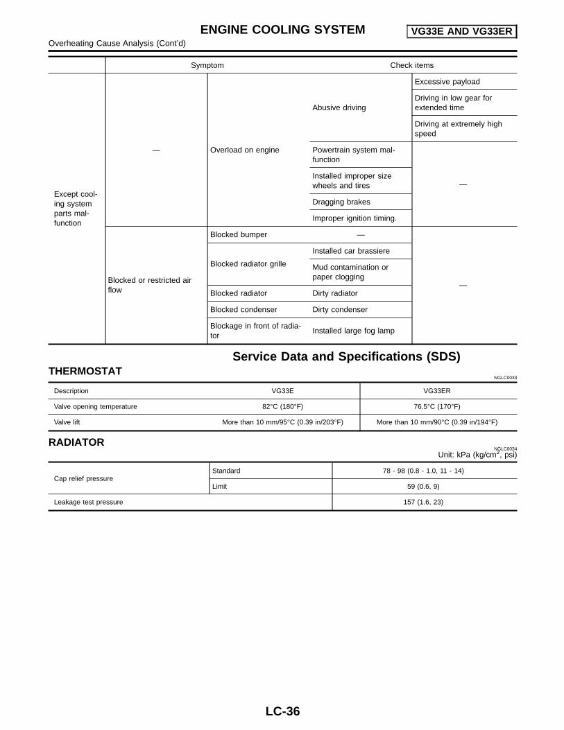
Symptom Check items
Except cool-ing systemparts mal-function
— Overload on engine
Abusive driving
Excessive payload
Driving in low gear forextended time
Driving at extremely highspeed
Powertrain system mal-function
—Installed improper sizewheels and tires
Dragging brakes
Improper ignition timing.
Blocked or restricted airflow
Blocked bumper —
—
Blocked radiator grille
Installed car brassiere
Mud contamination orpaper clogging
Blocked radiator Dirty radiator
Blocked condenser Dirty condenser
Blockage in front of radia-tor
Installed large fog lamp
Service Data and Specifications (SDS)THERMOSTAT
NGLC0033
Description VG33E VG33ER
Valve opening temperature 82°C (180°F) 76.5°C (170°F)
Valve lift More than 10 mm/95°C (0.39 in/203°F) More than 10 mm/90°C (0.39 in/194°F)
RADIATORNGLC0034
Unit: kPa (kg/cm2, psi)
Cap relief pressureStandard 78 - 98 (0.8 - 1.0, 11 - 14)
Limit 59 (0.6, 9)
Leakage test pressure 157 (1.6, 23)
ENGINE COOLING SYSTEM VG33E AND VG33EROverheating Cause Analysis (Cont’d)
LC-36