engineering & design standards - mesa, az
TRANSCRIPT

ENGINEERING PROCEDURE MANUAL
City of Mesa Engineering Department
Engineering & Design Standards

April 2019
C I T Y O F M E S A
Engineering & Design Standards
April 2019 City of Mesa
Development Services and Engineering Departments P.O. Box 1466
Mesa AZ 85211-1466

April 2019 i
Preface The Engineering & Design Standards provide specific direction and guidelines to design professionals preparing construction documents for private land development projects and/or city CIP projects. The construction documents and various reports (drainage, etc.) will be reviewed by the Engineering and Development Services Departments (Planning Section) for compliance with applicable codes, standards, stipulations, agreements and policies.
The format of the Engineering & Design Standards labels each paragraph so each may be clearly referenced as needed. A comprehensive Table of Contents and an Index are also provided. The “Engineering & Design Standards” volume is available on the City of Mesa Engineering Department’s webpage (http://mesaaz.gov/business/engineering ) as an electronic document.
Questions or comments regarding the contents of the Engineering & Design Standards should be directed to the Engineering Department at 480-644-2251.

April 2019 ii
Table of Contents PREFACE ....................................................................................... I TABLE OF CONTENTS .............................................................. II CHAPTER 1 - GENERAL REQUIREMENTS .......................... 1
Section 101 - Purpose & Intent ................................................ 1 Section 102 - Applicability of the Standards ........................... 1 Section 103 - Private Infrastructure Standards ....................... 1 Section 104 - Civil Engineering Standards ............................. 2 Section 105 - Construction Documents ................................... 2
Table 105.5.1: General Guidelines for Drawing Scales ...... 3 Section 106 - Dedications & Abandonments ......................... 10 Section 107 - Construction Phasing ...................................... 12 Section 108 - Public Utility .................................................... 12 Section 109 - Franchised Private Facilities .......................... 12 Section 110 - Non-Franchised Private Facilities .................. 13 Section 111 - Projects Involving Other Jurisdictions ............ 13 Section 112 - Preliminary Plan Review Services .................. 13 Section 113 - Processes & Procedures .................................. 14 Section 114 - Construction Document Submittals ................. 15 Section 115 - Scalloped Street Assessments .......................... 15 Section 116 - Development Agreements ................................ 16 Section 117 - Construction Document Compliance .............. 16 Section 118 - Reproducibles Submittal .................................. 17 Section 119 - Land Development Permits.............................. 17 Section 120 - Addenda ........................................................... 18 Section 121 - Project Construction ........................................ 18 Section 122 - Records............................................................. 19
Figure 1.1 – Construction Certification Letter – Public Improvements ..................................................................... 20 Figure 1.2 – Construction Certification Letter – Private Improvements ..................................................................... 21
CHAPTER 2 - PUBLIC STREET IMPROVEMENTS ........... 22 Section 201 - General Information ........................................ 22 Section 202 - Mesa Transportation Plan ............................... 22 Section 203 - City Code, Policies & Regulations .................. 23 Section 204 - Standards, Specifications and Guidelines ....... 23 Section 205 - Public Street Pavement .................................... 24 Section 206 - Half-Street Improvements ................................ 25 Section 207 - Street Widening ................................................ 26 Section 208 – Turn and Deceleration Lanes ......................... 26 Section 209 - Pavement Tapers .............................................. 27 Section 210 - Curb and Gutter ............................................... 28
Table 2.1 – Curb Returns and Ramp Types per Intersection ............................................................................................ 28
Section 211 - Sight Distance and Visibility ........................... 29 Section 212 - Raised Medians ................................................ 30 Section 213 - Traffic Signals .................................................. 32 Section 214 - Traffic Calming ................................................ 32 Section 215 - Public Alleys .................................................... 32 Section 216 - Pedestrian Facilities ........................................ 33 Section 217 – Transit Facilities ............................................. 35 Section 218 – Intersection Design ......................................... 35 Section 219 - Public Street Access ......................................... 37 Section 220 - Public Street Infrastructure Appurtenances .... 40
Figure 2.1 – Half Street Improvements ............................. 42 Figure 2.4 – Sight Distance Requirements for Stop Signs 45 Figure 2.5 – Traffic Signal and Median Spacing ............... 46 Figure 2.6 – School Bus Pullout ........................................ 47
CHAPTER 3 - PUBLIC UTILITIES - WATER ...................... 48 Section 301 - General Information ........................................ 48 Section 302 - Water Master Plan .......................................... 48 Section 303 - Availability of City of Mesa Water .................. 49 Section 304 - City Code, Policies & Regulations .................. 49 Section 305 - City Code ......................................................... 49 Section 306 - City Ordinances ............................................... 49 Section 307 - City Policy ....................................................... 49 Section 308 - Maricopa County Department of Environmental Services (MCESD) ................................................................. 50 Section 309 - Arizona Department of Environmental Quality (ADEQ) .................................................................................. 50 Section 310 - Arizona Department of Water Resources (ADWR) .................................................................................. 50 Section 311 - Public Water Supply & Distribution System Design .................................................................................... 50
Table 3.1 - Average Day Water Demands By Land Use* 51 Section 312 - Design Analysis ............................................... 52 Section 313 - Water Service Agreement ................................ 53 Section 314 - Other Water Service Providers ....................... 53 Section 315 - Design Standards, Specifications & Guidelines ................................................................................................ 54 Section 316 - Public Water Main Design .............................. 54 Section 317 - Water Appurtenances ...................................... 65
Table 3.2: Premise and Service Connections that Require an RP or AG ....................................................................... 74 Table 3.3: Fire Sprinkler Systems and Backflow Devices ............................................................................................ 75 Figure 3.1 – City of Mesa Water Service/Planning Area .. 77
CHAPTER 4 - PUBLIC UTILITIES - WASTEWATER ........ 78 Section 401 - General Information ........................................ 78 Section 402 - Wastewater Master Plans ................................ 79 Section 403 - Availability of City of Mesa Sewer .................. 79 Section 404 - City Code, Policies & Regulations .................. 79 Section 405 - City Code ......................................................... 79 Section 406 - City Ordinances ............................................... 79 Section 407 - City Policy ....................................................... 80 Section 408 - Maricopa County Environmental Services Department (MCESD) ........................................................... 80 Section 409 - Arizona Department of Environmental Quality (ADEQ) .................................................................................. 80 Section 410 - EPA Regulations .............................................. 80 Section 411 - Public Wastewater System Design .................. 81
Table 4.2 Commercial and Industrial Wastewater Flows . 81 Table 4.3 Peaking Factors .................................................. 81
Section 412 - Sewer Studies ................................................... 82 Section 413 - Sewer Service Agreement ................................ 82 Section 414 - Design Analysis ............................................... 82 Section 415 - Sewer Collection & Plant Capacity Adequacy 83 Section 416 - Standards, Specifications & Guidelines .......... 83 Section 417 - Private Sewer Utility Companies .................... 83 Section 418 - Sanitary Sewer Main Design ........................... 84 Section 419 - Velocity & Slopes............................................. 85 Section 420 - Sizing ................................................................ 85 Section 421 - Materials .......................................................... 86 Section 422 - Minimum Separations (Extra Protection) ....... 87 Section 423 - Intersecting Sewer Mains ................................ 87 Section 424 - Trench Crossings ............................................. 88
April 2019 iii
Section 425 - Main Stubs ....................................................... 88 Section 426 - Force Mains ..................................................... 88 Section 427 - Curvilinear Sewers .......................................... 89 Section 428 - Septic Systems .................................................. 89 Section 429 - Dry Sanitary Sewer Systems (Unconnected) ... 89 Section 430 - Structure Crossings.......................................... 89 Section 431 - Pipe Casings .................................................... 90 Section 432 - Private Sewer Lines ......................................... 90 Section 433 - Sanitary Sewer Appurtenances ........................ 90
Table 4.4 Manhole Spacing ............................................... 90 CHAPTER 5 - PUBLIC UTILITIES – NATURAL GAS ........ 93
Section 501 - General Information ........................................ 93 Section 502 - Availability of City of Mesa Natural Gas Service ................................................................................................ 94 Section 503 - City Code, Policies & Regulations .................. 94 Section 504 - Natural Gas System Design ............................. 94
Figure 5.1: Natural Gas Service Areas .............................. 96 CHAPTER 6 - PUBLIC UTILITIES – CITY ELECTRIC ..... 97
Section 601 - General Information ........................................ 97 Section 602 - City Code, Policies & Regulations .................. 97 Section 603 - City Policy ........................................................ 98 Section 604 - Electric Service Design .................................... 98
Figure 6.1 City of Mesa Electric Service Area ................ 100 CHAPTER 7 - PUBLIC UTILITIES – NON-CITY UTILITIES ................................................................................. 101
Section 701 - General Information ...................................... 101 Section 702 - Availability of Non-City Utilities ................... 102 Section 703 - City Code, Policies & Regulations ................ 102 Section 704 - City Ordinances ............................................. 102 Section 705 – City Policy ..................................................... 103 Section 706 - Design Standards, Specifications & Guidelines .............................................................................................. 104 Section 707 - Non-City Utility Construction Plans: ............ 107 Section 708 - Permit Application & Plan Submittal ............ 108 Section 709 - Plan Review, Approval & Permit Issuance ... 108 Section 710 - Permit Extensions .......................................... 109 Section 711 - Construction & Inspections ........................... 109
CHAPTER 8 - STORM WATER DRAINAGE & RETENTION .............................................................................. 110
Section 801 - General Information ...................................... 110 Section 802 - Storm Drain Master Plans ............................. 111 Section 803 - Availability of City of Mesa Storm Drain Systems ................................................................................. 111 Section 804 - City Code, Policies & Regulations ................ 111 Section 805 - City Code ....................................................... 112 Section 806 - On-Site Storm Water Management ................ 112
Table 8.1 - Developed Condition Runoff (C) Coefficients by Storm Frequency1 ........................................................ 113
Section 807 - Off-Site Storm Water Management................ 123 Table 8.2 Manhole Spacing ............................................. 125
Section 808 - Public versus Private Retention Basins ......... 130 Section 809 - Public Retention Basins ................................. 131 Section 810 - Construction Documents ............................... 133 Section 811 - Construction & Inspections ........................... 137 Section 812 - Flood Control District of Maricopa County (FCDMC) ............................................................................. 137 Section 813 - Maricopa County Air Quality Department (MCAQD) ............................................................................. 138 Section 814 - Arizona Department of Environmental Quality (ADEQ) ................................................................................. 138 Section 815 - Army Corps of Engineers (Corps) ................. 139
Figure 8.1 - Drywell Detail .............................................. 140 Figure 8.2 – Redevelopment Area ................................... 141
CHAPTER 9 - PUBLIC STREET LIGHTING REQUIREMENTS ..................................................................... 142
Section 901 - General Information ...................................... 142 Section 902 - City Code, Policies & Regulations ................ 142 Section 903 - City Code ....................................................... 143 Section 904 - City Policy ..................................................... 143 Section 905 - Arizona State Statutes .................................... 143 Section 906 - Public Street Lighting System Design ........... 143
Table 9.1 Street Classifications ....................................... 144 Section 907 - Lighting Analysis ........................................... 145 Section 908 - Design Standards, Specifications & Guidelines .............................................................................................. 145 Section 909 - Circuits, Wire & Conductors ......................... 148 Section 910 - Point Of Service (POS) .................................. 150 Section 911 - Power Supply ................................................. 150 Section 912 - Voltage Drop ................................................. 150 Section 913 - Photometrics .................................................. 150 Section 914 - Location ......................................................... 150 Section 915 - Clearances ..................................................... 151 Section 916 - Public Street Crossings ................................. 152 Section 917 - Desert Uplands .............................................. 152 Section 918 - Public Street Lighting Components ............... 153 Section 919 - Improvement Plans - Public Street Lighting . 154
CHAPTER 10 – SOLID WASTE MANAGEMENT REQUIREMENTS ..................................................................... 156
Section 1001 - General Information .................................... 156 Section 1002 - Code, Policies & Regulations ..................... 157 Section 1003 - General Requirements ................................. 157 Section 1004 - Solid Waste Design Requirements ............... 157
CHAPTER 11 – LANDSCAPING AND IRRIGATION REQUIREMENTS ..................................................................... 159
Section 1101 - General Information .................................... 159

E N G I N E E R I N G & D E S I G N S T A N D A R D S
April 2019
Chapter 1 - General Requirements This chapter presents the minimum criteria & standards to prepare construction documents for private land development and city projects within the jurisdiction of the City of Mesa.
his Engineering & Design Standards manual is intended to provide guidance and direction to the development and engineering community engaged in land development within the corporate limits of Mesa and/or within the City’s Utility Service Area or Planning Area (collectively referred to as the City of Mesa’s jurisdictional area).
Section 101 - Purpose & Intent 101.1 The purpose of the Engineering & Design Standards is to provide both general information and specific design standards to the design professionals who are preparing development construction documents that include or involve the installation or construction of public infrastructure for the City of Mesa. The intent of the Engineering & Design Standards is to provide developers, consultants and contractors information on Mesa’s standards and design criteria.
Section 102 - Applicability of the Standards 102.1 The Engineering & Design Standards are applicable to projects constructing public infrastructure (i.e., public water, sewer, storm drain, natural gas or electric utilities owned, operated or maintained by the City of Mesa; public streets and facilities; public retention basins & drainage facilities; public street lighting & signalization; or private facilities installed by a Public Utility or Franchisee, etc.) within dedicated public right-of-way or easements.
102.2 These standards also apply to drainage, retention and solid waste management requirements for private facilities.
Section 103 - Private Infrastructure Standards 103.1 Developers of projects involving private infrastructure may incorporate the City’s standards into their project design if they choose to; however, the City of Mesa will not accept responsibility for the
Chapter
1
T
E N G I N E E R I N G & D E S I G N S T A N D A R D S G E N E R A L R E Q U I R E M E N T S
April 2019 2
design, construction, or maintenance of private facilities or infrastructure. Developers and their design teams are also reminded that private structures and infrastructure are subject to the adopted Codes (Building, Fire, Electrical, etc.)
Section 104 - Civil Engineering Standards 104.1 The City of Mesa has adopted the following engineering standards for the construction of public infrastructure. All land development projects within the jurisdiction of the City of Mesa are required to utilize the following adopted standards:
104.2 The “Uniform Standard Specifications for Public Works Construction” and the associated “Uniform Standard Details for Public Works Construction” as published by Maricopa Association of Governments (M.A.G.) and as amended by the City of Mesa. Copies of the M.A.G. Standards, which are updated annually, are available on the internet at http://www.azmag.gov/Newsroom/Publications.
104.3 As noted, the City’s adoption of the M.A.G. standards is with local modification. The City’s modification to the M.A.G. standards is known as the “Mesa Standard Details & Specifications – Amendment to M.A.G. Uniform Standard Details & Specifications for Public Works Construction.” The development and maintenance of the amendments is the responsibility of the Engineering Department. Generally, the amendments are updated on an annual basis. The amendment to the M.A.G. standards is available on the Engineering Department webpage at: http://mesaaz.gov/business/engineering/mesa-standard-details-specifications
104.4 Construction shall be per the Mesa standard details applicable at the time of the right-of-way permit is issued (for private development) or on the bid date (for City-funded projects).
104.5 Engineers, architects and designers (hereafter referred to as “designer” or “designers”, which is understood to include the other terms) are encouraged to provide design solutions that will meet or exceed the minimum standards adopted by the City of Mesa.
104.6 Infrastructure constructed adjacent to existing and future light rail alignments shall follow the Valley Metro Design Criteria Manual available on the internet at http://www.valleymetro.org/images/uploads/lightrail_publications/design-criteria-manual_FINAL_May-2010.pdf
104.7 The City of Mesa has published a Low Impact Development Toolkit, available on the internet at http://www.mesaaz.gov/home/showdocument?id=14999 . The Toolkit is a guideline for the use of sustainable stormwater management tools. Designers are encouraged to employ sustainable stormwater management methods where appropriate and compliant with City Code and adopted development standards. Tools presented in the toolkit are conceptual; the details of their application must be reviewed and approved on a per project basis.
Section 105 - Construction Documents 105.1 Proposed Projects: Private land development projects involving the construction of public works infrastructure improvements (public streets, facilities or utilities) are required to submit construction documents and any necessary or supporting reports to the City’s Development Services Department

E N G I N E E R I N G & D E S I G N S T A N D A R D S G E N E R A L R E Q U I R E M E N T S
April 2019 3
(DSD) permit counter for code review and permitting. These construction documents are to be developed per the following standards.
105.2 Document Size: All civil engineering improvement plans submitted shall be in PDF format on 24" x 36" sheets with a minimum 2" left border and 0.5" on all other sides when reproduced at actual size. Larger size submittal, if allowed, will be charged a premium fee.
105.3 Reports: All supporting or supplemental reports are to be PDF documents with letter-sized (8.5" x 11") pages. Larger exhibits or maps shall be provided in PDF at their full size, generated from the original drawing files. Occasionally, printed copies may be required. If printed copies are required any larger maps included within the reports are to be folded to letter size and bound or provided in a folder or pocket bound with the report. Digital/electronic files of the project’s drainage, soils investigation reports and other supporting or supplemental reports shall be submitted to the Development Services Department prior to the issuance of the permit.
105.4 Composition: The improvement plans shall include all necessary construction plans for the proposed improvements. This may include but is not limited to construction plans for public streets, utilities, street lighting, traffic signals, signing and pavement markings, landscaping, landscape irrigation, grading and drainage.
105.5 Drawing Scales: All improvement plans submitted for review shall be to a scale that allows the information to be clearly read and easily understood. The City makes extensive use of 50% reduced photocopies, microfilm and digital imagery of improvement plans, which shall be taken into account when selecting drawing scales, line weights and lettering sizes.
105.5.1 The following are standard drawing scales to be used for construction documents submitted to the City of Mesa. The City may consider the use of other scales on a case-by-case basis.
Table 105.5.1: General Guidelines for Drawing Scales Type of Sheet Scale Plan & Profile showing public street improvements (curb, gutter & sidewalk)
1" = 20' Horizontal 1" = 2' or 4’ Vertical
Single Utility Installation (Water, Natural Gas or Sanitary Sewer)
1" = 20', 30' or 40' Horizontal
Double Utility Installation (Water, Natural Gas or Sanitary Sewer)
1" = 20', 30' or 40' Horizontal
Combination of Public Street & Utilities 1" = 20' Horizontal 1" = 2' or 4’ Vertical
Grading & Drainage Plans 1" = 20', 30' or 40' Horizontal Master Utility Plan 1” = 20’, 30’, 40’, 60’, 100’ or 200’ Flood Irrigation 1" = 20’, 30’, 40’, 50’ or 60' Landscaping Plans for Publicly Maintained areas
1" = 20' Horizontal
Public Street Lighting or Traffic Signals 1" = 20', 30’ or 40' Horizontal Signing and Pavement Marking Plans 1” = 20’ Horizontal
105.6 Preliminary Plan Statements: The City of Mesa requires that all “Preliminary”, “Draft”, “Not for Construction” and similar statements be removed from all plans, plats and maps of dedication prior to final submittal.

E N G I N E E R I N G & D E S I G N S T A N D A R D S G E N E R A L R E Q U I R E M E N T S
April 2019 4
105.7 Registrant’s Seal & Signature: The City of Mesa requires that all construction documents be sealed in accordance with the requirements of the Arizona State Board of Technical Registration. The City does not require private landscaping & irrigation plans to be sealed by a registered landscape architect.
105.7.1 The City requires that a qualified registrant seal all legal descriptions and accompanying exhibits used in the process to dedicate right-of-way or public easements to the City of Mesa.
105.8 Sheet Numbering: The City of Mesa requires an overall, consecutive, uniform sheet numbering system (e.g., “Sheet 3 of 17”) on the final plans, particularly when the proposed project involves more than one discipline.
105.9 Cover Sheet: The City of Mesa requires one cover sheet for the entire set of construction documents involving multiple disciplines. However, a separate cover sheet is required for signing and pavement marking plans, refer to Section 204.3 for more information.
105.10 Project Title: The cover sheet shall include a banner with the project title in large letters. The banner shall also clearly identify the purpose of the particular improvement plans (e.g., “Water and Sewer Plans”). All other sheets shall include the project title in a title block.
105.11 Project Address: The City-approved address shall be listed in the title banner or in the title block of the front cover sheet. The address shall appear in the title block on all subsequent sheets.
105.12 General Notes: The City of Mesa has standardized General Notes that must be included on the cover sheet, a details sheet or a notes sheet within the improvement plans.
105.12.1 The current list of General Notes for private land development projects is available at http://www.mesaaz.gov/home/showdocument?id=4382 The designer shall include the General Notes for each applicable section, but is not required to include notes from sections that do not apply to the project (e.g., do not include streetlight notes if no public streetlights are proposed).
105.12.2 The General Notes for Capital Improvement Projects (CIP) (i.e., projects completed by the City with City funding) can be downloaded at http://www.mesaaz.gov/business/engineering/standard-plan-sheet-formats .Include only those notes that apply to the project scope. Please note that the CIP General Notes are not applicable to private land development projects and are not to be used on private land development projects.
105.12.3 General Notes from other jurisdictions (e.g., Maricopa County, Pinal County, Town of Gilbert, City of Chandler or City of Tempe) shall be separated from the City of Mesa General Notes. The designer is required to identify the originating jurisdiction for each set of General Notes.
105.13 Vicinity Map: The cover sheet shall have a small vicinity or location map showing the general location of the project with major (arterial) streets labeled along with the geographic orientation.
105.14 Contact Information: Identify the names, addresses and telephone numbers for the firm or firms that prepared the improvement plans and any part thereof.

E N G I N E E R I N G & D E S I G N S T A N D A R D S G E N E R A L R E Q U I R E M E N T S
April 2019 5
105.15 Approval Signature Blocks: An area shall be provided on the cover sheet for approvals by reviewing agencies/jurisdictions such as the “Maricopa County Department of Environmental Services”.
105.23.1 Approving agencies shall also identify the date of approval.
105.23.2 In the absence of an approving agency’s signature on the cover sheet, the designer may reference the approval “by letter dated…” Provide a copy of the approving letter to the City of Mesa during the plan review and approval process.
105.23.3 Note: The City of Mesa does not provide approvals by signing the improvement plans cover sheet.
105.16 Revisions: Utilize a revision section of the title block to identify the version changes of the overall improvement plans.
105.17 One Call Utility Locating & Identification (Blue Stake Center): The City of Mesa requires all plans that involve public works construction to place the “Blue Stake” information stamp on the cover sheet of the improvement plans.
105.18 Utility Conflict Review: The developer or a designated representative of the design team is required to contact the Blue Stake Center, other jurisdictions, and any non-City utilities or service providers within the project limits to determine the locations of their facilities within the areas affected by the project. Information about the Arizona Blue Stake one call locating identification center can be found at http://www.azbluestake.com/.
105.18.1 The designer shall show and identify all existing and proposed utilities and facilities on the appropriate design sheets of the improvement plans.
105.18.2 Relative to projects for which an affected utility (or similar facility) must be relocated in order to accommodate the proposed development, the required relocations must be completed prior to the completion and acceptance of the required public works construction for the proposed development.
105.18.3 The designer shall perform a thorough utility conflict review using his/her own research (including a search of the City of Mesa’s records) prior to submittal of construction documents with a permit application. The City’s records are accessible through a formal process that includes submitting a “document retrieval request form”, available at http://apps.mesaaz.gov/documentrequest/Default Requestor’s will be contacted when the records are available for pickup.
105.19 Benchmarks: All projects involving public works improvements (whether they are on-site, in easements or within the street right-of-way) are required to utilize and provide surveying benchmarks on the City’s datum, unless elevation control is not needed (such as a simple water service addition).
105.19.1 Information regarding the locations and elevations of existing City of Mesa benchmarks can be obtained from the Engineering Department webpage at http://www.mesaaz.gov/engineering/.

E N G I N E E R I N G & D E S I G N S T A N D A R D S G E N E R A L R E Q U I R E M E N T S
April 2019 6
105.19.2 Civil engineering improvement plans shall include information about existing City of Mesa benchmarks in the vicinity of the project and the project shall be referenced to one or more official City of Mesa benchmarks.
105.19.3 The project shall be on the City of Mesa’s datum, unless otherwise approved in advance by the City. Equations that tie the project datum to the City’s datum shall not be permissible unless approved in advance by the City.
105.19.4 If the proposed project’s construction will destroy, alter or remove any existing City of Mesa benchmark(s), the project shall be responsible to restore the benchmark. The engineer shall contact the City of Mesa’s Chief Surveyor at (480) 644-4883 prior to construction for instructions relative to re-establishing of the benchmark(s) and to discuss the schedule for doing so.
105.19.5 The project engineer shall clearly identify all temporary benchmark(s) that are to be used during the course of construction.
105.20 Sheet Index: Provide a list identifying the component sheets of the improvement plans in the sequence they appear in the plan set. Include the drawing number, description, and overall sheet number. For larger projects, a graphical sheet index shall also be included. Said graphical sheet index can be incorporated as part of the Master Utility Sheet.
105.21 Symbols Legend: Provide a complete legend of all symbols and abbreviations utilized in the improvement plans. If necessary, the legend can be placed on a note sheet or details sheet.
105.22 Abbreviations: When abbreviations are used as references in callouts, the plan set shall include a legend of the abbreviations.
105.23 Estimated Quantities: The designer is required to provide a complete and current list of quantities for the proposed public works construction. For large projects with extensive quantities, the quantities tabulation may be placed on a detail sheet.
105.23.1 Proposed projects for which the public works construction will be phased must provide separate estimated quantities for each phase.
105.23.2 Proposed projects crossing outside of the City’s municipal boundaries may be required to provide a list of quantities separated out according to the quantity of work within each agency’s jurisdiction.
105.23.3 Proposed projects for which the developer will (or may) participate in financial reimbursement with the City via a Development Agreement (also referred to as “City Share”) shall include a breakout of estimated quantities for eligible items showing the City’s share, the developer’s share and the total quantity.
105.23.4 Private infrastructure quantities may also be tabulated as part on the estimated quantities but must be identified as “private”.
105.24 Parcel Numbers: The designer shall list all Assessor Parcel Numbers (APN) for the proposed project site. APN’s are assigned by the Maricopa County Assessor’s Office. Information regarding parcel numbers and other property information can be found at http://mcassessor.maricopa.gov/

E N G I N E E R I N G & D E S I G N S T A N D A R D S G E N E R A L R E Q U I R E M E N T S
April 2019 7
105.25 Master Utility Sheet: A master utility sheet shall be part of the improvement plans unless the proposed project does not involve the construction of new public utilities or when the project is small enough to show proposed utilities on a single sheet.
105.25.1 The master utility plan must show all existing and proposed utilities including water lines, valves, fire hydrants, natural gas mains, natural gas valves, sanitary sewer lines, cleanouts, manholes, storm drains, catch basins, survey markers, traffic signals and streetlights. The master utility plan shall show sizes and materials of all pipelines and shall include dimensions of all culverts. The master utility plans shall also show property lines.
105.25.2 A standard engineering scale (e.g., 1" = 20', 30', 40', 60', 100' or 200') shall be utilized to achieve a single sheet showing the master utility plan.
105.26 Detail Sheets: Details sheets are supplementary sheets showing some aspect of the proposed construction in greater detail for clarity. Details sheets shall conform to the following:
105.26.1 Professional Seal: Each detail sheet shall be sealed in accordance with the Arizona Board of Technical Registration requirements.
105.26.2. Standard Details: M.A.G. or Mesa standard details shall not be included on the details sheets unless they are being modified in some fashion. Said modification(s) are to be identified in their entirety.
105.26.3 Combination Sheets: Details sheets may include details from multiple construction disciplines on one sheet, if desired.
105.27 Design Sheets: Improvement plans for proposed public works construction shall comply with the following:
105.27.1 Professional Seal: Each sheet shall have been sealed in accordance with the Arizona Board of Technical Registration requirements.
105.27.2 Dimensioning: The City of Mesa requires that all existing public improvements as well as the proposed public works construction be dimensioned in accordance with the following:
105.27.2.1 All design sheets showing public street improvements or dedicated public rights-of-way shall be dimensioned per M.A.G. Standard Detail 112.
105.27.2.2 All design sheets showing the construction of public utilities or existing public utilities shall dimension the utilities using the format of M.A.G. Standard Detail 112.
105.27.2.3 All design sheets showing the construction of public utilities within an easement shall dimension the overall width of the easement and the offset of the proposed or existing utilities from the centerline of the easement.
105.28 Orientation: Plans involving public works construction shall be prepared so that north is to the top or right side of the sheet.

E N G I N E E R I N G & D E S I G N S T A N D A R D S G E N E R A L R E Q U I R E M E N T S
April 2019 8
105.29 Horizontal Control: The City of Mesa requires a positioning system to determine the location of publicly maintained facilities and utilities. Design sheets shall conform to the following:
105.29.1 The origination point of all positioning systems shall be based on a known survey point or monument and shall be clearly identified on the plans. Ties to at least two existing known survey points or monuments shall be provided.
105.29.2 Positioning systems shall be designed to proceed from south to north, west to east and left to right.
105.29.3 All design sheets shall be stationed in 100-foot intervals minimum.
105.29.4 Where the proposed public works construction involves the installation or construction of more than one public utility and/or public street improvements, the horizontal control shall be based on a monument line or centerline with appropriate stationing and offsets identified.
105.30 Symbols: Symbols shown on the design sheets shall be per M.A.G. Standard Detail 110. Symbols not represented on M.A.G. Detail 110 may be used on the construction documents as long as the symbol representation is identified.
105.31 Construction Note Callouts: Construction notes for design items are required to be noted on the appropriate design sheet. References to notes placed on another sheet are not acceptable. The engineer may place a standardized list of notes on each design sheet, but must identify the applicable notes for that particular design sheet.
105.32 Information to be Shown: In addition to the proposed public works construction, the design sheets shall provide or show the following:
105.32.1 Existing and proposed rights-of-way and easements shall be clearly shown, identified and dimensioned.
105.32.2 Existing and proposed lighting control cabinets and streetlight poles shall be clearly shown, identified by name and station number, and dimensioned from the back of the public street curb.
105.32.3 Projects that are adjacent to the City of Mesa corporate limits at the time of development shall show the location of the City limits and identify the boundaries and limits of all other jurisdictions on all applicable sheets (cover sheet, master utility/sheet index, design sheets, etc.)
105.32.4 The plans must clearly differentiate between existing and proposed improvements.
105.32.5 The plans shall show the existing conditions (grades, the extent of public improvements, etc.) of the public rights-of-way a minimum of fifty-feet (50') beyond the proposed project’s intersecting property lines.
105.32.6 The plans shall show the sizes, types and locations of all existing and proposed utilities, including but not limited to tees, crosses, services, meter boxes, valves, backflow devices, manholes, cleanouts and fire hydrants.

E N G I N E E R I N G & D E S I G N S T A N D A R D S G E N E R A L R E Q U I R E M E N T S
April 2019 9
105.32.7 The plans shall show all existing and proposed public street improvements (paving, curb, gutter, sidewalk, etc.) adjoining and/or adjacent to the proposed project.
105.33 Research: In order to accomplish the above, the designer shall survey, research record drawings, and use physical verification methods (including, but not limited to potholing, measuring inverts in manholes, etc.) The City of Mesa has substantial data regarding existing public infrastructure. This data is composed of utility quarter section maps, civil engineering improvement plan record drawings, and some service (tap) locations. This information is available to the development community as well as the general public and is accessible through a formal process. A “document retrieval request form” must be completed to obtain copies of the City’s records. Requestors will be contacted when the records are available for pickup. The City will provide these record drawings for informational purposes only. The City makes no claims or representations concerning the accuracy of the information and assumes no liability resulting from its use. Those relying on the City’s record drawing information are responsible for making field verifications of its accuracy before applying it for any purpose.
105.33.1 The document retrieval request form can be found on the internet at the following address: http://apps.mesaaz.gov/documentrequest/Default
105.34 Design Coordination: The registrant of record is required to coordinate the designs of the proposed public works construction (including but not limited to size, material and location of utility services, water meters and backflow prevention assemblies) between all appropriate design disciplines.
105.35 Separate Sheets: If the project requires the following types of improvements, separate design sheets shall be provided for the following disciplines:
105.35.1 Public street lighting;
105.35.2 Public traffic signalization;
105.35.3 Traffic signal fiber optics conduit – When not included as a component of either the public street lighting or traffic signalization design sheets;
105.35.4 Landscape and landscape irrigation sheets – Required when landscaping improvements are within public rights-of-way and/or easements and are to be maintained by the City of Mesa. Also required for private landscaping that may impact or affect required sight distances;
105.35.6 Signing and pavement marking design sheets. Refer to Section 204.3 for more information and design requirements.
105.36 Plan & Profile Sheets: The City of Mesa requires vertical profiles to be shown whenever public street pavement improvements (e.g., paving, curb and gutter), public storm drain(s) or public sanitary sewer main(s) are proposed to be constructed by the proposed project. The City will also require a vertical profile to be shown for water mains that are greater than 12-inches in diameter. The City may also require vertical profiles to be shown for water mains 12-inches and smaller in diameter when necessary due to show clearances to other existing or proposed facilities.
105.36.1 Separate profiles shall be provided for the “left”, “centerline” and “right” segments of the proposed public street improvements. For example, a project that will widen an existing street that has existing half street improvements on the opposite side would show separate vertical

E N G I N E E R I N G & D E S I G N S T A N D A R D S G E N E R A L R E Q U I R E M E N T S
April 2019 10
profiles for the existing curb & gutter, the existing pavement at the centerline and the proposed curb & gutter.
105.36.2 Profiles for both existing and proposed improvements shall utilize the same horizontal control as the plan view, and (where shown on the same sheet) the profile view shall align with the plan view.
105.36.3 Public utility conflicts and design resolutions shall be shown in all appropriate profiles.
105.36.4 Public street pavement plans require the use of standard single plan and profile sheets.
105.36.5 Projects proposing to construct public street pavement as well as a public utility (sanitary sewer or storm drain) shall use the standard single plan & profile sheets.
105.36.6 Projects that are installing a single public utility (e.g., sanitary sewer) or a public facility (e.g., storm drain) may utilize a separate profile sheet for the vertical information pertaining to the construction.
105.37 Revision Identification: Do not use deltas, clouds, balloons, etc. to delineate and identify design changes prior to final plan acceptance. The final approved plans shall be free of such annotations so that changes made during construction may be clearly identified in the record drawings.
Section 106 - Dedications & Abandonments 106.1 General: The City of Mesa requires all public works construction to be within dedicated public rights-of-way, dedicated public easements or on publicly-owned property. The developer(s) of the proposed land development project are responsible for obtaining those dedications that enable the project to comply with Mesa’s requirements for land development (i.e., the dedication of easements or rights-of-way from adjoining properties that permit the extension of public utilities to the subject property), as discussed in the remainder of this section.
106.2 Public Rights-Of-Way: Land development projects are required to dedicate rights-of-way for all established or planned public streets in and adjoining the parcel(s) containing the proposed project. In other words, a project that is proposing to develop a large tract as a subdivision and intends to either develop or sell off a commercial corner in the future is required to dedicate the rights-of-way for the commercial corner frontages with the initial development.
106.3 Public Utilities & Facilities Easements (PUFE): Proposed projects that are required to install public utilities (water, sewer, natural gas, etc.) and/or public facilities (storm drain, street lighting, traffic signals, transit facilities, etc.) on private property are required to dedicate twenty-foot (20') minimum width Public Utilities & Facilities Easements (PUFE) unless otherwise approved by the City. Depending on the depth of the utility or the number of utilities in the PUFE a wider easement may be required.
106.4 Public Utility Easements (PUE): Projects that are required to or choose to install public utilities (water, sewer, natural gas, etc.) on private property are required to dedicate a minimum twenty-foot (20') wide Public Utility Easements (PUE) unless otherwise approved by the City. Depending on the depth of the utility or the number of utilities in the PUE a wider easement may be required. Public Utility Easements shall be free of all obstructions and shall at all times be accessible to City service equipment.

E N G I N E E R I N G & D E S I G N S T A N D A R D S G E N E R A L R E Q U I R E M E N T S
April 2019 11
No buildings, sport courts, swimming pools, fences, shade structures nor permanent structures of any kind shall be constructed upon, over or under any public utility easements. In addition, projects shall consider the proximity of structures to utilities; regardless of the easement width, buildings shall have sufficient offset from the water or sewer pipe such that buildings, building foundations or building slabs will not be undermined or damaged by a water or sewer main break or subsequent repair. No landscaping shall be placed within an easement that will render the easement inaccessible by equipment. The City of Mesa has the right to cause any obstruction to be removed without notice to the property owner and all related costs shall be the property owner’s responsibility. The maintenance of all landscaping in easements is the responsibility of the property owner or homeowners association thereof and shall be indicated as such in the Conditions, Covenants, and Restrictions (CC&R’s). A copy of the CC&R’s providing evidence of this maintenance responsibility by the homeowners association or other ownership group shall be submitted to the City of Mesa. For water and sewer easements not located within a private access way, an all-weather access road is required if manholes, valves, fire hydrants or other appurtenance requiring City access are located within the easement. Each end of the access road shall connect to a public street or private access way or a turn-around easement shall be provided. The maintenance of access roads in the water easements is the responsibility of the property owner or homeowners association and shall be indicated as such in the CC&R’s. A copy of the CC&R’s providing evidence of this maintenance responsibility by the homeowners association or other ownership group shall be submitted to the City of Mesa for verification. For parcels that are being redeveloped and there are existing easements on the parcel that do not meet the requirements above, the City will review each on a case-by-case basis to consider construction options.
106.5 Roadway Easements: Projects whose parcels encompass existing roadway easements for either established or planned public streets are required to dedicate rights-of-way to meet current City standards over the roadway easement.
106.5.1 The engineer, architect, designer and developer are responsible for understanding the limitations/permissions as granted by an existing roadway easement. In other words, the language of an existing roadway easement will identify the purpose of the easement and what can be constructed within it.
106.6 Drainage Easements: Projects that are required to retain storm water drainage from the public rights-of-way on private property shall record a public drainage easement encompassing the area(s) where the conveyance and retention will occur. The easement document shall include language that requires the developer, property owner, etc. to maintain the area(s) encompassed by the public drainage easement.
106.7 Drainage Covenants: Projects that are required to retain storm water from public rights-of-way on private property shall record a drainage covenant to the City of Mesa.
106.8 Private Easements: City of Mesa public utilities or facilities shall not be located within private easements. For projects that will utilize common driveways for access, cross-access easements shall be provided. The engineer or designer shall provide copies of the recorded document(s).
106.9 Temporary Construction Easements: Projects that indicate that the construction of the public or private facilities will require permission from adjoining property owners are required to obtain temporary construction easements (T.C.E.’s) and provide copies to the City prior to plan approval.

E N G I N E E R I N G & D E S I G N S T A N D A R D S G E N E R A L R E Q U I R E M E N T S
April 2019 12
106.10 Dedication Documents: Where a public easement is required to be dedicated to the City of Mesa, the developer or consultant shall provide: a) sealed legal description of the easement area, b) graphic exhibit of the easement area and c) proof of ownership. City will prepare the easement language for the owner’s signature and will record the easement.
106.11 Abandonment of Public Rights-Of-Way or Easements: Projects that are proposing to eliminate public rights-of-way or easements in order to facilitate the proposed land development are required to apply for an “Abandonment of Public Rights-Of-Way” through the Real Estate Services Division of the City of Mesa’s Engineering Department and pay all applicable fees or charges.
106.11.1 Information regarding the abandonment process can be found on the City’s web pages at: http://mesaaz.gov/business/real-estate-services
106.11.2 Abandonments of any public rights-of-way and/or public easements require the approval of all affected City departments and divisions as well as the non-City public utilities. The abandonment is finalized by City Council action. This process can take eight weeks or longer.
Section 107 - Construction Phasing 107.1 Land development projects that are intending to phase the construction of the public works improvements associated with the proposed project shall comply with the requirements of this section.
107.2 The improvement plans for the proposed project shall include all construction phases for the entire project. The required tabulation of quantities discussed in Section 105 shall be broken out by phase.
107.3 The phases shall be identified on each design sheet, detail sheet, master utility plan and sheet index plans. Design sheets that propose construction in more than one phase shall clearly identify the components that are to be constructed in each phase.
107.4 The transition between phases shall identify all components to be installed and/or removed. For example, in the case of public water line to be phased, the designer would identify the installation of a plug with corporation stop in one phase and the removal of the plug and corporation stop and connection in a latter phase.
107.5 Developers considering phasing their projects are advised to contact Development and Sustainability Department staff regarding project phasing.
Section 108 - Public Utility
108.1 Those utility companies that have been determined to be public utility providers by the Arizona Corporation Commission are considered by the City of Mesa to be public utilities.
Section 109 - Franchised Private Facilities 109.1 Those utility companies that have been granted a franchise license to install their facilities within the City of Mesa dedicated rights-of-way or public easements shall be considered a public utility.

E N G I N E E R I N G & D E S I G N S T A N D A R D S G E N E R A L R E Q U I R E M E N T S
April 2019 13
Section 110 - Non-Franchised Private Facilities 110.1 Companies that are not considered to be a public utility provider by the Arizona Corporation Commission or do not have a franchise or license agreement with the City of Mesa are prohibited from installing, constructing or placing private facilities within the City of Mesa’s dedicated public rights-of-way and public easements unless all of the below listed steps are completed:
110.1.1 Permission is granted by the City Engineer or the City Engineer’s designated representative.
110.1.2 An encroachment agreement is executed with the City of Mesa.
110.1.3 Private facilities join and remain members in good standing with the Blue Stake organization for the duration of the placement of their facilities within dedicated public rights-of-way.
110.1.4 Design and construction complies with all appropriate sections of the Engineering Procedure Manual as well as adopted Mesa ordinances, regulations and policies.
Section 111 - Projects Involving Other Jurisdictions
111.1 Projects involving the installation of City of Mesa public utilities or facilities within other jurisdictions shall comply with all appropriate sections of the Engineering Procedure Manual as well as adopted Mesa ordinances, regulations and policies.
111.2 The construction documents shall also be developed in accordance with the regulations or standards of the governing jurisdictions.
111.3 The current list of applicable City of Mesa General Notes shall be included and identified on the plans.
111.4 The City of Mesa public utilities whether proposed or existing shall be clearly identified as “City of Mesa”, noting material, size and type.
Section 112 - Preliminary Plan Review Services 112.1 To provide improved customer service, the Development Services Department has processes and services that assist the development community by identifying project specific requirements during the conceptual planning and construction document creation processes.
112.2 Pre-Submittal Conference Meetings: The Planning Division provides an opportunity for design teams to meet with Development Services Department staff and discuss conceptual land development projects prior to formal submittal to the regulatory processes. Pre-Submittal Conference Meetings are required for those projects that require regulatory approvals from the Planning & Zoning, Design Review Board and/or City Council.

E N G I N E E R I N G & D E S I G N S T A N D A R D S G E N E R A L R E Q U I R E M E N T S
April 2019 14
112.2.1 Projects that are required to participate in the Pre-Submittal Conferences shall schedule an appointment with the Planning Division staff by completing an application, paying the required fee and providing all required documents.
112.3 Technical Review: The Development Services Department offers a service to provide a technical review of the construction documents for commercial, industrial or multi-family land development projects during early plan stages of plan development. The intent is to identify those critical aspects of the proposed project which if not addressed properly in the final construction documents could lead to delays during the plan review, approval and permitting processes. The design team is strongly encouraged to participate in this optional service.
112.3.1 Projects eligible for Technical Review who desire this assistance should make application to the Planning Division.
Section 113 - Processes & Procedures 113.1 The following sections pertain to the various customer services, regulatory processes and procedures that the Development Services Department provides for the land development process.
113.2 Plan Review Services: The City of Mesa offers a consolidated construction document review for proposed private land development projects, pursuant to applications for permits. The scope of each project is analyzed to determine the type of reviews necessary. Any or all of the following review groups can be involved in the code compliance review of land development projects:
113.2.1 Building Code Review Staff: Staff in this group review the project for conformance with the adopted family of Building Codes.
113.2.2 Fire Code Review Staff: Staff in this group review the project for conformance with the adopted Fire Code.
113.2.3 Planning and Zoning Review Staff: Staff in this group review the project for conformance with the City’s Zoning Ordinance and stipulations of Council and/or Council advisory boards and committees.
113.2.4 Development Engineering Civil Plan Review Staff: Staff in this group review the project for conformance with the Subdivision and Off-Site Improvement Ordinances as well as for compliance with various City standards, details and regulations. They also verify compliance with stipulations of Council and/or Council advisory boards and committees.
113.3 The Development Services Department offers various types of plan reviews for private land development projects, as further detailed in the following subsections.
113.4 Over-the-Counter Plan Reviews (“Counter”): “Over the Counter” plan reviews are offered, as a courtesy, when minor corrections (both as to scope and number) are needed to bring construction documents into code compliance. This service is subject to available resources. For projects with multiple reviewers, all of the plan reviewers must also agree to do an “over the counter” review for it to occur. Civil engineers should be aware that due to processing issues, right-of-way permits will not be available immediately upon completion of a Counter Plan Review.

E N G I N E E R I N G & D E S I G N S T A N D A R D S G E N E R A L R E Q U I R E M E N T S
April 2019 15
113.5 Normal Plan Review (“Normal”): For normal plan reviews, the developer (or a representative) submits the required number of construction document sets to the Development Services Department for review by the appropriate disciplines. Proposed projects are classified by type of development: Commercial/Industrial/Retail; Miscellaneous; Mobile Home, Manufactured Home, Recreational Vehicle; Multi-Family Residential and Single Family Residential. Performance Standards have been established for each type of project as well as the type of submittal: New or First, Second or Third.
113.6 Expedited Plan Review (“Expedited”): Expedited plan reviews are essentially the same as the “Normal Plan Review”, except that the review turnaround time is quicker and a review fee premium applies.
113.7 Phased Plan Review (“Phased”): This type of review involves the separation of the construction documents into separate component-based review packages, which enables the development to begin construction and final inspection of each component/phase independently. As with the “Expedited Plan Review” this requires the payment of additional fees for all submittals. The engineer should not confuse phased plan reviews with construction phasing of the public works infrastructure.
113.8 Outsourced Plan Review (“Outsourced”): In order to provide consistent customer service for plan review, the City of Mesa has established contracts with non-City organizations to provide plan review services.
113.9 Additional information regarding the City’s plan review services can be found at http://mesaaz.gov/business/development-sustainability .
Section 114 - Construction Document Submittals 114.1 Construction documents may be submitted with a permit application after the Pre-submittal Conference(s) (if required) have been completed and the received comments or direction have been addressed and incorporated into the construction documents.
114.2 All construction documents for proposed private land development projects are required to be submitted to the permits section of the Development Services Department office.
114.3 The City of Mesa requires that the construction documents for private land development projects shall be a complete package including all supporting documents and/or reports. The submittals for projects that include architectural amenities such as ramadas, entry features, etc. shall include the plans for said additional amenities/features as part of the submittal, to be submitted with the civil improvement plans as one complete package.
Section 115 - Scalloped Street Assessments 115.1 As authorized by Arizona State Statutes, the City has the authority to place liens against unimproved properties for street improvements constructed by the City along the frontage of the unimproved property. Scalloped street assessments are generally established for a ten-year period and are in force until expiration or payment is made. Any liens established by the City as part of a scalloped street assessment shall be paid prior to the issuance of building permits to improve the scalloped property.

E N G I N E E R I N G & D E S I G N S T A N D A R D S G E N E R A L R E Q U I R E M E N T S
April 2019 16
Section 116 - Development Agreements 116.1 As authorized by Arizona State Statutes, the City utilizes Development Agreements to formalize agreements between the City and the developers of private land. The remainder of this section discusses typical Development Agreements that could be applicable to a specific project.
116.2 City Share Financial Participation: City Share Financial Participation Agreements authorize the City to reimburse the developer for those costs associated with installing regional public works infrastructure in conjunction with the private land development project. Refer to the following webpage for additional information: http://mesaaz.gov/business/development-services/commercial-construction. These are typically of one of the following two types:
116.2.1 “Normal” City Share Agreements: Normal City Share Agreements are for those projects for which the financial participation of the City of Mesa is less than $112,000.
116.2.2 “Developer Bid” City Share Agreements: These agreements are for those projects for which the City’s participation will exceed $112,000. For these projects, the construction documents have to be developed to public bidding standards. The City of Mesa will administer the bidding process, will hold a public bid opening and will identify the apparent low bidder, with whom the developer must enter into a contract with in order to receive public monies.
116.3 Development agreements for “City Share” projects require the developer and the engineer to provide the following documents:
116.3.1 A formal letter requesting that the City of Mesa participate in the costs associated with the regional aspects of the public works infrastructure.
116.3.2 A sealed engineer’s estimate for all public works improvements. The developer and the engineer shall make every effort to assure the accuracy of the estimate since the City is limited to making payments that are no more than ten percent (10%) greater than the estimate for any single line item subject to actual costs.
116.3.3 An exhibit and/or stationing showing the extent and/or locations of eligible public works improvements.
114. In-Lieu Payments: In-lieu payments involve agreements between the developer and the City that require the developer to make a payment to the City prior to the issuance of the permits for the private development. When payment in-lieu of construction of required public improvements is approved for single-family residential projects, the payment amount per foot is applied as established by the City Engineer.
Section 117 - Construction Document Compliance 117.1 City approval of construction documents (having “compliant construction documents”) does not constitute approval of, nor permit to violate any provisions of the M.A.G. Uniform Standard Specifications and Details, as amended by the City of Mesa, or any other code requirements.

E N G I N E E R I N G & D E S I G N S T A N D A R D S G E N E R A L R E Q U I R E M E N T S
April 2019 17
117.2 Notification of Compliant Engineering Plans: The Development Services Department issues a “Notification of Compliant Engineering Plans” to the applicant for the civil portion of the construction documents when compliance with all requirements of the regulatory processes, City policies and standards have been reviewed.
117.3 The Notification identifies the right-of-way permits required to be issued and other conditions that must be met by the project.
117.4 If a right-of-way permit has not been secured within 180 days after the date of Notification of Compliant Engineering Plans, or if there is a halt in construction of more than 90 days, approval will become void and plans shall be updated and submitted for additional review.
Section 118 - Reproducibles Submittal 118.1 When the public works infrastructure portion of the construction documents have been deemed compliant, reproducibles of the design sheets for the public works infrastructure (including civil, streetlight, traffic signal, landscape and irrigation) shall be provided to the City at no cost to the City. An overall sheet numbering scheme is required and must be shown on the reproducibles.
118.2 Reproducibles shall not have clouding, delta’s, etc. that indicate revisions to the plans.
118.3 The reproducibles become the City’s record set of improvement plans for the proposed project.
118.4 The reproducibles submittal shall consist of a PDF generated from the original drawing files, along with a zipped folder containing the eTransmit transmittal package created in AutoCad of the original CAD drawing files and dependent files, or similar package folder if different software is used (different CAD software allowable for private land development submittals only). Drawing files shall be clear and legible when reproduced in black and white at 24” x 36” and 11” x 17” sizes. The City of Mesa reserves the right to reject unacceptable reproducibles.
118.5 Reproducibles submitted to the City of Mesa shall become the property of the City and are non-returnable to the registrant(s) or to the developer.
Section 119 - Land Development Permits 119.1 Permits for private land development projects can be separated into two classifications as indicated below.
119.2 Construction Permits (Building Permits): Said permits are for the construction of private buildings, facilities or structures on private property, including grubbing and grading activities.
119.3 Right-of Way Permits: Said permits are for the construction of public works infrastructure, whether on-site or off-site.
119.3.1 Right-of-way permits are required for the construction of public works infrastructure that will be City owned, operated and maintained, whether located within dedicated public rights-of-way, public utility and facilities easements (PUFE’s), public utility easements (PUE’s) or on public property.

E N G I N E E R I N G & D E S I G N S T A N D A R D S G E N E R A L R E Q U I R E M E N T S
April 2019 18
119.3.2 Right-Of-way permits are required for the construction of non-City owned, operated and maintained improvements within or across dedicated rights-of-way, PUFE’s, PUE’s , or public property.
119.3.3 Right-of-way permits are only issued to contractors with appropriate licensing as determined and issued by the Arizona Registrar of Contractors and with adequate insurance as evidenced by execution of City of Mesa’s current Certificate of Insurance form.
119.4 Permits for private land development projects are available from the Permit Services section of the Development Services Department.
119.5 The City of Mesa requires that all permits from other jurisdictional agencies be secured and copies provided to the City prior to the issuance of City of Mesa right-of-way permits.
Section 120 - Addenda 120.1 Should significant revisions to the construction documents occur after the initial approval and the issuance of right-of-way permits but prior to construction acceptance, the consultant and/or contractor shall review the necessary changes with the City’s construction inspector. The construction inspector shall determine whether a formal plan review is necessary.
120.2. When a formal plan review is required, the engineer shall identify the revisions by utilizing clouds, balloons & delta numbers.
120.3 The addendum shall be submitted to the Permits Section of the Development Services Department where it may undergo screening for completeness. The applicant shall pay the required addenda deposit fee at the time of submittal.
120.4 Upon approval of the addenda, the applicant shall be notified of the approval and the conditions associated with the approval, such as the submittal of revised reproducibles for each of the affected sheets.
120.5 Upon receipt of the revised reproducibles, permit fees affected by the addenda will be recalculated and the fees must be paid prior to construction proceeding on the improvements affected by the addenda.
Section 121 - Project Construction 121.1 Construction Certification - Public: The City of Mesa requires private land development projects to certify the construction of all public improvements within dedicated City rights-of-way, easements and public property (including retention/detention areas that will be Mesa owned and maintained after the warranty period). An Arizona registrant shall certify that the construction of all required improvements was completed in accordance with the approved plans or, where field modifications were made, revisions are documented by record drawings.
121.1.1 Field revisions (i.e. “record drawings”) can be made in the field with the approval of the Engineering Department construction inspector. Significant revisions may require an addendum to the approved plans, which must be submitted for plan review.

E N G I N E E R I N G & D E S I G N S T A N D A R D S G E N E R A L R E Q U I R E M E N T S
April 2019 19
121.1.2 Record drawing revisions are to be noted and sealed by an Arizona registrant on a copy of the approved plans and provided to the Engineering construction inspector who will verify and submit the information to Engineering Records.
121.1.3 Public improvement certifications shall be made in the form of a Construction Certification Letter, sealed by an Arizona registrant, and provided to the Engineering construction inspector. See the example shown in Figure 1.1.
121.2 Construction Certification - Private: The City of Mesa requires private land development projects to certify the construction of the following listed facilities:
• Private drainage facilities (underground and surface retention/detention, conveyances, bleed-off lines, valves, drywells, etc.)
• Fire lanes • Fire lines • Solid waste facilities (trash enclosures and barrel pads) • Water, sewer, gas and storm drain manholes, frames, covers, valves, etc.
121.2.1 An Arizona registrant shall certify that the construction of the improvements was completed in accordance with the approved plans, or where field modifications were made, revisions are documented by as-built records that are sealed by an Arizona registrant.
121.2.2 Private improvement certifications shall be made on a Construction Certification Letter, sealed by an Arizona registrant, and provided to the City’s building inspector. See the example shown in Figure 1.2.
Section 122 - Records 122.1 The City has substantial data regarding its existing public works infrastructure. This data is composed of utility quarter section maps, civil engineering record drawings, as well as service (tap) locations. This information is available to the development community and the general public and is accessible via a formal request. A “Document Retrieval Request Form” must be completed to obtain copies of records maintained by the City. Requestor’s will be contacted when the records are available for pickup. The City will provide these record drawings for informational purposes only. The City makes no claims or representations about the accuracy of the information and assumes no liability resulting from its use. Those relying on the City’s record drawing information are responsible for making field verifications of its accuracy before applying it for any purpose.
122.2 Additional information regarding the document retrieval process and request form is available at: http://apps.mesaaz.gov/documentrequest/Default .

E N G I N E E R I N G & D E S I G N S T A N D A R D S G E N E R A L R E Q U I R E M E N T S
April 2019 20
Figure 1.1 – Construction Certification Letter – Public Improvements Date: [Insert Date]
City of Mesa P.O. Box 1466 Mesa, AZ 85211-1466 Attn: Office of the City Engineer Subject:[Insert Project Name and Project Address] To Whom It May Concern:
I hereby certify that the public improvements [Description of the Improvements Installed] have been installed at location(s) and elevation(s) and of materials and sizes as shown on the compliant plans or as modified and identified on record drawings as provided by [Identify Firm Name].
Where publicly owned and maintained storm water retention facilities have been provided, capacities are as follows:
Retention Volume Required: [Insert Required Volume]
Retention Volume Provided: [Insert Provided Volume]
Affirmed as noted by the affixed seal & signature to right:
Registrant’s Name: [Insert Full Name]
Title:[Insert Position Title]
Firm Name: [Identify Firm Name]

E N G I N E E R I N G & D E S I G N S T A N D A R D S G E N E R A L R E Q U I R E M E N T S
April 2019 21
Figure 1.2 – Construction Certification Letter – Private Improvements
Date: [Insert Date]
City of Mesa P.O. Box 1466 Mesa, AZ 85211-1466 Attn: Development Services Department – Building Inspections Office Subject:[Insert Project Name and Project Address] To Whom It May Concern:
I hereby certify that the private site improvements including drainage (underground and surface retention/detention, conveyances, bleed-off pipes, valves, drywells, etc.), fire lanes, fire lines, solid water improvements (e.g., trash enclosures and barrel pads) and [Description of the Other Improvements Installed] have been installed at location(s) and elevation(s) and of materials and sizes as shown on the compliant plans or as modified and identified on record drawings as provided by [Identify Firm Name]. I hereby certify that all water, sewer, gas and storm drain manholes, frames, covers, valves, etc. are properly adjusted to grade, clean and operational.
Where privately owned and maintained storm water retention facilities have been provided, capacities are as follows:
Retention Volume Required: [Insert Required Volume]
Retention Volume Provided: [Insert Provided Volume]
Affirmed as noted by the affixed seal & signature to right:
Registrant’s Name: [Insert Full Name]
Title: [Insert Position Title]
Firm Name: [Identify Firm Name]

E N G I N E E R I N G & D E S I G N S T A N D A R D S
April 2019 22
Chapter 2 - Public Street Improvements Presents the minimum design criteria regarding the preparation of construction documents for public street improvements within the jurisdiction of the City of Mesa.
he purpose of this chapter is to present the standards to be used in preparing construction plans for private land development and city projects that involve public street improvements.
Section 201 - General Information
201.1 The transportation system in the City of Mesa is comprised of a street system that includes both public and private streets of different classifications. The following standards are applicable to the improvement of the public street system both within and adjoining proposed private land development.
Section 202 - Mesa Transportation Plan 202.1 The City of Mesa has adopted the “Mesa 2040 Transportation Plan” which is a long-range transportation plan that addresses a wide variety of local and regional transportation issues.
202.2 The Mesa 2040 Transportation Plan can be used to determine basic roadway requirements. References to figures included in the Transportation Plan are included in the text below.
202.3 Number of Lanes: The proposed number of lanes is shown on Map 2.2.15: Future Roadway Plan, accessible at the following link: http://www.mesaaz.gov/home/showdocument?id=12909
202.4 Locations of Raised Median Islands: The proposed locations for raised median are discussed by the 2040 Transportation Plan’s Map 2.2.13 Median Island Locations, accessible at the following link. http://www.mesaaz.gov/home/showdocument?id=12909
202.5 Type of Street (Arterial, Collector, etc.): The classification of street to be constructed is shown on Map 2.2.14: Functional Classification, accessible at the following link. http://www.mesaaz.gov/home/showdocument?id=12909
Chapter
2
T

E N G I N E E R I N G & D E S I G N S T A N D A R D S P U B L I C S T R E E T S
April 2019 23
202.6 Locations of Existing and Future Transit Routes: These are shown on Map 2.2.11: Transit Corridors, accessible at the following link. http://www.mesaaz.gov/home/showdocument?id=12909
202.7 Existing and Future Bike Paths: The existing and proposed locations for bike paths are discussed and prioritized in Table 2.5.1: Top 40 Featured Projects; Map 2.5.1 shows the Ultimate Bicycle Network, accessible at the following link. .http://www.mesaaz.gov/home/showdocument?id=12909
Section 203 - City Code, Policies & Regulations 203.1 The land developer and/or the design professional should be aware of and become familiar with the various regulations that pertain to land development within the City of Mesa and its utility service area as listed and discussed in this section.
203.2 City Code Title 9, Public Ways & Property, contains several chapters that provide requirements regarding the development of the public street transportation system in association with private land development.
203.3 Subdivision Regulations: Chapter 6 of City Code Title 9 pertains to land subdivision projects and provides the regulations regarding the development of the public street system within the project and/or along frontages adjoining the proposed project.
203.4 Off-Site Improvement Regulations: Chapter 8 of City Code Title 9 provides the regulations regarding the development of the public street system within the project and/or along the frontages adjoining the proposed project for property that does not require the division of land.
203.5 Zoning Ordinance: Title 11 of the City Code contains the Zoning Regulations pertaining to the development of property within the City. Of specific interest to land development is the information regarding future width of arterial streets as discussed in Chapter 13 - Supplementary Provisions.
203.6 Primary Vehicular Access Alley Regulations: Chapter 5 of City Code Title 9 provides requirements for multi-residential, commercial or industrial properties involving a public alley in which the alley will be used for the primary point of access to the development. For example, a commercial office development in which the required parking is adjacent to the alley would require the improvement of the alley in accordance with this chapter of the City code.
203.7 National Highway System (NHS) Regulations: Two roads within the City of Mesa are included in the NHS, as defined by the Federal Highway Administration (FHWA). These roads are Country Club Drive from Baseline Road to McKellips Road and Power Road from the SR 202 San Tan Freeway to the SR 202 Red Mountain Freeway. As part of the NHS, all roadway improvements, whether by public or private entities, are required to meet federal design and construction standards. The City of Mesa Engineering Department has developed a guideline outlining the steps to be followed to meet these federal requirements. This guideline is available upon request from the Engineering Department.
Section 204 - Standards, Specifications and Guidelines 204.1 Development Impact Summary: Public street widths shall be as specified in “Development Impact Summary” statements provided to those projects that are subject to regulatory processes or have

E N G I N E E R I N G & D E S I G N S T A N D A R D S P U B L I C S T R E E T S
April 2019 24
participated in the “Technical Plan Review” service. Street widths may also be identified during the Subdivision Technical Review or plan review processes.
204.2 Trench Backfill & Pavement Replacement: The contractor is responsible for backfilling and replacing pavement in all public street excavations per the City of Mesa Standard Detail M-19.04.1 and the “Policy Statement for Street Trench Backfilling and Pavement Replacement”, revised September 29, 1999. The Policy Statement is available online at http://www.mesaaz.gov/home/showdocument?id=12294
204.3 Signing & Pavement Marking Design Procedures Manual: Signing and pavement marking plans are required for any development that modifies existing pavement or builds new pavement. City of Mesa requirements can be found in the “Signing and Pavement Marking Design Procedures Manual”, which is available http://www.mesaaz.gov/home/showdocument?id=5180 .
204.4 Traffic Impact Study: A traffic impact study is typically required for developments that are expected to generate 300 or more trips during any one peak hour (AM, mid-day, PM, or weekend). A traffic impact study may also be required if there are existing traffic concerns that may be aggravated by the development. In some cases, however, a simplified traffic statement may be sufficient. Coordinate with the Transportation Department for further details and study requirements.
Section 205 - Public Street Pavement 205.1 Typical Street Section: Normal standards are specified on Mesa Standard Details M-19.01, M-19.02, and M-19.03.
205.2 Design Speed: The design of geometric features such as horizontal and vertical curves will depend upon the design speed selected for the street. Design speeds for the various street classifications of streets are identified in City Code 9-6-3(C)4. The use of design speeds other than those shown in City Code must be approved by the Transportation Department.
205.3 Street Slopes: In order to assure positive drainage of the public street system, Mesa has established the following street slope standards:
205.4 Cross-Slope: A raised crown with a constant cross slope of 0.02 (2.0%) is required on all public streets, unless otherwise approved, and except as required at arterial or collector street intersections.
205.3.1 Within six hundred and thirty feet (630') of an arterial or collector street intersection, the cross-slope shall transition from 0.02 (2.0%) to 0.015 (1.5%).
205.5 Longitudinal Slope: The desirable street and gutter slope for public streets is 0.004 ft/ft (0.40%). “Minimum” street or gutter slope is 0.002 ft/ft (0.20%).
205.4.1 Projects that have any area with less than 0.15% gutter slope, by special approval, shall provide construction staking on the actual gutter alignment (not offset) at a spacing not to exceed 25-feet and shall have the grades checked by a City of Mesa Engineering construction inspector immediately preceding the concrete pour.
205.4.2 Grade breaks and grade changes shall be clearly noted and stationed in the profile view.
205.4.3 Grade change through an arterial/arterial street intersection shall not exceed 1.0%.

E N G I N E E R I N G & D E S I G N S T A N D A R D S P U B L I C S T R E E T S
April 2019 25
205.4.4 A detailed staking diagram shall be required for all arterial/arterial street intersections, showing the proposed grades in a grid pattern. The spacing of said grid shall be 10’ by 10’ unless otherwise approved. This staking grid shall extend to the radius returns on all legs of the intersection.
205.6 Pavement Section: The pavement section for public streets shall be as specified in the most current edition of Mesa’s Standard Details M-19.01, M-19.02, and M-19.03. Call out the standard detail on the improvement plans.
205.5.1 Milling depth shall be a minimum of three times the diameter of the nominal rock in the new asphalt mix. For example, an A-3/4 mix has ¾” rock and needs a 2 ¼” minimum mill depth.
205.7 Vertical Curves: All roadways with a grade break or grade change of greater than 1.0% shall be required to design and construct a vertical curve along said section of roadway. Vertical curves shall be designed, at a minimum, per the most current AASHTO guidelines.
205.8 Superelevation: Although the superelevation of roadways is discouraged, unusual circumstances may require the use of superelevation. The City’s Engineering and Transportation Departments must approve the use and design of super elevated roadways. The maximum cross slope for super elevated roads shall be four percent (4%). Provide a cross section every 100’ or as needed to show drainage, including significant grade changes.
205.9 Temporary Turn-Arounds: A temporary turn-around shall be constructed at the end of a dead-end street that is planned to continue in a future construction phase or development. The turning radius shall be a minimum of forty-two feet (42’) if the dead end is no more than 400’ long and 50’ if the dead end is longer than 400’, per City Code 9-6-3(C). For the portion of the temporary turn-around that is located between the future lips of gutter, the pavement section for the temporary turn-around shall be per Mesa Standard Detail M-19.01. The remaining width of the temporary turn-around shall be constructed of asphaltic pavement over A.B.C. fill, with depths as dictated by the City of Mesa Fire Department. The perimeter of the temporary turn-around shall be constructed with a thickened edge per M.A.G. Standard Detail 201 Type “A”.
205.10 Stamped Concrete, Stamped Asphalt and Pavers: If a development installs decorative pavement (i.e., stamped concrete, stamped asphalt or pavers) within the public right-of-way, the materials shall be approved by the City of Mesa Transportation Department and maintained by the development. If decorative pavement is used for a crosswalk, ADA requirements shall be met. If pavement markings are required, such as for a crosswalk, a smooth section shall be installed so markings can be applied on the smooth section. A development agreement may be required.
205.11 Pavement Replacement Projects: For projects on existing City streets that remove and replace the existing asphalt pavement, the new pavement shall meet the requirements of a new street, unless otherwise approved by the City of Mesa.
Section 206 - Half-Street Improvements 206.1 The minimum width for half-street improvements shall be twenty-four feet (24'), measured from the face of curb to the edge of the asphaltic pavement.

E N G I N E E R I N G & D E S I G N S T A N D A R D S P U B L I C S T R E E T S
April 2019 26
206.2 Half-street improvements should be built according to Figure 2.1 and Mesa Standard Detail M-19.02. A forty (40') or thirty-four (34') foot street with 20' and 17' half-streets respectively can have the remaining 4' and 7' carried over the crown. A 46' street with a 23' half-street can have the remaining foot carried over the crown.
206.3 When the opposite side of a 46-foot street develops, a pavement cut will occur at the center (23 feet from the existing curb line) of the street to achieve a clean edge against which the other half of the street paving can be joined.
206.4 Half-street improvements terminating at the roadway monument or centerline shall be constructed with a thickened edge per M.A.G. Standard Detail 201 Type “A”.
Section 207 - Street Widening 207.1 Projects widening existing pavement are required to provide the necessary design to install and achieve a straight raised crown per Mesa Standard Detail M-19.01.
207.2 Projects widening existing pavement are required to sawcut and remove a two-foot (2') minimum section of the existing pavement continuous along the edge of the existing pavement.
207.3 Projects that are required to widen existing pavement shall provide on the profile view as a minimum, existing centerline and existing edge of pavement grades at one hundred foot (100') intervals.
207.4 When existing paving has been installed without surface course, the developing project shall install surface course to the centerline. The surface course shall be tapered beyond the centerline to provide a smooth transition. The Engineer shall assess the amount of tapering required to make a smooth transition to the existing pavement.
207.5 The Engineer will be required to investigate existing pavement for composition, structural capacity and stability. If after the Engineer’s investigation, the City determines the existing pavement section is below current standards, the engineer shall call out a sawcut at the construction centerline and replacement of the existing pavement with new pavement per City standards.
Section 208 – Turn and Deceleration Lanes 208.1 Right-turn lanes for major arterial intersections shall be designed according to the M-46 series of the Mesa Standard Details.
208.2 Some arterial to arterial intersections may not include a dedicated right-turn lane. The City of Mesa Transportation Department will determine when a right-turn lane will be eliminated from the intersection design. A right-turn lane may be eliminated when the approach includes a wider median with a pedestrian refuge. The right-turn lane may also be eliminated when the added pedestrian crossing time negatively impacts signal timing, or if available approach width is physically constrained.
208.3 A driveway may be located within the right-turn storage portion of the intersection. The driveway must not be located closer than one hundred feet (100') from the cross street per Mesa Standard Detail M-42. A deceleration lane may not be developed within this space.

E N G I N E E R I N G & D E S I G N S T A N D A R D S P U B L I C S T R E E T S
April 2019 27
208.4 A deceleration lane added at the entrance of a development is beneficial in that it allows entering vehicles to slow down and complete a right turn out of the through traffic flow, reducing the disruption to through traffic caused by driveway activity, and reducing the potential for rear-end accidents.
208.4.1 Deceleration lanes may be provided at retail, multi-family, industrial or commercial sites depending on the size of the site. Generally, deceleration lanes should be provided at retail sites with 40,000 gross square feet or more of building area. Multi-family and private street residential developments should provide deceleration lanes if there are 100 or more units per access point for the site. Industrial parks with 200,000 gross square feet or more of building area, business parks and general office buildings with 100,000 gross square feet or more, and medical office buildings with 40,000 gross square feet or more should provide deceleration lanes. Smaller developments may need deceleration lanes also, based on site-specific conditions. Institutional sites such as hospitals, schools, colleges, and universities are large enough to warrant deceleration lanes in most cases. Deceleration lanes shall be provided for all of the driveways along a site unless it is mainly used for staff, service and delivery vehicles, and it is separated from the main parking area. A queuing analysis shall be conducted to determine recommended storage lengths for all turn lanes serving the site as well as at adjacent intersections.
208.4.2 A typical deceleration lane for a site driveway shall not be within the taper for the intersection. It shall be designed per Figure 2.2. and provide at least 150 feet of storage, a 100-foot taper or reverse curve, and a 12-foot wide lane. Longer storage or tapers may be necessary depending on the site.
Section 209 - Pavement Tapers 209.1 Projects are required to provide sufficient pavement tapers at all necessary locations (such as the beginning or end of a project) to properly guide traffic.
209.2 The pavement section for tapers shall be per C.O.M. Standard Detail M-19.01.
209.3 Pavement tapers shall be constructed with a thickened edge per M.A.G. Standard Detail 201.
209.4 Taper Length Formulas: Taper lengths for merging traffic (lane drop) situations are calculated by the following formulas:
When the design speed is 40 mph or Less:
TL = W * S2 60
When the design speed is 45 mph or greater:
TL = W*S
209.5 Taper length for non-merging (lane introduction) traffic situation (such as where pavement widens with traffic) is normally fifty feet (50') minimum. However, there may be some instances when more than fifty-feet (50') of taper may be required. The requirement for a longer taper will be determined on a case-by-case basis by the City.
TL = Taper Length in Feet S = Design Speed in Miles per Hour.
The design speed is five (5) mph over the speed limit
W = Width in feet of the offset between the edge of the travel lane and the edge of the lane after the taper

E N G I N E E R I N G & D E S I G N S T A N D A R D S P U B L I C S T R E E T S
April 2019 28
209.6 The Engineer shall investigate the existing conditions and if determined to be substandard the project shall saw cut and remove any existing pavement tapers when extending or installing new pavement improvements.
Section 210 - Curb and Gutter 210.1 Vertical Curbing: Vertical curb and gutter is required in all residential, commercial or industrial subdivisions except Suburban Ranch Residential Subdivisions and except where roll type curb is permitted as discussed below. The vertical height of the curb shall be six-inch (6") on streets unless otherwise approved to match existing (such as what exists within the downtown area). Installation shall be per M.A.G. Standard Detail 220, Type “A”. Vertical curbs shall be 6" at all medians and edge of roads with landscaping, equipment or vertical structures.
210.2 Roll Curbing: Roll curb per M.A.G. Standard Detail 220 Type “C” or “D” is allowed on local streets as long as street drainage can be contained between the curbing. Roll type curbing shall not exceed four inches (4") in height.
210.3 Ribbon Curbing: Suburban Ranch Residential Subdivisions with public streets require the use of two-foot (2') wide ribbon curb at all locations except intersection returns. Installation of the ribbon curb is to be per M.A.G. Standard Detail 220, Type “B”. Four inch (4") vertical curb and gutter is required at all street intersections within the Suburban Ranch Development Installation of the four inch (4") vertical curb and gutter is to be per M.A.G. Standard Detail 220, Type “A”. Transition from vertical curb and gutter to ribbon curb shall be with a curb termination. Installation of the curb termination is to be per M.A.G. Standard Detail 222, Type “A”.
210.4 Curb Returns: All curb returns shall be constructed with vertical curb. The minimum curb return radius shall be as specified in Table 2.1. When streets of different classification intersect, the smaller curb return radius will be used as shown in Table 2.1.
Table 2.1 – Curb Returns and Ramp Types per Intersection
Intersection Type
Corner Radius (to FC)
Ramp Type (see M-44 Series)
Local Street Intersecting a Local, Collector or Arterial 20.5’ Single Collector Street Intersecting a Collector or Arterial 20.5’ Dual Major Collector Street Intersecting a Major Collector or Arterial
25.5’ Dual
4-Lane Arterial Intersecting a 4-Lane Arterial (M-46.01.1&2, M-46.02)
25.5’ Dual
4-Lane Arterial Intersecting a 6-Lane Arterial 25.5’ Dual 6-Lane Arterial Intersecting a 6-Lane Arterial (M-46.03.1&2, M-46.04)
30.5’ Dual
210.5 Curb returns shall have a minimum drop of a tenth of a foot (.10') around the return. Maximum drops shall not exceed 2% at the sidewalk ramp.

E N G I N E E R I N G & D E S I G N S T A N D A R D S P U B L I C S T R E E T S
April 2019 29
210.6 Height Transitions: Transitions in curb height shall occur within the curbing at an intersection between curb returns or between the wings of a driveway (from six inches (6") to four inches (4") for example).
210.7 Curb Removal & Replacement: If existing curb and gutter must be removed and replaced, the existing asphalt pavement must be saw cut and removed to a minimum width of two feet (2') from the lip of the new gutter. Replacement of asphalt pavement shall be per Mesa Standard Detail M-19.01.
210.8 Valley Gutters: Valley gutter and aprons are to be installed per M.A.G. Standard Detail 240. Valley gutters are to have a minimum drop across the intersection of two tenths of a foot (.20'). Valley gutters and aprons shall be constructed with Class “A” concrete. Valley gutters shall be six feet (6') in width.
210.9 Transverse (crossing) valley gutters are prohibited from being used within the City. If a transverse valley gutter is proposed, it must be approved by the Engineering and Transportation Departments.
210.10 Landscaping: Trees shall be a minimum of 7‘ from the back of curb.
Section 211 - Sight Distance and Visibility Adequate visibility shall be provided at all intersections, driveways, and for all traffic control devices. Sight visibility triangles (SVT) are to be drawn on the landscape plans and other plans as applicable, and the designer shall coordinate between the various design components of a project (roadway, landscaping, street lighting, signing, traffic signals, etc.) to ensure that the required visibility is maintained.
211.1 Intersection and Driveway Sight Distance
211.1.1 In order to provide the opportunity for vehicles to safely cross a roadway or make left or right turns, adequate sight distance must be provided at all street and driveway intersections. Sight distance must also be provided for left turning traffic turning from the major road. The required intersection sight distance varies according to the traffic speed and width of the major road. A designer may determine the intersection sight distance triangles from their own calculations as long as they are based on the latest edition of the Policy on Geometric Design of Highways and Streets (AASHTO Green Book) and submitted with the plans. The design speed shall be 5 mph higher than the speed limit of the major road.
211.1.2 Intersection sight distance triangles for the most common street conditions are shown on Figure 2.3, which is to be used for straight portions of roadway only. For curved portions of roadway or skewed intersections, the designer must calculate the intersection sight distance based on the latest edition of the AASHTO Green Book, or contact the Transportation Department for assistance.
211.1.3 The designer shall consider that other vehicles, such as opposing left-turn vehicles, can block sight distance and the design must account for this possibility. This is particularly evident along curves.
211.1.4 SVTs shall be clear of fences, walls, shrubbery, trees and any other obstructions to vision between a height of two and one-half feet (2.5’) and eight feet (8’) above the sidewalk or to

E N G I N E E R I N G & D E S I G N S T A N D A R D S P U B L I C S T R E E T S
April 2019 30
fourteen feet (14’) above the roadway. However, trees may be considered within SVTs as long as they are a single trunk variety with a diameter of no more than twelve inches (12”) at full growth, their canopies are planted and maintained at eight feet (8’) above the sidewalk or fourteen feet (14’) above the roadway, and they are not spaced in a manner that creates a picket fence effect, as determined by the Transportation Department. Any trees that are to be located within SVTs must be reviewed and approved by the Transportation Department. Field changes may be required for the acceptance of a landscaping permit if it is found that the SVT is adversely impacted by new landscaping.
211.2 Visibility of Traffic Control Devices
211.2.1 Stop Signs: All stop signs shall be fully visible to approaching traffic from a distance no less than the stopping sight distance, which is to be calculated per the latest edition of the AASHTO Green Book based on a design speed of 5 mph over the speed limit. Stopping sight distance triangles for approaches controlled by stop signs are shown on Figure 2.4. There shall be no fence, wall, shrubbery, tree, or any other obstruction to vision between a height of two and one-half feet (2.5’) and ten feet (10’) above the sidewalk within the stopping sight distance triangle approaching a stop sign.
211.2.2 Traffic Signals: Visibility of traffic signal indications shall be maintained per Section 4D.12 of the 2009 Manual on Uniform Traffic Control Devices.
211.2.3 Other Traffic Control Devices: Visibility of all other traffic control devices has to be maintained. For instance, landscaping along a roadway shall be placed in a manner that does not block signing.
211.3 There should not be interference with the line of sight of a driver such as the overgrowth of a plant that is on the edge of the SVT.
Section 212 - Raised Medians 212.1 Raised median islands shall be installed in accordance with the adopted City of Mesa 2040 Transportation Plan as discussed in Section 202.4.
212.2 Median Curbs: Median curb shall be installed per M.A.G. Standard Detail 222, Type “A”. In certain situations, the City may require curb and gutter to be constructed per M.A.G. Standard Detail 220, Type “A”.
212.3 Median Widths: Median widths shall be as specified by the Transportation Department. Standard widths are sixteen feet (16') from face of curb to face of curb on full width medians and four feet (4') from face of curb to face of curb within a left turn traffic storage area. Median widths at arterial intersections shall vary in width as noted in the M-46 series of Mesa Standard Details.
212.4 Left Turn Lanes: Standard left turn lanes within a median shall have one hundred and fifty (150') of storage and one hundred feet (100') of reverse curve. Left turn lanes within a median at an arterial intersection shall have two hundred and fifty feet (250') of storage and one hundred and twenty feet (120') of reverse curve.
E N G I N E E R I N G & D E S I G N S T A N D A R D S P U B L I C S T R E E T S
April 2019 31
212.5 Termination: Medians shall terminate in a bull nose per M.A.G. Standard Detail 223. Medians shall terminate at a point perpendicular to the curb return adjacent to the median’s bullnose, or as directed by the City.
212.6 Median Openings: Raised medians on major streets are provided to reduce conflicts and improve traffic flow. Careful consideration should be given to requests for median cuts to ensure that the purpose of the median is not compromised. There are two (2) types of median openings used in Mesa. The full access opening allows left turns from the street into a site as well as left turns from a site onto the street. The partial access opening allows left turns from the street into a site, but it prohibits left turns from a site onto the street. The partial access opening allows fewer traffic conflicts and has a lower potential for accidents than the full access opening. Median openings shall be designed per City of Mesa Standard Detail M-16. The following criteria govern median openings.
• Median opening spacing is measured from the center of the median opening to the center of the adjacent median opening or intersection.
• In general, full access median openings may be provided at sixth-mile or eight hundred eighty feet (880') points along an arterial street. Additional median openings are allowed but should be the partial access type.
• A median opening closer than eight hundred eighty feet (880') to an arterial-to-arterial
intersection shall be the partial access type.
• Median openings less than six hundred sixty feet (660') from an arterial-to-arterial intersection are not allowed.
• Median openings less than six hundred sixty feet (660') from any signalized intersection or
an intersection likely to be signalized are not allowed.
• Median openings less than eight hundred eighty feet (880') from a freeway interchange generally are not permitted, although each case will be evaluated based on the configuration of the particular interchange.
• Adjacent median openings should not be so closely spaced as to eliminate all of the area
available for landscaping in the median.
• Left turn storage shall be provided for both directions on the major street where appropriate.
• There may be unique geometric conditions at some locations that would affect the ability
to provide a median opening. Variations from these guidelines may be appropriate depending on the particular design features of the street under consideration. The City Traffic Engineer shall approve variations.
The design and construction of median openings for private businesses shall be the responsibility of those establishments, subject to approval by the City of Mesa.
Figure 2.5 shows a general layout of median access per City of Mesa Guidelines.

E N G I N E E R I N G & D E S I G N S T A N D A R D S P U B L I C S T R E E T S
April 2019 32
212.7 Intersection Approach Median with Pedestrian Refuge
212.7.1 All new or reconstructed arterial to arterial intersections shall include a raised median with a pedestrian refuge space per Mesa Standard Details M-46.01.2. M-46.03.2, and M-46.05.2. A raised median shall be installed at the approach even if the Mesa median island map does not include a median for that road.
212.7.2 This application of a raised median at the approach is not required at locations where it is not feasible due to previous improvements, or as determined by the City of Mesa Transportation Department.
212.8 Median Landscaping: Landscaping within a median along an arterial street typically will be maintained by the City of Mesa. Landscaping within a median on a non-arterial street shall be in a private tract and maintained by a homeowners or property owner’s association.
Section 213 - Traffic Signals 213.1 Traffic signal design and installation should be coordinated with the City of Mesa Transportation Department. Traffic signals must be designed per the Mesa Traffic Signal Design Manual, which can be found online at http://mesaaz.gov/home/showdocument?id=5184
213.2 The location and spacing of traffic signals in the City of Mesa is critical in order to maintain optimum vehicle progression along a street. Therefore, proposed traffic signal locations must adhere to the spacing as shown in Figure 2.5 along streets within the typical square mile grid network. In unique roadway alignments, traffic signal spacing must be determined by a progression analysis for that specific location. Figure 2.5 also includes the median break location guidelines since many times median breaks and traffic signal locations are related.
Section 214 - Traffic Calming 214.1 Ideally, a well-designed community should not require traffic calming devices. Traffic calming devices can vary depending on the specific application. Therefore, if a design calls for a traffic-calming element, please contact the Transportation Department for suggestions and guidance on acceptable configurations. Traffic calming devices can be implemented as parts of new communities or retrofitted into existing neighborhoods. The Transportation Department must approve the use of traffic calming devices within City right of way.
214.2 Landscape or hardscape found back of curb within traffic calming devices such as traffic islands and traffic circles within the City right of way shall be dedicated as tracts on the Plat or Map of Dedication. Maintenance of the materials within the traffic calming islands shall be the responsibility of the homeowners’ or property owners’ association, unless otherwise noted.
Section 215 - Public Alleys 215.1 Projects that have an alley system within or contiguous to the project which will be used as a primary means of access are required to be twenty-four feet (24') wide and paved. Paving shall be per M.A.G. Standard Detail 202.

E N G I N E E R I N G & D E S I G N S T A N D A R D S P U B L I C S T R E E T S
April 2019 33
215.2 Projects that have an alley system within, or contiguous to the project, which will not be used as a primary means of access, are required to surface the alley with a minimum of four inches (4") of aggregate base course (A.B.C.). Residential alleys are to be sixteen feet (16') wide. Commercial alleys are to be twenty-four feet (24') wide. Surfacing is to be per M.A.G. Standard Detail 202.
Section 216 - Pedestrian Facilities Pedestrian facilities constructed within the City of Mesa right of way shall meet current Americans with Disabilities Act (ADA) requirements. The ADA standards allow some flexibility. However, any interpretation of ADA standards shall be approved by the City of Mesa Transportation Department.
In accordance with ADA requirements, when a project includes alterations to an existing street, the existing pedestrian facilities must be brought into compliance with ADA requirements, including but not limited to sidewalks, ramps, and driveways.
216.1 Sidewalks: Public streets constructed to City of Mesa standards are required to have sidewalks installed per M.A.G. Standard Detail 230.
216.2 Arterial and Major Collector street classifications shall comply with Mesa Standard Detail M-43 in addition to M.A.G. Standard Detail 230 except as otherwise approved by the City.
216.3 Sidewalk Widths: Local street classification requires five-foot (5') wide sidewalk attached to the back of the curbing. Sidewalks on local streets may be wider and detached, and may require additional right-of-way or easement from the development.
216.3.1 Arterial and Collector street classifications require six-foot (6’) wide detached sidewalk except as noted below.
216.3.2 Sidewalk on Main Street and Country Club Drive (Arizona Avenue, south of Baseline Road) shall be six foot (6') wide with two foot (2') square score marks. Construction of the score marks shall be per M.A.G. Uniform Standard Specifications (U.S.S.) Section 340.
216.3.3 Sidewalks on bridges are required to be eight feet (8') in width.
Certain City planning areas require additional sidewalk widths, landscaping and other features within the Right of Way. Additional planning information and the most recently adopted City General Plan can be found at:
http://mesaaz.gov/business/development-services/planning these additional requirements shall be considered and implemented where appropriate and dictated by these plans.
216.4 Transitions: Sidewalk width transitions from six foot (6') to five foot (5'), five (5') to four foot (4'), or six foot (6') to four (4') shall occur either in the curb return area or across a driveway.
216.5 Sidewalk transitions between offset alignments shall be accomplished with a 3:1 taper. This offset typically occurs between detached sidewalks and corner ramps.

E N G I N E E R I N G & D E S I G N S T A N D A R D S P U B L I C S T R E E T S
April 2019 34
216.6 Location: Sidewalks along arterial and collector streets shall be detached and linear at a distance as noted per City of Mesa Standard Detail M-43 or as specified by the City. Trees shall be a minimum of 7’ from sidewalks. Shrubs shall be a minimum of 3’ from sidewalks.
216.7 Grade: Provide elevations for detached sidewalks where the face of sidewalk grade does not match back of curb grade. The maximum slope shall be 6:1 between sidewalk and curb and sidewalk and row line per M-19.01.
216.8 Sidewalk Ramps: In accordance with the Americans with Disabilities Act (ADA) sidewalk ramps are required at all public street intersections per Mesa M-44 series Standard Details.
216.9 Existing Curb Installations: The installation of a sidewalk ramp in an existing curb shall be made by a horizontal saw-cut of the curb. If the existing curb and gutter is cracked or has deteriorated, complete removal and replacement of the curb and gutter is required, the existing asphalt pavement shall be removed and replaced as noted in the section on curb and gutter above. Vertical saw cutting of the gutter is not permitted.
216.10 Tee Intersections: Sidewalk ramps per M.A.G. Standard Detail 235-5 shall be installed on the perpendicular side of the street at the tee intersections and shall be aligned with one of the curb returns on the opposite side of the street.
216.11 Knuckle (Elbow) Intersections: Sidewalk ramps shall be installed across from another centered on the curves. If driveway aprons preclude the installation at the center of the curves, ramps should be constructed at or near the ends of the outside returns. This ramp requirement applies to all knuckle intersections with 115 degrees or less on the inside turn.
216.12 Existing Intersections: Projects are required to install the necessary ramp(s) in order to comply with ADA requirements when they adjoin or include an existing public street intersection in which sidewalk ramp(s) are not existing or non-compliant. Ramps from the Mesa Standard Details M-44 series shall be used unless existing conditions include physical constraints or limited right-of-way. In these cases, a ramp will need to be modified to fit the existing conditions. ADA allows some flexibility for retrofit conditions, but basic parameters such as ramp slope, width and cross-slope must be met. The Mesa Transportation Department can help determine curb ramp modification options if necessary.
216.13 Shared Use Paths: Shared Use Paths should generally be firm, stable and slip resistant. The path should have a minimum width of 12 feet for two-way travel, or 6 feet for one-way travel. There should be a minimum 2' graded area adjacent to both sides of the trail and a minimum separation of 5 feet from a roadway. Maintain a minimum vertical clearance of 8 feet and keep free of protruding objects. If there are horse users on the path, vertical clearance must be 10 feet. If edge protection is used it must be a minimum 42 inches high.
216.14 Maximum longitudinal grade shall be 5% unless otherwise approved by the City. However, if topography warrants portions of trail with steeper grades, the following guidelines should be used:
8.3% for 200 feet maximum
10% for 30 feet maximum

E N G I N E E R I N G & D E S I G N S T A N D A R D S P U B L I C S T R E E T S
April 2019 35
12.5% for 10 feet maximum.
216.15 No more than 30% of the total grade of a Shared Use Path should exceed 8.3%. Rest intervals with a maximum slope of 5% in all directions are required between maximum grade segments. Cross slope for a Shared Use Path should be 2% maximum.
Section 217 – Transit Facilities 217.1Bus Facilities: Bus pullouts are required on four lane arterial streets at arterial to arterial intersections, at locations where higher ridership is expected (schools, major shopping area, hospitals, large multi-family developments, etc.), and should be considered on six lane arterial streets and at any expected layover/end of trip locations. A bus pullout and shelter for public transit should be designed per City of Mesa Standard Details M-45.01.1 through M-45.08. At signalized intersections, far side bus pullouts are preferred. These far side bus pullout locations are noted in Details M-46.01.1 through M-46.05.2. To determine if a bus pullout is needed, see the most current City of Mesa Transit Plan. The Plan provides information on existing transit service routes as well as potential future routes. It is possible that the pullout and bus shelter foot-print (right-of-way and PUFE only) may be required. If the foot-print without construction is required, the developer shall review the utilities installation plans for conflicts to avoid unnecessary relocation of any utilities when the transit pullout and shelter are constructed. The developer shall contact the City of Mesa Transit and Transportation Department at 480-644-2160 regarding development along current and future transit routes to determine if transit facilities are going to be required. 217.2 A school bus drop off pullout lane shall be designed similarly without a shelter (see M-45.01.1). Additionally, if a fence will be installed adjacent to the drop-off lane, it shall be placed outside of the sidewalk area in a three foot (3’) gap, then install a five foot (5’) sidewalk on the school side of the fence. Any traffic signs or streetlights can be placed in the 3’ gap. If the gap is not within the right-of-way, a PUFE shall be extended to the school sidewalk in order to install and maintain the facilities. The school will maintain the school sidewalk and fence. Sidewalk connections can be made between the two sidewalks through access openings in the fence. See Figure 2.6 217.3 In either case, if the bus pullout does not fall within the right-of-way, then new right-of-way shall be required that includes the paved portion of the bus-bay and the sidewalk unless otherwise approved by the City. 217.4-Other Transit Facilities: The City of Mesa has a variety of transit facilities including bus rapid transit (BRT), light rail transit (LRT), district circulators and park and ride centers. If any of these facilities are impacted by a project, it is required to contact the City of Mesa Transit and Transportation Department to determine design requirements.
Section 218 – Intersection Design 218.1 The Mesa Standard Detail M-46 series provides guidance for arterial to arterial intersection design. However, throughout the City there are many combinations of street types and a variety of conditions. Therefore, the design of these “non-standard” intersections can be approached in a step-by-step manner that results in an intersection that not only provides adequate operations for traffic, but also creates a

E N G I N E E R I N G & D E S I G N S T A N D A R D S P U B L I C S T R E E T S
April 2019 36
friendlier environment for pedestrians. The steps are outlined below and draw on other sections within this manual.
218.2 Step One, Face of Curb and Right-Of-Way: The classification, number of lanes and median type of a street can generally be found in the Mesa Transportation Plan as discussed in Section 202. Street information not found in the Plan can be determined by the Mesa Transportation Department. Street cross-sections and right-of-way requirements can be found on Mesa Standard Detail M-19.01 and the M-46 series for arterial streets. Again, unique street section information can be determined by the Mesa Transportation Department.
218.3 Step Two, Sidewalk Alignment and Width: As described in Section 216.3, sidewalks are either five feet (5’) wide on local streets, or six feet (6’) wide on arterial and collector streets. Sidewalks on local streets are attached to the curb while sidewalks on arterial and collector streets are detached per Mesa Standard Detail M-43. In some cases there may be physical constraints or right-of-way limitations. The goal should be to maintain as much detachment as possible in order to create a comfortable pedestrian environment. In general, if a detachment of three feet (3’) or greater cannot be established, then the sidewalk should be attached in order to allow proper space for signs and streetlights behind the sidewalk. In some instances when a sidewalk must be attached to the curb, an attempt can be made to widen the sidewalk to seven or eight feet (7’ or 8’) in order to compensate for the lack of detachment.
218.4 Step Three, Curb Returns: As described in Section 210.4 the curb returns of an intersection will be built with a radius as shown on Table 2.1. This radius is dependent on the types of intersecting streets as shown on Table 2.1.
218.5 Step Four, Corner Sidewalk Ramps: Variations of two types of corner sidewalk ramps can be found in the Mesa Standard Details M-44 series: single (diagonal) and dual (perpendicular). The use of each specific ramp is dependent on the items in the previous steps: intersecting street types, curb return radius and sidewalk alignment. Single ramps shall be used for all local streets and dual ramps shall be used for all collector and arterial streets as noted in Table 2.1.
218.5.1 The goal of the ramp-sidewalk interface is to provide the most direct path of travel from the sidewalk, across the ramp and across the intersection. Therefore, it is preferred to keep a sidewalk detached and aligned to the top landing rather than using a ramp where the detached sidewalk must be brought back to the face of curb in order to attach to the ramp. If a detached sidewalk must be brought back to the face of curb, or tapered for any reason, the taper shall be 3:1 maximum.
218.6 Step Five, Medians: Section 212 describes the general requirements and applications of raised medians within the City of Mesa. This section describes the criteria of where a raised median with a pedestrian refuge will be used. The median in this arrangement will come up to the crosswalk with the crosswalk area making up the refuge space. A small nose of the median will extend past the crosswalk. Therefore, the alignment of the sidewalk, ramp and crosswalk must be coordinated with the median to develop the proper refuge area. This is shown in a typical application on Mesa Standard Detail M-46.01.2, M-46.03.2 and M-46.05.2.

E N G I N E E R I N G & D E S I G N S T A N D A R D S P U B L I C S T R E E T S
April 2019 37
218.7 Other Elements to Consider
218.7.1 As described throughout these guidelines, the Americans with Disabilities Act Access Guidelines (ADAAG) must be met at all times. The City of Mesa Standard Details meet ADAAG requirements. However, if a unique condition requires modifications to the Standards, the Mesa Transportation Department can provide recommendations. Additionally, the United States Access Board can be contacted directly for guidance at http://www.access-board.gov/.
218.7.2 Traffic signals, streetlights and other utilities must share the corner space on street intersections. In most cases standard utility design can work within the typical intersection arrangement. However, there may be instances where utilities conflict with typical sidewalk or ramp locations. In these cases, the Mesa Transportation Department can provide assistance with the intersection layout.
218.7.3 Finally, as described in Section 211 sight distance requirements shall always be met at all street intersections.
Section 219 - Public Street Access 219.1 Driveways: All driveways within public rights-of-way shall be designed and installed per the following:
219.2 Residential Lots: Residential lots where the sidewalk is adjoining the vertical curb, the driveway shall be installed per Mesa Standard Detail M-40.01.
219.2.1 Residential lots where the sidewalk is detached from the vertical curb, the driveway shall be installed per Mesa Standard Detail M-40.02.
219.2.2 Projects in which the residential driveway exists and meets all other current standards with the exception of the Americans with Disabilities Act (ADA) shall retrofit the existing driveway per Mesa Standard Detail M-40.03.
219.3 Commercial Property Driveways
219.3.1 Early in the zoning or subdivision review process for commercial sites, a Controlled Vehicular Access Easement (CVAE) should be placed along the site’s major street frontages. This easement has the effect of requiring review and approval by Traffic Engineering for the proposed driveway and access plan. A Non Vehicular Access Easement (NVAE) is sometimes placed to prevent access along certain roadways. City Council action is necessary to abandon a NVAE. 219.3.2 Commercial driveways shall be installed per Mesa Standard Detail M-42. Commercial driveways shall be constructed with Class “A” concrete.
219.3.3 For low to moderate volume driveways where only one entrance and one exit lane are needed, the minimum design is a City of Mesa Standard M-42 driveway, 30 feet wide.

E N G I N E E R I N G & D E S I G N S T A N D A R D S P U B L I C S T R E E T S
April 2019 38
219.3.4 For higher volume driveways where two exit lanes are to be provided, the M-42 driveway should be 40 feet wide. This will provide a 16-foot-wide entrance and two 12-foot-wide exit lanes. This design offers the advantage of preventing drivers who exit by turning left from blocking those who turn right.
219.3.5 An alternative to the 40-foot-wide driveway is to provide a divided driveway with a median. For divided driveways, the minimum widths should be 20 feet for the entrance and 24 feet for the two lane exit. If only a single exit lane is desired, the width should be 20 feet.
219.3.6 One-way driveways must be a minimum of 20 feet wide, and should be designed to discourage inadvertent use as two-way driveways. 219.3.7 The Mesa Standard Detail M-42 may be modified upon approval for use as an exit for emergency vehicles only. 219.3.8 Emergency exit driveways may be located closer than ten feet (10') from the intersecting property line.
219.3.9 The width of emergency exit driveways may be reduced to twenty feet (20').
219.3.10 Private curb that terminates at the back of a sidewalk of an M-42 driveway shall be per M.A.G.-222.
219.4 Number of Commercial Driveways:
219.4.1 One driveway will be allowed per abutting street.
219.4.2 One additional driveway may be allowed for a site with continuous frontage of 300 feet or more. Two additional driveways may be allowed for a site with continuous frontage of 600 feet or more. 219.4.3 An additional service type driveway may be allowed for a site with continuous frontage of 600 feet or more, where the site layout is such that the service driveway is unlikely to be used by customers of the businesses on the site. For example, a large corner shopping center may have a service driveway near the property line for service truck access to the rear of the buildings.
219.4.4 Additional emergency driveways may be provided if they are gated and it is clear that they are restricted to emergency use only.
219.4.5 Driveway location must be evaluated with respect to the particular site layout and location. Variations are subject to approval by the Transportation Department and may be permitted where a traffic analysis justifies a departure from these guidelines.
219.5 Driveway Location:
219.5.1 Driveways near a corner shall be located with a minimum of 100 feet between the driveway and the extension of the curb of the intersecting street per Mesa Standard Detail

E N G I N E E R I N G & D E S I G N S T A N D A R D S P U B L I C S T R E E T S
April 2019 39
M-42. This may be reduced for unusual circumstance if approved by the Transportation Department.
219.5.2 Where the adjacent parcel is undeveloped or has a driveway within 10 feet of the property line, there should be a minimum of 10 feet between a new driveway and adjacent property line. This is to avoid the possibility of adjacent driveways meeting at the property line. If, however the adjacent property has been developed such that there will be no conflict, it is not necessary to keep the new driveway 10 feet from the property line.
219.5.3 There should be a minimum of 60 feet between adjacent driveways serving the same development.
219.6 Joint Use Driveways:
219.6.1 The joint use of a single driveway to serve adjoining parcels should be encouraged wherever possible. An access easement shall be recorded when the parcels are developed.
219.6.2 When larger corner sites are developed with small corner pads reserved for future construction, or vice versa, provision should be made for the corner pads to have access via the driveways for the larger development, and not require separate driveways for the pads.
219.7 Reuse of Existing Driveways:
219.7.1 Where a property is being converted to a new use, such as residential to commercial, or where a new commercial development is being built on an old commercial site with existing driveways, the current driveway design standard should be applied to the new development. If the old driveways are not appropriate according to the current standard, they should be removed and new driveways installed.
219.8 Internal Site Circulation:
219.8.1 Driveway design is intimately related to the site plan and internal traffic circulation. All must be evaluated as a whole.
219.8.2 Parking lots for larger developments with 200 or more parking spaces should be designed to limit the first point of entry to parking aisles to a distance of at least 40 feet behind the sidewalk. This removes conflicts from the immediate vicinity of the driveway, making entry and exit smoother and safer. Each site should be evaluated to determine the best layout for the conditions and planned development.
219.8.3 At drive-through service developments such as fast food restaurants and drive-in banks, the site should be designed to maximize storage space for vehicles using the drive-through services, and the drive-through entrances and exits should not create conflicts with other traffic on the site.
219.8.4 Public and private schools shall be designed so that the entire vehicle queue anticipated during student pick up and drop off can be contained within the school site. In most cases, a deceleration lane will be required at driveways (see Section 208.4.1); if approved by the City Traffic Engineer, its length may be used to meet the minimum required queue
E N G I N E E R I N G & D E S I G N S T A N D A R D S P U B L I C S T R E E T S
April 2019 40
storage. The minimum number of parent vehicles to be accommodated shall be calculated by multiplying the school’s maximum dismissal student enrollment by release time. A value of 0.10 shall be required for traditional public schools with walking and busing to school. A value of 0.15 shall be required for magnet, charter, and private schools that generate a greater number of parent vehicles trips than an average neighborhood school.
219.9 Curb Return Style Entrances: Curb return entrances intended to serve as vehicular entrances into private property are prohibited on public streets constructed to City of Mesa standards.
219.10 Existing Curb Installations: The installation of a driveway in an existing curb may be made by horizontal saw cut of the curb. Horizontal saw cutting shall not be permitted if the existing curb and gutter is cracked or has deteriorated. If the existing curb and gutter are determined to be damaged by the Engineering Construction Inspector, then complete removal and replacement of the curb and gutter will be required. The existing asphalt pavement shall be removed and replaced as noted in Section 210.7. Vertical saw cutting of the gutter is not permitted.
219.11 Locations Delineated: Driveway locations shall be delineated on the improvement plans and installed as part of the original curb and sidewalk construction.
219.12 Deceleration Lanes: See Section 208.
Section 220 - Public Street Infrastructure Appurtenances 220.1 Survey Monuments: Survey monuments are required at all public street intersections, section corners, quarter corners, points of curvature and points of intersections.
220.1.1 Survey monuments at all Arterial and Collector intersections, section corners quarter corners, and center of sections shall be installed per M.A.G. Standard Detail 120, Type “A”.
220.1.2 All others shall be installed per M.A.G. Standard Detail 120, Type “B”. If the survey monument lies within the curb, gutter or sidewalk, a monument will be required to be installed within the pavement at the points of curvature.220.1.3 Projects that are not within the incorporated limits of the City of Mesa, but are required to develop to the City’s Standards, shall install survey monuments per the above guidelines.
220.2 Delineators and Barricades: Delineators are required to guide traffic at all pavement taper locations without a raised curb). Installation shall be per Mesa Standard Detail M-61. Minimum spacing between delineators is the same as the speed limit (in Miles Per Hour) for the roadway up to a maximum spacing of seventy-five feet (75').
220.3 Temporary dead-end streets and turn-arounds require “DEAD END” and “ROAD ENDS 500 FT” advance warning signs. Three (3) traffic barricades are to be installed at the back of the dead end or turn-around per M.A.G. Standard Detail 130, Type “A”, with OM4-3 object markers mounted on each barricade.
220.4 Public Street Name Signs: Projects are required to install street name signs for all adjoining or abutting public streets per Mesa Standard Details M-22.03 and M-39. The sign layout for public street

E N G I N E E R I N G & D E S I G N S T A N D A R D S P U B L I C S T R E E T S
April 2019 41
name signs is provided in the M-20 series. All signs shall be shown on the signing and pavement marking plans.
220.5 Private Street Name Signs: Per City Code Section 9-6-3 (G) 2., private streets within PAD detached single-residence subdivisions require the installation of street name signs. All other projects that are developing with a private street system may install street name signs. Private street name signs shall conform to Mesa Standard Detail M-21.01 or M-21.02. The developer is responsible for all costs to acquire and install the private street name signs.
220.6 Conduits, Sleeves or Carrier Pipes: Projects that have parkway landscaping with irrigation lines under public streets shall install conduit sleeves for the irrigation line(s) prior to the paving improvements. Refer to Chapter 11 Landscaping and Irrigation Requirements for further requirements concerning parkway landscaping.
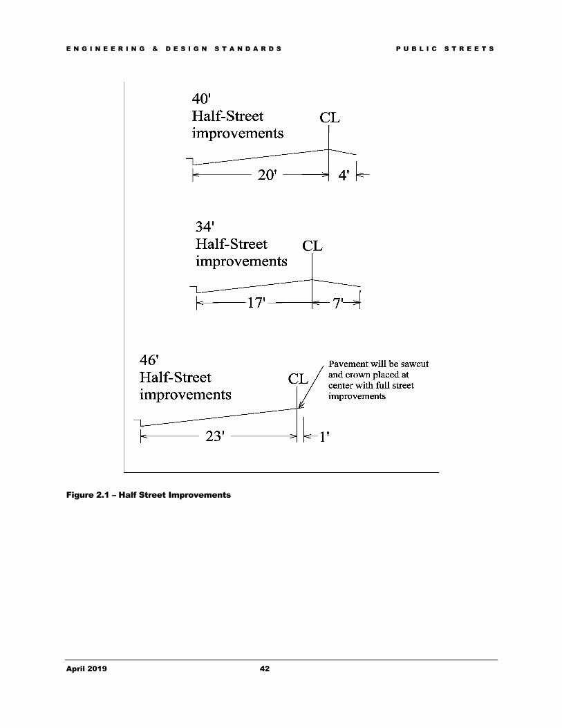
E N G I N E E R I N G & D E S I G N S T A N D A R D S P U B L I C S T R E E T S
April 2019 42
Figure 2.1 – Half Street Improvements

E N G I N E E R I N G & D E S I G N S T A N D A R D S P U B L I C S T R E E T S
April 2019 43
Figure 2.2 – Deceleration Lane Treatments

E N G I N E E R I N G & D E S I G N S T A N D A R D S P U B L I C S T R E E T S
April 2019 44
Figure 2.3 – Design Guidelines for Sight Triangles per AASHTO Green Book

E N G I N E E R I N G & D E S I G N S T A N D A R D S P U B L I C S T R E E T S
April 2019 45
Sight Visibility Triangle Approaching STOP Signs
*LU = lanes undivided **LD = lanes divided
STOP Sign Locations for Attached and Detached (or Absent) Sidewalks
Figure 2.4 – Sight Distance Requirements for Stop Signs
Cross-section of "a" STOP controlled road (feet) 2LU* (34') 12 2LU* (40') 11.5 2LU* (48') 18 3 LU* (46') 11.5 3 LU* (48') 11.5 4LD** (68') 11 4LD** (72') 11.5 5LU* (68') 12 6LD** (88') 10 6LD** (94') 11.5 7LU* (88') 11 2LU* with curb extensions narrowing travel way to single lane in each direction
5
Speed Limit Minimum of street
approaching Stopping
Sight Distance STOP sign (mph) (feet)
25 200 30 250 35 305 40 360 45 425 50 495
Minimum Stopping Sight Distances in this table are for 5 mph over the posted speed limit.

E N G I N E E R I N G & D E S I G N S T A N D A R D S P U B L I C S T R E E T S
April 2019 46
Figure 2.5 – Traffic Signal and Median Spacing
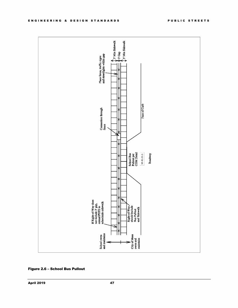
E N G I N E E R I N G & D E S I G N S T A N D A R D S P U B L I C S T R E E T S
April 2019 47
Figure 2.6 – School Bus Pullout

D E S I G N C U S T O M I Z A T I O N
48
Chapter 3 - Public Utilities - Water Provides minimum design criteria and guidance regarding the preparation of construction documents for public water system facilities as an extension to the City of Mesa public utility system.
he purpose of this chapter is to present to design professionals the standards to be used in preparing construction documents for private land development and city projects that involve the City’s public water utility system. The intent of this chapter is to provide general guidance to the design professional and City staff during the plan document preparation and plan review process.
Section 301 - General Information 301.1 The City of Mesa owns and operates a public water utility system, which provides potable water to the City of Mesa. The Arizona Water Company, a private utility company has been issued a certificate to serve a small area within the City of Mesa planning area (see Figure 3.1 – Water System Planning Area). In addition, the Town of Queen Creek has a small water service area within the City of Mesa Planning area.
301.2 Figure 3.1 shows the limit of the City of Mesa Water Planning Area. The majority of the City’s water system is within the corporate boundaries of Mesa but some components of the system are located within the jurisdictions of the Town of Gilbert and Maricopa County.
301.3 Mesa’s water system has been developed through a combination of Capital Improvement Projects (CIP) and private land developments, which include subdivision or lot development as well as public utility main extensions.
301.4 The City of Mesa Water Resources Department is responsible for the operations and maintenance of the public water utility system. Questions regarding the operations of the public water system should be directed to the Water Resources Department at (480) 644-4444.
Section 302 - Water Master Plan 302.1 The City of Mesa currently uses the 2018 Water Master Plan report prepared by the Water Resources Department.
302.2 The current Water System Master Plan and associated exhibits can be reviewed at the Water Resources Department offices at 640 N. Mesa Drive.
Chapter
3
T

E N G I N E E R I N G & D E S I G N S T A N D A R D S P U B L I C U T I L I T I E S - W A T E R
April 2019 49
Section 303 - Availability of City of Mesa Water 303.1 Questions pertaining to the availability of public water service from Mesa or system expansion or extension requirements to serve proposed new projects should be directed to Development Planning Section of the Development Services Department; PO Box 1466 Mesa AZ 85211-1466; (480) 644-3254.
Section 304 - City Code, Policies & Regulations 304.1 The design professional should be aware of and become familiar with the following aspects of the various regulations that pertain to land development within the City of Mesa and its utility service areas.
Section 305 - City Code 305.1 Title 9, Public Ways & Property contains information regarding the development of the public water system in association with private land development. Chapter 6 of Title 9 pertains to land division projects, while Chapter 8 deals with individual lot or parcel development (non-land division) projects.
305.2 An electronic version of the City Code can be referred to on the City of Mesa website at: http://www.mesaaz.gov/clerk/
Section 306 - City Ordinances 306.1 City ordinances stipulate the extension of public water mains across all public street frontages of the proposed project in order to facilitate the future extension of the public water system to serve other undeveloped frontages or other needs.
306.2 The Terms and Conditions for the Sale of Utilities Ordinance provides for and requires that in order to receive utility service from the City of Mesa, that all lands to receive utility service are developed in accordance with applicable regulations, standards and requirements.
306.3 An electronic version of the terms and conditions for the sale of utilities ordinance is located in the current Utility Rate Book available at:
https://www.mesaaz.gov/city-hall/office-of-management-budget/utility-rates
Section 307 - City Policy 307.1 City policy stipulates that the developer of a project is responsible for any main line extensions necessary for the proposed project in accordance with the adopted Water System Master Plan in order to receive water service.
307.2 Policy also requires public water mains be extended to serve adjacent parcels which may also require the dedication of public rights-of-way or easements to serve the adjacent parcels.
307.3 Open trenching (pavement cut) through public street pavement less than five (5) years old is subject to restrictions. Per City Code a pavement cut permit is required. See the Pavement Cut Application form for additional information. http://www.mesaaz.gov/home/showdocument?id=20815

E N G I N E E R I N G & D E S I G N S T A N D A R D S P U B L I C U T I L I T I E S - W A T E R
April 2019 50
Section 308 - Maricopa County Department of Environmental Services (MCESD) 308.1 The developer and associated design professionals are expected to be aware of and comply with the regulations of MCESD. See https://www.maricopa.gov/2618/Project-Approvals.
308.2 Maricopa County publishes the “Maricopa County Health Code”, portions of which regulate the construction of public water systems.
308.3 When stipulated by the Maricopa County Health Code for projects installing public water systems, provide a copy of the MCESD issued “Approval to Construct” Certificate.
308.4 Each approval to construct certificate shall then be followed up with an “Approval of Construction” Certificate that closes out the project after the system is completed. The developer is responsible to receive both approvals from the MCESD prior to the City’s acceptance of the water system.
308.5 The City of Mesa’s Public Water Supply number is 04-07-095.
Section 309 - Arizona Department of Environmental Quality (ADEQ) 309.1 In 1978, ADEQ published Engineering Bulletin No. 10; Guidelines for The Construction of Water Systems when it was part of the Arizona Department of Health Services. This edition of Bulletin No. 10 is still in effect and the City of Mesa requirements meet or exceed the standards established by Bulletin No. 10, Chapter VII, Distribution Systems.
Section 310 - Arizona Department of Water Resources (ADWR) 310.1 The ADWR regulates all groundwater wells within the State of Arizona as required by the Arizona Groundwater Management Code. Prior to drilling and installing pumping equipment, a “Notice of Intent” and an “Application for a Drilling Permit” must be obtained from and filed with ADWR.
310.2 The City of Mesa will complete the ADWR process & procedures for the public water infrastructure. Please note that the City of Mesa requires notification of all land development projects that are proposing to install a private well for water supply. ADWR prohibits the drilling of an exempt well on land if any part of the land is within 100 feet of the City of Mesa’s water distribution system (see ARS §45-454).
Section 311 - Public Water Supply & Distribution System Design 311.1 The following is the criteria for designing public water supply and distribution systems in the City of Mesa and its utility service area.

E N G I N E E R I N G & D E S I G N S T A N D A R D S P U B L I C U T I L I T I E S - W A T E R
April 2019 51
311.2 Water Demand Design Flows: Projected water demands shall be based on the unit flows shown in Table 3.1. Additional water demands associated with manufacturing processes, food processing or food services, central plants, large water features or other specific uses not listed below must be accounted for and included with the design analysis. Water demand calculations shall include the number and type of residential and non-residential units and square footages for non-residential buildings. Fire flow demands shall be provided separately, in addition to the unit flows below. See Section 317.25 for additional requirements for sizing water meters.
Table 3.1 - Average Day Water Demands By Land Use*
Residential Value Units
Low Density Residential (RR)< 1 Dwelling Units (DU)/ac 490 gpd/unit
Low Density Residential (ER) 1 – 2 DU/ac 470 gpd/unit
Medium Density Residential (LDR) 2 – 4 DU/ac 420 gpd/unit
Medium Density Residential (LMDR) 4 – 6 DU/ac 400 gpd/unit
Medium Density Residential (MDR) 6 – 10 DU/ac 254 gpd/unit
High Density Residential (MHDR) 10 – 15 DU/ac 194 gpd/unit
High Density Residential (HDR) 15+ DU/ac 154 gpd/unit
High Density Condominium 185 gpd/unit
Non-Residential Value Units
Hotel/Motel 150 gpd/room
Resort Hotel 350 gpd/room
Restaurant 1.5 gpd/sq.ft.
Commercial/Retail 0.2 gpd/sq.ft.
Commercial High Rise 0.4 gpd/sq.ft.
Office 0.4 gpd/sq.ft.
Institutional 3000 gpd/acre
Industrial1 1500 gpd/acre
Research and Development 1500 gpd/acre
Turf Irrigation 4400 gpd/acre
School 60 gpd/person
University – Boarded Student 100 gpd/person
University – Commuter Student & Staff 60 gpd/person *Values shown include inside and outside water use. 1) For additional water requirements associated with industrial processing for semi-conductor, aerospace, commercial laundry, metal products mfg., food/dairy/bottling, etc… the designer shall consult the Water Resources Department
311.3 Peaking Factors: Hydraulic calculations shall demonstrate that the planned water system provides sufficient capacity for both Peak Hour flows and Max Day demands plus fire flows. Peaking factors are as follows*:
Max Day = 2.0 x Ave. Day Demand

E N G I N E E R I N G & D E S I G N S T A N D A R D S P U B L I C U T I L I T I E S - W A T E R
April 2019 52
Peak Hour = 3.0 x Ave. Day Demand
*Peaking factors shall be increased as required for restaurants or other high-demand water uses.
Section 312 - Design Analysis 312.1 Projects within the City that impact the City’s existing water system will require a basis of design report to establish the projected water demands, available system capacity and proposed hydraulics of the planned water system. Basis of Design Reports (BDR) may also be required to demonstrate conformance of individual phases of development with the accepted master plan for that development. At a minimum, BDR’s shall include the following:
• Summary of the planned development, including land use information • Design parameters • Existing conditions • Projected Water Demands • Required fire hydrant flows in accordance with COM Fire Department and Fire Code
requirements • Proposed conditions, including planned waterline extensions and/or looping • Supporting exhibits, maps and modeling output as applicable
312.2 A hydraulic analysis is required for developments with multiple services, multiple fire lines, or as requested by the Water Resources Department. Requirements for hydraulic analyses shall satisfy the following requirements:
312.2.1 Projected water demands shall be based upon the unit demands listed in Table 3.1.
312.2.2 Use INFOWATER, WATERCAD, or EPANET or similar software for any computer modeling of water flows and pressures. 312.2.3 Analyze the water system for average day, maximum day, peak hour and maximum day with fire demand. 312.2.4 Minimum acceptable design pressures are 40 psi under Peak Hour demands and 20 psi during Max Day + Fire Flow demands. 312.2.5 Include input and output reports showing pipes and nodes with IDs, demand, pressure, elevation, hydraulic grades, length, pipe status (open/closed), diameter, velocity, and pipe head loss/1000 feet. Fire flow reports shall include critical junction nodes.

E N G I N E E R I N G & D E S I G N S T A N D A R D S P U B L I C U T I L I T I E S - W A T E R
April 2019 53
312.2.6 Include diagrams clearly showing all water pipe and node references. 312.2.7 In general, a Hazen-Williams C-coefficient of 130 shall be used for analyzing pressure head losses in water distribution mains. 312.2.8 The hydraulic model shall be calibrated using fire hydrant flow test results per the section below titled “Fire Hydrant Flow Tests”. Certified hydrant flow test results shall be included with the design report.
312.3 Project Specific Master Plan: A project-specific Water Master Plan will be required for phased developments, projects involving significant extensions of the public water system, or as directed by the Water Resources Department. Water master plans shall include system hydraulic models calibrated using a hydrant flow test per the section below or as directed by the City. The hydraulic model shall establish a skeletal water system and demonstrate adequate water design pressures (40 psi minimum under Peak Hour demands) and mainline hydrant flows (20 psi minimum during Max Day demand plus fire flows) for all phases of development.
312.4 The registrant is required to calculate the water demand of the proposed project. The resulting Basis of Design or Master Plan report shall be sealed and signed by the registrant and submitted to Development Services Department Planning along with a copy of the appropriate civil engineering design plans for the proposed public water distribution system.
312.5 Fire Hydrant Flow Tests: When required, fire hydrant flow tests shall be performed near the planned point of water system connection at the project site. The test shall be performed by a private, certified testing company. Tests shall be performed on weekdays between 6:00 a.m. and 8:00 a.m. and shall obtain a minimum residual pressure drop of 5 psi for accuracy purposes. A permit must be obtained from the City of Mesa Development Services Department prior to the test and a City Construction Inspector must witness and sign off on the hydrant test. The Development Services Department shall be notified a minimum of 48 hours before performing the flow test. Test results shall be submitted for review and acceptance along with the final plan submittal.
Section 313 - Water Service Agreement 313.1 Developments are required to file a “Water Service Agreement” document with the Maricopa County Environmental Services Department. This document is initiated by the developer's engineer, submitted to the Civil Plan Reviewer and executed by the Water Resources Department. This agreement will not be executed until the appropriate design analysis and water improvement Basis of Design report has been received and approved by the Water Resources Department. Questions regarding the water service agreement form should be directed to the MCESD.
Section 314 - Other Water Service Providers 314.1 Arizona Water Company: The Arizona Water Company, a private utility provider, has been issued a certificate by the State of Arizona to serve a small area of the City of Mesa. Projects within this area are required to coordinate with the Arizona Water Company regarding the design of public water systems. The general limits for the Arizona Water Company are shown on Figure 3.1

E N G I N E E R I N G & D E S I G N S T A N D A R D S P U B L I C U T I L I T I E S - W A T E R
April 2019 54
314.2 Town of Queen Creek: The Town of Queen Creek provides water service to a small area within the City of Mesa limits. The general limits for this area are shown on Figure 3.1. Projects within this area are required to coordinate with the Town of Queen Creek regarding the design of public water systems.
314.3 Private Water Company Identification: Land development projects involving certificated private water providers shall clearly indicate on the construction documents (i.e., civil engineering improvement plans) the ownership of the proposed private water system.
314.4 Billing Arrangements for Other City Services: Land development projects in which the water service will be provided by a certificated private utility shall establish a special billing arrangement with the City of Mesa Customer Service Division in order to receive public sewer service from the City of Mesa.
314.5 City of Mesa - Fire Plan Review: Projects with water service provided by a certificated private utility are subject to plan review for compliance with the City of Mesa’s requirements for fire protection systems.
Section 315 - Design Standards, Specifications & Guidelines 315.1 The City of Mesa public water system is a looped system that is grid-based and has been divided into multiple service zones and reduced-pressure areas. Locations where adjacent existing water mains provide water to different service zones are generally shown and identified in the City of Mesa Water Utility Quarter Section maps.
The City of Mesa currently utilizes the 2018 Water Master Plan Update prepared by City of Mesa Water Resources Department.
315.2 The City’s supply and distribution mains currently include the following components:
• Transmission Mains, which are larger than sixteen inches (16") in diameter;
• Distribution Mains, which are four inches (4") to sixteen inches (16") in diameter, and
• Services, which are lines connecting the distribution main to the regulating meter.
315.3 See the Public Water Main Design Section 316 that follows for current sizing requirements for the public water system.
Section 316 - Public Water Main Design 316.1 Design Considerations: During design the Engineer shall take into consideration means to flush and test the new main. A minimum flushing velocity of three (3) feet per second (fps) is required for mains up to and including sixteen inches (16") in diameter per AWWA C651. For mains larger than sixteen inches (16") in diameter where the required flushing velocity of three (3) feet per second (fps) may not be feasible, alternative cleaning methods may be used as described in AWWA C651. Air relief sizing and location shall be considered for flushing operations; for smaller mains, fire hydrants may be adequate.
316.2 The Engineer shall plan for future extensions to the water main(s) appropriate placement of valves, stub-outs, etc. to prevent future loss of service.

E N G I N E E R I N G & D E S I G N S T A N D A R D S P U B L I C U T I L I T I E S - W A T E R
April 2019 55
316.3 The Engineer shall make every effort to loop water mains throughout the development to limit dead ends. Long, dead-end water mains may have water-quality issues, including reduced chlorine levels and hot water complaints. New, permanent dead-end water mains shall be limited to a maximum length of 600 feet. For temporary/phased designs, dead-end water mains up to 1,200 feet may be allowed with approval of the Water Resources Department.
The engineer shall consider water-quality impacts such as water turnover and temperature when designing systems with temporary or permanent dead-end water mains. Whenever possible, temporary dead-end waterlines must be extended beyond paved surfaces to avoid pavement cutting at time of future connection and shall be equipped with a flushing pipe assembly installed out of traffic per MAG Standard Detail 390, Type A. An additional line valve shall be installed on dead-end lines, exclusive of mains that dead-end in a cul-de-sac, within 20 feet of the end of pipe to remove the necessity of shutting down water service to residences and businesses should the main be extended in the future.
Dead-end water mains are to supply no more than 25 water services. Developments containing 26 or more services require at least two different water supply sources. The Water Resources Department may require multiple water supply sources for non-residential developments with high domestic or fire flow demands or critical facilities that need redundant connections.
316.4 For water easements not located within a paved roadway or other paved access way, an all-weather access road is required if pipelines, valves, fire hydrants, or other appurtenance requiring City access are located within the easement. The access road shall have a minimum width of 10 feet and shall be paved or constructed of minimum 6- inch thick stabilized decomposed granite. Each end of the access road shall connect to a public street or private access way or a turn-around easement conforming to City of Mesa requirements.
316.5 Waterline plan sheets shall be provided for all water mains and shall include the following minimum information:
• All streets, alleys and easements. Streets shall be identified by name and show monument lines.
• Location of all above and underground utilities, structures, paving and other topographic features such as trees shall be shown. Utilities shall be identified by name, size and type. Pipe materials for existing water and sewer lines shall be indicated.
• Location of proposed waterlines, fittings and appurtenances such as fire hydrants, valves, meters, etc., shall be shown and identified by name, size and type.
• Location of all existing and proposed easements, utilities, fire hydrants and valves shall be referenced from the monument line.
• Location of all existing benchmarks shall be shown and identified by type.
• Location of all connections to existing waterlines with fittings clearly labeled and method of connection specified.

E N G I N E E R I N G & D E S I G N S T A N D A R D S P U B L I C U T I L I T I E S - W A T E R
April 2019 56
• Show bearings, curve information and stationing along the monument line.
• Meter service connection shall be either stationed along monument line or dimensioned
from property line. Also, provide offset dimension from monument line.
• Waterlines to be abandoned shall be clearly identified using a different line type or other method to distinguish them from existing waterlines that will remain in service.
316.6 Waterline profiles shall be provided for all water mains with diameters equal to or greater than 12-inches. All waterline profiles shall include the following minimum information:
• Existing and proposed utilities in and adjacent to the construction area;
• Existing utilities that cross the proposed waterline. Utilities shall be identified by type, size, pipe material, location (station) and elevation;
• Existing and finished grades along the monument line or water main centerline;
• Show all appurtenances, including valves, vaults and fittings, identified by name, size, type, station and elevation;
• Show invert elevations and stationing at all grade breaks, and the grade (%) and length
between grade breaks;
• Show joint restraint lengths with stationing;
• Show minimum design cover and vertical separation between water mains and other utilities.
316.7 Vertical Pipeline Alignment Considerations: Vertical alignments must be carefully considered in the design of transmission mains. Pipeline segments shall be set at a constant slope. A roller coaster type of vertical alignment shall be avoided to minimize air pocket formation at the high points of the profile. Design of the main shall provide for a minimum number of high and low points consistent with economic feasibility.
316.8 Wash Crossings: All wash crossings will be constructed using restrained joint ductile iron pipe. Bury requirements to place water lines under washes or channels shall be based upon the 100-year peak design discharge (Q100) in the channel or wash. The additional depth of bury shown below is in addition to the normal cover requirements. 100 year flow rate Additional depth of cover 1 to 49 cfs 1 foot 50 to 99 cfs 2 feet 100 to 499 cfs 3 feet More than 499 cfs Scour depth based on scour analysis required

E N G I N E E R I N G & D E S I G N S T A N D A R D S P U B L I C U T I L I T I E S - W A T E R
April 2019 57
316.8.1 Scour depth shall be estimated using Arizona State Standard Attachment (SSA) 5-96, Guideline 2, Level I, as published by the Arizona Department of Water Resources. The engineer will estimate the depth of scour and design the top of pipe to conform to Section 6-1.413. The engineer shall submit the scour analysis with the final plans.
316.8.2 All pipelines that must be located within the scour zone, or with less than the minimum required depth of bury as indicated above, may require additional protection against scouring at the discretion of the City. Water mains in easements at wash crossings shall not locate appurtenances such as manholes, fire hydrants, or valves within the 100-year flood elevation of the wash.
316.9 Sizing: The City of Mesa has standardized the supply and distribution aspects of the public water system. Water mains shall be sized to limit flow velocities to approximately 5 ft/s during Peak Hour demands and 10 ft/s during Maximum Day demand plus fire flow.
316.9.1 The minimum allowable diameter of a public water supply or distribution main is eight inches.
316.9.2 Six-inch diameter dead end lines are only permitted to fire hydrants and the six inch (6”) lines cannot be tapped and cannot be over 100’ long without fire flow calculations.
316.9.3 Eight-inch (8") water mains (minimum diameter) shall be installed on all public local streets.
316.9.4 Twelve-inch (12") water mains (minimum diameter) shall be installed on all mid-section street alignments unless otherwise directed.
316.9.5 Sixteen-inch (16") water mains (minimum diameter) shall be installed on all public arterial streets or section street alignments unless otherwise directed.
316.9.6 The preceding line size requirements shall apply unless the most current Water Master Plan requires a larger size.
316.10 Location: Public water mains are required to be located within dedicated public rights-of-way (ROW) or easements (PUFE, PUE). See Chapter 1, General Requirements concerning the dedication of ROW or easements. Public waterlines must be placed in locations/alignments that can be sufficiently accessed and maintained by City staff.
316.10.1 Water mains may be required on both sides of the street along water zone boundaries and along some major arterial streets with heavy demands. If so required, this is the responsibility of the proposed development.
316.10.2 Water mains located within a pressure zone that is not the intended service zone shall be located beneath the street paving or the future street paving. Location or alignment shall be as designated by the City. Public water mains located outside of their intended pressure service zone shall clearly identify on the plan view of the construction plans the pressure zone the main has been designated to serve.

E N G I N E E R I N G & D E S I G N S T A N D A R D S P U B L I C U T I L I T I E S - W A T E R
April 2019 58
316.10.3 When water mains for different service zones are located in a parallel configuration, they shall be placed on opposite sides of the street and on the side of the street or right-of-way serving their respective zones where possible. Brass markers indicating valve numbers and pressure zones in accordance with City of Mesa requirements shall be installed at each valve.
316.11 Horizontal Location: Public water distribution mains shall generally be located on the north or east side of local, collector, and arterial streets, and shall be placed under street pavement a minimum of three feet from the edge of the pipe to the lip of gutter.
316.11.1 Public water lines that are to be installed in public easements on private property are to be located under pavement. Generally, the water line shall be in the center of the public easement and the easement centered in the private drive aisle(s). Installations under parking stalls, landscape areas, fences/walls, retention basins and overhangs shall be avoided unless an engineering evaluation of the necessity and feasibility is approved in writing by the Water Resources Department.
316.11.2 No buildings or structures will be allowed to encroach on a public utility easement. Regardless of the easement width, buildings shall have a sufficient setback from the water or sewer pipe such that buildings, building foundations, building slabs, or structures will not be undermined or damaged by a water or sewer main break or subsequent repair. Buildings, building slabs or structures proposed outside of the easement but parallel to a water main within 12 feet, shall be required to submit structural and soil calculations signed and sealed by an Arizona Registered Professional Engineer. This report shall verify integrity of the proposed structure under the condition of a water main failure as well as verifying that the proposed structure and its foundations will not compromise the structural integrity of the water main. Similarly, the proximity of existing buildings and structures shall be considered in the placement of new water lines.
NOTE: The horizontal distance shall be measured from the edge of the building foundation to the OD of the water or sewer pipe.
Exceptions: Pre-Built/Fabricated Wood Shed-type Structures
Pre-Built/Fabricated Aluminum Shed-type Structures
Pre-Built/Fabricated Shade Structures
Free Standing Barbecue Islands Enclosures to Existing Garage/Carport/Patio where the existing concrete slab and roof will not be altered
316.11.3 Water mains larger than 16” diameter, such as for transmission purposes shall be located under public street pavement.
316.12 Vertical Location: All public water mains in arterial or collector streets shall have a minimum cover of forty-eight inches (48") over the top of the pipe.
316.12.1 Public water mains in other locations that are twelve inches (12") in diameter or larger shall have a minimum cover of forty-eight inches (48") over the top of the pipe.

E N G I N E E R I N G & D E S I G N S T A N D A R D S P U B L I C U T I L I T I E S - W A T E R
April 2019 59
316.12.2 Public water mains in other locations that are less than twelve-inches (12") in diameter shall have a minimum cover of thirty-six inches (36") over the top of the pipe.
316.12.3 Public water mains that are installed through undeveloped property (i.e., locations where the final finished grade elevation is not known, particularly along future street alignments), shall have a minimum cover of sixty-inches (60") over the top of the water lines.
316.12.4 Joint-trench installations containing City of Mesa water mains and gas mains shall be in accordance with Mesa Standard Details. Joint trench installations for water mains larger than 12-inches in diameter will be considered on an individual basis and require written authorization from the Water Resources Department and Energy Resources Department.
316.12.5 The City of Mesa strongly encourages the engineer to establish their alignments based on all available information regarding the existing conditions, existing and/or planned utilities and verify the location of the existing utilities by potholing. This is especially critical for the larger diameter water mains in order to avoid re-alignment of either the existing or proposed utility in the field.
316.13 Materials: All pipe for public water lines shall be in accordance with Section 610.3 of the M.A.G. Uniform Standard Specifications, except as modified below.
316.14 Waterlines; Six-inches (6") to Sixteen-inches (16"):
316.14.1 Ductile Iron Pipe (DIP) cement mortar lined, per M.A.G. Standard Specification 750 with polyethylene corrosion protection per M.A.G. Standard Specification 610.6. Pipe shall be Class 350 for diameters under 16" and Class 250 minimum for 16" pipe.
316.14.2 Materials for public water lines, up to and including 16", shall be per City of Mesa Approved Products List - Water. Polyvinyl Chloride (PVC) pipe is not an acceptable pipe material for public water main installations.
316.15 Waterlines Larger than Sixteen Inches (16"):
316.15.1 Ductile Iron Pipe (DIP) that is cement mortar lined and seal coated. Pipe is per M.A.G. Standard Specification 750 with polyethylene corrosion protection per M.A.G. Standard Specification 610.6. Pipe shall be Class 250 minimum.
316.15.2 Concrete Cylinder Pipe (CCP) shall be designed, manufactured and tested in accordance with AWWA C-303. Pipe must also comply with M.A.G. Standard Specification 758.
316.15.3 Polyvinyl Chloride (PVC) pipe is not an acceptable pipe material for public water main installations or extensions to the City of Mesa public water system.
316.15.4 Steel Pipe (AWWA C200) shall be designed, manufactured and tested in accordance with AWWA C-200. Pipe must also comply with M.A.G. Standard Specification 759.
316.15.5 All other pipe materials will be considered on a case-by-case basis. Projects desiring to utilize a different pipe material shall provide an analysis report providing the justification for the desired material during the plan review process.

E N G I N E E R I N G & D E S I G N S T A N D A R D S P U B L I C U T I L I T I E S - W A T E R
April 2019 60
316.16 Minimum Separation: In order to protect the public water supply from contamination the engineer shall maintain separation distances in accordance with the following:
316.16.1 The Maricopa County Health Code, Arizona Department of Environmental Quality Engineering Bulletin 10 and M.A.G. Standard Details 404 – 1, 404 – 2 and 404-3; Water and Sanitary Sewer Separation/Protection.
316.16.2 Mains conveying a higher quality of water shall be located above mains conveying a lower quality of water.
316.16.3 Minimum separations between water mains and sanitary sewer mains shall be:
• Six foot (6') horizontal as measured from the outside of pipes
• Two feet (2') Vertical as measured from the outside of pipes
316.16.4 Minimum Separation between potable water mains and a sanitary sewer manhole shall be:
• Six foot (6') horizontal as measured from the center of the manhole and the outside of the water main.
316.16.5 Minimum Separation between potable water mains and storm drain pipe and structures shall be:
• Two feet (2’) Vertical as measured from the outside of pipes. Water mains crossing less than the minimum but no closer than 12 inches shall have additional protection. Examples of additional protection are restrained joints, pipe casing, concrete encasement or as approved by Water Resources Department.
• Three feet (3’) horizontal, as measured from the outside of the pipe, manhole, catch basin, or other storm drain structure.
316.16.6 Water mains crossing less than two feet (2’) below a storm drain or culvert shall require additional protection such as the use of concrete encasement or a pipe casing.
316.16.7 There shall be a minimum of three feet (3') of horizontal separation and one foot (1') vertical separation between public water mains and non-City utilities (electric, telephone, CATV, etc.).
316.16.8 Sensitive or high-capacity utility lines, such as primary electric lines, high pressure gas lines, and fiber optic, CATV, or telephone trunk lines, shall not cross above a water main without written approval from the Water Resources Department.
316.16.9 There shall be a minimum of 5’ of horizontal separation from base of tree trunk to outside of water main.
316.16.10 There shall be a minimum of three feet (3’) of horizontal separation between the outside of streetlight or traffic signal pole foundations and the outside of water mains.
E N G I N E E R I N G & D E S I G N S T A N D A R D S P U B L I C U T I L I T I E S - W A T E R
April 2019 61
316.17 Individual house services or building plumbing beyond dedicated public right-of-way or public easements shall conform to the latest Plumbing Code adopted by the City of Mesa.
316.18 Water Line Protection: Where conditions prevent the proper separation of water and sewer mains, extra protection of the water main is required. The type of extra protection required or allowed shall be per the current Maricopa County Health Code, Arizona Department of Environmental Quality Engineering Bulletin 10 and/or M.A.G. Standard Details 404 – 1 & 404 – 2; Water and Sanitary Sewer Separation/Protection.
316.19 Vertical Realignment: Vertical realignment by means of pipe deflection shall not exceed 2/3 of the manufacturer’s recommendation. Deflection angle information shall be given on the plans. Vertical realignment by means of bends and offsets shall be per M.A.G. Standard Detail 370. The City of Mesa allows for water mains six inches (6") to sixteen inches (16") in diameter to be realigned per Detail 370. Water lines larger than sixteen inches (16") shall have all vertical realignments detailed by the Engineer on the construction plans and shall be subject to Water Resources Department approval.
316.20 Corrosion Protection: Installation of Ductile Iron Pipe requires Polyethylene Corrosion Protection per Section 610.6 of the M.A.G. Uniform Standard Specifications, AWWA C-105 10-point soil evaluation and/or as specified by the City.
316.20.1 A corrosion monitoring system shall be installed on concrete cylinder and steel water mains. Ductile Iron Pipe and Fire Hydrants shall also be isolated from concrete cylinder and steel water mains by the use of flange isolation kits equipped with test leads for monitoring purposes.
316.20.2 Tapping sleeves shall incorporate a flange isolation kit between the tapping sleeve and the ductile or cast iron valve.
316.20.2 Concrete cylinder water transmission lines shall be designed and installed to provide for future cathodic protection. Continuity tests shall be conducted and certified by a qualified corrosion-engineering firm employed by the developer or their representatives.
316.20.4 Ductile iron, steel, or concrete cylinder pipe installed parallel to, or crossing, high voltage buried or overhead electric lines may require additional passive or active corrosion protection systems, and shall be evaluated by a National Association of Corrosion Engineers (NACE) Certified Cathodic Protection Specialist.
316.20.5 Designs for water transmission mains with diameters of 20” and larger require a corrosion study. The study shall be completed by a Cathodic Protection Specialist. The study shall include the following as a minimum:
• Soil borings taken every 500 feet (maximum spacing) along the proposed water main alignment. More frequent soil borings may be required as determined by the Cathodic Protection Specialist. Borings shall be taken at the proposed water main elevation below finished grade.
• Soil borings shall be evaluated in accordance with AWWA C105 Table A.1 (Soil-Test Evaluation) and shall include the parameters listed below as a minimum regardless of pipe

E N G I N E E R I N G & D E S I G N S T A N D A R D S P U B L I C U T I L I T I E S - W A T E R
April 2019 62
material. For concrete cylinder pipe, additional parameters may be required as determined by the Cathodic Protection Specialist.
o Resistivity (water-saturated soil box)
o Resistivity (minimum)
o pH
o Redox Potential
o Sulfides (positive, trace, or negative)
o Moisture (poor, fair, or good drainage).
• Each soil boring shall be graded per AWWA C105 Table A.1 using the 10-point system. Averaging across multiple soil borings is not allowed. If any soil boring location has a score of 10 points or more, additional corrosion monitoring and protection measures (in addition to polywrap) may be required as determined by the Cathodic Protection Specialist..
• A stray current evaluation shall be completed to determine the impact of existing or proposed steel gas lines, high-voltage electric lines, railroad crossings or other systems generating stray currents.
• Provide construction details for corrosion test stations, bonded joints, flange isolation kits, exothermic welds, anodes and other corrosion monitoring and protection provisions as required.
• Corrosion monitoring and protection systems, when required, shall conform to the following:
o Test station maximum spacing is 1,000 feet.
o Test stations shall be placed in Christy G5C locking traffic boxes (or approved equal) with 6” thick 24-inch diameter Class B concrete ring.
o Test station lids shall read “CP Test Water”.
o All test wires shall be identified on the plans and labeled at the time of installation.
• Provide a narrative summarizing soil corrosivity, stray current potential and recommended corrosion monitoring and protection provisions as applicable. When corrosion monitoring is required, the report shall include recommended testing intervals (annual, semi-annual, etc.).
• Prior to acceptance of the water main by the City, a commissioning report shall be prepared by a NACE-certified Cathodic Protection Specialist and provided to the City

E N G I N E E R I N G & D E S I G N S T A N D A R D S P U B L I C U T I L I T I E S - W A T E R
April 2019 63
demonstrating satisfactory installation and test results of corrosion monitoring and protection systems as applicable.
316.21 Couplings, Joints, Gaskets and Flanges: Couplings, Joints, Gaskets and Flanges shall conform to Section 610 of the M.A.G. Uniform Standard Specifications, unless otherwise approved.
316.22 Restrained Joints: Restrained joints are required at all bends, elbows, tees, crosses, dead ends, stubs, curb stops, fire hydrants, taps, valve locations on large diameter water mains, etc where water flow changes direction or is stopped.
316.22.1 Acceptable restrained joint systems include the following:
• Thrust blocking per M.A.G. Standard Detail 380 for water mains that are six inches (6") through sixteen inches (16") in diameter.
• Ductile Iron Pipe (DIP) joint restraint shall comply with M.A.G. Standard Detail 303. Deviations from restrained lengths presented in Detail 303 must be supported by engineering calculations and accepted by the Water Resources Department prior to construction.
• Refer to the City of Mesa Approved Products List for acceptable mechanical joint and push-on joint restraint systems and products.
• Flanged joints for above ground piping or piping within a vault, which may require restrained flexible couplings for dismantling and reassembly (flanged coupling adapters are not allowed).
• Continuously welded joints with variable pipe cylinder thickness for Concrete Cylinder Pipe water mains.
• Thrust restraint requirements for closed in line valves shall be considered, noting that when a valve is closed the differential pressure may be reversed.
316.22.2 Joint restraints shall be clearly shown in profile sheets for water mains with diameters 12-inches and above. Restraint lengths shall include stationing callouts at the beginning and end of each segment of pipe to be restrained.
316.22.3 When the water main is 20 inches (20") or larger, the engineer shall submit joint restraint calculations and details to the Water Resources Department for review and approval.
316.23 Additional Requirements for Transmission Mains:
316.23.1 The Water Resources Department must approve the location of outlets or tie-ins to existing or proposed transmission mains.
316.23.2 In general, service connections to existing or planned transmission mains constructed of concrete-cylinder pipe (CCP) or pre-stressed concrete cylinder pipe (PCCP) are prohibited.

E N G I N E E R I N G & D E S I G N S T A N D A R D S P U B L I C U T I L I T I E S - W A T E R
April 2019 64
316.23.3 Planned connections to existing CCP or PCCP mains will be evaluated by the Water Resources Department on an individual basis.
316.23.4 Access manholes shall be installed on 36-inch diameter and larger transmission mains on each side of line valves and spacing shall not exceed 2600 feet unless otherwise approved in writing by the Water Resources Department.
316.23.5 Connections to Water Transmission Mains:
• Water transmission mains are subject to extended outages for maintenance or repair work. Therefore, water system extensions to serve development shall connect in a manner that provides adequate redundancy and shall conform to the guidelines below unless otherwise approved in writing by the Water Resources department.
• Designs shall be configured to maintain water service to the site in the event the adjacent transmission main segment is taken out of service (valve-to-valve). Dual feeds to the same transmission main must be separated by an isolation valve on the transmission main, unless otherwise approved in writing by the Water Resources Department.
• Water distribution mains shall be installed parallel to transmission mains and must be extended across the frontage of developments unless an acceptable internal water main loop is provided. Internal loops must allow for future connections to adjacent development.
• Isolation valves shall be installed at all transmission main connections.
• When connecting ductile-iron pipe to an existing concrete cylinder pipe (CCP) or prestressed concrete cylinder pipe (PCCP) transmission main, flange-isolation kits shall be installed at all connection points, including tapping sleeves between the flange and the valve.
316.24 Trench Backfill & Pavement Replacement: The contractor is responsible for backfilling and replacing pavement in all public street excavations per the City of Mesa Standard Detail M-19.04.1 and the Policy Statement for Street Trench Backfilling and Pavement Replacement, revised September 29, 1999. Copies of the policy statement are available online from the Engineering Department web pages at: http://www.mesaaz.gov/home/showdocument?id=12294 Pipe bedding, haunching, and backfill material shall be ABC per M.A.G. Specification Section 702 or CLSM per M.A.G. Specification Section 604. Reclaimed concrete, pavement material, and lime-treated ABC are prohibited for use for pipe bedding, haunching, and initial backfill (i.e. material in the pipe zone).

E N G I N E E R I N G & D E S I G N S T A N D A R D S P U B L I C U T I L I T I E S - W A T E R
April 2019 65
Section 317 - Water Appurtenances 317.1 Valves: The City of Mesa requires the installation of isolation valves to facilitate the operation, maintenance and expansion of the water distribution system. The types of valves required are dependent on the water main size. The City has standardized the sizes, types and locations of the water valves, with the specifics discussed below.
317.2 Water line valves shall meet or exceed the pressure classification of the water line.
317.3 Valve Spacing: Valve spacing shall be in accordance with the Maricopa County Health Code, Arizona Department of Environmental Quality Engineering Bulletin 10 and City of Mesa requirements:
317.3.1 Maximum valve spacing on mains less than twenty inches (20") in diameter is eight hundred feet (800').
317.3.2 Maximum valve spacing on mains twenty inches (20") or larger in diameter is one-half (½) of a mile.
317.4 Actual valve spacing will be less due to several variable conditions such as the location of street intersections, tees or branches, crosses, zone splits, phasing boundaries, etc., the actual valve location shall be as determined by the City.
317.5 Valve Locations: The City of Mesa requires valves to be installed on all feeder branches so that the distribution system can be segmented and a limited number of customers would be affected during a shutdown for maintenance or extension.
317.5.1 Valves are required on each branch of a cross or tee and in other locations as designated by the City of Mesa Water Resources Department. In locations where adjacent tees or crosses are placed with no intermediate laterals or waterline connections, valves are not required at both locations.
317.5.2 A valve shall be located on each side of a canal, wash, railroad, or freeway crossing. Avoid valve locations in curbs, sidewalks and driveways and valley gutters.
317.5.3 Valves on lateral connections from tees or crosses in arterial or mid-section streets shall be located behind crosswalks.
317.6 Gate Valves:
317.6.1 Resilient seat gate valves mounted vertically are required on water mains thirty-six inches (36") in diameter or smaller. Horizontally mounted gate valves are generally not allowed and will be reviewed on a case by case basis.
317.6.2 In general, all gate valves shall be direct-buried and shall not be located in vaults.
317.6.3 All gate valves shall conform to Section 630.3 of the M.A.G. Uniform Standard Specifications, with the following exceptions:

E N G I N E E R I N G & D E S I G N S T A N D A R D S P U B L I C U T I L I T I E S - W A T E R
April 2019 66
• Bypass valves are not required on gate valve assemblies 24" and smaller, unless requested by Water Resources
• Due to the rigidity of the joint, valves shall not contain flanged ends except when placed in vaults. Exceptions include hydrant laterals installed per M.A.G. Detail 360, and may include valves installed on large diameter transmission mains, with prior written approved by the Water Resources Department.
317.6.4 All valves require a minimum clearance of 24” from top of valve nut to finish grade.
317.6.5 Valve blocking details or requirements shall be provided for all valves greater than 12” in diameter.
317.7 Butterfly Valves:
317.7.1 Butterfly valves are approved for installation on water mains, forty-two inches (42") and larger in diameter where a resilient gate valve cannot be installed.
317.7.2 At the discretion of the Water Resources Department, butterfly valves with actuators located in manholes may be required. Provide minimum 24” clearance to top of valve from finish grade.
317.7.3 The engineer is required to coordinate with the contractor the submittal of certified shop drawings to the City of Mesa Engineering Department Construction Services Division for review and approval prior to the shipment of the butterfly valves.
317.7.4 All butterfly valves shall conform to Section 630.5(A) of the M.A.G. Uniform Standard Specifications.
317.8 Tapping Sleeves and Valves: Tapping sleeves and valves (TS&V) are to be installed per M.A.G. Standard Detail 340, which covers the installation of taps on existing six inch (6") through sixteen inch (16") ACPor DIP water mains.
317.8.1 TS&Vs are not allowed on same size pipes. Instead, install “cut in” tee.
317.8.2 A tee is preferred over a TS&V if the tapped water main can be shut down with no service disruption.
317.8.3 Connections to aging asbestos-cement pipe (ACP) should be made by cutting in a new section of ductile iron pipe with a ductile iron tee and proper joint restraint in lieu of a tapping sleeve. See City of Mesa Standard Detail M-52.
317.8.4 Tapping sleeves on newer sections of ACP may be allowed at the discretion of the Water Resources Department.
317.8.5 Reverse taps for new mains and services (taps to side of main away from project receiving tapped pipe) are strongly discouraged and require written permission from the Water Resources Department.

E N G I N E E R I N G & D E S I G N S T A N D A R D S P U B L I C U T I L I T I E S - W A T E R
April 2019 67
317.8.6 The engineer shall detail on the improvement plans all wet taps not addressed by M.A.G. Detail 340.
317.8.7 Only City-approved contractors shall perform all wet taps on the City of Mesa public water system. A list of the currently approved contractors is accessible at the following address: http://mesaaz.gov/business/engineering/approve-products-equipment-natural-gas-line-contractors
317.8.8 Tapping sleeves shall conform to section 630.4 of the M.A.G. Uniform Standard Specifications. A list of the currently approved tapping sleeve and valve assemblies is accessible at: http://mesaaz.gov/business/engineering/approve-products-equipment-natural-gas-line-contractors
317.9 Zone Inter-tie Valves: Zone Inter-tie valves between adjacent water service zones are not allowed.
317.10 Pressure Reducing Valves on Public Mains: Pressure reducing valves on public mains are not allowed unless approved in writing by the Water Resources Department.
317.11 Pressure Reducing Valves – Private Systems: Pressure reducing or regulating valves are required to be installed on the customer side of the water meter, where the static pressure exceeds 80 P.S.I. or as required per the latest adopted Plumbing Code. Maintenance of the pressure-reducing valve shall be the customer’s responsibility.
317.12 Valve Box & Covers: All water valves on the City of Mesa public water system are required to have a valve box installed. All valve boxes and covers shall be installed per M.A.G. Standard Detail 391-1, Type “C”.
317.13 Air Release, Air/Vacuum, & Combination Air Valves:
317.13.1 Distribution Mains - 16" And Smaller:
Per AWWA Manual of Practice M-51, air valves may not be needed in distribution piping systems where fire hydrants and service connections provide means for venting trapped air. The vertical alignment of distribution mains shall be carefully considered to minimize the potential for trapped air within distribution pipelines.
Unless otherwise indicated by project specific conditions, which may include excessive slope, lack of service connections or fire hydrants, or low pressure operating conditions such as well collection lines, air valves shall not be installed on distribution mains.
During design the Engineer shall evaluate the pipeline design to determine whether air relief, air/vacuum, or combination air valves are warranted. To the extent practical, alternative pipeline alignments should be considered to avoid air valves. Approval of the use of air valves on distribution mains shall be on a case by case basis, in writing, by the Water Resources Department.
Air valves shall be installed per City of Mesa Standard Details.

E N G I N E E R I N G & D E S I G N S T A N D A R D S P U B L I C U T I L I T I E S - W A T E R
April 2019 68
A list of currently approved air valves is available at: http://mesaaz.gov/business/engineering/approve-products-equipment-natural-gas-line-contractors
317.13.2 Transmission Mains - Larger Than 16":
Air release, air/vacuum, and combination air valves utilized on transmission mains shall be designed and sized per AWWA Manual of Practice M-51. Air valves shall be compliant with AWWA C512 Air-Release, Air/Vacuum, and Combination Air Valves for Waterworks Service, latest edition.
The vertical alignment of transmission mains shall be carefully considered to minimize the number of air and vacuum valves necessary for safe and efficient operation. Large diameter vacuum, or combination air/vacuum valves shall be installed above ground in lockable cages with 3-foot minimum clearance on all sides and sufficient clearance for opening or removing cages for maintenance activities. Installation details shall be provided on the construction plans and shall be reviewed by the Water Resources Department.
Design Engineer shall submit calculations supporting the design location, selected valve type, and valve sizing to the Water Resources Department for approval for all transmission mains.
317.14 Vaults & Boxes: Meter boxes adjacent to or within a storm water retention basin shall be located so that the bottom of the box shall be above the high water elevation for the required retention volume.
317.14.1 Standard Water Meters (3/4"& 1" Meter Sizes): Water meters of these sizes require the installation of a water meter box & lid per Mesa Standard Detail M-49.01, M-49.02 and M-49.03.
317.14.2 Standard Water Meters (1 ½", 2" Meter Sizes): Water meters of these sizes require the installation of a water meter box & lid per Mesa Standard Detail M-29
317.14.3 Parallel 2-inch water meters for 3” service: Install per Mesa Standard Detail M-28.02.
317.14.4 Large Water Meters (4", 6", 8" & Two Manifolded 6” Meter Sizes): Meters of these sizes shall be installed in accordance with Mesa Standard Details M-27.01.1, M-27.02.1 or M-28.01.1 (or M-30.01 and M-30.02 with special permission).
317.15 Specialized Vaults (Pressure Relief/Sustaining): Where the installation of a valve or meter vault has been approved or required, the following guidelines shall apply:
317.15.1 Where possible, the vault should be located out of the pavement (i.e., behind the curb or sidewalk).
317.15.2 The engineer shall design & detail all necessary realignments of the waterline to accommodate the size of the vault including the adjusting rings, frame & cover on the access manhole.
E N G I N E E R I N G & D E S I G N S T A N D A R D S P U B L I C U T I L I T I E S - W A T E R
April 2019 69
317.15.3 When it is necessary for the vault to be installed within an existing or future paved public roadway, the top of the vault should be three feet (3') below the finished pavement grade.
317.15.4 The engineer shall detail the vault installation on the improvement plans.
317.16 Fire Hydrants: Fire hydrants in the public rights-of-way, public easement, or on public properties shall be installed per M.A.G. Standard Details 360 and 362.
317.16.1 Isolation valves for public fire hydrants shall be placed directly on the distribution or transmission main tee.
317.16.2 Maximum fire hydrant spacing is five hundred feet (500') as measured along the fire truck travel path. Fire hydrants separated from a subdivision, building or other development by a continuous fence, wall or other obstruction cannot be counted as providing protection to that subdivision or development. For example, where a residential subdivision is separated from its perimeter street by a continuous fence, fire hydrants shall be installed along the perimeter street and internally along the streets within the subdivision, with hydrant spacing measured along the route of travel of the fire engine, not over the fence. Actual spacing may be less due to several variables, such as intersections, etc.; spacing will be as determined by the City.
317.16.3 The normal location of fire hydrants is the northeast corner of public street intersections.
317.16.4 Mesa fire hydrants not in Mesa ROW shall be in a PUE or PUFE, with the easement extending at least 5 feet beyond the hydrant.
317.16.5 Fire hydrants shall have three foot (3’) flat clear zone and shall not be located in retention basins. All fire hydrants should maintain a 6-foot horizontal clearance from utility and above ground structures to provide adequate access for maintenance and replacement.
317.16.6 Fire hydrant installations on building fire lines are prohibited.
317.17 Fire Hydrant Acceptable Manufacturers and Models: The City has standardized the manufacturers and models that are allowed to be installed where the City of Mesa provides, or intends to provide fire protection services. The City of Mesa Water Resources Department reserves the right to change or amend the list of approved fire hydrants without advance notice or publication. The current list of acceptable fire hydrants can be found on the Approved Products List for Water:: http://www.mesaaz.gov/home/showdocument?id=3258
317.17.1 The City of Mesa is not responsible to maintain or for the removal & replacement of private fire hydrants.
317.17.2 The City of Mesa Fire Department shall be notified of properties that have private fire hydrants that are beyond the maintenance responsibilities of the City of Mesa.
317.17.3 Fire Hydrants shall be configured with bronze-on-bronze seating.
317.18 Fire Lines and Building Sprinkler Lines: Water lines that are designed to solely provide water supply to a fire sprinkler system, also known as fire lines, from the public water system shall be installed per Mesa Standard Detail M-31.07.

E N G I N E E R I N G & D E S I G N S T A N D A R D S P U B L I C U T I L I T I E S - W A T E R
April 2019 70
317.18.1 Fire line sizes shall be determined based on flow test data provided by the engineer for design of the project.
317.18.2 Show all fire lines on the civil site final plans.
317.18.3 Fire service lines shall be installed perpendicular or radial to the main line within the right-of-way or easement.
317.18.4 All on-site fire line construction shall comply with the M.A.G. Standard Specifications and Details and the City of Mesa Supplements.
317.18.5 Private fire lines with hydrants are private pipe systems connected directly to the City water system. Private fire lines, by the nature of their function and use, are susceptible to backflow. Consequently, they are subject to the requirements for backflow prevention within this manual. See Backflow Prevention section below for information regarding cross-connection devices that are required to be installed on fire lines.
317.18.6 A fire line shall be utilized for fire protection only and shall serve only a single property.
317.18.7 All maintenance of the private fire line is the responsibility of the property owner and begins at the public right-of-way or water easement line.
317.19 Water Services: Locate all water services either within dedicated right-of-way or public easements (PUE. or PUFE).
317.19.1 The water service line and meter shall be sized based upon the total daily demands for the development and the recommended maximum capacity of the meter.
317.19.2 That portion of the water service from the water main up to, and including the meter is public and will be maintained by the city. That portion of the water service from the meter into the site is private and will be maintained by the property owner. Design of the private on-site portion of the water service shall comply with the current Plumbing Code and may require a pressure regulating valve.
317.19.3 Service lines are necessary to meet domestic, fire, and irrigation demands. Residential fire sprinkler and irrigation demand is usually supplied through the domestic service line and meter. Commercial developments typically will use separate meters for building and landscape service and provide separate lines for fire protection.
317.19.4 Final plans shall show locations of service lines and meters to each unit referenced with stations and dimensions, or offsets, from the street centerline or monument line. Service lines and meter boxes will be located within a public right-of-way, easement within a private street tract, or a utility easement. Meters are to be accessible to city workers and be located as close as possible to the water main.
317.19.5 Do not place water service lines and meters in driveways, sidewalks, washes, or detention basins.
E N G I N E E R I N G & D E S I G N S T A N D A R D S P U B L I C U T I L I T I E S - W A T E R
April 2019 71
317.19.6 Existing water and fire lines not used by a development shall be noted on the plans to be abandoned at the main by the contractor.
317.19.7 Water service connections to transmission mains with diameters 20” and above are not allowed without written approval from the Water Resources Department.
317.19.8 Water services shall be perpendicular to the main and in a straight line between the meter and main, except if necessary at line end in a cul-de-sac.
317.19.9 Water services can be located in a “joint-trench” with natural gas services. Sanitary sewer services, as well as non-City utilities shall utilize separate trenches when located within dedicated right-of-way or public easements. See Mesa Standard Detail M-58. Current plumbing code requirements apply for all joint-trench installations on the private side of the meter.
317.19.10 The City of Mesa has standardized service sizes that are acceptable for connection to the public water system.
317.19.11 Service size shall be equal to, or one size larger than the proposed water meter size (i.e., a ¾" meter on a 1" service would be acceptable whereas a ¾" meter on a 2" service would not).
317.19.12 Where a service size must be adapted for a different size water meter, there shall be approximately forty-eight inches in service piping on either side of the water meter box before a transition to a different size or material occurs.
317.19.13 Three-quarter inch (3/4") through two-inch (2") water services shall be installed per Mesa Standard Detail M-49.01, M-49.02 and M-49.03.
317.19.14 Water services larger than two-inch (2") in diameter on an existing public water main shall be installed via a wet tap per the “Tapping Sleeves & Valves” section above.
317.19.15 Projects that require a three-inch (3") water service are required to install two two-inch (2") water services, which are manifolded per Mesa Standard Detail M-28.02.
317.19.16 The water service size shall be noted on the improvement plans at all water service locations.
317.19.17 Water Services to Multiple Dwellings/Buildings: For those projects that involve the subdivision of land that will result in individual ownership of land (i.e., condominiums, town homes, patio homes, etc.), the City of Mesa requires that individual services be provided to each unit; except that, a group of structures or parcels may be served by one (1) meter and service connection when the real property under ownership by multiple parties is governed by a homeowners’ association or a unit owners’ association.
317.19.18 For projects in which the property will remain under one ownership (i.e., apartments, residential duplex, etc.), the City allows the use of one of the following options:
317.19.18.1 Individual services to each unit.
317.19.18.2 One service to a single building.

E N G I N E E R I N G & D E S I G N S T A N D A R D S P U B L I C U T I L I T I E S - W A T E R
April 2019 72
317.19.18.3 One service to the entire project site.
317.19.19: Water service connections to fire hydrant lateral pipes are prohibited.
317.20 Manifolding Water Services: The City of Mesa does not allow water services & meters to be manifolded together except as follows:
317.20.1 Three-quarter inch (3/4") through two-inch (2") services, which will serve both domestic and landscaping demands, may manifold one service to serve two separate meters for each type of use in accordance with Mesa Standard Detail M-49.03.
317.20.2 Two-inch (2") services are allowed to be manifolded together after the water meters in lieu of a three-inch (3") service and meter in accordance with Mesa Standard Detail M-28.02.
317.21 Water Meters: The City of Mesa requires that all service connections to the public water system be metered.
317.22 All water meters to be installed on the public water system shall be purchased from the City.
317.23 Water meters are to be located within dedicated public right-of-way or easements and installed on or at the property or easement line in accordance with Mesa Standard Detail series M-49.
317.24 Meters shall be located to avoid crossing back through the right-of-way or easement with a service line.
317.25 Prior to installation of meters for non-residential service, calculations shall be provided to the Water Resources Department establishing proposed water service and meter sizes. These calculations are in addition to those specified in Section 311 and shall include minimum, average and peak flows for each meter, including domestic, landscape, subtractive meters, etc. Peak meter flows shall be calculated using the Plumbing Code currently adopted by the City, or other methods as approved by Water Resources.
317.26 The water meter size shall be noted on the improvement plans at all water meter locations.
317.27 The designer shall provide on the improvement plans the address of the water meter. Submit a plan that shows the meter location(s) to the permit services section for addressing.
317.27.1 Acceptable water meter flows by size are as follows:
3/4" = 0.25 to 30 gpm 1" = 0.50 to 50 gpm 1-1/2" = 1 to 100 gpm 2" = 1 to 160 gpm 2" x 2 (parallel) = 1 to 300 gpm 4" turbine = 15 to 800 gpm 4" single-jet or compound = 0.75 to 500 gpm 4" fire-rated = 2 to 1,250 gpm 6" turbine = 30 to 1,600 gpm
City of Mesa Water Meters Three-quarter Inch (3/4") Short One-inch (1") One and one half Inch (1 ½") Two Inch (2") Four Inch (4") Six Inch (6") Eight Inch (8")

E N G I N E E R I N G & D E S I G N S T A N D A R D S P U B L I C U T I L I T I E S - W A T E R
April 2019 73
6" compound = 1.5 to 1,000 gpm 6" fire-rated = 2 to 2,500 gpm 8" fire-rated = 2 to 4,500 gpm 10" fire-rated = 10 to 5,000 gpm
317.28 Water Meters for Multiple Units/Buildings: Projects that involve or will result in individual ownership of the land, unit or building are required to install a separate water meter for each building or unit thereof.
317.28.1 Projects that will remain under one ownership shall select one of the following options:
• Individual water meters to serve each unit;
• One meter to serve a single building and all units or suites contained within; or
• A “master meter” to serve the entire project site.
317.29 Backflow Protection: The City of Mesa is responsible for protecting the quality of the public water supply. To prevent contamination of the public water supply by backflow and cross connections, the City has identified types of developments requiring backflow prevention, and approved types of devices to prevent backflow.
317.29.1 The following types of backflow prevention devices are approved for use within the City of Mesa Water Utility Service Area:
• Reduced Pressure Principle (RP) Device
• Double Check Valve (DC) Assembly
• Air Gap Separation (AG)
• Pressure Vacuum Breaker (PVB)
• Spill Resistant Vacuum Breaker (SVB)
317.29.2 All backflow preventive devices shall be approved by the “Foundation for Cross Connection Control and Hydraulic Research of the University of Southern California and the City of Mesa Water Resources Department.
317.29.3 Per 8-1-6 of the Mesa City Code, the types of developments presented in Table 3.2 require an approved backflow preventive device. The City of Mesa has identified the backflow prevention device for standard installation at each service connection.
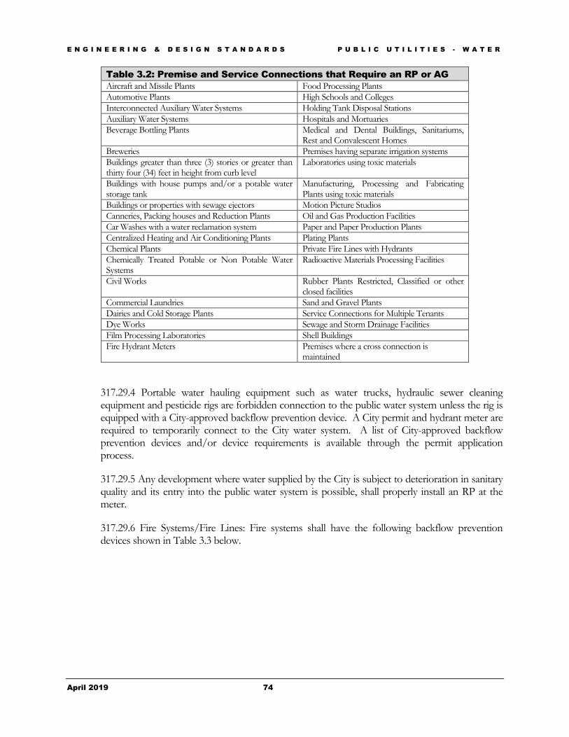
E N G I N E E R I N G & D E S I G N S T A N D A R D S P U B L I C U T I L I T I E S - W A T E R
April 2019 74
Table 3.2: Premise and Service Connections that Require an RP or AG Aircraft and Missile Plants Food Processing Plants Automotive Plants High Schools and Colleges Interconnected Auxiliary Water Systems Holding Tank Disposal Stations Auxiliary Water Systems Hospitals and Mortuaries Beverage Bottling Plants Medical and Dental Buildings, Sanitariums,
Rest and Convalescent Homes Breweries Premises having separate irrigation systems Buildings greater than three (3) stories or greater than thirty four (34) feet in height from curb level
Laboratories using toxic materials
Buildings with house pumps and/or a potable water storage tank
Manufacturing, Processing and Fabricating Plants using toxic materials
Buildings or properties with sewage ejectors Motion Picture Studios Canneries, Packing houses and Reduction Plants Oil and Gas Production Facilities Car Washes with a water reclamation system Paper and Paper Production Plants Centralized Heating and Air Conditioning Plants Plating Plants Chemical Plants Private Fire Lines with Hydrants Chemically Treated Potable or Non Potable Water Systems
Radioactive Materials Processing Facilities
Civil Works Rubber Plants Restricted, Classified or other closed facilities
Commercial Laundries Sand and Gravel Plants Dairies and Cold Storage Plants Service Connections for Multiple Tenants Dye Works Sewage and Storm Drainage Facilities Film Processing Laboratories Shell Buildings Fire Hydrant Meters Premises where a cross connection is
maintained
317.29.4 Portable water hauling equipment such as water trucks, hydraulic sewer cleaning equipment and pesticide rigs are forbidden connection to the public water system unless the rig is equipped with a City-approved backflow prevention device. A City permit and hydrant meter are required to temporarily connect to the City water system. A list of City-approved backflow prevention devices and/or device requirements is available through the permit application process.
317.29.5 Any development where water supplied by the City is subject to deterioration in sanitary quality and its entry into the public water system is possible, shall properly install an RP at the meter.
317.29.6 Fire Systems/Fire Lines: Fire systems shall have the following backflow prevention devices shown in Table 3.3 below.
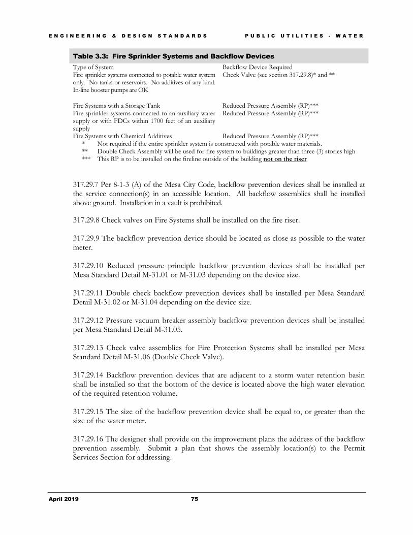
E N G I N E E R I N G & D E S I G N S T A N D A R D S P U B L I C U T I L I T I E S - W A T E R
April 2019 75
Table 3.3: Fire Sprinkler Systems and Backflow Devices Type of System Backflow Device Required Fire sprinkler systems connected to potable water system only. No tanks or reservoirs. No additives of any kind. In-line booster pumps are OK
Check Valve (see section 317.29.8)* and **
Fire Systems with a Storage Tank Reduced Pressure Assembly (RP)*** Fire sprinkler systems connected to an auxiliary water supply or with FDCs within 1700 feet of an auxiliary supply
Reduced Pressure Assembly (RP)***
Fire Systems with Chemical Additives Reduced Pressure Assembly (RP)*** * Not required if the entire sprinkler system is constructed with potable water materials. ** Double Check Assembly will be used for fire system to buildings greater than three (3) stories high *** This RP is to be installed on the fireline outside of the building not on the riser
317.29.7 Per 8-1-3 (A) of the Mesa City Code, backflow prevention devices shall be installed at the service connection(s) in an accessible location. All backflow assemblies shall be installed above ground. Installation in a vault is prohibited.
317.29.8 Check valves on Fire Systems shall be installed on the fire riser. 317.29.9 The backflow prevention device should be located as close as possible to the water meter. 317.29.10 Reduced pressure principle backflow prevention devices shall be installed per Mesa Standard Detail M-31.01 or M-31.03 depending on the device size. 317.29.11 Double check backflow prevention devices shall be installed per Mesa Standard Detail M-31.02 or M-31.04 depending on the device size. 317.29.12 Pressure vacuum breaker assembly backflow prevention devices shall be installed per Mesa Standard Detail M-31.05. 317.29.13 Check valve assemblies for Fire Protection Systems shall be installed per Mesa Standard Detail M-31.06 (Double Check Valve). 317.29.14 Backflow prevention devices that are adjacent to a storm water retention basin shall be installed so that the bottom of the device is located above the high water elevation of the required retention volume. 317.29.15 The size of the backflow prevention device shall be equal to, or greater than the size of the water meter. 317.29.16 The designer shall provide on the improvement plans the address of the backflow prevention assembly. Submit a plan that shows the assembly location(s) to the Permit Services Section for addressing.

E N G I N E E R I N G & D E S I G N S T A N D A R D S P U B L I C U T I L I T I E S - W A T E R
April 2019 76
317.30 Termination of Public Water Mains: The City requires the use of a curb stop and flushing pipe at the permanent or temporary terminus of all public water mains.
317.30.1 A minimum of one (1) pipe length is required beyond a fitting prior to the installation of the curb stop.
317.30.2 Curb stops with flushing pipe per M.A.G. Standard Detail 390 Type “A” may be used on projects where the termination is temporary, such as phased condominiums or townhouse projects.
317.30.3 Curb stops with flushing pipe per M.A.G. Standard Detail 390 Type “B” shall be used on projects where the termination is considered more or less permanent, such as at the boundary of a subdivision or at the end of the public water line within a street cul-de-sac.
317.31 Water Main Abandonment and Removal: Existing public water lines that have been abandoned either by the City of Mesa or utility provider that are adjacent to or within the boundaries of the proposed project are required to be removed in their entirety within the limits of the project. In general, abandoned waterlines located under paved roadways are allowed to remain in place.
317.31.1 Engineer, architect or designer shall identify the size; location and material of all abandoned waterlines & provide construction notes to the contractor regarding safe removal and disposal.
317.31.2 Removal and disposal of Asbestos Cement Pipe (ACP) shall be in accordance with the Policy Statement for Removal and Disposal of Asbestos Cement Pipe in the City of Mesa, Arizona; Revised September 29, 1999. Copies of this policy statement are available on the Engineering Division portion of the City of Mesa website at: http://www.mesaaz.gov/business/engineering/policies-forms
317.31.3 Water service lines that are to be abandoned shall have the corporation stop closed at the service saddle, and the service line shall be cut and capped or crimped within 12-inches of the connection to the main. Pressurized, abandoned sections of water service lines are not allowed to remain within City right-of-way or public easements.

D E S I G N C U S T O M I Z A T I O N
77
Figure 3.1 – City of Mesa Water Service/Planning Area

E N G I N E E R I N G & D E S I G N S T A N D A R D S P U B L I C U T I L I T I E S - W A S T E W A T E R
April 2019 78
Chapter 4 - Public Utilities - Wastewater Provides minimum design criteria and guidance regarding the preparation of construction documents for public wastewater collection facilities as an extension to the City of Mesa public utility system.
The purpose of this chapter is to present to the private land developer and any associated design professionals the standards to be used in designing a public wastewater collection system which is to be utilized by new or future land development within the City of Mesa. The intent of this chapter is to provide general guidance to the design professional and City staff during the plan preparation and plan review processes.
Section 401 - General Information
401.1 The City of Mesa owns and operates a public sanitary sewer system which is a master planned system comprised of a combination of collection mains, trunk sewer mains, force mains, lift stations and wastewater treatment facilities. Information regarding the existing system can be obtained from various City Departments or Divisions as outlined below.
401.2 Mesa’s system has been developed through a combination of Capital Improvement Projects (C.I.P.) and private land developments, which include subdivision or lot development as well as public utility main extensions. The majority of the wastewater collection system is located within the corporate boundaries of Mesa, but some components of the system are located within the jurisdictions of Maricopa County, the Town of Gilbert, and the Cities of Tempe and Phoenix.
401.3 The Water Resources Department of the City of Mesa is responsible for the operations and maintenance of the public sanitary sewer system. Questions regarding the operations of the public collection and treatment system should be directed to the office of the Assistant Director. To inquire further, please contact the Department at (480) 644-4444.
Chapter
4
T

E N G I N E E R I N G & D E S I G N S T A N D A R D S P U B L I C U T I L I T I E S - W A S T E W A T E R
April 2019 79
Section 402 - Wastewater Master Plans
402.1 The City of Mesa currently utilizes the 2018 Wastewater Master Plan Update prepared by Wastewater Engineers in Water Resources Department.
402.2 The current Wastewater Master Plan and associated exhibits can be reviewed at the Water Resources Department offices at 640 N. Mesa Drive.
Section 403 - Availability of City of Mesa Sewer
403.1 Questions pertaining to the availability of public sewer service from Mesa, system expansion, or extension requirements to serve proposed new projects shall be directed to Development Planning Section of the Development Services Department; PO Box 1466 Mesa AZ 85211-1466; (480) 644-3254.
Section 404 - City Code, Policies & Regulations
404.1 The design professional and/or the land developer should be aware of and become familiar with the following aspects of the various regulations that pertain to land development with the City of Mesa and its utility service area.
Section 405 - City Code
405.1 Title 9, Public Ways & Property contains information regarding the development of the public wastewater collection system in association with private land development. Chapter 6 of Title 9 pertains to land subdivision projects, while Chapter 8 deals with individual lot or parcel development (non-subdivision) projects. Chapter 4 of Title 8 has additional sanitary sewer regulations.
405.2 An electronic version of the City Code can be referred to on the City of Mesa website at: http://www.mesaaz.gov/city-hall/city-clerk/city-codes-laws-ordinances
Section 406 - City Ordinances
406.1 City ordinances stipulate the extension of public sanitary sewer mains across all public street frontages of the proposed project in order to facilitate the future extension of the public sanitary sewer collection system to serve other undeveloped frontages.
406.2 The Terms and Conditions for the Sale of Utilities Ordinance provides for and requires that in order to receive utility service from the City of Mesa, that all lands to receive utility service are developed in accordance with applicable regulations, standards and requirements.
406.3 An electronic version of the Terms and Conditions for the Sale of Utilities ordinance is located in the current Utility Rate Book available at:
https://www.mesaaz.gov/city-hall/office-of-management-budget/utility-rates
E N G I N E E R I N G & D E S I G N S T A N D A R D S P U B L I C U T I L I T I E S - W A S T E W A T E R
April 2019 80
Section 407 - City Policy
407.1 City policy stipulates that the developer of a project is responsible for any main line extensions necessary for the proposed project in accordance with the adopted Wastewater Master Plan in order to receive sewer service.
407.2 Policy also requires public sanitary sewer mains be extended to serve adjacent parcels which may also require the dedication of public rights-of-way or easements to serve the adjacent parcels.
407.3 Utility crossings of public streets are to be avoided. Open trenching (pavement cut) of public streets are not allowed for pavement less than five (5) years old. When the designer deems a utility must cross a public street, the designer shall provide an engineering evaluation that explains why alternatives to the crossing cannot be avoided.
Section 408 - Maricopa County Environmental Services Department (MCESD) 408.1 The developer and associated design professionals are expected to be aware of and comply with the regulations of the MCESD. See https://www.maricopa.gov/2618/Project-Approvals.
408.2 Maricopa County publishes the “Maricopa County Health Code”, portions of which regulate the construction of public sanitary sewer systems.
408.3 When stipulated by the Maricopa County Health Code for sewage systems including the installation of septic tank systems, provide a copy of the MCESD issued “Approval to Construct” Certificate.
408.4 Each Approval to Construct Certificate shall be followed up with an “Approval of Construction” Certificate that closes out the project after the system is completed. The developer is responsible for obtaining both approvals from MCESD prior to the City’s acceptance of the sewage system.
408.5 Maricopa County also requires a Sewer Service Agreement be executed by the City of Mesa for all industrial and residential subdivisions including condominiums and cemetery projects. See discussion below in the Sewer Service Agreement section for additional information.
Section 409 - Arizona Department of Environmental Quality (ADEQ) 409.1 ADEQ published Engineering Bulletin No. 11; Minimum Requirements for Design, Submission of Plans and Specifications of Sewage Works in 1978 when it was part of the Arizona Department of Health Services. The 1978 edition of Bulletin No. 11 is still in effect and the City of Mesa requirements meet or exceed the standards established by Bulletin No. 11, Chapter IV, Sewage Collection Systems.
Section 410 - EPA Regulations
410.1 The City has been required by the U.S. Department of Environmental Protection Agency (EPA) to develop, implement and maintain a program to control discharges that might harm the Publicly Owned

E N G I N E E R I N G & D E S I G N S T A N D A R D S P U B L I C U T I L I T I E S - W A S T E W A T E R
April 2019 81
Treatment Works (POTW). The program establishes local discharge limits for non-residential users and provides for a permitting process based on the user’s discharges and type of business.
410.2 In accordance with this regulation the City of Mesa has created an industrial wastewater pretreatment program. Additional information regarding this program can be found in Title 8, Chapter 4; Sanitary Sewer Regulations of the Mesa City Code.
Section 411 - Public Wastewater System Design
411.1 The following is the criteria for designing public sanitary sewer systems in the City of Mesa and its utility service area. Projected wastewater flows shall be based on the unit flows presented in Tables 4.1 and 4.2. Additional wastewater flows associated with manufacturing processes, central plants, or other uses not listed below must be identified and included in the design analysis. Peak wastewater flows shall be calculated using the peaking factors presented in Table 4.3.1 resential Wastewater Flows
Table 4.1 Residential Wastewater Flows
Land Use Categories Population Density Average Daily Use
Average Daily Flow
Low Density Residential (RR) 2.5 per dwelling unit (d.u.)
80 gallons per capita day (gpcd)
200 gallons per du
Low Density Residential (ER) 3.0 per d.u. 80 gpcd 240 gallons per du Medium Density Residential (LDR) 3.0 per d.u. 80 gpcd 240 gallons per du Medium Density Residential (LMDR) 3.2 per d.u. 80 gpcd 256 gallons per Medium Density Residential (MDR) 2.7 per d.u. 80 gpcd 216 gallons per du High Density Residential (MHDR) 2.0 per d.u. 80 gpcd 160 gallons per du High Density Residential (HDR) 1.7 per d.u. 80 gpcd 136 gallons per du Mixed Use/Residential (MUR) – Residential 1.7 per d.u. 80 gpcd 136 gallons per du
Table 4.2 Commercial and Industrial Wastewater Flows Land Use Categories Average Daily Flow
Commercial/Retail 0.5 gallons per day per square foot (gpd/sf) Office 0.4 gpd/sf Restaurant 1.2 gpd/sf Resort Hotel (includes Site Amenities) 380 gpd/room School without cafeteria 30 gpd/student Schools with cafeteria 50 gpd/student Cultural 0.1 gpd/sf
Table 4.3 Peaking Factors Average Flow (mgd) Existing Lines New Lines Less than 1.0 2.3 3 1.0 to 10 1.9 2.5 10 to 20 1.7 2.3 20 to 30 1.6 2.1 30 to 40 1.5 2 40 to 50 1.4 1.9

E N G I N E E R I N G & D E S I G N S T A N D A R D S P U B L I C U T I L I T I E S - W A S T E W A T E R
April 2019 82
Greater than 50 1.3 1.75
Source: City of Mesa Water Resources Department
Section 412 - Sewer Studies
412.1 Projects that are proposed in areas that were not included in the current Wastewater Master Plan or where the design assumptions were changed from the Master Plan will require a Basis of Design Report (BDR) to establish projected wastewater flows and assure that adequate capacity is available to serve the proposed project as well as the regional needs of the area. A BDR may also be required to demonstrate the conformance of individual phases of a development with the accepted master plan for that development.
412.2 As a minimum, wastewater studies or basis of design reports shall include the following:
• Summary of the planned development, including land use information; • Design parameters; • Existing conditions; • Projected Wastewater Flows; • Proposed conditions, including planned sewer line extensions; • Hydraulic analyses including Average Day and peak flows; and • Supporting exhibits, maps and modeling output as applicable. • Wet weather flow should account for 10-year, 24hr storm event flow.
412.3 A project-specific Wastewater Master Plan will be required for large developments or projects involving significant extensions of the public wastewater system. A hydraulic model analysis shall be included that demonstrates sufficient sewer capacities within the planned system under all flow conditions for all phases of development
Section 413 - Sewer Service Agreement
413.1 Developments are required to file a Sewer Service Agreement document with the Maricopa County Environmental Services Department. This Maricopa County form is initiated by the developer's engineer and executed by the City of Mesa Water Resources Department upon acceptance of the required design analysis and verification of the development’s impact on the existing collection system. Questions regarding the Sewer Service Agreement form should be directed to the Maricopa County Environmental Services Department.
Section 414 - Design Analysis
414.1 Projects involving land subdivision are required to provide a design analysis of their projects impact on the public sanitary sewer system. Utilizing the design criteria from Tables 4.1, 4.2, and 4.3, the registrant shall calculate the sewer flow of the proposed project. The resulting report shall be sealed and signed by the engineer and submitted to Development Services Department Development Planning Section along with copies of the sewer improvement plan sheets (email attachment

E N G I N E E R I N G & D E S I G N S T A N D A R D S P U B L I C U T I L I T I E S - W A S T E W A T E R
April 2019 83
preferred). Development Planning will forward the design analysis report to the Water Resources Department for their use in signing applicable MCESD form and in preparing a “Sewer Capacity Letter.”
Section 415 - Sewer Collection & Plant Capacity Adequacy 415.1 The City of Mesa Water Resources Department will issue a letter to Maricopa County Environmental Services Department acknowledging that Mesa has adequate capacity in the public sanitary sewer system to accommodate the proposed subdivision development if the review of the design analysis supports the addition of the proposed development to the current system. The developer or a designated representative shall submit the request for an acknowledgement letter to the Development Services Department Development Planning section as part of the Maricopa County form and design analysis submittal.
Section 416 - Standards, Specifications & Guidelines 416.1 Gravity vs. Pressurized Systems: All public sanitary sewer systems are to be of a gravity flow design unless other factors dictate the use of a lift station and force main. When conditions dictate the installation of a lift station, the City recommends that the lift station be regionally based in order to serve more than one development.
416.2 The City Engineer and Water Resources Department Manager will consider pressurized systems on a case-by-case basis. This consideration requires the presentation of the facts surrounding the request and the alternates available to the development.
416.3 Sanitary System Components:
416.3.1 Sewer Services: Sewer services, sometimes known as sewer laterals, are either 4" or 6" diameter pipe that serves existing or proposed buildings or structures.
416.3.2 Collector Mains: Collector mains are 8", 10", 12", 15" 18", 21" or 24" diameter pipe that serve as the primary means of collecting the sanitary sewerage throughout the City or it’s utility service area.
416.3.3. Transmission Sewer Mains: Mains 15" or larger are classified as transmission mains.
416.3.4 Trunk Sewer Mains: Trunk sewer mains are 30" diameter pipes or larger.
Section 417 - Private Sewer Utility Companies
417.1 Currently within the City of Mesa's Utility Service Area there are no private sewer utility companies.
417.2 Arizona Water Company: Developers and engineers are cautioned that a portion of the northeast area of the Utility Service Area is provided water service by the Arizona Water Company. Projects in this area require the establishment of a special billing arrangement with the City of Mesa Customer Service Division in order to receive sewer service from the City of Mesa.
E N G I N E E R I N G & D E S I G N S T A N D A R D S P U B L I C U T I L I T I E S - W A S T E W A T E R
April 2019 84
Section 418 - Sanitary Sewer Main Design
418.1 Location: Public sewer mains are required to be located within dedicated public rights-of-way (ROW) or easements (PUFE, PUE). See Chapter 1, General Requirements concerning the dedication of ROW or easements.
418.2 Horizontal Location: The standard locations for public sewer mains in public streets are five feet (5') south or west of the public street centerline unless otherwise approved by the City. Public sewer mains within easements are normally to be centered within a twenty-foot (20') Public Utility Easement or a twenty-foot (20') Public Utilities and Facilities Easement. When more than one public utility will occupy the easement, the public sewer main shall be offset five feet (5') from the centerline of the easement.
418.3 Easement Locations: The twenty-foot (20') public easements should generally be located or centered within a private drive or aisle of the proposed project. Installations under parking stalls, landscape areas, fences/walls, and overhangs shall be avoided unless an engineering evaluation of the necessity and feasibility is approved. Regardless of the easement width, buildings shall have sufficient setback from the sewer pipe such that buildings, building foundations or building slabs will not be undermined or damaged by a sewer main break or subsequent repair. Under the following circumstances, the engineer shall submit a structural/geotechnical analysis that verifies the integrity of the proposed structure under the condition of a sewer main failure, as well as verifying that the proposed structure and its foundations will not compromise the structural integrity of the sewer main:
• A sewer pipe and structure are separated by a horizontal distance less than or equal to the depth (invert) of the sewer pipe
• A sewer force main and structure are separated by a horizontal distance of 12’ or less
418.4 Easement Access: When a sewer line is located within an easement that is not within a paved roadway or other paved access way, an all-weather access road shall be provided to enable the City to access to the pipe, manholes, and other appurtenances for maintenance and repair. The access road shall have a minimum width of ten (10) feet and shall be paved or constructed of a minimum of six (6) inched of stabilized decomposed granite. Each end of the access road shall be connected to a public street, private access way, or turn-around easement conforming to City of Mesa requirements.
418.5 Raised Medians: Where a raised median divides a public street, the sewer main is to be offset from the median curb. While a minimum dimension for an offset has not been established, Mesa does require that the manhole ring or cover not encroach upon the median curb or gutter.
418.6 Retention Basins: Alignments within retention/detention basins shall be avoided. Where conditions dictate construction through a retention/detention area, special approval is required:
418.6.1 Civil engineer shall provide written justification for the alignment.
418.6.2 Civil engineer shall provide buoyancy calculations and special construction details and/or guidelines per manufacturer’s or design manual recommendations.
418.6.3 Any necessary manhole within a retention/detention basin shall have its rim above the high water elevation and shall be watertight.

E N G I N E E R I N G & D E S I G N S T A N D A R D S P U B L I C U T I L I T I E S - W A S T E W A T E R
April 2019 85
418.7 Vertical Location (Depth): The City requires a minimum cover of six feet (6') over the crown of the public sanitary sewer main as measured from surface course or finish grade. Cover of less than six (6) feet will be considered on a case-by-case basis and may be allowed if approved in writing by the Water Resources Department.
418.7.1 Trench Loading Calculations- The engineer shall provide load calculations upon request.
418.7.2 VCP shall be designed for loading per the “Clay Pipe Engineering Manual” based on a 1.5 minimum factor of safety.
418.7.3 Concrete pipe shall be designed for loading per the “Concrete Pipe Handbook” based on a 1.5 minimum factor of safety.
418.7.4 PVC, and HDPE pipe shall be designed for loading per the “Handbook of PVC Pipe, Design and Construction” and the “AASHTO Design Procedure for Thermoplastic Pipe”. The most stringent design requirements shall govern.
418.7.5 DIP shall be designed for loading per “Ductile Iron Pipe Research Association (DIPRA) Handbook”, latest edition.
418.8 Wash Crossings: Any sewer line that crosses a wash shall be encased in concrete in accordance with M.A.G. Std. Det. 404.
Section 419 - Velocity & Slopes 419.1 The City of Mesa requires that the velocity of flows within a public sewer main be in the range of two feet per second (2 fps) to nine feet (9 fps) based on the pipe running two thirds (2/3) full.
419.1.1 The minimum velocity of 2.0 fps provides for an adequate velocity within the conduit to scour the conduit walls of any built up solids.
419.1.2 The maximum velocity of 9.0 fps ensures that the pipe material is not affected and turbulence is minimized.
Section 420 - Sizing 420.1 Master Plan: Typically, sizing of public sewer mains is to be per the most recent Mesa Waste Water Master Plan. However, where the master plan does not address the area of the proposed project, a sanitary sewer study or in the case of a large development, a master plan shall be developed in accordance with Sewer Studies section above.
420.2 Minimum Size: The minimum size of a public sewer main is eight inches (8") in diameter. Pipes shall be sized to carry the projected peak dry-weather flow at build-out, based on the peaking factors presented in Table 4.2, with the pipe flowing 2/3 full.
420.3 Future & Regional Needs: Public sanitary sewer mains shall be sized to satisfy the needs of the proposed development taking into account the future needs of the adjacent properties as well as the regional needs of the service area. Sewer mains designed for future flows are subject to hydrogen sulfide

E N G I N E E R I N G & D E S I G N S T A N D A R D S P U B L I C U T I L I T I E S - W A S T E W A T E R
April 2019 86
generation and odor complaints during early phases of development if flowing at low percentages of design flows. The design engineer shall include provisions to mitigate these issues when possible.
Section 421 - Materials 421.1 The following materials are acceptable:
421.2 Rigid Pipe Material:
421.2.1 Vitrified Clay Pipe (VCP): shall conform to Section 743 of the M.A.G. Uniform Standard Specifications as amended by the City of Mesa.
421.2.1.1 VCP exceeding thirty-inches (30") in diameter requires special bedding treatment and shall be detailed on the construction plans.
421.2.2 Ductile Iron Pipe (DIP) with ceramic epoxy lining only when approved by the Water Resources Department.
421.2.3 Rubber Gasket Reinforced Concrete Pipe (RGRCP) with a PVC lining: shall conform to Sections 735 and 741 of the M.A.G. Uniform Standard Specifications as amended by the City of Mesa.
421.2.3.1 RGRCP pipe is approved for constructing public sewer mains twenty-inches (20") or larger in diameter.
421.3 Flexible Pipe Material:
421.3.1 Polyvinyl Chloride (PVC) pipe: shall conform to Section 745 of the M.A.G. Uniform Standard Specifications as amended by the City of Mesa.
421.3.1.1 PVC pipe is approved for public sewer mains eight inches (8") through eighteen inches (18") diameters only.
421.3.1.1 The use of eighteen inch (18") PVC will require that granular bedding (ABC) shall be installed and compacted to one foot (1') above the pipe.
421.3.1.2 The installation of PVC sewer mains in excess of eighteen inch (18") diameter will be considered on a case-by-case basis. The engineer shall provide a comprehensive report that provides the justification for the installation of the larger diameter PVC main(s).
421.3.2 HDPE or PE Pipe: The installation of HDPE or PE pipe will be considered on a case-by-case basis. The engineer shall provide a comprehensive report that provides the justification for the pipe material.
421.3.2.1 Where approved, the installation of High Density Polyethylene (HDPE) or Polyethylene (PE) shall conform to Section 738 of the M.A.G. Uniform Standard Specifications as amended by the City of Mesa.

E N G I N E E R I N G & D E S I G N S T A N D A R D S P U B L I C U T I L I T I E S - W A S T E W A T E R
April 2019 87
Section 422 - Minimum Separations (Extra Protection) 422.1 In order to protect the public water supply from contamination, the engineer shall maintain separation distances in accordance with the following:
422.2 The Maricopa County Health Code, Arizona Department of Environmental Quality Engineering Bulletin 10 and M.A.G. Standard Details 404–1, 404–2, and 404-3; Water and Sanitary Sewer Separation/Protection.
422.3 Subordinate for Quality: Mains conveying a higher quality of water shall be located above mains conveying a lower quality of water unless otherwise protected.
422.4 Minimum Separations: Minimum separations between potable water mains and sanitary sewer mains shall be:
422.4.1 Six foot (6') horizontal as measured from the outside of pipes
422.4.2 Two foot (2') Vertical as measured from the outside of pipes
422.4.3 Sanitary sewers shall be located a minimum of five (5) feet horizontally from the base of any trees.
422.4.4 Sanitary sewers shall be located a minimum of six (6) feet horizontally and two (2) feet vertically from any storm drain.
422.5 Separation from Manholes: Minimum Separation between potable water mains and a sanitary sewer manhole shall be:
422.5.1 Six foot (6') horizontal as measured from the center of the manhole and the outside of the water main.
422.6 Services: Individual house services or building plumbing shall conform to the latest Plumbing Code adopted by the City of Mesa. Service lines shall be located at their point of connection to the sewer main and at the property line with electronic markers in accordance with M.A.G. Standard Detail 440-1,2 or 3.
Existing wastewater mains shall be kept in service as individual services are added. (example) Fabco service tap or approved equal. (see Approved Products List http://mesaaz.gov/business/engineering/approve-products-equipment-natural-gas-line-contractors )
Section 423 - Intersecting Sewer Mains 423.1 All points of intersection require the installation of a sewer manhole in accordance with Sanitary Sewer Appurtenances – Manholes section below.
423.2 Angle intersections less than ninety degrees (90°) (i.e., acute angles) in the direction of the flow are prohibited.
423.3 Where the diameters of the intersecting mains are different, the crowns of the mains shall be equal unless otherwise directed by the City.

E N G I N E E R I N G & D E S I G N S T A N D A R D S P U B L I C U T I L I T I E S - W A S T E W A T E R
April 2019 88
423.4 Normal invert elevation changes at a manhole shall be in the range of one tenth to two tenths (0.10’ – 0.20’).
423.5 There shall be a one tenth of a foot (0.10') drop in elevation in the invert elevations where the deflection of the intersecting mains exceeds forty-five degrees (45°).
423.6 Elevation changes of up to two and a half feet (2.5’) may be allowed without the use of a drop structure where justified by the civil engineer due to conflicts or special conditions.
Section 424 - Trench Crossings 424.1 Trench crossings where the public sewer main will be more than four feet (4') above the bottom of the trench to be crossed shall be supported in accordance with M.A.G. Standard Detail 403-1, 403-2, and 403-3 to prevent shear failures from excessive trench settling. The use of ductile iron pipe in lieu of pipe supports will not be allowed unless specifically approved in writing by the Water Resources Department.
424.2 Trench Backfill & Pavement Replacement: The contractor is responsible for backfilling and replacing pavement in all public street excavations per the City of Mesa Standard Detail M-19.04.1 and the Policy Statement for Street Trench Backfilling and Pavement Replacement, revised September 29, 1999. Copies of the Policy Statement are available online from the Engineering Department web pages at: http://www.mesaaz.gov/home/showdocument?id=12294
Section 425 - Main Stubs 425.1 Sewer main extensions that are adjacent to vacant or developable parcels are required to install mainline stubs at the adjoining manhole(s) to facilitate the future extension of the public sewer system to serve future developments. Stubs are to be five feet (5') long minimum and eight inches (8") minimum diameter.
Section 426 - Force Mains 426.1 Approval to Use: Proposed private or public sewer force mains to serve a proposed land development project will be reviewed and approved on case-by-case basis by the City Engineer and Water Resources Department Manager.
426.2 Force Mains are not available for connection of other public sewer main extensions or the installation of sanitary sewer services to serve adjacent properties.
426.3 Design Criteria:
426.3.1 Velocity Requirements: Velocity of the flow within the force main shall be between 4 and 6 fps unless otherwise approved by the City.
426.3.2 Material: All types of pipe material used shall have established ASTM, ANSI, AWWA and NSF standards of manufacture or seals of approval and shall be designated as pressure sewer pipe. Private force main located within City of Mesa right-of-way shall be ceramic epoxy-lined-ductile iron pipe.
E N G I N E E R I N G & D E S I G N S T A N D A R D S P U B L I C U T I L I T I E S - W A S T E W A T E R
April 2019 89
426.3.3 Air Release Valves: Air/Vacuum relief is required at all peaks in elevation and where required to mitigate transient pressures as determined by a surge analysis. Sewer-rated air relief valves are required.
426.3.4 Cleanouts: Two-way cleanouts shall be installed every eight hundred feet (800') or one-way cleanouts may be installed every four hundred feet (400').
426.3.5 Pressure Test: Prior to approval to operate the force main, the force main shall be pressure tested in accordance with M.A.G. Uniform Standard Specifications 615.10, which requires hydrostatic tests in accordance with M.A.G. 610.14.
426.3.6 Identification: All force mains require the placement of a marking tape identifying the purpose of the force main within one foot (1') of the top of the main.
426.3.7 Depth and Cover: Force mains shall be designed to absorb superimposed live loads and the backfill overburden without damage to either the pipe material or the hydraulic function of the force main. The engineer shall address and identify the minimum depth of cover to be provided during the force main construction.
Section 427 - Curvilinear Sewers 427.1 The installations of new curvilinear sewer mains for public sanitary sewer collection systems are not permitted within the City of Mesa utility service area.
Section 428 - Septic Systems 428.1 Projects that receive approval for a septic disposal system may still be required to install a dry sewer system (see below).
Section 429 - Dry Sanitary Sewer Systems (Unconnected) 429.1 Dry sewer systems are essentially public sewer systems that are installed in advance of a planned public main extension that would provide a point of outfall to the system. These systems where required shall be designed in accordance with the above sections for public sewer mains and shall provide a design that facilitates the conversion from the septic disposal system(s) to the public sanitary sewer system.
Section 430 - Structure Crossings 430.1 Where a proposed sanitary sewer main will cross underneath an existing structure such as a box culvert, the sanitary sewer main shall be:
430.1.1 Constructed of Ductile Iron Pipe (DIP) with ceramic epoxy lining. Minimum pipe class shall be 350 psi unless otherwise approved by the City.
430.1.2 Two feet (2') of clearance is required between the bottom of the structure and the outside top of the sewer main.

E N G I N E E R I N G & D E S I G N S T A N D A R D S P U B L I C U T I L I T I E S - W A S T E W A T E R
April 2019 90
430.1.3 In lieu of two feet (2') of clearance, the sewer main may be encased in 6" of Class “C” concrete.
430.1.4 A casing or a carrier pipe may be utilized.
Section 431 - Pipe Casings 431.1 Pipe Casing for public sanitary sewer mains shall be designed and constructed in accordance with the M.A.G. Uniform Standard Specification Section 602. Design engineer shall provide calculations, details and specifications for review.
Section 432 - Private Sewer Lines 432.1 Projects that will develop a private sewer collection system shall comply with the requirements of the Maricopa County Environmental Services Department, the current edition of the Plumbing Code adopted by the City of Mesa, and City of Mesa Terms and Conditions for the Sale of Utilities.
432.2 Projects constructing a private sewer collection system independent of any on-site private structures are required to obtain a plumbing permit from the Development Services Department Permits Section.
432.3 Private sewer collection systems that connect to the City of Mesa public sewer system shall make the connection at an existing manhole stub or shall construct a new manhole.
432.4 Private sewer systems cannot be located within Public Rights-Of-Way or Easements.
432.5 Perpendicular crossings of Public Easements by private sewer lines will be considered on a case-by-case basis.
Section 433 - Sanitary Sewer Appurtenances 433.1 Manholes: Standard manholes on the City of Mesa public sewer system shall conform to M.A.G. Standard Details 420-1, 420-2, and 420-3 and the following:
433.1.1 Five foot (5') in diameter with a thirty inch (30") frame & cover, Type ‘A” Top
433.1.2 No steps shall be installed in the manhole
433.2 Manhole Spacing on public sewer mains shall comply with the following Table 4.3:
433.3 Manhole frames & covers shall not be located within public sidewalks, driveways, curbs, or gutters.
Table 4.4 Manhole Spacing Pipe Size (Inches) Maximum Spacing (Feet) 8" to 15" 500' 18" to 30" 600' 36" to 60" 800' Over 60" 1,300' Source: ADEQ Engineering Bulletin No. 11

E N G I N E E R I N G & D E S I G N S T A N D A R D S P U B L I C U T I L I T I E S - W A S T E W A T E R
April 2019 91
433.4 Corrosion Protection: Manholes on sewer lines 15” and larger and at force main discharge locations are required to have a form of corrosion protection. Visit the City of Mesa Engineering Department webpage for the current list of approved coating systems, at https://www.mesaaz.gov/business/engineering/approve-products-equipment-natural-gas-line-contractors
433.5 The approved coating system shall be applied to all exposed internal concrete, brick, and mortar surfaces including the bench, bench-to-pipe transitions, unlined concrete pipes within the manhole, risers, cones, and adjusting rings. The coating on the bench shall extend into the flow channel, down to the liquid surface. Coating of the metallic manhole frame and cover shall not be required.
433.5.1 Spark testing and adhesion testing of the applied coating system that is performed in accordance with City of Mesa specifications shall be required for all sewer manholes and structures that are coated with a corrosion protective coating. Visit http://www.mesaaz.gov/home/showdocument?id=3256 for the required specification.
433.6 Drop Manholes: Drop manholes are to be avoided due to the increased maintenance issues (hazards to personnel that must enter them, generation of odors due to the turbulence of the flow, etc…) associated with their use.
433.7 Approval to Use: The City of Mesa shall determine when the use of drop manhole structure(s) is appropriate. When specifically approved by the City of Mesa, the engineer may employ drop manhole structures in conformance with the following:
433.7.1 Where changes in elevation between adjoining manholes is two and one-half (2.5) feet or less, the grade shall be adjusted to eliminate the drop, unless it can be demonstrated that such an adjustment is not feasible.
433.7. 2 Changes in elevations between two and one-half feet (2.5') and five feet (5') shall utilize a Drop Sewer Connection per M.A.G. Standard Detail 426 Type “A”.
433.7. 3 Elevation changes in excess of five feet (5') require the use of a M.A.G. 426 “Type B” drop.
433.8 Water Tight Manholes: Watertight manholes shall be used in those locations where the public sewer system may be subject to flooding, as determined by the City. Watertight manholes shall conform to M.A.G. Standard Details 420-1, 420-2, 420-3, and 424-2. Water tight frame & cover shall be installed at force main discharge manholes to prevent odor emissions.
433.8.1 Five foot (5') in diameter with a 30" frame & cover
433.8.2 No steps shall be installed in the manhole
433.9 Cleanouts: Cleanouts are to be constructed in accordance with M.A.G. Standard Detail 441. Cleanouts may be used in place of a manhole at the end of an eight inch (8") main that is less than two hundred feet (200') in length. Cleanouts may be constructed using SDR 35 PVC in lieu of VCP as shown in MAG Detail 441.

E N G I N E E R I N G & D E S I G N S T A N D A R D S P U B L I C U T I L I T I E S - W A S T E W A T E R
April 2019 92
433.10 Sewer Services:
433.10.1 Sewer services are to be installed per M.A.G. Standard Detail 440.
433.10.2 Sewer services shall not be installed in manholes unless approved by the City Engineer
433.10.3 Connections to the mains shall be made utilizing single wyes.
433.10.4 Double wyes are not permitted.
433.11 Sanitary sewer services shall be designed to pass below existing or proposed public water mains with a minimum clearance of 6-inches (6") between the sewer service and the public water main.
433.12 Plugs: Plugs shall be installed per M.A.G. Standard Detail 427.
433.13 Lift Stations: Where approved, sewage lift stations shall be designed and constructed in accordance with the Sewage Pump Station requirements as published in the Arizona Administrative Code Title 18, Chapter 9 and, if private, the latest adopted edition of the Plumbing Code.
433.14 Private lift stations are not permitted to be located within dedicated public rights-of-way or public easements.

E N G I N E E R I N G & D E S I G N S T A N D A R D S
April 2019 93
Chapter 5 - Public Utilities – Natural Gas Provides minimum design criteria and guidance regarding the preparation of construction documents for public natural gas system facilities as an extension to the City of Mesa public utility system.
he purpose of this chapter is to present to those design professionals involved in a private land development project or city project that involves the City’s natural gas utility system general information regarding the processes that are required during the construction document preparation, plan review, approval and permitting stages of land development.
Section 501 - General Information 501.1 The City of Mesa owns and operates a public natural gas utility. There are two natural gas providers within the City of Mesa’s boundaries, City of Mesa Energy Resources Department and Southwest Gas. The City of Mesa Energy Resources Department also maintains and operates gas distribution in Pinal County – Magma/Queen Creek areas. Figure 5.1 (Page 87) shows the limits of the natural gas service areas. In addition, there are a limited number of areas, primarily on City of Mesa borders, where the Energy Resource Department’s service does extend into Chandler, Gilbert and to the north on Indian Reservation areas. Information regarding the Energy Resource Department’s system can be obtained from various City Departments or Divisions as outlined below. Additional information is also available on the Energy Resource Department’s website: http://www.mesaaz.gov/residents/energy-resources/natural-gas
501.2 The Energy Resource Department’s system has been developed through a combination of Capital Improvement Projects (C.I.P.) and private land developments, which include subdivision or lot development as well as public utility main extensions. The majority of the system is within the corporate boundaries of Mesa but some components of the system are located within the jurisdiction of Maricopa and Pinal Counties.
501.3 The Energy Resources Department is responsible for the operations and maintenance of the public natural gas utility system. Questions regarding the operations of the natural gas system should be directed to the office of the Energy Resources Department Director (480) 644-2273.
Chapter
5
T

E N G I N E E R I N G & D E S I G N S T A N D A R D S P U B L I C U T I L I T I E S – N A T U R A L G A S
April 2019 94
Section 502 - Availability of City of Mesa Natural Gas Service
502.1 Questions regarding the availability of service, the expansion of the natural gas system or extension requirements to serve proposed new developments should be directed to one of the Energy Resources Department’s business development representatives at (480) 644-3683, (480) 644-2652, or (480) 644-2156. Gas design inquiries should be directed to the Gas Engineering Section of the Engineering Department (480) 644-2509.
Section 503 - City Code, Policies & Regulations
503.1 The design professional should be aware of and become familiar with the following aspects of the various regulations that pertain to land development within the City of Mesa and its natural gas service territory.
503.2 City Code: The “Terms and Conditions for the Sale of Utilities” is adopted by public ordinance. It is important that the design professional familiarize themselves with the most current ordinance, rates, service requirements, and authorities to connect, disconnect and terminate services.
503.3 City Policy: City policy stipulates that the City of Mesa Engineering Department will perform and provide the engineering design for all new or relocated natural gas facilities in the Energy Resource Department’s natural gas service territory.
503.4 City policy also stipulates that City of Mesa Energy Resource Department crews or a designated pipeline contractor shall perform all work involving the City of Mesa natural gas system.
503.5 Utility crossings of public streets are to be avoided. Open trenching (pavement cut) of public streets are not allowed for pavement less than five (5) years old. When the designer deems a utility must cross a public street, the designer shall provide an engineering evaluation that explains why alternatives to the crossing cannot be avoided.
Section 504 - Natural Gas System Design
504.1 Design Standards, Specifications & Guidelines: The Gas Engineering section of the Engineering Department has oversight of the design of City’s natural gas infrastructure. The designer is required to submit the design plans for the natural gas system for the proposed development, separate from and in advance of the permitting submittal, to Gas Engineering for review and redlining. The designer is required to incorporate the redlined design into the improvement plans. The Senior Gas Engineer for the City of Mesa will stamp and seal the natural gas system portion of the design on the record PDF to be provided to the City. The Senior Gas Engineer will also assure, through a quality control review that all construction notes and references are included prior to affixing the seal.
504.2 Trench Backfill & Pavement Replacement: The contractor is responsible for backfilling and replacing pavement in all public street excavations per the City of Mesa Standard Detail M-19.04.1 and the Policy Statement for Street Trench Backfilling and Pavement Replacement, revised September 29, 1999. Copies of the Policy Statement are available online from the Engineering Department web pages at: http://www.mesaaz.gov/business/engineering/policies-forms

E N G I N E E R I N G & D E S I G N S T A N D A R D S P U B L I C U T I L I T I E S – N A T U R A L G A S
April 2019 95
504.3 Natural Gas Mains:
504.3.1 Location: Gas mains and service lines are usually installed in conjunction with public water line trench and require a minimum cover of 30-inches over the top of natural gas lines, per Mesa Standard Detail M-58. Separation requirements from “other” utilities are identified in Mesa Standard Detail M-60.
504.3.2 Sizing: Sizing is per the Engineering Department and/or the Energy Resources Department.
504.3.3 Materials: Materials for the City of Mesa Natural Gas System are provided by the Energy Resources Department and installed by Energy Resources or a designated pipeline contractor.
504.4 Natural Gas Services: Similar to gas mains, natural gas services are owned, operated and installed by the Energy Resources Department. Installation of residential service lines will also utilize a “joint-trench” concept according to gas detail CP-22.1. Commercial installation will utilize joint-trench opportunities where practical and/or feasible, utilizing either M-58 or CP-22.1. Requirements for the placement of the meter, on property either residential or commercial, will adhere to the plumbing code and applicable Gas Utilities Operations and Maintenance Manual. Copies of these details are available through the Gas Engineering office.
504.5 “Check and Wrap” General Note Required on All Plans: The following general note shall be included on all plan sets that involve underground excavation work regardless of whether gas work is part of the project scope or not, “When gas main and/or services are exposed, contact the City of Mesa at 480-644-2261 for inspection of the exposed pipe and coating prior to backfilling the trench.”

E N G I N E E R I N G & D E S I G N S T A N D A R D S P U B L I C U T I L I T I E S – N A T U R A L G A S
April 2019 96
Figure 5.1: Natural Gas Service Areas
E N G I N E E R I N G & D E S I G N S T A N D A R D S
April 2019 97
Chapter 6 - Public Utilities – City Electric Provides minimum design criteria and guidance regarding the preparation of construction documents involving connection to the City of Mesa electric system.
he purpose of this chapter is to present to those design professionals involved in a private land development project and city project that involves the City’s electric utility system general information regarding the processes that are required during the construction document preparation, plan review, approval and permitting stages of land development.
Section 601 - General Information 601.1 The City of Mesa owns and operates a public electric utility, which is one of two public utilities that provide electrical service to Mesa residents. Figure 6.1 shows the limits of the City of Mesa Electric Service Area. Information regarding the City of Mesa system can be obtained from various City Departments or Divisions as outlined below. The other public utility providing electric service is Salt River Project.
601.2 The Chandler brothers developed the City of Mesa electric utility system in the late 1800’s and early 1900’s. Mesa purchased the utility in 1917 and the Arizona Supreme Court determined the service area in 1954. Unlike the other City of Mesa utilities, developers are not responsible for installing the electric infrastructure. The service area for the City’s electric utility is approximately five and one-half square miles in the heart of the City; the service area is delineated on Figure 6.1, Electric Service Area.
601.3 The Energy Resources Department of the City of Mesa is responsible for the operations and maintenance of the electric utility system. Questions regarding the operations of the electric utility should be directed to the office of the Energy Resources Engineer (480) 644-2264.
601.4 Electric utility service is available to both residential and commercial projects.
601.5 The Electric Utility is located in the Utilities Building at 640 N. Mesa Drive.
Section 602 - City Code, Policies & Regulations
602.1 The design professional should be aware of and become familiar with the following aspects of the various regulations that pertain to land development within the City of Mesa and its utility service areas.
Chapter
6
T
E N G I N E E R I N G & D E S I G N S T A N D A R D S P U B L I C U T I L I T I E S – C I T Y E L E C T R I C
April 2019 98
Section 603 - City Policy
603.1 Contact for Service: The developer or an appropriate representative (i.e., architect, engineer, etc.) is required to contact the City of Mesa Electric Utility to arrange electric utility service and obtain utility requirements for the proposed project when it is located within the City of Mesa electric service area. This contact is separate from planning and building permit process submittals. However, the developer is responsible to incorporate electric utility service requirements into their plans that will be submitted for permitting. The Electric Utility is responsible for the design and installation of utility infrastructure needed to bring service to the development. Therefore, the developer is advised to contact the Electric Utility early in project development to help avoid delays in permitting or service connection.
603.2 Electric Code: The City of Mesa Electric Utility requires developers to comply with the currently adopted edition of the National Electric Code as modified by the City of Mesa.
603.3 Service, Voltage & Meters: Service to the customer will be provided from City lines of sufficient capacity to provide adequate service at the voltage available. The City will determine the location of the service entrance section and electric meter within its service area.
603.4 De-energization: The developer or contractor is required to contact the Electric Utility when it is necessary to de-energize the electric service. Only authorized City of Mesa Electric Utility personnel are to open, break seals, move, relocate or replace meters and other electric utility equipment owned by the City.
603.5 Right-Of-Way & Easements: The developer is responsible to provide any rights-of-way or public utility easements, including documentation suitable for recording, necessary to serve the proposed project.
603.6 Street Crossings: Utility crossings of public streets are to be avoided, whether overhead or underground. Open trenching (pavement cut) of public streets are not allowed for pavement less than five (5) years old. When the designer deems a utility must cross a public street, the designer shall provide an engineering evaluation that explains why alternatives to the crossing cannot be avoided.
Section 604 - Electric Service Design
604.1 Proposed Plans: The developer or an appropriate representative shall provide to the Electric Utility copies of the construction plans for the proposed project as early as possible, to avoid plan check conflicts and delays in design and construction.
604.2 The submittal shall include drawings or plans that are of a sufficient scale to determine the location of the service entrance section and metering equipment on the building(s) and the “point of service” on the City of Mesa Electric Utility system.
604.2.1 The submittal shall include the electrical plans, public utility improvement plans, site plans, schematic diagrams and electrical load calculations.
604.3 Location: All new electric services and service changes, modifications or upgrades must be located underground.

E N G I N E E R I N G & D E S I G N S T A N D A R D S P U B L I C U T I L I T I E S – C I T Y E L E C T R I C
April 2019 99
604.4 Voltage and Amperage: Service voltages and amperage sizes that are readily available within the City of Mesa Electric Utility service area are:
Project Type Standard Voltages Range of Service Size (Amps) Residential 120/240V 1P3W
120/208 1P3W
100 – 200A Self-contained meter Above 200A CT Rated with meter test provisions
Commercial
120/240V 1P3W 100-600A 208GrdY/120V 3P4W 480GrdY/277V 3P4W 240D or 480D 3P3W
100-3,000A 100-3,000A Obsolete – For Reference Only
Other service voltages and amperages may be available but must be approved by the electric utility and may result in delays and added service charges for special order transformers and metering equipment. Contact the Energy Resources Engineer to coordinate availability of service sizes and voltages.
604.5 The Electric Utility will furnish the available short circuit current (AIC) upon request.
604.6 Developer’s Responsibility: The developer is responsible to furnish all material not provided by the Electric Utility and for complete installation of the electric service from the “point of service” to the service entrance section (SES) as determined by the Electric Utility. Service facilities provided by the developer shall be furnished and installed in accordance with design drawings prepared, approved and inspected by the Electric Utility. The developer shall pay all applicable construction costs and fees prior to the electric utility scheduling service construction and connection. The developer shall submit supplier drawings, referencing EUSERC requirements, and shall obtain electric utility approval for all CT rated and multiple meter service entrance sections, prior to SES fabrication and installation. Approval drawings shall be submitted, preferably directly from the supplier, to the Energy Resources Electric Meter Shop Supervisor. 604.7 City’s Responsibility: The City of Mesa Electric Utility will provide electric utility plans, will provide inspection of developer installed facilities, and will furnish and install the primary conduit(s), the primary conductor, the transformer, the pad mounted transformer (i.e., “point of service”), test switches and the electric watt-hour meter.
604.8 The City of Mesa Electric Utility will review, provide comment on and ultimately approve the electrical service design to all proposed projects within the City’s electric service area.
604.9 Trench Backfill & Pavement Replacement: The contractor is responsible for backfilling and replacing pavement in all public street excavations per the City of Mesa Standard Detail M-19.04.1 and the Policy Statement for Street Trench Backfilling and Pavement Replacement, revised September 29, 1999. Copies of the Policy Statement are available online from the Engineering Department web pages at: http://www.mesaaz.gov/business/engineering/policies-forms
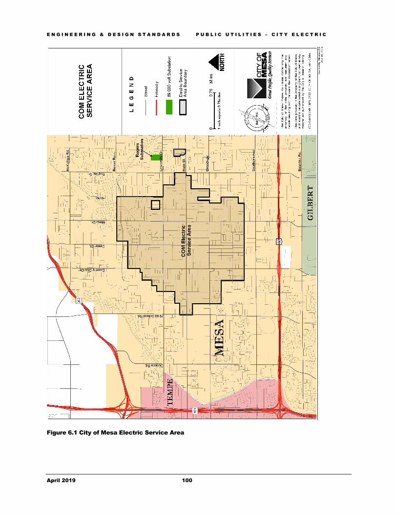
E N G I N E E R I N G & D E S I G N S T A N D A R D S P U B L I C U T I L I T I E S – C I T Y E L E C T R I C
April 2019 100
Figure 6.1 City of Mesa Electric Service Area

E N G I N E E R I N G & D E S I G N S T A N D A R D S
April 2019 101
Chapter 7 - Public Utilities – Non-City Utilities The purpose of this chapter is to provide guidance for working in the City’s Right-Of-Way and public utility easements. It provides minimum design criteria and guidance regarding the preparation of construction documents..
he purpose of this chapter is to present to those design professionals involved in a private land development project and city project which involves the other public utilities or City franchisee’s that provide utility service to land development projects, general information regarding the processes that are required during the construction document preparation, plan review, approval and permitting stages of land development.
Section 701 - General Information
701.1 Definition: Non-City utilities are those companies, corporations, or entities that provide some type of utility service, whether it is electricity, telecommunications, water, or information services that are not owned, operated or generated by the City of Mesa. Within the City of Mesa, Non-City utilities are provided by but not limited to the following companies or utilities: AGL Networks, Air Products, Arizona Water Company, AT&T, Cox Communications, CenturyLink, Roosevelt Water Conservation District, Salt River Project, Southwest Gas Corporation, Williams Communications, and Zayo Group.
701.2 Placement in Right-Of-Way & Easements: Utility companies that are recognized as a public utility or have been granted a franchise or license by the City Council to serve the citizens of Mesa are allowed to place facilities within the dedicated City’s rights-of-way and public easements subject to the permit review and approval of the City of Mesa. All other private facilities are prohibited from utilizing the public rights-of-way and public easements without an executed license or franchise agreement, and an encroachment permit.
701.3 Permit Required: Projects where the (re)developer’s contractor(s) will be installing facilities (i.e., conduit) for the use of the Non-City Utilities are required to obtain a separate Right-Of-Way Permit.
701.3.1 A contractor with the appropriate license and current Certificate of Insurance on file may obtain this permit from the Permit Services Section of the Development Services Department .
Chapter
7
T

E N G I N E E R I N G & D E S I G N S T A N D A R D S P U B L I C U T I L I T I E S – N 0 N - C I T Y
April 2019 102
Section 702 - Availability of Non-City Utilities
7032.1 Questions regarding the products, services, operations and processes of the various utility providers should be directed to the individual utility companies.
Section 703 - City Code, Policies & Regulations 703.1 Land development requires the installation and/or construction of both City-provided and Non-City utilities in order to complete the necessary infrastructure for the proposed project.
703.2 The City of Mesa administers all utility planning, permitting, maintenance, and construction processes in accordance with the Maricopa Association of Governments (M.A.G.) Uniform Standard Specifications, the City of Mesa Supplement to the M.A.G., City Code, National Electrical Safety Code (NESC), National Electrical Code (NEC), City of Mesa Construction Materials Field Testing Handbook, and the Arizona Utility Coordinating Committee (AUCC) Public Improvement Project Guide.
703.3 Regulates Use of Right-Of-Way & Easements: In order to prevent or reduce utility conflicts between the City utilities and those provided by other companies, the City of Mesa has adopted ordinances and standards to regulate the use of the public rights-of-way, which includes dedicated right-of-way for public streets as well as the public utilities and facilities easements (PUFE) and public utility easements (PUE).
703.4 The design professional and the Non-City Utility providers should be aware of and become familiar with the various regulations that pertain to land development within the City of Mesa and its utility service areas.
703.5 Mesa City Code Title 9, Public Ways & Property contains information regarding the regulation of public right-of-way and public easements in association with private land development. Chapter 1 of Title 9 pertains to Right-Of-Way Permits, while Chapter 6 deals with requirements to provide right-of-way or easements in conjunction with land subdivision.
703.6 An electronic version of the City Code may be referenced on the City of Mesa website at: http://www.mesaaz.gov/clerk/
Section 704 - City Ordinances
704.1 City ordinances provide for and require that all private land developments in the City of Mesa be developed, operated and maintained in accordance with applicable regulations, standards and requirements.
704.2 Telecommunications: Any telecommunications corporation seeking to install, maintain, construct, or operate telecommunications facilities in the City of Mesa’s right-of-way and public utility easements, or provide telecommunication service by means of such facilities, must first be granted a license by the City of Mesa under Title 9, Chapter 14, of the Mesa City Code. For additional information regarding the process to obtain a Telecommunications Franchise License, please contact the Right of Way Manager in the Engineering Department at 480-644-2251.

E N G I N E E R I N G & D E S I G N S T A N D A R D S P U B L I C U T I L I T I E S – N 0 N - C I T Y
April 2019 103
704.3 Joint Trench: The City of Mesa requires right of way users (e.g. telecommunications providers) to utilize a common or joint trench with other non-City utilities where a (re)developer or utility company provides a trench for undergrounding of non-City utilities.
704.4 Pavement Cuts: Mesa City Code requires all pavement cut activities to have an approved permit and be restored in accordance with City standards and specifications. Title 9, Chapter 1 of the code requires a pavement restoration fee for cutting pavement that is newer than five years old and prohibits pavement cuts, except under certain limited conditions, for pavement two years old or less. The City has established a pavement cut rate structure based on pavement age and size of cut. Pavement cuts include potholes, pavement damage, trenching, etc.
Section 705 – City Policy 705.1 Coordination Required: The City of Mesa requires that Non-City Utility providers coordinate the location of their Non-City utilities/facilities for projects that have private streets or drive areas and will have public utilities on-site in public easements.
705.2 Conflict Review Required: It is standard practice to perform a conflict review of the Non-City Utility provider’s construction plans for improvements, facilities or structures to be constructed or located within City of Mesa public rights-of-way or public easements to ensure that the integrity of the City utilities and the public rights-of-way are maintained. The conflict review is performed as part of the review of the non-City utilities permit application.
705.3 Utility Crossings: Utility crossings of public streets are to be avoided, whether overhead or underground. Open trenching (pavement cut) of public streets are discouraged for pavement less than five (5) years old. When the designer deems a utility must cross a public street, the designer shall provide an engineering evaluation that explains why alternatives to the crossing cannot be found. The City of Mesa does not allow the open cutting of public streets to install non-City utility facilities unless an independent geo-technical report is obtained from an appropriate Arizona registrant stating the soil conditions cannot be bored. It is the responsibility of the applicant, developer or utility provider to obtain and pay all costs associated with the geo-technical report. Congestion of the public rights-of-way is not normally grounds for allowing the public street pavement to be disturbed. A verifiable emergency, or other extenuating circumstance allowed by Mesa City Code, must exist to cut pavement newer than two years old.
705.4 Located Underground: City policy requires that electric lines and communication lines shall be constructed underground in accordance with the requirements of the Arizona Corporation Commission.
705.5 All new electric lines and communications lines shall be placed underground unless otherwise approved by the City. No new over lashing on existing cable or new poles are allowed.
705.6 All existing overhead utilities, twelve kilovolt (12kv) or less within public right-of-way adjacent to developing properties, shall be relocated underground. This requirement shall apply to all utilities including electric distribution lines, electric service lines, telephone cables and lines, and lines used for other communication systems such as cable-transmitted television. The underground installation shall comply with all utility company's requirements.

E N G I N E E R I N G & D E S I G N S T A N D A R D S P U B L I C U T I L I T I E S – N 0 N - C I T Y
April 2019 104
705.7 All required undergrounding of overhead utility lines, either within a proposed development project or within public rights-of-way or easements adjacent to the project, shall be completed prior to issuance of a certificate of occupancy.
705.8 In those instances where poles to be removed include streetlights, the streetlights shall be replaced with freestanding poles by the developer in accordance with current City streetlight standards.
705.9 The City of Mesa recognizes that the cost of relocating overhead utilities underground may be prohibitive for certain projects and has established criteria staff will use to cause an exception to the requirement. The developer may request a project be exempted from the undergrounding requirement if it meets either of the two conditions below.
705.9.1 The cost of undergrounding the overhead power lines is at least thirty percent (30%) of the valuation of the project based on the valuation methodology used in the adopted building code for assessing building permit fees or more than fifty percent (50%) of the frontage of properties within the property's reach (a reach being a one mile section from arterial street to arterial street, on the same side of the street) exists above ground.
705.9.2 If the site is to be developed for residential use with the maximum number of dwelling units being three.
705.10 A written request for consideration, with documentation of compliance, shall be provided at or prior to the time of construction document submittal to the City of Mesa Development Services Department Planning Section. All new service lines installed shall be underground even though relief may be granted for existing lines.
705.11 Permits for Maintenance & Repair: Any maintenance or repairs performed on irrigation tile, pipe, conduit or facilities located in the public right of way, public utility easements, or public utility and facility easements will require:
705.11.1 That construction plans be submitted to the Development Services Department for review, comment and/or approval.
705.11.2 The contactor shall obtain a right of way permit from the Permit Services section of Development Services Department before repairs are made.
Section 706 - Design Standards, Specifications & Guidelines
706.1 Location: In general, non-City utility/facilities shall be located on the south or west sides of the public streets and on the opposite side of the public street from the public water system unless otherwise approved. Unusual conditions or sites will be reviewed on a case-by-case basis as to the appropriate location of the non-City facility in relation to City’s public utilities and pavement. Utilize record drawings and physical verification to locate existing pavement and utility stubs and design to connect to the existing stubs where feasible.
706.2 Adequate Clearances: Proposed Non-City Utility utility/facilities must maintain adequate clearances between the proposed non-City facility and the City of Mesa public utilities. Minimum clearances are:

E N G I N E E R I N G & D E S I G N S T A N D A R D S P U B L I C U T I L I T I E S – N 0 N - C I T Y
April 2019 105
706.2.1 Horizontal – Two feet (2')
706.2.2 Vertical – One foot (1')
706.3 Clearances are measured from the outer edge of the conduits or structures.
706.4 Horizontal Bores: Designs with pavement boring(s) shall reference Mesa Standard Detail M-18 and the City’s Policy Statement for Street Utility Crossings Using Boring Methods. Where the utility provider will be placing facilities in a developer provided conduit, the developer will be required to provide construction plans showing the bore(s) required to install the utility conduit. It is the utility provider’s responsibility to coordinate this requirement with the project developer. Pothole and profile information shall be provided to the Engineering Inspector prior to boring.
706.5 Pavement Cuts: Where appropriate, designs with public street pavement cuts shall be in accordance with Mesa Standard Detail M-19.04.1. Where the utility provider will be placing facilities in developer provided conduit, the developer will be required to provide construction plans showing the alignments, trenches, and bore holes required to install the utility conduit in mesa’s rights-of-way and easement. It is the responsibility of the project developer and utility provider to coordinate this requirement with each other.
706.6 Trench Backfill & Pavement Replacement: The contractor is responsible for backfilling and replacing pavement in all public street excavations per the City of Mesa Standard Detail M-19.04.1 and the Policy Statement for Street Trench Backfilling and Pavement Replacement, revised September 29, 1999. Copies of the Policy Statement are available online from the Engineering Department web pages at: http://www.mesaaz.gov/business/engineering/policies-forms
706.7 Overhead Facilities: For those private land development projects that have existing overhead electric facilities within, adjacent or contiguous to the proposed development the City of Mesa requires the following:
706.7.1 Overhead electric facilities that are 12kv or smaller and are adjacent to arterial, section, mid-section and/or collector streets, shall be relocated underground.
706.7.2 Overhead electric facilities that are 12kv or smaller and are adjacent to local streets within residential or commercial subdivisions are not required to underground the overhead facilities where all the electric & non-electric facilities are existing overhead throughout the subdivision.
706.7.3 Projects adjacent to local streets and where the 12kv or smaller electric facilities are overhead only adjacent to the proposed project may be required to relocate the overhead facilities underground. This will be determined on a case-by-case basis.
706.8 The construction of a single residence on an unsubdivided lot or parcel is not required to bury any existing overhead lines.
706.9 Projects that are adjacent to overhead electric facilities that are larger than 12kv, for example 69kv or 230kv are not required to underground those facilities.

E N G I N E E R I N G & D E S I G N S T A N D A R D S P U B L I C U T I L I T I E S – N 0 N - C I T Y
April 2019 106
706.10 Projects that are adjacent to overhead electric facilities that are larger than 12kv are not required to relocate the electric facilities out of the public right-of-way except when in conflict with required mesa facilities (i.e., streetlighting).
706.11 Where the overhead facilities are a combination of smaller than and larger than 12kv (i.e., under built), the 12kv facilities are not required to be relocated underground except where the 12kv or smaller facilities are or will be in conflict with the required public street lighting facilities.
706.12 This applies to all electric lines that are adjacent to the proposed development. Relocation of the facilities may involve the facilities that are not adjacent to the proposed project (i.e., electric lines to the next utility pole).
706.13 Where existing overhead facilities are a combination of non-electric and electric facilities (i.e., attached to the common utility poles), all facilities are required to be relocated per the above standards.
706.14 Flood Irrigation Facilities:
706.14.1 Storm Drain Connections: The City of Mesa prohibits the connection of any flood irrigation system to a public storm drain facility.
• The City of Mesa prohibits the connection of any storm drain facility accepting public street storm water runoff, directly or indirectly, to the Salt River Project Irrigation System.
706.14.2 Access to Facilities: The City of Mesa requires that access to irrigation facilities be provided from the property side of the site. Public streets shall not be blocked and the public street vertical curb shall not be mounted during operation or maintenance of irrigation structures.
706.7.3 Abandonment: The abandonment, retirement, deactivation and re-establishment of Salt River Project irrigation facilities requires:
706.7.3.1 The Developer shall coordinate the request to deactivate Salt River Project irrigation facilities through the City of Mesa.
706.7.3.2 The Developer shall enter into a re-establishment agreement with Salt River Project, if requested by the City or Salt River Project.
706.7.3.3 The costs of re-establishing a Salt River Project facility will be borne by the Developer, the Developer’s heirs or assignees.
706.15 Arizona Water Company: For those land development projects that will be provided water utility service from the Arizona Water Company, the City of Mesa will require:
706.15.1 Improvement plans submitted for review, that contains the water system design along with construction notes.
706.15.2 A copy of the approval from Arizona Water Company to install their water utility mains & facilities within City of Mesa’s rights of way and public utility easements.

E N G I N E E R I N G & D E S I G N S T A N D A R D S P U B L I C U T I L I T I E S – N 0 N - C I T Y
April 2019 107
706.15.3 Upon plan approval, a separate Right-Of-Way Permit will be required to install these facilities.
Section 707 - Non-City Utility Construction Plans: 707.1 Non-City Utility plans are typically submitted to the City by the public or private utility for approval to place their facilities within the public rights-of-way and public easements. The Non-City Utility facilities range from totally utility owned & provided to utility facilities within a developer provided conduit.
707.2 Non-City Utility plans are one of the few schematic or “shop drawing” style of construction plans that the City accepts for private land development projects. Even so there are minimum standards that these types of plans shall meet and are discussed below.
707.3 Minimum Standards: Identify and dimension from the monument and/or centerline of the road right of way the following:
707.3.1 All existing and/or proposed public right of way;
707.3.2 All existing and/or proposed public utility and/or public utility and facility easements or other public easements;
707.3.3 The existing and/or proposed street improvements (pavement, curb and gutter, sidewalk, driveways, streetlight poles and cabinets);
707.3.4 Identify and dimension all existing and/or proposed City of Mesa public utilities, (water, sewer, gas, storm drain, streetlights)
707.3.5 All above ground facilities including those owned by other providers.
707.3.6 All private utility systems including any developer provided conduit, located within the public right of way or public utility easements shall be clearly identified and dimensioned.
707.3.7 Three (3) photographs of the proposed structure required; one (1) at 90 degrees the other two at 45 degrees on either side of the proposed location. Identify the location of the proposed structure, mark the location with white paint, use an orange cone traffic cone, etc. 707.3.8 Include City general conditions on plans. 707.3.9 Include Property addresses, lot lines, and street names. 707.3.10 Include vicinity map.
707.4 Sheet size for Non-City Utility plans shall be:
707.4.1 Minimum sheet size of 8.5" x 11"
707.4.2 Maximum sheet size of 24" x 36"

E N G I N E E R I N G & D E S I G N S T A N D A R D S P U B L I C U T I L I T I E S – N 0 N - C I T Y
April 2019 108
707.5 Since all Non-City utility plans that are approved by the City of Mesa are archived for record, the plans shall be legible for microfilming.
Section 708 - Permit Application & Plan Submittal 708.1 Submittal to City: Submittals of the construction documents for the proposed Non-City Utility shall be made to the Permit Services Section.
708.2 Application Form: The City of Mesa “Non-City Utilities Permit Application” is a one page, two-sided application that is filled out, signed by an appropriate and authorized representative of the utility provider, and included with the construction plan submittal. Copies of the application form are available online at http://www.mesaaz.gov/home/showdocument?id=4448
708.3 Required Copies: Submit 3 complete sets of plans along with the completed permit application. Applicants wishing to receive their correction comments or the approved permit and plans should provide a self-addressed stamped envelope that is large enough to accommodate the applicant’s copy of the approved plans. Otherwise, the applicant is required to pick up their plans, correction comments and/or permit at the Development Services Department Permit Services Section offices at 55 N Center. Comments may be found on-line at https://buildingandcode.mesaaz.gov/tm_bin/tmw_cmd.pl?tmw_cmd=UserHome&tmw_current=1.
Section 709 - Plan Review, Approval & Permit Issuance
709.1 Plan Review: City of Mesa staff will perform a conflict review of the proposed Non-City Utility plans to examine the relationship to existing and/or proposed City of Mesa utilities and facilities.
709.2 Upon completion of the conflict review, staff will either generate a list of correction comments or will approve the proposed Non-City Utility facilities by completing the permit application form and issuing it as the permit for the proposed facilities.
709.3 Plan Review Comments: Correction comments are issued as letter-sized reports that identify the deficiencies noted that shall be corrected prior to plan approval. These reports are either sent to the utility provider or shall be picked up at the Permit Services Section.
709.4 Permit Issuance: the following on the Permit form evidences Approval of the Non-City Utility application:
709.4.1 Identification of the date of the original issuance
709.4.2 Identification of the date that the initial issuance of the permit expires
709.4.3 Authorized signature on behalf of the Development Services Department Manager.
709.5 As with the correction reports, the approved permits are either mailed to the Non-City Utility provider or are available by pickup at the Permit Services section.
709.6 A conduit plan shall be shown on compliant developer or utility provider improvement plans prior to non-city utilities permit issuance.

E N G I N E E R I N G & D E S I G N S T A N D A R D S P U B L I C U T I L I T I E S – N 0 N - C I T Y
April 2019 109
709.7 Conditions that Must Be Met: The applicant shall adhere to all conditions stated on the backside of the Non-City Utilities Permit (NCU Permit).
Section 710 - Permit Extensions
710.1 As stated on the permit, construction of the Non-City Utility facility shall begin within one hundred twenty (120) days of the permit issuance, otherwise the permit expires by limitation and application must reoccur.
710.2 Two extensions of the same application/permit form are allowed if work has not commenced within one hundred (120) days of the permit issuance. The Non-City Utility providers shall provide a copy of the prior permit issued along with the Non-City Utility plans.
710.3 Permits that have expired by limitation three times and the Non-City Utility facility is still required and/or necessary, the Non-City Utility provider shall complete a new application form and submit three (3) copies of the plans for review and/or approval.
Section 711 - Construction & Inspections
711.1 Conflict Inspection: The Construction Services Division of the Engineering Department performs inspections on all facilities located, constructed or installed within the public right-of-way and public easements.
711.2 Permit Required: Engineering Construction will only perform a conflict inspection for those Non-City Utilities installed under the auspices of a “Non-City Utilities Permit”.
711.3 Letter of Acceptance: Engineering Construction will inspect and issue a “Letter of Acceptance” for those Non-City Utilities or facilities (i.e., developer conduit) that are installed or constructed under a City of Mesa Right-Of-Way Permit. The Non-City Utility Permit final shall be held pending Non-City Utility Conduit Row Permit final.

E N G I N E E R I N G & D E S I G N S T A N D A R D S
April 2019 110
Chapter 8 - Storm Water Drainage & Retention Provides minimum design criteria and guidance regarding the preparation of construction documents for the development of the public and/or private storm water facilities required of private land development.
he purpose of this chapter is to present general information to, and provide specific guidelines for design professionals on the processes and standards required during construction document preparation, review, approval and permitting stages of the storm water system aspects of private land development.
Section 801 - General Information 801.1 Drainage Policies and Standards: The City of Mesa has adopted the Drainage Policies and Standards for Maricopa County as published by the Flood Control District of Maricopa County (FCDMC) as modified herein. FCDMC also publishes a Drainage Design Manual for Maricopa County.
801.2 The engineer shall utilize the FCDMC Drainage Design Manual methodology for storm runoff calculations except as noted herein. Where other related criteria or direction is not provided within this chapter of the Engineering Procedure Manual, the engineer may use the FCDMC Drainage Design Manual subject to review and approval of the City.
801.3 Copies of the Drainage Policies and Standards for Maricopa County and the Drainage Design Manual (MCDDM) are available from the FCDMC at: http://www.fcd.maricopa.gov.
801.4 Public Storm Water Collection Systems: The City of Mesa owns and operates a public storm water drainage system, which provides storm water collection, conveyance, retention and discharge. Other public agencies own and/or operate storm drain systems in the Mesa planning area, including the FCDMC and Arizona Department of Transportation (ADOT). Additionally, private developments, HOAs, and landowners own, operate, and maintain their private storm drain systems.
801.5 Mesa’s storm water drainage system has been developed through a combination of Capital Improvement Projects (CIP) and private land developments.
Chapter
8
T

E N G I N E E R I N G & D E S I G N S T A N D A R D S S T O R M W A T E R D R A I N A G E & R E T E N T I O N
April 2019 111
801.6 Existing Information: Information regarding the City of Mesa system can be obtained from various City departments or divisions as outlined below:
801.6.1 Mesa’s Transportation Department is responsible for operations and maintenance of the street drain portions of the public storm water drainage system. Questions regarding the maintenance, ownership, and operations of the storm water system should be directed to the office of the Field Operations Superintendent at (480) 644-3121.
801.6.2 Mesa’s Parks, Recreation and Commercial Facilities Department is responsible for operation and maintenance of City-owned retention/detention basins. Questions regarding the operation of these basins should be directed to the office of the Parks, Recreation and Commercial Facilities Department Planning and Development staff at (480) 644-2643. However, Mesa’s Transportation Department is responsible for headwalls, outlets, and pump stations in the basins. See section 801.6.1 for contact information.
Section 802 - Storm Drain Master Plans 802.1 Several storm drain studies have been done for areas within Mesa’s jurisdiction. For additional information regarding these studies, please contact the Development Planning section of the Development Services Department; P.O. Box 1466 Mesa, AZ 85211-1466; (480) 644-3254. Regional drainage studies involving areas within Mesa’s jurisdiction may also be available at the FCDMC website http://apps.fcd.maricopa.gov/pub/library.aspx.
Section 803 - Availability of City of Mesa Storm Drain Systems 803.1 After research of utility quarter section maps, improvement plans and master plans noted above, questions pertaining to the availability of Mesa storm drains should be directed to the Development Planning Section of the Development Services Department ; P.O. Box 1466 Mesa, AZ 85211-1466; (480) 644-3254.
803.2 Questions regarding system expansion or extension requirements to serve proposed new projects shall be directed to the Development Planning Section of the Development Services Department ; P.O. Box 1466 Mesa, AZ 85211-1466; (480) 644-3254.
Section 804 - City Code, Policies & Regulations 804.1 Since development activities can result in higher storm flows, more frequent flooding and increased pollutants, the City of Mesa has adopted ordinances and standards to alleviate or reduce those potential results. The design professional should be aware of and become familiar with the various regulations that pertain to land development within the City of Mesa and its utility service areas.
804.2 Utility crossings of public streets are to be avoided where possible. Open trenching (pavement cut) of public streets are generally not allowed for pavement less than two (2) years old. All pavement cuts are subject to permit. Title 9, Chapter 1 of City Code establishes a requirement to pay pavement restoration fees and fulfill other requirements for pavement newer than five (5) years old. See Pavement Cut Application on www.mesaaz.gov.

E N G I N E E R I N G & D E S I G N S T A N D A R D S S T O R M W A T E R D R A I N A G E & R E T E N T I O N
April 2019 112
Section 805 - City Code 805.1 Title 9 of City Code (“Public Ways & Property”) contains information regarding the development of the public and private storm water systems in association with private land development. Chapter 6 of City Code Title 9 pertains to land subdivision projects, while Chapter 8 of said Title 9 deals with individual lot or parcel development (non-subdivision) projects. Chapter 5 (“Storm Water Pollution Control”) of City Code Title 8 contains information regarding the control of pollutants in the City storm water system.
805.2 Chapter 33 (“Landscaping”) of City Code Title 11 contains information regarding private retention basins.
805.3 An electronic version of the City Code may be referenced on the City of Mesa website at: http://www.mesaaz.gov/clerk/
805.4 City code requires the developer to retain on-site storm water runoff for proposed land development projects in order to manage storm water runoff flow rates and volumes resulting from urban development. If the drainage or retention systems fail to meet that intent, the owner, developer or landowner is responsible to bring the deficient systems into compliance at no cost to the City. Once constructed and approved by the City, the drainage and retention facilities may not be modified unless approved by the City Engineer.
Section 806 - On-Site Storm Water Management 806.1 This section discusses the requirements and provides the criteria for storm water management of the on-site portion of the proposed private land development site, exclusive of public street right-of-way whether internal in the development or adjoining the project site. Use of Low Impact Development Toolkit techniques are encouraged where appropriate and compliant with City Code and the requirements herein.
806.1.1 Low Impact Development techniques which are not included on the City of Mesa’s approved products lists or in the City’s standard details and specifications are considered specialty items. For such items, detailed design drawings, including product data, must be approved by the City of Mesa (including approval by the City departments that own, operate, or maintain such items, where applicable). In addition to the required drainage calculations/report, the City may require the applicant to submit detailed design calculations sealed by a registered professional engineer properly licensed to practice in the State of Arizona. City approval of the submittal and any required supporting calculations must be obtained prior to permit issuance. The Low impact toolkit can be found here: http://mesaaz.gov/home/showdocument?id=12722 and the city code can be found here: http://www.mesaaz.gov/clerk/
806.2 The “Off-Site Storm Water Management” section that follows discusses the requirements and criteria for the storm water management of the off-site component of private land development.
806.3 Design Storms: As stipulated by the City Code, all developments must handle the peak flow and retain the volume of runoff from rainfall events for the contributing drainage area as summarized below:
806.3.1 Retention Volume: Citywide (including all areas within Mesa’s planning area) shall provide storm water retention for events up to and including the 100-year frequency, 2-hour

E N G I N E E R I N G & D E S I G N S T A N D A R D S S T O R M W A T E R D R A I N A G E & R E T E N T I O N
April 2019 113
duration storm event, except for areas within the Downtown Redevelopment Area, which are discussed in the next paragraph.
806.3.2 Projects within the Downtown Redevelopment Area (which is delineated in Figure 8.2) shall provide storm water retention for two thirds (2/3) of the runoff from the 100-year, 2-hour storm event.
806.3.3 Peak Discharge: The peak storm provides an estimation of the peak discharge flow (Q). Different frequency storms are analyzed for the “peak” depending on the public infrastructure affected. See “Off-Site Storm Water Management” section below for specific information.
806.4 Rainfall Depth: The rainfall depth corresponding to the 100-year, 2-hour storm is 2.2 inches, or the mean of the 90% confidence interval of the current NOAA Atlas 14 point precipitation frequency estimates, whichever is greater. In the Downtown Redevelopment Area, two-thirds (2/3) of said depth is the rainfall depth to use for the purposes of calculating retention requirements.
806.5 Contributing Drainage Area: The area to be considered as generating storm water runoff to be retained shall be the development site itself and the adjacent public streets, except as follows:
806.5.1 Where adjacent public streets were previously improved to the ultimate pavement width and there is adequate existing storm drain infrastructure in the adjacent public street, the adjacent right-of-way will not be considered as an area contributing to runoff to be retained on the development site.
806.7 Runoff Coefficients: The City of Mesa uses the following runoff coefficients for the rational method:
Table 8.1 - Developed Condition Runoff (C) Coefficients by Storm Frequency1
Land Use 2, 5, & 10-Year
25-Year 50-Year 100-Year
Turf (grass) Landscaping (slope < 5%) 0.25 0.28 .030 0.31
Turf (grass) Landscaping (slope > 5%) 0.40 0.44 0.48 0.50
Desert Landscaping (Undeveloped slope < 5%, or without impervious underlying liner (plastic, etc…)
0.40 0.44 0.48 0.50
Landscaping with impervious liner; Synthetic turf without underdrain system
0.85 0.94 0.95 0.95
Permeable Pavement (Pervious asphalt, concrete, or pavers installed on permeable material; Synthetic turf with subsurface gravel bed and underdrain system)
0.70 0.70 0.70 0.70
Pavement and Rooftops 0.95 0.95 0.95 0.95
Concrete Surfaces or Tile Surfaces (clay, concrete, etc.)
0.95 0.95 0.95 0.95
1 Runoff Coefficients table is based on Table 6.3 Rational Method Developed Condition C Coefficients of Maricopa County Drainage Policies and Standards, Revised August 22, 2018.

E N G I N E E R I N G & D E S I G N S T A N D A R D S S T O R M W A T E R D R A I N A G E & R E T E N T I O N
April 2019 114
If the above land uses are not applicable to the site, see Table 6.3 of the Maricopa County Drainage Policies and Standards, revised August 22, 2018 (MCDPS) https://www.maricopa.gov/4324/Download. For natural condition C Coefficients, utilize Table 6.4 Rational Method Natural Condition C Coefficients of the MCDPS manual.
806.8 Weighted Coefficients: The City of Mesa permits the use of weighted coefficients as a component of the rational method subject to the following:
806.8.1 Weighted coefficients shall be identified by the prefix “CW” in the calculations.
806.8.2 Subareas are clearly defined and explained and the associated weighted coefficients calculated.
806.8.3 Subareas shall be shown on either the drainage maps, drainage exhibits and/or on the grading plans for the proposed development.
806.9 Time of Concentration: The minimum time of concentration (Tc) shall not be less than 5 minutes.
806.10 Volume of Retention: Development projects are required to provide retention for the storm water runoff contributed by the defined drainage area for rainfall events up to and including the 100-year, 2-hour storm.
806.11 Large Acreage Projects: Projects that are in excess of one hundred sixty (160) acres are required to utilize the Clark Unit Hydrograph method or other approved method to calculate the peak discharge and the effect of the retained volume.
806.12 Retention Methods: Allowable methods of providing storm water retention are discussed in subsequent sections.
806.13 Surface Storage: Where surface storage of the required retention is planned or provided (i.e., the retention basin or vegetated swale), the basin(s)/swales shall comply with the following subsections.
806.13.1 Retention is to be accommodated within a limited number of well-defined irregularly shaped areas. Pursuant to the City Code, Title 9, multiple small retention basins are not acceptable for either public or private developments unless approved by the City Engineer.
806.13.2 To count separate retention areas as one, they must have the same high water elevation and be connected by equalizer pipes. Basins with different high water elevations may not be interconnected, even if valves are installed on the connection piping.
806.13.3 Lots 5 acres or larger may be self-retaining
806.13.4 Where on-lot retention is permissible, residential subdivisions shall make provision for the lot runoff as well as the adjacent half street. A drainage easement is required for retention areas receiving street runoff.
806.13.5 On-lot retention is prohibited in all other residential subdivisions.
E N G I N E E R I N G & D E S I G N S T A N D A R D S S T O R M W A T E R D R A I N A G E & R E T E N T I O N
April 2019 115
806.13.6 Underground retention is prohibited for single-family and multi-family residential developments.
806.13.7 Maximum depth of the required retention within a surface retention basin shall be three feet (3'), as measured from the bottom elevation of the basin to the high water elevation. An additional 6” depth for freeboard is required.
806.13.8 The high water elevation shall be a minimum of 12” lower than the adjacent grades of adjoining property unless an approved engineered berm is constructed (see section 6.10 of MCDPS).
806.13.9 Retention facilities (surface basins, underground pipes, tanks, etc.) shall not cross property boundaries.
806.13.10 Right-of-way areas shall not be excavated, depressed or encroached upon for storm water retention, unless approved in writing by the City Engineer.
806.13.11 Retention area(s) including the high water elevation limits for the design storm may encroach into Public Utility Easements (PUE’s) or Public Utilities and Facilities Easements (PUFE’s) subject to the following requirements:
806.13.11.1 Adequate protection and cover is maintained for all existing utilities.
806.13.11.2 Buoyancy calculations for existing and/or proposed public utilities are required when the pipe diameter is larger than sixteen inches (16").
806.13.11.3 If wastewater manholes exist or are planned within the high water limits, the manholes shall have a watertight frame and cover per M.A.G. Standard Detail 423 and the rim shall be higher than the high water elevation of the design storm.
806.13.12 Retention may be accomplished upon paved areas (i.e., impervious surfaces such as asphalt or concrete), not to exceed one foot (1') in depth. However, no more than 25% of a parking lot area may have a ponding depth greater than 6 inches (6”). In addition, the City of Mesa Fire Department prohibits the inclusion of designated fire lanes within retention areas, except as provided in the next paragraph.
806.13.12.1 Mini-storage projects in which the access lanes for the storage units also function as the designated fire lanes may include retention within said designated fire lanes, provided the depth of retention does not exceed four and one-half inches (4.5") at any point and the time duration of ponding does not exceed twenty-four hours.
806.17 Underground Storage: Using storage tanks, vaults, etc. to place all or part of the required storm water retention volume underground is permissible subject to the following requirements and restrictions:
806.17.1 Underground retention is permissible only for commercial, retail and/or industrial developments. Underground retention is not permitted for residential developments (including mobile home subdivisions, condominiums and townhome developments), excepting multi-family apartment developments and mobile home park developments that are owned and operated by a single commercial entity. Exceptions may also be made for condominium developments on a

E N G I N E E R I N G & D E S I G N S T A N D A R D S S T O R M W A T E R D R A I N A G E & R E T E N T I O N
April 2019 116
case-by-case basis where the management agency can demonstrate to the satisfaction of the City Engineer an established mechanism for long-term maintenance, including funding and a single qualified responsible party. The plans for any development having underground retention shall clearly note that maintenance is the responsibility of the landowner and that said responsibility does not fall upon the City. The developer shall also demonstrate the existence of appropriate instrument, as judged solely by the City (e.g., recorded drainage covenant, recorded plat with appropriate dedications, recorded drainage easement, etc.), to cause said maintenance responsibility to run with the land.
806.17.2 Underground retention is not permissible within public right-of-way.
806.17.3 Underground retention is not permissible on land owned by the City of Mesa unless approved by the City Engineer.
806.17.4 Unless otherwise determined by the City Engineer, the City of Mesa will not accept ownership or maintenance responsibility for underground retention facilities.
806.17.5 Underground storage structure(s) shall not cross or straddle property lines.
806.17.6 Venting of the underground storage structure(s) is required.
806.17.7 Access to the underground structure for routine maintenance such as sediment removal is required.
806.17.8 Structural loads (including traffic loads or other surface loads) must be accounted for in the design.
806.17.9 The depth of aggregate foundation for underground storage systems and the required thickness of aggregate cover over the top of such systems (particularly in areas subject to traffic loadings) shall be established by geotechnical investigation and structural engineering analysis. The geotechnical report shall recommend allowable bearing capacity for the dry and saturated state subgrade soils. The engineering analysis shall establish the required depths of aggregate foundation/fill using the saturated bearing capacity.
806.17.10 Buoyancy of the structure must be accounted and designed for.
806.17.11 For structures with open bottom, no allowances for retention volume will be given due to soil percolation rate.
806.17.12 For structures with an open bottom, allowance for retention volume within the backfill rock void space around the chambers will be given provided the following conditions are met:
806.17.12.1 The foundation and embedment aggregate shall be open-graded, clean, crushed, angular rock meeting the gradation requirements of AASHTO Specification M43, sizes 3 through 57. The void ratio to be used for the purposes of retention calculations shall be demonstrated by testing provided by the manufacturer or supplier, not to exceed 40 percent.

E N G I N E E R I N G & D E S I G N S T A N D A R D S S T O R M W A T E R D R A I N A G E & R E T E N T I O N
April 2019 117
806.17.12.2 Only the void spaces in the aggregate at or below the level of the top of the chambers shall count towards the required retention volume.
806.17.12.3 The aggregate backfill shall be completely separated on all sides from native soils and other fine-graded soils by a Class 2 nonwoven geosynthetic fabric conforming to AASHTO M288.
806.17.12.4 The underground storm water retention system shall include means to pre-treat the runoff via a sediment chamber to remove sediment before the water enters the rock. Said method must ensure that sediment does not clog the rock void spaces.
806.17.12.5 The sediment chamber shall be lined with a double-layer filtration geosynthetic Class 1 woven fabric conforming to AASHTO M288 or equal means to contain the sediment and prevent it from migration out of the sediment chamber into the rock or into other retention system chambers. The sediment chamber shall be sized to hold runoff from the first ½-inch of rainfall over the drainage area. The sediment chamber shall have a manhole suitable for entry, inspection, maintenance and cleanout.
806.17.13 For structures with an open bottom, the foundation for chamber rows connected to the manifold shall be protected from scour by lining the bottom with a filtration geosynthetic Class 1 woven fabric conforming to AASHTO M288.
806.17.14 The engineer shall include in the drainage report for the project, the justifications, design criteria and the operational and maintenance information for the underground structure and any associated equipment such as pumps.
806.17.15 The disposal of storm water runoff retained within underground retention systems shall be accomplished within thirty-six (36) hours after the storm event. Refer to a discussion of acceptable means for storm water disposal later in this chapter.
806.18 Common Retention Basin: In lieu of retaining runoff within the boundaries of a single development or lot, a common retention facility may be established for two or more parcels, developments or lots, subject to the conditions set forth in the following subsections:
806.18.1 Commercial and industrial subdivisions shall provide a central retention basin for lots smaller than 5 acres. The basin shall be on a separate lot or tract owned and maintained by a property owners’ association or on a single lot within the subdivision that will be maintained by the lot owner.
806.18.2 When receiving storm water runoff from public right of way, the drainage facilities and retention basin shall be in a public drainage easement and shall have a public drainage covenant.
806.19 Conveyance to Retention: Storm drains may be necessary in private developments to assure that the finish floors will not be inundated. The developer or property owner of said private developments is responsible for the design, construction, operation and maintenance of the on-site storm water management system. Peak storm runoff shall reach the designated retention basin(s) without first “flowing” into or otherwise affecting public right-of-way.
E N G I N E E R I N G & D E S I G N S T A N D A R D S S T O R M W A T E R D R A I N A G E & R E T E N T I O N
April 2019 118
806.20 Storm Water Disposal: Land development projects are required to release the accumulated storm water in accordance with Maricopa County Environmental Services’ vector control requirements. The delayed release of the required volume also serves to attenuate the impact of the peak discharge of the storm event upon storm water systems.
806.20.1 Responsibility: Regardless of which method is utilized to dispose of the required storm water volume, it is the responsibility of the developer, property owner, or property owners’ association to ensure that the system is maintained and the storm water is drained and/or disposed of within the required time period.
806.20.2 Time Period: The required retention volume for a land development project shall be drained within a 36-hour period following a storm event. The retention volume shall be drained only after the peak of the storm event has passed.
806.20.3 Nuisance Waters: Retention systems shall incorporate methods to dispose of nuisance waters that are introduced into retention basins and drainage structures at inlet structures or into pumping systems wet wells. It is important that nuisance water be disposed of promptly due to vector control issues as well as to ensure that adequate volume is available for future storms.
806.21 Storm Water Disposal Methods: The following subsections set forth permissible means of storm water disposal and the conditions that apply to each method.
806.21.1 Direct Percolation for Surface Basins: Direct percolation may be the designated method to drain above ground (surface) retention basins, provided the following conditions are met:
806.21.1.1 The depth of retention at the design volume is equal to less than 12-inches; in other words, the retention area has a high water elevation less than or equal to 12-inches above its low point. The basin shall include additional depth for freeboard.
806.21.1.2 The bottom of the retention basin does not have an impervious surface.
806.21.1.3 The basin does not have any subsurface features, such as a caliche layer, that would restrict percolation. A percolation test is required, the results of which shall be submitted with the construction drawings and other required drainage design documentation as part of the permit process. Percolation tests shall be performed per section 9.3.1 of the MCDDM - Hydraulics, applying the appropriate de-rating factors.
806.21.2 Direct Percolation for Underground Storm Water Retention Systems with an Open Bottom: Direct percolation is allowed as the designated means of storm water disposal for underground storage systems only if they have an open bottom placed on an aggregate foundation installed over native subgrade. To use direct percolation as the means of disposal, all of the conditions set forth in the remainder of this section shall be met:
806.21.2.1 While direct percolation is permissible for underground storm water retention systems with an open bottom, it is not the preferred method of disposal. In order of preference they are:

E N G I N E E R I N G & D E S I G N S T A N D A R D S S T O R M W A T E R D R A I N A G E & R E T E N T I O N
April 2019 119
1. Gravity bleed-off 2. Direct percolation without drywells, except as required in 806.21.2.6 3. Pressurized bleed-off 4. Direct percolation supplemented by drywells
The engineer shall use a gravity bleed-off solution if a sufficiently deep storm drain system (or other acceptable gravity outfall) is located within a reasonable distance, as determined by the City. If gravity bleed-off is determined not to be viable, the engineer shall pursue other methods in order of preference as listed above.
806.21.2.2 The underground retention chambers shall have an open bottom that can percolate directly to the underlying aggregate foundation. There shall be no impervious surface between the underground retention chambers and the underlying native soil. (Pervious geosynthetic fabrics and rock/aggregate backfill are pervious and therefore do not count as “impervious surfaces”.)
806.21.2.3 The subsurface features below the underground system shall not have any feature, such as a caliche layer or high ground water table, that would severely restrict or preclude percolation.
806.21.2.4 The rate of percolation that can be used in engineering calculations shall be determined by a double-ring infiltrometer test performed at a depth equal to the design depth of the bottom of the granular backfill beneath the underground storage system. More than one test location may be required if the soils are highly variable across the site. Infiltration testing, with associated soil boring, shall be conducted in accordance with County methods described in MCDDM – Hydraulics Section 9.3.1.
806.21.2.5 If the infiltrometer tests and associated calculations do not demonstrate that direct percolation can drain the storage system within the required time, other means of disposal shall be installed to augment the direct percolation.
806.21.2.6 Notwithstanding the results of the infiltrometer tests and percolation calculations, a minimum of one dual chamber drywell shall be connected to all underground storm water retention systems that otherwise rely solely upon direct percolation. Such drywells shall have a minimum infiltration rate after de-rating of 0.1 cfs and will not necessarily have the same infiltration capacity as the open-bottom retention systems to which they are connected but are intended as supplemental measures to ensure retention volume is available when needed.
806.21.3 Gravity Bleed Off: The following conditions and guidelines apply to gravity bleed-off:
806.21.3.1 For surface basins, gravity bleed-off is the preferred method of storm water disposal for those surface basins that do not qualify for direct percolation (e.g., that are more than 12-inches deep). The engineer shall use a gravity bleed-off solution for such basins if a sufficiently deep storm drain system (or other acceptable gravity outfall) is located within a reasonable distance as determined by the City.

E N G I N E E R I N G & D E S I G N S T A N D A R D S S T O R M W A T E R D R A I N A G E & R E T E N T I O N
April 2019 120
806.21.3.2 For underground storage systems with an open bottom, gravity bleed-off is the preferred over direct percolation and shall be used in lieu of direct percolation if a sufficiently deep storm drain system (or other acceptable gravity outfall) is located within a reasonable distance as determined by the City.
806.21.3.3 For both surface and underground storage systems, gravity bleed-off is preferred over pressurized bleed-off and shall be used in lieu of a pressurized system whenever it is practical to do so.
806.21.3.4 The preferred outfall for gravity bleed-off systems is connection to the City’s storm drain system via a catch basin connection. This location allows access for maintenance while not requiring incursion of private facilities into the street. If there is no nearby catch basin, the bleed-off line should connect to a storm drain manhole.
806.21.3.5 A connection to another jurisdictional agency’s storm drain system (such as Arizona Department of Transportation (ADOT) or Flood Control District of Maricopa County) is permissible, provided the engineer or developer can obtain and provide proof of approval to connect bleed-off to these facilities.
806.21.3.6 An outfall to a historical point of discharge into an existing desert wash is permissible provided the engineer has taken into account the historical discharge volume and rate of discharge and provided the bleed-off does not cause the historic rate of discharge to increase. This type of bleed-off shall also not adversely impact downstream property owners or users.
806.21.3.7 When a private storm drain or bleed-off line crosses a public street, the engineer shall consider traffic loading and the line shall be constructed of materials approved for public storm drains.
806.21.3.8 Private storm drains or bleed-off lines shall maintain adequate clearances from other public utilities, which shall be two feet (2') horizontally and one foot (1’) vertically, unless otherwise approved by the City.
806.21.3.9 The minimum pipe diameter for gravity bleed off lines is 8-inches.
806.21.3.10 The Engineer shall provide calculations that confirm the appropriate pipe diameter. Considering that the goal is to attenuate the storm peak discharge over time, the engineer shall calculate what size of pipe is required to drain the required volume within the stipulated time period without adversely impacting downstream infrastructure.
806.21.3.11 All bleed-off lines shall have an approved method (i.e., orifice plate) to meter discharges from the retention facility so that retention discharge is complete within 36 hours but no sooner than 24 hours.
806.21.3.12 Control valves or gates, if used, shall be located adjacent to the right-of-way line where feasible and installed such that they are readily accessible by maintenance personnel and available for inspection by City forces with the access cover set above the retention high water elevation.

E N G I N E E R I N G & D E S I G N S T A N D A R D S S T O R M W A T E R D R A I N A G E & R E T E N T I O N
April 2019 121
806.21.3.13 Bleed lines shall not be in series when draining retention areas of differing high water elevation.
806.21.3.14 Rim or invert elevation of outlet from retention to bleed-off shall be no more than 0.2’ higher than the retention bottom.
806.21.3.15 Bleed-off lines within the public right-of-way shall be constructed of polyvinyl chloride (PVC) SDR-35 pipe or rubber gasket reinforced concrete pipe (RGRCP). Where the bleed-off line is not subject to vehicular loads (i.e., outside of traffic areas), high density polyethylene pipe (HDPE) or polypropylene with water-tight joints may be used.
806.21.4 Pressurized Bleed Off: Where retention has been accommodated either within a surface storage area or an underground facility and both direct percolation and gravity bleed-off are not possible and/or are not permissible per the restrictions of this chapter, the retention may be drained via a pump station and force main subject to the following conditions:
806.21.4.1 Pump controls shall include an automatic start in addition to manual controls.
806.21.4.2 The pump or pumps shall be designed to begin pumping after the design storm event has passed and the City storm drain can receive the site drainage.
806.21.4.3 The pump(s) shall be sized to evacuate the required retention volume in the stipulated time period. The engineer shall select pumps that lessen the impact of the discharge to the storm water system.
806.21.4.4 Where possible, the force main shall convert from a pressurized pipe to a gravity flow system prior to entering the public right-of-way.
806.21.4.5 Where pressure pipe is approved by the City Engineer for use in a public street right-of-way, it shall be constructed of ductile iron pipe. It shall be constructed below potable water lines and for the purposes of determining adequate clearance shall be treated as a sanitary sewer line.
806.21.4.6 The City of Mesa will not accept ownership or maintenance of pump stations and force mains, unless otherwise approved in writing by the City Engineer.
806.21.5 Drywells: Where retention has been accommodated within a surface or underground storage area and direct percolation is not a permissible disposal method and existing conditions such as topography or lack of existing storm drain facilities precludes gravity or pressurized bleed-off, the retention may be drained by the installation of drywells. Disposal via drywells is the least preferred method of storm water disposal and shall be used only where other methods are not available as determined by the City, and only then with the written permission of the City Engineer or designee. The use of drywells is subject to the following conditions and guidelines:
806.21.5.1 For drywell design requirements, follow the requirements of MCDDM – Hydraulics Section 9 and MCDPS Section 6 except as amended below. Engineer shall provide calculations substantiating the number of drywells required to drain the entire volume of required retention. When drywells are used, no provision will be allowed for natural percolation through the bottom or sidewalls of the retention

E N G I N E E R I N G & D E S I G N S T A N D A R D S S T O R M W A T E R D R A I N A G E & R E T E N T I O N
April 2019 122
basin. The final design rate shall be based on a constant head percolation test performed on each completed well at the site. The test results for each well shall be de-rated (divided by a de-rating factor) based on the in-situ soil conditions per MCDPS section 6.10.13. Additional drywells shall be installed if needed. The engineer shall include these requirements and related instructions in the construction plans. The results of all percolation tests shall be recorded on the as-built drawings and certified by the engineer of record.
806.21.5.2 Rim elevation of outlet from retention to drywell shall be no more than 0.2’ higher than the retention bottom.
806.21.5.3 The following statement shall appear on all plans, which include the use of drywells:
“All drywells shown on this project shall be maintained by the owners and are to be replaced by the owners when they cease to drain the surface water in a 36-hour period. Regular maintenance of the drywell silting chamber is required to achieve the best operation of the drywell.”
806.21.5.4 Drywell details shall be included on the improvement plans. All drywells shall be a dual chamber type, such as the Maxwell Plus or approved equal. See Figure 8.1 for a typical detail.
806.21.5.5 The owner, developer or property owners’ association is responsible to ensure that drywells are designed, installed, inspected, operated and maintained in accordance with the requirements of the Arizona Department of Environmental Quality (ADEQ). See additional information below in the ADEQ section.
806.21.5.6 The City’s Development Service Department building inspector will inspect drywells installed in privately maintained retention basins. The City inspector from the City’s Engineering Department will inspect drywells installed in publicly maintained retention basins. The developer shall provide drywell installation records.
806.21.5.7 Drywells are considered temporary solutions to drainage problems. It is the owner’s responsibility to connect to storm drain if storm drain subsequently becomes available.
806.21.5.8 It is also the owner’s responsibility to replace or refurbish drywells that cease to drain a project within the stipulated time period where alternate methods of disposal are still not available.

E N G I N E E R I N G & D E S I G N S T A N D A R D S S T O R M W A T E R D R A I N A G E & R E T E N T I O N
April 2019 123
Section 807 - Off-Site Storm Water Management 807.1 This section discusses the requirements and provides the criteria for the off-site drainage portion of the proposed private land development site including any public street right-of-way.
807.2 Off-site Flows: Off-site flows are flows that originate upstream of the proposed land development site and have historically traversed either through the site or have been channelized in some form in the right-of-way adjacent to the project.
807.3 Land development projects are required to convey around or through the project site, the one hundred (100) year storm event peak flow.
807.4 Off-site flows shall not be mixed with storm water flows originating within the project’s contributing drainage area.
807.5 Off-site flows shall be carried through the development and discharged at a location and in a manner consistent with historical flow patterns without adverse impact to adjacent, upstream, or downstream properties.
807.6 Storm drains or box culverts shall be required when off-site flows are discharged from a development site into public right-of-way. See the “Storm Drain Facilities” section below for additional information.
807.7 Please note that the definition of “off-site flows” does not include storm water runoff from adjacent public right-of-way that the project must retain in accordance with the “On-Site Storm Water Management” section above.
807.8 Public Street & Right-Of-Way Capacity: Public street surfaces and the adjacent right-of-way may be used as a means to convey storm water flows subject to the following:
807.8.1 Inverted crown designs are not permitted for public streets.
807.8.2 Arterial streets and major collectors shall be designed to convey peak flows generated by a 10-year peak storm. Flows shall be limited to a spread of one traffic lane in each direction
807.8.3 All other public streets except those noted above shall be designed to carry runoff from a 10-year peak storm between the curbs.
807.8.4 All public streets shall convey peak flows from a 100-year storm within the cross-section between right-of-way lines. In addition, maximum depth of flow over the interior travel lanes in arterial and major collectors shall be 6”; one travel lane each direction must experience a maximum runoff flow depth of less than 6” resulting from the 100-year storm.
807.9 Capacity Calculations: See MCDDM – Hydraulics.
807.12 Storm Drain Facilities: Where the peak flows exceed the capacity of the public street to convey the peak flows, storm drains shall be installed and sized to carry the excess flows (i.e., when the 10-year peak flow exceeds the spread criteria or exceeds the curb capacity of the public street or when the right-of-way cannot convey the 100-year peak flow.)

E N G I N E E R I N G & D E S I G N S T A N D A R D S S T O R M W A T E R D R A I N A G E & R E T E N T I O N
April 2019 124
807.13 Where the historical pattern of flow crosses a public street subject to improvement requirements or will be impacted by the development of the upstream property, culverts used to convey the storm water beneath the public street shall be sized per the following:
807.13.1 Local streets in the Desert Uplands Area of Mesa shall use the 10-year peak storm. However, the flow increment between the 10-year and 100-year that crosses over the street must reach the wash downstream (i.e., not flow laterally along the roadway).
807.13.2 All other areas of Mesa shall use the 50-year peak storm as the design storm for such events. However, the flow increment between the 50-year and 100-year that crosses over the street must reach the wash downstream (i.e., not flow laterally along the roadway).
807.13.3 Minimum box culvert height shall be 4 feet.
807.14 These standards and criteria apply to public storm drain facilities (i.e., facilities located within public right-of-way, within public utilities and facilities easements [PUFE’s], on City-owned or City-leased property, or facilities that will be maintained by the City upon acceptance). The standards may be used, but are not required, for private facilities located on private land that will not be City-maintained.
807.15 Storm Drain Inlets: Inlets are those drainage structures that are placed and sized to intercept storm water flows and direct those flows into a conveyance.
807.16 Inlets that have been approved for use within public right-of-way or publicly maintained areas are:
807.16.1 Inlets constructed in accordance with Mesa Standard Detail M-64, which is the preferred inlet, or M.A.G. Standard Details 533 (Type D), 534 (Type E), or 535 (Type F). M.A.G. 535 is not allowed in public street gutter.
807.16.2 Scuppers or depressed curb type inlets are prohibited within City of Mesa right-of-way, unless otherwise approved by the City Engineer, except where used in conjunction with bioswales. Scupper flow may not pass under or across the pedestrian path. Inlets should be limited to 3’ width.
807.16.3 Unless otherwise approved by the City Engineer, projects that are being developed adjacent to existing public streets in which a scupper type inlet exists to direct street runoff onto the project site are required to remove and replace the existing scupper with an approved inlet.
807.16.4 Inlets that provide an “access” (e.g., manhole lid) opening into the box are prohibited when the access is within the sidewalk.
807.16.5 Slotted drains may be utilized in combination with an approved inlet. Where proposed, construction details shall be provided on the improvement plans.
807.16.6 Other inlet types with the appropriate justification may be approved by the City Engineer on a project-by-project basis.
807.17 Inlet capacities on public streets shall be calculated in accordance with the following guidelines:
807.17.1 The Drainage Design Manual for Maricopa County, Volume III, Hydraulics, or

E N G I N E E R I N G & D E S I G N S T A N D A R D S S T O R M W A T E R D R A I N A G E & R E T E N T I O N
April 2019 125
807.17.2 The Federal Highway Administration’s (F.H.W.A.) Hydraulic Engineering Circular Number Twelve (H.E.C. 12) Drainage of Highway Pavements.
807.17.3 The engineer shall make allowances for applicable clogging factors for the inlet structure.
807.18 Inlets placed or connected in series is the least preferable option. If permitted in writing by the City the following conditions shall be met:
807.18.1 The hydraulic grade line must be kept 12” below the storm drain inlets to avoid inadvertent siphons or reverse flow conditions.
807.18.2 Storm drain structures must be appropriately sized to accommodate the connected pipes.
807.19 The minimum horizontal distance between inlets within public right-of-way shall be thirty feet (30').
807.20 Storm Drain Laterals: That portion of the conveyance that connects the inlet structure to the storm drain mains or to an outlet structure is considered a lateral pipe. Laterals within the public right-of-way shall conform to the following:
807.20.1 Minimum diameter for storm drain laterals shall be fifteen inches (15") in cases where the lateral is subject to traffic loading forces, or twelve inches (12") otherwise.
807.20.2 The crown of the lateral pipe shall not encroach or protrude into the public street pavement section (A.B.C., base or surface asphalt courses).
807.21 See the “Storm Drain Mains” section below regarding acceptable materials for lateral pipes that are located within public right-of-way.
807.22 The connection of the lateral pipe to the main pipe of the storm drain shall be per M.A.G. Standard Detail 524 or via a prefabricated tee component.
807.23 The minimum D-load classification for lateral pipes shall be Class 3 or the actual installation requirements whichever is greater.
807.24 Manholes & Structures: Manholes or junction structures shall be provided on public storm drains to facilitate maintenance in accordance with the following:
807.24.1 Manhole spacing on public storm drains shall comply with the following table:
Table 8.2 Manhole Spacing Pipe Size (Inches) Maximum Spacing (Feet) 8" to 15" 500' 18" to 30" 600' 36" to 60" 800' Over 60" 1300'
807.24.2 Unless otherwise approved by the City Engineer, deflections in the storm drain alignment in excess of three degrees (3°) require the installation of a manhole.

E N G I N E E R I N G & D E S I G N S T A N D A R D S S T O R M W A T E R D R A I N A G E & R E T E N T I O N
April 2019 126
807.24.3 Manholes on public storm drains shall be installed per M.A.G. Standard Details 520, 521 and 522.
807.24.4 Storm drain manholes shall have a five-foot minimum diameter shaft, and 30-inch frame and cover.
807.24.5 If pressurized manholes frame and covers are required (modified to 30-inches) use M.A.G. Standard Details 523-1 and 523-2.
807.24.6 The City of Mesa does not permit the installation of steps in the manhole shaft. The plan construction note call-outs shall clearly state that “manhole steps are not to be installed”.
807.24.7 Unless otherwise approved by the City Engineer, storm drain manholes shall be located so that the frame and cover will not encroach into the curb, gutter, driveways or sidewalk on public streets.
807.24.8 Other junction structures installed on publicly maintained storm drains shall have a thirty-inch (30") maintenance access opening.
807.24.9 Public storm drain manhole lids shall be labeled “City of Mesa Storm Sewer”.
807.25 Storm Drain Mains: The pipe(s) that convey the storm water flows from the lateral points of connection to outlet points are classified as storm drain mains and are generally referred to as storm drains. Storm drains located within public right-of-way or public easements shall conform to the following requirements:
807.25.1 Location: The normal alignment of a storm drain is five feet (5') east or north of the centerline of the public street.
807.25.1.1 Where a street has a raised median, the proposed storm drain shall be offset from the median curb.
807.25.1.2 Public storm drains located outside of public right-of-way shall be centered within a twenty-foot (20') public utility and facilities easement (PUFE).
807.25.2 Depth: Storm drains located within public right-of-way or PUFE’s shall comply with the following requirements:
807.25.1 When establishing the depth of a storm drain pipe, the engineer shall consider the depth of manholes to be installed on the storm drain. Shallow manholes (having less than 24-inches of cover over the top of the manhole cone) shall be avoided and require the City Engineer’s approval.
807.25.2 The crown of storm drain pipes whether public or private shall not encroach or protrude into the pavement section of the public street, including a prohibition against protruding into the aggregate base course.
807.25.2 The crown of storm drain culverts shall not encroach or protrude into the pavement section of public streets, with the exception that with City Engineer approval,

E N G I N E E R I N G & D E S I G N S T A N D A R D S S T O R M W A T E R D R A I N A G E & R E T E N T I O N
April 2019 127
the asphalt courses may be placed directly onto the concrete slabs of concrete box culverts.
807.25.3 Hydraulic Grade Line: While most storm drains in Mesa are intended to operate as a gravity conveyance for the design storm event, the City of Mesa does not require that the hydraulic grade line be maintained inside the pipe.
807.25.3.1 Normally, the hydraulic grade line should be at or below the top of the pipe; however, it is acceptable in some instances to have a higher hydraulic grade line, as discussed below.
807.25.3.2 The hydraulic grade line in public storm drains shall be a minimum of one foot (1') below the grate elevation of City-maintained inlets.
807.25. The engineer shall calculate and present the hydraulic grade line calculations for all storm drains proposed, whether public or private, in the drainage report. In addition, the hydraulic grade line shall be shown on storm drain profiles in the improvement plans.
807.25.4 Velocity: The City of Mesa requires that the velocity of storm water flows within public storm drains be in the range of two feet per second (2 fps) to ten feet per second (10 fps), unless otherwise approved.
807.25.5 Pipe Classification: Storm drains (private or public) installed within City of Mesa right-of-way shall be designed per the following requirements:
807.25.5.1 The minimum D-load class specification shall be a minimum of Class 3 or the actual calculated D-load requirement, whichever is greater.
807.25.5.2 Trench loading calculations shall be provided upon request.
807.26 Materials: The following materials are acceptable for constructing conveyance components of publicly maintained storm drains within the City of Mesa.
807.26.1 Rubber Gasket Reinforced Concrete Pipe (RGRCP) conforming to Section 618 of the Uniform Standard Specifications as published by the M.A.G., as amended by the City of Mesa.
807.26.2 Reinforced Concrete Pipe (RCP) is approved for storm drains fifteen inches (15”) in diameter or larger. RCP shall conform to Section 618 of the M.A.G. Uniform Standard Specifications, as amended by the City of Mesa.
807.26.3 Cast-In-Place Pipe (CIPP) conforming to Section 620 of the M.A.G Uniform Standard Specifications as amended by the City of Mesa, and subject to the following requirements:
807.26.3.1 A soils report shall be provided that confirms that soil conditions are adequate for the installation of CIPP.
807.26.3.2 The hydraulic grade line for the design event(s) shall be kept within the pipe.

E N G I N E E R I N G & D E S I G N S T A N D A R D S S T O R M W A T E R D R A I N A G E & R E T E N T I O N
April 2019 128
807.26.3.3 The City Engineer must grant specific approval for the installation of CIPP. Letters of request shall include a justification statement and shall be submitted to the Development Services Department Development Planning Section for private projects. Letters of request shall be forwarded to the city engineer for city projects.
807.26.4 Reinforced concrete is an approved material for constructing box culverts. Engineer shall detail the culvert design on the civil engineering improvement plans, including structural calculations if something other than ADOT standard details are used. Minimum box culvert height shall be 4’.
807.26.5 Other Pipe: Where a lateral conveyance is not subject to traffic loading (e.g., laterals directly from inlets into a retention basin), the following, additional pipe materials are also approved for use:
807.26.5.1 Polyvinyl Chloride (PVC), SDR 35 or greater, conforming to Section 745 of the M.A.G. Uniform Standard Specifications, as amended by the City of Mesa.
807.26.5.2 High Density Polyethylene (HDPE) conforming to Section 738 of the M.A.G. Uniform Standard Specifications, as amended by the City of Mesa.
807.26.5.3 Polyproylene conforming to Section 740 of the M.A.G. Uniform Standard Specifications, as amended by the City of Mesa.
807.26.6 The following materials are not approved for use in constructing storm drains located within City of Mesa right-of-way.
807.26.6.1 Corrugated Metal Pipe (CMP)
807.26.6.2 Corrugated Metal Pipe Arch (CMPA)
807.26.7 Other materials for public storm water conveyance may be considered on a case-by-case basis subject to the following requirements:
807.26.7.1 A written request shall be submitted to the City Engineer detailing the justification for the use of alternative materials.
807.26.7.2 The request shall be made through the Development Services Department Planning group.
807.27 Channels: Channels, washes or other similar open conduits can convey storm water flows. For the purposes of this chapter, the use of the term “channels” includes both artificial and man-made open conveyances. Where channels are used as a means of conveying the storm water within public right-of-way or on publicly-owned properties, they shall comply with the requirements set forth in this section:
807.27.1 Channels within the Desert Uplands area whether in public right-of-way or not, shall be in compliance with the Desert Uplands Development Standards, found in Section 6 of Chapter 5 of Title 9 of the Mesa City Code.

E N G I N E E R I N G & D E S I G N S T A N D A R D S S T O R M W A T E R D R A I N A G E & R E T E N T I O N
April 2019 129
807.27.2 Hydraulic Capacity: The hydraulic calculations shall take into account the lining used and/or landscaping materials included within the channel (e.g., by use of an appropriate roughness coefficient). Freeboard shall be provided.
807.27.3 Conveyance of historical flows shall be maintained.
807.27.4 Channel Types: The following types of channels are acceptable for use, and can be applied individually or in combinations.
807.27.4.1 Concrete lined: Concrete lined channels shall have a four-inch (4") thick (minimum) gunite or concrete lining with twelve (12) gauge, four-inch (4") by four-inch (4") welded wire fabric reinforcement or approved equal.
807.27.4.1.1 A natural coloring additive may be allowed or even required in some areas.
807.27.4.1.2 Landscaping adjacent to both sides of the channel is required.
807.27.4.2 Desert landscaped: Where desired or applicable, channels having landscaping within the channel cross-section may be approved, subject to the following requirements:
807.27.4.2.1 The ability to easily maintain the channel shall be considered. An eight foot (8') wide (minimum) bottom may be required.
807.27.4.2.2 Side slopes can be landscaped with appropriate trees, shrubs and rock features which do not impede with the function of, or the maintenance of the channel.
807.27.4.3 Soil Cement Lining: The use of soil cement requires special approval from the City Engineer. Where approved, this type of channel shall utilize native soils to achieve a character consistent with the surrounding area.
807.27.5 Appropriate roughness coefficient(s) (N-values) shall be used in sizing the channel.
807.27.6 Appropriate materials, as approved by the City, shall be used as a channel liner. The engineer shall take into consideration the potential for erosion and ease of maintenance.
807.27.7 Side Slopes: Channels shall have the following maximum side slopes, unless otherwise approved by the City:
807.27.7.1 Concrete or gunite-lined channels – 1:1 sideslopes
807.27.7.2 Landscaped channels – 4:1 sideslopes
807.27.7.3 All other channel types – 6:1 sideslopes
807.27.8 Channel Safety: Channels adjacent to pedestrian walkways (which is not limited to concrete sidewalks), whether located within public right-of-way or on private property, shall have safety guard railings per Mesa Standard Detail M-65 or an equivalent design. Channels shall also

E N G I N E E R I N G & D E S I G N S T A N D A R D S S T O R M W A T E R D R A I N A G E & R E T E N T I O N
April 2019 130
have an adjacent maintenance access road with regularly spaced access ramps into and out of the channel. Contact Transportation Department for requirements.
807.27.9 Erosion and Sedimentation: For all channel types, the engineer shall give consideration to erosion and sedimentation of the channel, and when applicable will require the backup calculations associated with sedimentation and maintenance plans as part of the PLAT.
807.27.10 Additional References: The engineer may wish to consult Section 6, “Open Channels” of the Drainage Design Manual for Maricopa County; Volume II, Hydraulics as well as FHA’s HEC 15, Design of Roadside Channels With Flexible Linings for additional design information.
807.28 Dip Sections: The design of public streets to create a dip section in which to channelize the storm water flows of the design storm across public streets without the use of storm drain or culverts is prohibited.
807.28.1 Existing dip sections on public streets that are subject to widening requirements associated with the development of adjacent properties are to be removed or modified.
807.28.1.1 Where the contributing storm water flows to the existing dip section have been eliminated or reduced and topography permits, the dip section shall be completely removed and the public street reconstructed.
807.28.1.2 Where topography or existing conditions do not permit complete removal of the dip section, the dip section shall be modified so that flows associated with Mesa’s design storms and lesser events are conveyed via storm drain facilities (e.g., culverts) under the road and discharges associated with larger storm events would be allowed to flow across the modified dip section in the historic fashion.
807.29 Storm Drain Outlets: Structures that are the located at the downstream terminus of storm drain laterals or mains are classified as outlets. Storm drain outlets that are located within public right-of-way or areas that are subject to maintenance by the City of Mesa shall comply with the following requirements:
807.29.1 Concrete headwalls shall be installed on fifteen-inch (15") and larger pipes per M.A.G. Standard Detail 501 “U-Type” or equal.
807.29.2 Trash racks shall be installed on eight-inch (8") or larger lateral pipes per M.A.G. Standard Detail 502.
807.29.3 Erosion protection shall be provided.
807.29.4 Safety railing shall be installed on headwalls that are twenty-four inches (24") and greater in height per Mesa Standard Detail M-65 or equal.
Section 808 - Public versus Private Retention Basins 808.1 The following types of developments shall utilize private retention basins to handle the storm water retention requirements:

E N G I N E E R I N G & D E S I G N S T A N D A R D S S T O R M W A T E R D R A I N A G E & R E T E N T I O N
April 2019 131
808.1.1 Commercial type developments (i.e., retail, business, etc.)
808.1.2 Industrial developments
808.1.3 Multi-family residential (i.e., apartments, condominiums, townhomes, etc.)
808.1.4 Planned Area Developments (PAD’s)
808.2 Storm water retention basins in single family subdivisions may be accepted for maintenance by the City upon compliance with the following requirements:
808.2.1 The City of Mesa shall conceptually agree to accept maintenance of the basin(s) during the plan review processes. The City of Mesa shall do so only when it is in the City’s best interest to do.
808.2.2 The facilities shall be designed in compliance with the Engineering & Design Standards and the Landscaping & Irrigation Standards.
808.2.3 Construction shall be in accordance with M.A.G. Standard Specifications & Details for Public Works Construction, as amended by the City of Mesa.
808.2.4 There shall be conveyance via fee simple title of the land for the retention basin(s) to the City of Mesa.
Section 809 - Public Retention Basins In addition to complying with the above sections, retention basins that have been approved for maintenance by the City of Mesa are required to comply with the following requirements:
809.1 Grading: The bottom of the public retention basin shall have a one percent (1%) minimum slope in all directions to grated inlet(s) that are connected to the low-flow/bleed-off system.
809.2 Low Flow System: Conveyance of nuisance water from the storm drain outlet structures to the storm water disposal system is required. Such low-flow systems shall comply with the following requirements:
809.2.1 Grated inlets shall be installed per M.A.G. Standard Detail 535.
809.2.2 Inlets are required to have a concrete erosion pad around the inlet.
809.2.3 The minimum pipe diameter for a low flow system is eight-inches (8").
809.2.4 Deflections in alignment greater than twelve and one-half degrees (12.5°) require the installation of an inlet.
809.2.5 Acceptable pipe materials for the low flow system are:
809.2.5.1 Polyvinyl Chloride (PVC) SDR 35 or greater conforming to Section 745 of the M.A.G. Uniform Standard Specifications, as amended by the City of Mesa.

E N G I N E E R I N G & D E S I G N S T A N D A R D S S T O R M W A T E R D R A I N A G E & R E T E N T I O N
April 2019 132
809.2.5.2 Rubber Gasket Reinforced Concrete Pipe (RGRCP) conforming to Section 618 of the Uniform Standard Specifications as published by the M.A.G. as amended by the City of Mesa.
809.2.5.3 Other materials for low-flow systems may be considered for approval on a case-by-case basis. Requests for consideration of other materials shall comply with the following:
809.2.5.3.1 A written request to the City Engineer shall be submitted, detailing the justification for the use of alternative materials.
809.2.5.3.2 The request shall be made through the Development Services Department Planning group.
809.3 Landscaping: Publicly maintained retention basins are to be landscaped in conformance with the following requirements:
809.4.1 “Landscaping & Irrigation Requirements” chapter of the Engineering Procedure Manual, and
809.4.2 Chapter 15 of Title 11 of the Mesa City Code.
809.4 Storm Water Disposal: In addition to complying with the requirements for storm water disposal as detailed in the “On-Site Storm Water Management” section of this chapter, public retention basins that require a pressurized bleed-off system shall comply with the following:
809.4.1 Pump stations shall be designed to meet the design capacity when the largest pump is out of service.
809.4.2 Pump stations shall be located so that the pumps are accessible along an acceptable route when the retention basin is completely full.
809.4.3 The pump station shall be enclosed by a seven-foot (7') high (minimum) block wall with a thirty-six inch (36") wide (minimum) gate.
809.4.4 Electric service to the pump shall be underground three-phase unless otherwise approved by the City.
809.4.5 Pump motors shall be three-phase, four-wire, unless otherwise approved by the City.
809.4.6 Pump types shall be submersible pump types, as manufactured by Flygt or approved equal.
809.4.7 The pump station sump (wet well) shall comply with the following requirements:
809.4.7.1 Storm water shall be filtered through a galvanized or stainless steel expanded metal screen installed in a separate sump before entering the pump sump.

E N G I N E E R I N G & D E S I G N S T A N D A R D S S T O R M W A T E R D R A I N A G E & R E T E N T I O N
April 2019 133
Section 810 - Construction Documents 810.1 Drainage Calculations/Reports: All land development projects are required to provide either a drainage report or simple calculations shown on the improvement plans.
810.2 For projects that are proposed to be developed in phases, the drainage report(s) or calculations shall provide information indicating how the drainage will function and be accomplished in each phase. Temporary retention shall be provided for any undeveloped parcels, future phases or adjacent parcels in which overland on-site storm water flows are “cutoff” from their historic flow patterns.
810.3 Drainage Calculations: Where a project in which the site development is rather straightforward or is not subject to complex storm water issues (such as large offsite flows that must be accommodated and routed) simple drainage calculations may be placed on grading or other improvement plans sheets.
810.4 Simple calculations shall include the amount of retention the project is required to provide as well as the sizing calculations for the retention area(s) and a statement about off site flows. See the “Volume of Retention” discussion in the “On-Site Storm Water Management” section of this chapter for information regarding the calculation of retention required.
810.4 Drainage Reports: Where a project is large or complex, the designer shall provide a detailed drainage report analyzing the storm water issues associated with the development of the proposed site. Drainage reports are a separate letter sized document bound in a report cover, which shall include maps detailing the project site and the associated drainage area. Drainage reports are required to be sealed by a qualified registrant. Digital/ electronic files on CD/DVD-ROM’s in PDF format of the project’s drainage report shall be submitted to the Development Services Department prior to the issuance of the building permit.
810.4.1 Preliminary Drainage Reports: The submittal to the Planning Division for Subdivision Technical Review for large or complex projects shall include a preliminary report that includes the following:
810.4.1.1 A drainage map that identifies the on-site drainage area(s) as well as any associated off-site drainage areas.
810.4.1.2 All existing drainage or irrigation structures or features, such as washes, channels, delivery ditches, turnout structures, etc., shall be shown on the map(s). Report shall discuss the impact on and modifications to the existing features.
810.4.1.3 Drainage patterns of all public or private streets whether within or adjacent to the proposed project shall be delineated on the drainage map(s).
810.4.1.4 Proposed retention basin location(s), size(s) and means of storm water conveyance and disposal shall be shown on the drainage map(s). Narrative discussion and supporting calculations shall be provided in the body of the report.
810.4.2 Final Drainage Reports: Construction document submittals to Development Services Department Planning group for large or complex projects shall include a “final” drainage report that indicates compliance with the storm water management requirements of the City. Final

E N G I N E E R I N G & D E S I G N S T A N D A R D S S T O R M W A T E R D R A I N A G E & R E T E N T I O N
April 2019 134
drainage reports can be considered to be the further development of preliminary drainage reports with specific information regarding the project’s storm water management.
810.4.2.1 Narrative discussions and any calculation are to clearly distinguish between public and private facilities.
810.4.2.2 The narrative portion of the final drainage report shall include but is not necessarily limited to the following components:
810.4.2.2.1 Narrative text that introduces and describes the project scope and location.
810.4.2.2.2 A narrative discussion regarding the existing drainage conditions and the proposed modifications and/or improvements to affect storm water management in accordance with City regulations and standards.
810.4.2.2.3 A section that discusses the operation and maintenance of the storm water facilities, which discusses the responsibility for actions relating to performance and maintenance, such as the operation of a control valve on the bleed-off line.
810.4.2.3 Where the proposed retention facilities will be maintained by the City of Mesa and a pumping station is used for storm water disposal, the engineer shall include in the Drainage Report, a section describing the pump(s) specifications including:
810.4.2.3.1 Type & model proposed.
810.4.2.3.2 Pump Curves (Note, overloading the pump anywhere on the curve is not permitted).
810.4.2.4 A concluding statement that summarizes the proposed storm water management associated with the development.
810.4.2.5 Supporting calculations shall be included in the final drainage report. These include but are not necessarily limited to:
810.4.2.5.1 Off-site flows that affect the development of the proposed site.
810.4.2.5.1 Peak discharge & volume of retention required, including runoff coefficient determination.
810.4.2.5.3 Street capacity calculations including Time of Concentration.
810.4.2.5.4 Inlet sizing calculations.
810.4.2.5.5 Storm drain, culvert and channel sizing calculations including inlet calculations are to be provided for both public and private storm water facilities.
810.4.2.5.6 Retention storage sizing & discharge calculations.

E N G I N E E R I N G & D E S I G N S T A N D A R D S S T O R M W A T E R D R A I N A G E & R E T E N T I O N
April 2019 135
810.4.2.5.7 Pump station calculations including the following:
810.4.2.5.7.1 Head loss calculations for the entire pressurized system, including:
Maximum and minimum Total Dynamic Head (T.D.H.)
Maximum and minimum gallons per minute (gpm).
810.4.2.6 The graphic component of the final drainage report shall include any exhibits and drainage map(s) that show the project location and the pre and post development drainage conditions. These include but are not necessarily limited to:
810.4.2.6.1 A vicinity map or exhibit showing the proposed project and the surrounding area. This typically is a large-scale exhibit.
810.4.2.6.2 An exhibit showing the existing topography of the proposed project and the surrounding area. Off-site drainage areas should be delineated on this exhibit. Topography can be combined with the vicinity map as long as the information presented can be understood.
810.4.2.6.3 An exhibit supporting the determination of runoff coefficients used in the supporting calculations.
810.4.2.6.4 Detailed drainage map(s) drawn at an appropriate scale, which includes the following information:
810.4.2.6.5.1 Drainage areas (both on-site and off-site) and any sub-areas shall be distinctively identified by a unique identifier that corresponds to any supporting calculations.
810.4.2.6.5.2 Critical points of interest, such as points of concentration, inlet locations, etc. which are uniquely identified.
810.4.2.6.5 The pattern of storm water flow shall be delineated.
810.4.2.6.6 Proposed storm drain and bleed-off systems shall be delineated. This includes the sizes, locations and alignments of the storm drain pipes, manholes, inlets, outlets, bleed-off lines and control valves.
810.4.2.6.7 Retention basin(s) uniquely identified and locations delineated.
810.5 Grading Plans: Projects that propose to modify the existing site topography are required to provide a grading plan(s). The information shown on the grading plan sheet(s) shall include, but is not limited to, the following:
810.5.1 Retention basin(s) and contributing drainage areas including sub-areas shall be clearly shown and distinctively identified.

E N G I N E E R I N G & D E S I G N S T A N D A R D S S T O R M W A T E R D R A I N A G E & R E T E N T I O N
April 2019 136
810.5.2 High water elevations, bottom elevations and storage volumes required and provided shall be identified for all retention basins.
810.5.3 Lot corner elevations shall be noted.
810.5.4 Outfall elevations shall be identified.
810.5.5 Finished pad elevations shall be given.
810.5.6 Finish floor elevations in conformance with Federal Emergency Management Agency (F.E.M.A.) requirements shall be noted.
810.5.7 Proto-typical flow pattern detail for the lot(s) or project site.
810.6 Phased Projects: In addition to the above grading requirements, projects that are proposed to be constructed in phases shall provide the following information:
810.6.1 Grading plans are to be provided with the construction documents proposed for each phase.
810.6.2 The engineer shall address the erosion potential for retention areas that will be landscaped in a later phase.
810.7 Storm Water Pollution Prevention Plans: As required by the Environmental Protection Agency (EPA) and Arizona Department of Environmental Quality (ADEQ), these plans detail the efforts to mitigate the unauthorized runoff of storm water pollutants, including eroded sediments, from construction sites.
810.7.1 The City of Mesa does not require the storm water pollution prevention plans to be included in the construction documents that are reviewed and approved for permitting by the City of Mesa.
810.8 Drainage Easements and Covenants: A drainage easement is an area designed and used for conveyance and/or retention of storm water runoff in which nothing can be placed which will impede or divert the storm water runoff or cause the runoff to have an adverse effect on adjoining property.
810.8.1 The City requires that all drainage easements and covenants be recorded on a subdivision plat or, for those projects that do not require a land subdivision plat, the easements and covenants shall be recorded by separate instrument or document.
810.8.2 Public easements and covenants shall be prepared and recorded by the City of Mesa. Private easements and covenants shall be prepared and recorded by the developer or representative after review and approval of the associated documents by the City of Mesa.
810.8.3 It is the developer’s or property owner’s responsibility to execute or to cause the execution of the legal documents. The developer or engineer shall return the executed documents along with any recording fees, as well as provide recorded copies of all private easements in order to receive construction document approval and/or permits from the City.

E N G I N E E R I N G & D E S I G N S T A N D A R D S S T O R M W A T E R D R A I N A G E & R E T E N T I O N
April 2019 137
810.9 Public Drainage Easements: A public drainage easement is required if the storm water conveyance or storage involves any one of the following: conveyance through City-owned property, storage on City-owned property and/or storm water from public right-of-way is conveyed onto private property.
810.9.1 Public easements can only be extinguished through City Council action, as administered by the City of Mesa.
810.9.2 The engineer shall provide the following documents with the construction documents for the preparation of a Public Drainage Easement:
810.9.2.1 A sealed legal description of the easement area
810.9.2.2 A graphic exhibit of the easement area
810.9.2.3 Proof of ownership (i.e. warranty deed or title report)
810.10 Private Drainage Easements: Where the storm water runoff will be retained on private property in which any of the following is true, a private drainage easement is required:
810.10.1 Where the storm water runoff from private land is conveyed across property lines
810.10.2 Where storm water runoff from private land is stored in a common retention area
810.11 Temporary Drainage Easements: Where storm water is retained in an area subject to future development, the easement can be described as a “temporary drainage easement”. These easements are treated the same as regular drainage easements in that they are required to be recorded and can only be extinguished through the submittal of revised easement documents for review and approval and the subsequent recording.
810.12 Drainage Covenants: A drainage covenant is a restrictive promise specifying the use of the property relating to storm runoff, drainage and retention. A drainage covenant shall be recorded for private property when it conveys or retains storm water runoff from public streets or public property.
Section 811 - Construction & Inspections 811.1 City policy requires that a responsible professional (i.e., civil engineer of record, land surveyor, etc.) certify that the drainage and retention facilities were constructed in accordance with the approved as-built plans and that the facilities conform to City standards.
811.2 Construction Certification: The responsible professional shall use the Construction Certification Letter given in Figures 1.1 or 1.2 to certify the storm water management facilities.
Section 812 - Flood Control District of Maricopa County (FCDMC) 812.1 Drainage Design Manual: The developer and associated design professionals are expected to be aware of and comply with (except as modified by the City) the regulations contained in FCDMC’s
E N G I N E E R I N G & D E S I G N S T A N D A R D S S T O R M W A T E R D R A I N A G E & R E T E N T I O N
April 2019 138
publications, “Drainage Design Manual for Maricopa County, Volumes I, II and III” which provide guidelines for the design and construction of public and private storm water systems.
812.2 Flood Plain Use Permit: FCDMC also regulates development in designated flood zones and is the agency that issues a flood plain use permit. (See http://www.fcd.maricopa.gov/ under the “permitting” link or call 602-506-1501.)
812.3 When all or part of a proposed project lies near or within a 100-year flood zone as designated by the Federal Emergency Management Agency (FEMA), the following steps must be completed before development can be approved:
812.3.1 Contact FCDMC prior to plan review submittals to the City of Mesa, to determine whether a flood plain use permit is required.
812.3.2 If required, submit development plans to the FCDMC for plan review and approval. Obtain flood plain use permit approval prior to City plan review approval. Changes to grades, structures, lower floor level, etc. will require re-approval by FCDMC.
812.3.3 The grading plans, drainage report map, and final plat shall show the location of the flood plain according to the Flood Insurance Rate Maps (FIRM).
812.3.4 The grading plans shall show pad and finished floor elevations complying with the flood plain use permit.
812.3.5 Construction and inspections for work above the lowest floor level is not permitted prior to obtaining floor level certification from FCDMC.
Section 813 - Maricopa County Air Quality Department (MCAQD) 813.1 Earth Moving & Dust Control: MCAQD regulates development projects that involve earth-moving operations or dust-generating operations that will disturb 0.10 contiguous acres or greater. For additional information please see: http://www.maricopa.gov/aq/.
813.2 As described in Section 8-2-3(A) of the Mesa City Code, the developer shall provide Mesa’s Development Services Department Permits Section with copies of their Maricopa County Earth Moving Permit and Dust Control Plan in conjunction with the issuance of any construction and/or right-of-way permits. The City of Mesa shall not issue a permit or verbal authorization to proceed with grading and drainage operations until an approved dust control permit with dust control plan have been submitted to the City.
Section 814 - Arizona Department of Environmental Quality (ADEQ) 814.1 Water Quality: ADEQ regulates the quality of storm water discharges, including those directed to drywells. The developer is responsible for designing and installing, and the landowner is responsible for operating and maintaining the storm drain system to meet applicable regulations.

E N G I N E E R I N G & D E S I G N S T A N D A R D S S T O R M W A T E R D R A I N A G E & R E T E N T I O N
April 2019 139
814.2 Drywells: Prior to drilling, installing or abandoning a drywell, permission must be obtained from ADEQ. For additional information regarding this requirement, please see http://www.adeq.state.az.us/environ/water/permits/ or call 602-771-4686.
814.3 It is the responsibility of the registrant of record or drywell owner to obtain the required ADEQ drywell registration and to keep said registration on file as part of the project file in conformance with ADEQ regulations and requirements.
814.4 Notice of Intent (NOI): As prescribed by the Arizona Pollutant Discharge Elimination System (AZPDES) General Permit for Discharge from Construction Activities to the Waters of the U.S., any development project in Mesa that will disturb 1.0 contiguous acres or greater, shall complete a Notice of Intent (NOI) form. For additional information see http://www.adeq.state.az.us/environ/water/permits/ or call 602-771-4374.
814.4.1 A copy of the completed NOI shall be provided to Mesa’s Development Services Department Permits Section prior to or in conjunction with the issuance of any construction and/or right-of-way permits per City Code 8-5-3(c).
Section 815 - Army Corps of Engineers (Corps) 815.1 Permitting: The developer and associated design professionals are expected to be aware of and comply with the permitting regulations contained in Section 404 of the Clean Water Act. See http://www.spl.usace.army.mil/Missions/Regulatory.aspx or call the Phoenix Project Office of the Corps at 602-640-5385.
815.2 Areas Identified: Areas of proposed projects that are designated by the Corps as within the jurisdiction of Section 404 shall be clearly identified and delineated on the improvement plans and land subdivision maps and plats.
815.3 The drainage report shall also identify and delineate Section 404 areas on all exhibits, figures, etc. as well as provide a narrative discussion regarding the 404 designation, permit holder identification and procedures to modify said designations.
815.4 Authority to Modify: The City of Mesa does not have the authority to authorize any modifications, encroachments or deletions to 404 designated areas. It is the 404-permit holder’s responsibility to monitor and manage the 404 areas in accordance with the permit granted by the Corps.

E N G I N E E R I N G & D E S I G N S T A N D A R D S S T O R M W A T E R D R A I N A G E & R E T E N T I O N
April 2019 140
Figure 8.1 - Drywell Detail

E N G I N E E R I N G & D E S I G N S T A N D A R D S S T O R M W A T E R D R A I N A G E & R E T E N T I O N
April 2019 141
Figure 8.2 – Redevelopment Area
E N G I N E E R I N G & D E S I G N S T A N D A R D S
April 2019 142
Chapter 9 - Public Street Lighting RequirementsPresents the minimum design criteria & standards to develop and produce construction documents regarding the extension and development of the public street lighting system.
he purpose of this chapter is to outline the process to those design professionals involved in private land development projects on how to incorporate the City’s public street lighting requirements into their project. This document contains general information regarding the processes that are required during the construction document preparation; plan review, approval and permitting stages of land development.
Section 901 - General Information
901.1 The City of Mesa owns, operates and maintains street lighting for the public streets within the corporate limits of the City of Mesa. Information regarding the City of Mesa system can be obtained from various City Departments as outlined below. 901.2 Mesa’s system has been developed through a combination of Capital Improvement Projects (C.I.P.) and private land developments, which include both, land subdivisions or individual lot or tract type of land development. 901.3 Questions regarding the public street lighting system should be directed to the Streetlights System Supervisor at (480) 644-3783.
Section 902 - City Code, Policies & Regulations 902.1 The design professional should be aware of and become familiar with the following aspects of the various regulations that pertain to land development within the City of Mesa and its utility service areas.
Chapter
9
T

E N G I N E E R I N G & D E S I G N S T A N D A R D S P U B L I C S T R E E T L I G H T I N G
April 2019 143
Section 903 - City Code 903.1 Title 9, Public Ways & Property contains information regarding the construction of public street lighting in association with private land development. Chapter 6 of Title 9 pertains to land subdivision projects, while Chapter 8 deals with individual lot or parcel development (non-subdivision) projects.
903.2 Title 4, Building Regulations contains information regarding light pollution and light trespass. Chapter 4, Mesa Lighting and Electrical Code deals primarily with private lighting and does not apply to the lighting of public streets.
Section 904 - City Policy 904.1 All private land development projects, as formalized by the City Code are required to provide street lighting that meets City of Mesa standards, for all public streets within, adjacent or affected by the proposed project
Section 905 - Arizona State Statutes 905.1 Title 49 – The Environment, Chapter 7 – Light Pollution contains requirements for shielding of outdoor light fixtures as well as the prohibition of mercury vapor light fixtures. The provisions of this Title apply to both public and private lighting systems.
905.2 In accordance with ARS Title 49, the City of Mesa requires the use of full cutoff light fixtures on the public street lighting system and prohibits the use of Mercury Vapor (MV) lamps.
905.3 Title 4, Chapter 4 of the Mesa City Code pertaining to Mesa Lighting and Electrical Code supersedes the requirements of the Title 49 in accordance with Article49-1106.
Section 906 - Public Street Lighting System Design 906.1 General Information: In addition to the M.A.G. Uniform Standards, Mesa’s amendments to M.A.G, and Mesa’s Streetlight Technical Manual; Mesa has also established the Mesa Electric Code. For additional information please see Title 4, Chapter 4 of the Mesa City Code.
906.2 Design Criteria: It is the City of Mesa’s intention to provide illumination of the public street transportation system in accordance with the “American National Standard Practice for Roadway Lighting” (RP-8-00) as published by American National Standards Institute (ANSI) and the Illuminating Engineering Society of North America (IESNA).
906.3 Copies of RP-8-00 are available by contacting the Illuminating Engineering Society of North America at 120 Wall Street, New York, New York 10005 or at http://www.iesna.org.
906.4 Design Method: While the RP-8-00 Standard Practice contains three different design criteria methodologies for designing roadway lighting, designs in the City of Mesa are to utilize the “Illuminance Criteria” method. 906.5 Minimum Values: Tables 2 & 9, of RP-8-00 provide the minimum recommended values that are to be met by all public street lighting designs within the City of Mesa.

E N G I N E E R I N G & D E S I G N S T A N D A R D S P U B L I C S T R E E T L I G H T I N G
April 2019 144
906.6 Maximum Values: Designs shall not exceed the recommended Uniformity Ratio Value for the appropriate street classification.
906.7 Footcandles Required: Calculations provided to prove conformance to the minimum recommended values in Table 2 of RP-8-00 are to be in footcandles (fc). The maximum lighting level shall not exceed the recommended “minimum maintained average values” of Table 2, RP8-00 by over twenty-five percent (25%).
906.8 Design Grid: The Calculation/Measurement Grid shall extend to the face of curb on both sides of the public street rather than to the edge of pavement as described in Annex A of RP-8-00. This includes but is not limited to public street cul-de-sacs, traffic circles or roundabouts and traffic calming devices
906.9 Intersection Levels: Intersection lighting levels shall be a minimum of the sum of the values recommended for each public street that forms the intersection. See Table 9, RP-8-00. For the purposes of this analysis, the area is defined by the extension of the face of curb alignment across the street to match the opposing face of curb alignment. Roundabouts (Major & Collector Streets) and Traffic Circles (Local Streets) shall be considered and analyzed as an intersection.
906.10 Pedestrian Area Calculations: Separate calculations for the pedestrian areas are not required, even if the pedestrian sidewalk is separated from the street curb.
906.11 Street Classifications: The RP-8-00 Roadway Lighting recommended practice document classifies the various types of streets found in the transportation system into roadway classifications. The following Table 9.1 provides the conversions between the RP-8-00 classes to the equivalent City of Mesa designation.
Table 9.1 Street Classifications RP-8-00 Designation City of Mesa Equivalent
Freeway Class A None Freeway Class B None Expressway 6 or 4-Lane Parkway Major 6 or 4-Lane Arterial Collector 4 or 2-Lane Collector Local Local
906.12 Pedestrian Areas: The RP-8-00 Standard also defines areas in which pedestrian traffic may come into contact or conflict with vehicular traffic, such as at intersections or mid-block crossings. The following examples specific to Mesa help clarify the application of these definitions.
906.12.1 High: Areas with significant numbers of pedestrians expected to be on the sidewalks or crossing the streets during darkness. Examples in and around the City of Mesa would be adjacent to regional shopping centers such as Superstition Springs Mall; areas around a concert venue such as the Mesa Arts Center, stadiums such as Sloan Park, and around cinema complexes such as the Harkins or AMC multi- screen theatres.

E N G I N E E R I N G & D E S I G N S T A N D A R D S P U B L I C S T R E E T L I G H T I N G
April 2019 145
906.12.2 Medium: Areas where lesser numbers of pedestrians utilize the streets at night. Typical examples would be office complexes, apartments or multi-family residences and neighborhood shopping centers that are usually located at arterial street intersections.
906.12.3 Low: Areas with very low volumes of night pedestrian usage. These are typified by low-density residential developments such as suburban ranch or single residential zoning districts.
906.13 Pavement Classification: RP-8-00 Standard Practice also defines the reflectance characteristics of the roadway surface.
906.13.1 The pavement classes to use for fixed roadway lighting in the City of Mesa are R2 & R3.
Section 907 - Lighting Analysis 907.1 All land development projects that are required to improve or install public street lighting shall conduct a lighting analysis of the existing conditions, the proposed improvements and any future street widening, which is based on the adopted 2040 Mesa Transportation Plan. The result of this analysis shall be the preparation of photometric calculation sheets based upon the streetlight design sheets and shall be included as part of the construction document submittals.
907.2 Existing Public Lighting: Where the land development project is adjacent to or adjoining an existing public street with existing public street lighting, the public street improvements associated with the proposed project shall not result in degradation of the existing lighting levels below the required minimum levels. Projects in which the lighting analysis shows that the existing lighting levels will be impacted negatively, the proposed project shall improve the existing public street lighting system to meet the required standards.
907.3 An analysis of the existing public streets adjoining the proposed project shall be performed. The area to be examined shall be between the face of curbs.
907.4 Public Street Widening: A separate “proposed” analysis of the public streets to be widened by the land development project is required. Analysis shall include all right turn lanes and tapers.
907.5 Future Street Widening: A separate “future” analysis will be required when the public street does not meet the ultimate street width, such as when the opposing side of the public street has not been widened or improved. The analysis shall utilize the future street widths and shall propose the locations of the future streetlights to meet the required lighting levels.
907.6 Land development projects that include or adjoin a public street intersection shall include separate intersection(s) calculations as part of the required lighting analysis.
Section 908 - Design Standards, Specifications & Guidelines 908.1 All adjacent streetlight poles, mast arms and luminaires shall be of the same height, length and type when installed on local streets unless otherwise directed and approved by the City of Mesa Transportation Department Director or designee.

E N G I N E E R I N G & D E S I G N S T A N D A R D S P U B L I C S T R E E T L I G H T I N G
April 2019 146
908.2 Luminaires: The City of Mesa has thousands of luminaires in the public streetlight system and in order to efficiently manage the system the Transportation Department has standardized the luminaire specification.
908.3 All luminaires installed on the public street lighting system must be from one of the following approved manufacturers:
GE (General Electric) Lighting Systems, Inc.
Philips Lighting, or
City of Mesa approved equal.
908.4 All luminaires installed are to be
908.4.1 Classified as a “full – cutoff”;
908.4.2 Housings are to be fitted with tool-less entry for mounting of driver and terminal buss. Luminaire shall mount to a horizontal 2.375” tenon with no more than 4 bolts. Cooling shall be done with heat sinks.
908.4.3 Driver shall be 120-277 60 HZ input with surge protection per ANSI C136.2-2015. Driver shall be replaceable and have plug connections. Drivers for light emitting diode (LED) shall be capable of 0-10V dimming.
908.4.4 Fixture shall have ANSI C136.331 seven (7) pin receptacle.
908.5 Mesa Standard Details M-70 series and the Mesa Streetlight Details SL -71 series have additional specifications, such as the IES Distribution, Type, Housing Color, etc., which all luminaires installed in the City of Mesa street lighting system must comply with. Use of non-standard IES distribution may be allowed with approval from the City. The Streetlight Technical Manual is available at https://www.mesaaz.gov/residents/transportation. Details found in the Streetlight Technical Manual have an “SL” prefix.
908.6 Optics: Fixture shall utilize high bright light emitting diodes (LEDs) with a CCT (Correlated Color Temperature) of 3000k or lower. Luminaire shall meet IESNA full cutoff classification (BUG rating of U0) and have IESNA Type II, Type III, or TYPE IV distribution.
908.7 Poles: Streetlight poles to be installed on a local or collector street are to be either a P-104 or P-106 per Mesa Streetlight Detail SL-73.01 Series unless otherwise approved in accordance with 908.7.1.
908.7.1 Non-Standard Poles: The use of non-standard, specialty materials within City of Mesa rights-of-way or easements or for infrastructure to be owned, operated or maintained by the City of Mesa is typically not allowed. “Specialty materials” are defined as items, such as streetlight poles, streetlight fixtures and street name signs which are not on the City of Mesa’s approved products lists or otherwise not fully in accordance with the City of Mesa’s standard details and specifications.
E N G I N E E R I N G & D E S I G N S T A N D A R D S P U B L I C S T R E E T L I G H T I N G
April 2019 147
Any desired specialty items must be discussed with the City during the planning and zoning phases of a project and shall not be proposed in plans submitted for review without prior discussion or notice. The City will typically require execution of a development agreement with the developer during the project planning stage to set forth the requirements for the installation and maintenance of specialty items and, when specialty items are desired, the developer shall allot time for this activity. The City is not under any obligation to approve non-standard, specialty items.
For proposed specialty items, detailed shop drawings, including product data sheets, must be provided to the City for review, included and shown in the permit drawings, and must be approved by the City of Mesa (including approval by the City of Mesa departments that own, operate or maintain such items) during the plan review process. Approval must be obtained prior to permit issuance. If the use of specialty materials is approved, the associated shop drawings shall remain a part of the approved building permit plan set that is used for construction. The permittee shall ensure that the materials delivered and installed in the field are in full and complete compliance with the shop drawings in the approved plan set.
The requirements of this section do not apply to capital improvement projects contracted for and administered by the City of Mesa (i.e., where the City is the contracting agency).
908.8 Streetlight poles to be installed on a four (4) lane collector or major street are to be a P-206, when the light pole is adjacent to or within a residential neighborhood. A P-207 may be used when in office, retail, commercial or industrial zoning districts. See Mesa Streetlight Detail SL-73.02 series.
908.9 Pole Foundations: Streetlight pole foundations shall be per Mesa Streetlight Details SL-74.03 & M-74.08.
908.10 Where a proposed pole foundation will be in conflict with an existing City of Mesa natural gas main, the gas main shall be sleeved and encased per City of Mesa Natural Gas Detail GD-3.6 (Contact City of Mesa Gas Engineering for a copy of this detail). Where the existing gas main cannot be encased per GD-3.6, an offset or spread foundation must be designed or the utility must be relocated. See Mesa Streetlight Details SL-74.06 and SL-74.07.
908.11 Conduits: Conduits shall run in a direct line from pole to pole or pull box to pull box.
908.12 Material: Unless otherwise approved, conduits that are part of the public street lighting system shall be schedule 40, rigid PVC, UL approved for use with 90° C wire above and below ground.
908.13 Location: Conduits shall be dimension on the plan with a minimum of one foot (1') from edge of sidewalk, or two feet (2') from the curb in median islands when median lighting is approved.
908.14 Minimum Depth: Minimum depth from the top of curb or street pavement finish grade is to be twenty-four inches (24") and a maximum of thirty-six inches (36”) unless otherwise approved.
908.15 Rigid Steel Conduit: Areas where twenty-four inches (24") cover is not possible, galvanized rigid steel conduit (G.R.S.) may be installed. G.R.S. conduit shall be double wrapped with 20-mil tape to six inches (6") past the threaded metal coupling. Compression couplings are not allowed. Prior approval is required for any design proposing to use G.R.S. conduit.

E N G I N E E R I N G & D E S I G N S T A N D A R D S P U B L I C S T R E E T L I G H T I N G
April 2019 148
908.16 Sizes: Acceptable sizes of conduit on the public street lighting system are: one and one-half inch (1 ½") or two-inch (2") in diameter as described below.
908.16.1 Conduits on major streets are required to be two-inch (2") diameter, except that a one and one-half inch (1 ½”) diameter conduit shall be used between the circuit pull box and the streetlight pole.
908.16.2 Conduits on collector or local streets shall be one and one-half inch (1 ½") or larger if required by the conductor size. Conduit on collector or local streets shall be one and one-half inch (1 ½") from pull box to streetlight pole and one and one-half inch (1 ½") or larger from pull box to pull box.
908.16.3 A two-inch (2") in diameter conduit shall be installed from the streetlight control cabinet to the pull & junction box located at the point of service connection.
908.16.4 Conduits containing photo control wiring shall be one and one-half inch (1 ½”) minimum.
908.17 The conduit from the point of service connection to the electric utility’s facilities shall be per the specifications of the electric utility.
908.18 A two-piece expansion joint coupling shall be installed in all conduits at intervals not to exceed one hundred feet (100').
908.19 Conduit stubs that are twenty-feet (20') or longer are required to be terminated with a sweep into a temporary pull box.
Section 909 - Circuits, Wire & Conductors 909.1 The public street lighting system is composed of the following circuits:
909.2 Supply Circuit: The circuit, which is from the electric utilities facilities to the approved point of service, is known as the supply circuit.
909.3 Power Circuit: The power circuit, which is the circuit from the point of service to the streetlight control cabinet.
909.4 Streetlight Circuit: The street lighting circuits, which are from the streetlight control cabinet to the streetlight poles & luminaires.
909.5 The maximum numbers of streetlight circuits from a lighting control cabinet is two (2) and are usually designated as circuits “A” and “B”. Note that the typical total load of a single circuit shall not exceed 24 amps for HPS and 12 amps for LED.
909.6 Where a control cabinet is utilized the streetlight circuit shall be 240 volt.
909.7 Where a control cabinet is not utilized the streetlight circuit shall be 120 volt. Note that the electric service shall still be 120/240 volt.

E N G I N E E R I N G & D E S I G N S T A N D A R D S P U B L I C S T R E E T L I G H T I N G
April 2019 149
909.8 Photo Control Circuit: The photo control circuits shall be 120 volts, which are from streetlight control cabinets to the photoelectric controls.
909.9 The photo control circuit wiring is to run continuously, without splices, from the photocell to the pole’s hand hole then from the hand hole to the lighting control cabinet.
909.10 Wire: All wire used in the public street lighting system shall be stranded copper. Aluminum wire is prohibited.
909.11 Insulation: All wire to be used shall have insulation as follows:
909.12 All conductors in the power circuit shall be XHHW/XHHW-2. Insulation color shall be black (power), and white (neutral). Exception: power conductors from pole hand hole in luminaire may be THHN/THWN insulation.
909.13 Bond wire for streetlight circuits shall be #8 seven strand bare and green #6 XHHW for foundation ground.
909.14 Photo control circuit shall be three (3) No. 14 XHHW-2 (RRCP 14/3) conductors contained in a TC (CPE Jacket) type control cable with a sunlight-resistant CPE jacket. Individual insulation colors shall be black (power to photocell), red (power from photocell) and white (neutral).
909.15 Gauge:
909.16 Power Circuit: The wire to be used in the power circuit (i.e., from the point of service to the streetlight control cabinet) shall be:
909.16.1 Minimum gauge (AWG): No. 2 XHHW/XHHW-2
909.16.2 Maximum gauge (AWG): No. 2/0 XHHW/XHHW-2
909.17 Streetlight Circuit: The wire to be used as a conductor in the streetlight circuits shall be based on the Voltage Drop Calculations. The minimum and maximum gauges are:
909.17.1 Minimum gauge (AWG); No. 8 XHHW/XHHW-2
909.17.2 Maximum gauge (AWG); No. 2/0 XHHW/XHHW-2
909.18 Photo Control Circuit: The wire to be used in the photo control circuit shall be three (3) no. 14 XHHW-2 conductors contained in a TC type control cable with a sunlight-resistant CPE jacket.
909.19 Streetlight Pole: The wire to be used as a conductor in the streetlight pole (i.e., hand hole to the luminaire) shall be No. 12 (AWG).
909.20 Ground (Bond): All wires intended to be used; as a ground (bond) shall be seven (7) strand copper, minimum gauge is No 8 (AWG).

E N G I N E E R I N G & D E S I G N S T A N D A R D S P U B L I C S T R E E T L I G H T I N G
April 2019 150
Section 910 - Point Of Service (POS) 910.1 The design engineer shall contact the appropriate electric utility company to establish a “point of service”. It is the responsibility of the designer to coordinate the proposed project design with the utility company’s approved point of delivery (P.O.D.). Placement of point of service pull box shall be per SL 76.02 and SL 77.11 of the Streetlight Technical Manual.
910.2 When the proposed development is within the City of Mesa Electric Service area, the design engineer shall provide with the construction documents submittal, a “Point of Service form” sometimes referred to as a “meter spot form” identifying the approved point of service.
910.3 Point of Service forms shall include the stationing identification for the point of service delivery.
910.4 Point of Service forms shall also identify all lots or tracts of the proposed projects within the vicinity of the point of service.
Section 911 - Power Supply 911.1 When the public street lighting improvement plans are approved and CAD drawings and PDF reproducibles are received and processed, the City of Mesa Transportation Department will submit a copy of the approved design to the public utility supplying electricity to the proposed development. This will allow that agency to initiate the final power design for the public street lighting system.
Section 912 - Voltage Drop 912.1 Voltage drop calculations are required to be submitted with the construction documents.
912.2 The voltage drop between the electric utility point of delivery pull box and the lighting control cabinet shall not exceed one percent (1%), assuming 240 volts at the pull box and a maximum 48 amp load at the lighting control cabinet.
912.3 The voltage drop between the lighting control cabinet and the end of each lighting circuit shall not exceed three percent (3%) for HPS and five percent (5%) for LED circuits.
Section 913 - Photometrics 913.1 The photometric results of the lighting analysis shall be shown on plan sheets that utilize the civil engineering base sheets for the proposed public street improvements. The X/Y coordinates shall match the stationing on the civil engineering improvement plans.
Section 914 - Location 914.1 The public streetlight system shall be designed for, and installed in the public street right-of-way. If existing conditions are such that the streetlight system cannot be located within the right-of-way, Public Utilities and Facilities Easements (PUFE) shall be dedicated, or cause to be dedicated for the public facilities.
914.2 Local Streets: Streetlights are typically installed on the south or west side of the public street.

E N G I N E E R I N G & D E S I G N S T A N D A R D S P U B L I C S T R E E T L I G H T I N G
April 2019 151
914.3 Collector Streets: Streetlights are typically installed on the south or west side of the public street.
914.4 Major Streets: Streetlights are typically installed on both sides of the major streets with staggered spacing, or may be located in center raised median.
914.5 Lot Lines: Streetlights in residential areas should be installed on the intersecting lot lines.
914.6 Intersections: There shall be at least one streetlight located at each public street intersection.
914.7 Curb Return Locations: Streetlight poles shall not be located within the radius of a corner at a public street intersection.
914.8 Cul-De-Sac’s: Cul-de-sac type streets shall have streetlights installed within the cul-de-sac to meet the recommended light levels if the radius point of the cul-de-sac is fifty-seven feet (57') or greater from the centerline of the intersecting street.
914.9 Adjacent to Sidewalk: Streetlight foundations and lighting control cabinet pads shall be adjacent to the sidewalk when feasible. Pull boxes shall be installed one foot (1’) behind sidewalk when feasible.
914.10 Curb Offsets: Streetlight poles shall be offset from the back of curb per the following:
914.11 For streetlights installed on a local street, the poles shall be offset from the back of curb a minimum of three feet (3') and a maximum of six feet (6').
914.12 For streetlights installed on collector or major streets, the poles shall be offset from the back of curb seven and one half foot (7- ½ ').
914.13 In areas where concrete curbing (vertical or ribbon) does not exist, the streetlight poles shall be offset eight feet (8') from the edge of pavement.
914.14 Luminaire Overhang: Luminaires shall overhang the public street paving a minimum of one-foot (1') unless otherwise approved and noted on the improvement plans
914.15 Pole Spacing: Pole spacing shall be based on the results of the lighting analysis.
Section 915 - Clearances 915.1 The following minimum clearances are to be met around all streetlight poles:
915.2 Local Streets: A minimum of three-feet (3') of clearance shall be maintained around all streetlight pole foundations installed on local streets.
915.3 Collector & Major Streets: A minimum of four-feet (4') of clearance shall be maintained around all streetlight pole foundation installed on collector or major streets.
915.3.1 Exception: The exception to the required four feet (4') of clearance involves public utilities. The normal clearance between a public utility and the street pole foundation is one foot (1'), the minimum clearance allowed is six-inches (6").
E N G I N E E R I N G & D E S I G N S T A N D A R D S P U B L I C S T R E E T L I G H T I N G
April 2019 152
915.4 Fire Hydrants: There shall be a minimum of five-feet (5') of clearance between any streetlight pole or lighting control cabinet and a fire hydrant.
915.5 Driveways: There shall be a minimum of six-feet (6') of clearance between any streetlight pole or lighting control cabinet and a driveway as measured from the exterior driveway wing contraction joint.
915.6 Landscaping – Trees: There shall be a minimum of eighteen feet (18') of clearance as measured from base of tree trunk to outside edge of between any streetlight pole or lighting control cabinet.
915.7 Landscaping – Shrubs: There shall be a minimum of seven-feet (7') of clearance as measured from centerline of shrubs and outside of streetlight pole or lighting control cabinet.
915.8 Utility Transformers: Clearances shall be maintained around the electric utility company’s electrical transformer(s) in accordance with the City of Mesa and utility company’s requirements. See Salt River Project (SRP) Electric Service Specifications book for additional information.
915.9 Overhead Electric Facilities: The following clearances shall be maintained between streetlight equipment in accordance with Arizona Revised Statutes 40-360.42.
915.9.1 A minimum of ten feet (10') of clearance shall be maintained between streetlight equipment and energized overhead electric lines or current carrying facilities.
915.9.2 A minimum of three feet (3') of clearance shall be maintained between streetlight equipment and the overhead electric common neutral line.
915.9.3 A minimum of one foot (1') of clearance shall be maintained between streetlight equipment and any other overhead utility line; this includes, but is not limited to telephone and cable television lines.
915.10 Responsibility to Relocate: Where it is not possible to maintain the required clearances, it is the developer’s responsibility to relocate any underground or overhead facilities that are in conflict with the public street lighting system.
Section 916 - Public Street Crossings 916.1 Where a conduit for the public street lighting or traffic signal system is required to cross an existing paved public street, the crossing shall be via a horizontal bore in conformance with Mesa Standard Detail M-18.01 unless otherwise approved.
916.2 Where an open cut of the existing public street pavement has been approved, the trench backfill and pavement replacement shall be in accordance with Mesa Standard Detail M-19.04.1.
Section 917 - Desert Uplands 917.1 The Desert Uplands Area is that area of Mesa bounded by the Central Arizona Project (CAP) Canal on the west, Meridian Drive and Usery Mountain Regional Park on the east, University Drive on the south and Tonto National Forest boundary on the north

E N G I N E E R I N G & D E S I G N S T A N D A R D S P U B L I C S T R E E T L I G H T I N G
April 2019 153
917.2 Fixture: Ninety-degree full cutoff streetlight fixtures shall be required in the Desert Uplands Area. Fixtures may be high pressure sodium (HPS) or light emitting diode (LED). LED streetlight fixture installed in the Desert Uplands Area shall have a correlated color temperature of 3000 kelvin or less.
917.3 Illumination & Spacing: Illumination and spacing of public streetlights in the Desert Uplands Area shall comply with City Code 9-6-5: Desert Uplands Development Standards.
917.4 Location: Approved streetlights (meaning City approval of the applicable building permit or right-of-way permit) shall be installed behind back of curb (e.g., adjacent to sidewalks). Mounting height shall be thirty-five feet (35') to forty feet (40') unless otherwise noted in City Code 9-6-5 (D).
917.5 Pull Boxes: Pull boxes shall be a maximum of two hundred ten feet (210') apart.
917.6 Other Requirements: Other requirements relating to streetlights within the Desert Uplands Area shall comply with City Code 9-6-5(D).
Section 918 - Public Street Lighting Components 918.1 Poles: All proposed or existing poles on the public streetlight system are required to be identified by stationing. Design plans shall show the station number for both proposed and future poles as well as any existing poles.
918.2 All poles on the public streetlight system are required to be identified by a public street address number. The Streetlight Engineering Technician will provide addresses during the plan review process.
918.3 Lighting Control Cabinets: The lighting control cabinet and pad shall be in accordance with Mesa Standard Detail SL-77 series and M-75.02 series.
918.4 All control cabinets on the public streetlight system are required to be identified by stationing. Design plans shall show the station number for both proposed cabinets as well as any existing cabinets within the vicinity of the project.
918.5 All control cabinets on the public streetlight system are required to be identified by a public street address number. Streetlight Engineering Technician will provide addresses during the plan review process.
918.6 Electrical service to the lighting control cabinet shall be 100 amps 120/240 volt single phase.
918.7 The engineer shall assure that the available fault current at the lighting control cabinet shall not exceed 10,000 amps.
918.8 The electric control panel for the lighting control cabinet will be furnished and installed by the City of Mesa Transportation Department.
918.9 Separate lighting control cabinets are typically required when streetlights are going to be installed on both sides of a public street.
918.10 It is the responsibility of the developer and the design team to assure that the locations of the lighting control cabinets coincide with the point of power delivery as established by the electric utility.

E N G I N E E R I N G & D E S I G N S T A N D A R D S P U B L I C S T R E E T L I G H T I N G
April 2019 154
918.11 Pull Boxes: The distance between pull boxes (which also includes the hand holes on poles) shall not exceed two hundred feet (200').
918.12 Standard location of pull boxes is adjacent to the public sidewalk when possible.
918.13 A pull box shall be installed in any horizontal conduit run that has a change in direction greater than forty-five degrees (45°).
918.14 A pull box shall be installed whenever a conduit run branches to a conduit run on an intersecting public street.
918.15 A pull box shall be installed whenever a conduit crosses a public street. The pull box shall be installed in order to create the shortest conduit run possible crossing the public street.
918.16 Pull boxes are to be installed per Mesa Streetlight Details SL-75.01, SL-75.02, and SL-75.03. Pull boxes shall be offset from the light pole a minimum of five feet (5') (center to center).
918.17 Pull boxes to be installed on slopes shall be in conformance with Mesa Standard Detail M-74.02.2.
918.18 A pull box shall be installed at each streetlight pole where the conduit to be installed is one and one half inches (1.5") or greater.
918.19 A No. 3.5 pull box shall be used on local or collector streets one and one half inches (1.5") conduit is used.
918.20 No. 5 pull boxes shall be used with a two inches (2") conduits.
918.21 Point of Service (P.O.S.) boxes shall be No. 5 pull boxes.
918.22 Photo Cell: The photocell for the photo control circuit is typically installed on the first streetlight pole on each circuit from the lighting control cabinet.
Section 919 - Improvement Plans - Public Street Lighting 919.1 Basis: Public street lighting plans shall be based on the civil engineering improvement plan base sheets and shall show all existing and/or proposed off-site public improvements (i.e., public street widening, right-turn decelerations for both public street intersections or private property, driveways, sidewalk ramps, public and private utilities, etc.). For those projects in which separate civil engineering design is not required (i.e., existing public street improvements), the streetlight plans shall be developed per the standards for Construction Documents as discussed in Section 1, General Requirements.
919.2 General Notes: Public street lighting shall include the City of Mesa general notes for public street lighting.
919.3 Construction Notes: Construction notes for public street lighting shall refer to the Mesa Detail number as well as the specific specification number (e.g., SL-73.01.01, P-106 pole).

E N G I N E E R I N G & D E S I G N S T A N D A R D S P U B L I C S T R E E T L I G H T I N G
April 2019 155
919.4 Stationing: Stationing of public streetlight equipment or facilities shall be based on the same stationing as the civil engineering design or where civil engineering design is not required for the proposed project, stationing shall be based on a known survey monument on a public street centerline.
919.5 Future Streetlight Locations: Where future street lighting (i.e., future widening of the opposite side of the street) is utilized by a lighting analysis in order to meet the required lighting levels for the proposed project, the proposed future streetlight locations shall be shown on the streetlight design sheets.
919.6 Addressing Streetlight Facilities: The City of Mesa requires that streetlights & control cabinets be addressed. Address for new facilities will be provided during the plan review process. New facilities shall have addresses enclosed within parentheses ( ) while existing addresses are to be enclosed in brackets [ ]. Addresses for existing facilities can be found on the approved street lighting plans for those facilities.
919.7 Quantities List: The quantities list on the streetlight plans for the public street lighting system shall show only the number of street lighting poles, luminaires, and lighting control cabinets, unless otherwise directed.
919.8 Reproducibles: Reproducible PDF and CAD drawings of the streetlight design sheets are required to be submitted upon approval of the public streetlight design.
919.9 Incorporation Into Civil Design: When the streetlight design is in conjunction with other public works infrastructure improvements, the streetlight design sheets are to be incorporated into the civil engineering design set, the design sheets and the PDF and CAD drawings shall be sequentially numbered. The streetlight engineer shall coordinate with the project’s civil engineer.
919.10 Construction Details: The City of Mesa details for the public street lighting system are to be referenced in construction note callouts. These details shall not be included as details on the plans except where the project will receive federal funds for the construction of the public streetlights.
919.11 Details will be required for aspects of the public street lighting system (such as poles, luminaires, and/or pole foundations) that are not covered by Mesa’s details. Variations from the City of Mesa Standard Details or Streetlight Technical Manual must first be approved by the City of Mesa Transportation Department.

E N G I N E E R I N G & D E S I G N S T A N D A R D S S O L I D W A S T E M A N A G E M E N T
April 2019 156
Chapter 10 – Solid Waste Management Requirements Presents the minimum design criteria & standards to develop and produce construction documents incorporating solid waste management requirements.
he purpose of this chapter is to present general information to, and provide specific guidelines for design professionals on the processes and standards required during construction document preparation, review, approval and permitting stages of the solid waste management aspects of private land development and public infrastructure.
Section 1001 - General Information
1001.1 City of Mesa Service: The City of Mesa owns and operates a public solid waste utility. The City of Mesa is the sole provider for residential solid waste services within the city limits of Mesa. The City of Mesa competes with other private solid waste haulers for the collection of business establishment’s solid waste within the city limits of Mesa. The City may provide collection services outside its borders in an unincorporated territory that is within three (3) miles of its border and within its municipal planning area.
1001.1.1 Residence: For the purposes of solid waste management, a Residence is defined as any structure or premises used as a domicile, dwelling, or habitation, including single-family dwellings, duplexes, tri-plexes, quad-plexes, patio homes, mobile home parks, trailer courts, rooming houses, boardinghouses, assisted living facilities, condominiums, townhouses, or any complex of the foregoing, and apartments (4 units or less). 1001.1.2 Business Establishment: For the purposes of solid waste management, a Business Establishment is defined as a structure or premises used for retail, wholesale, warehouse, store, factory, production, processing, manufacturing, restaurant, construction, service, hospitals, governmental entities, public authorities (schools), apartments (5 or more units) for rent or lease that are subject to ARS Title 33, Chapter 10, or office uses.
1001.2 Standards: New Land development activities, and in some cases new redevelopment activities, will result in a need for a new solid waste facilities and an expansion of the solid waste
Chapter
10
T

E N G I N E E R I N G & D E S I G N S T A N D A R D S S O L I D W A S T E M A N A G E M E N T
April 2019 157
collection system. The City has developed standards to alleviate and/or address these needs. A Design Team should be aware of, and become familiar with, the various standards (see Mesa Details M-62’s) that pertain to solid waste services. The M-62 Details address the following but are not limited to: final design, installation, construction, location, number, access route and collection vehicle turning radius.
Section 1002 - Code, Policies & Regulations 1002.1 The City of Mesa is required by Arizona law to provide Residences with twice weekly service--one for collection of trash and one for collection of commingled recyclable materials (reference Section R18-13-308 of the Arizona Administrative Code). Per Section 8-3-3 of the City of Mesa’s City Code solid waste shall only be collected by the City or by private haulers (business establishments only) that have obtained a permit, license, franchise, or contract from the City authorizing private collection. The City also provides as requested bulk trash, appliance pick up, and weekly green waste collection service for those who participate in the green waste program.
Section 1003 - General Requirements
1003.1 Clearance: Solid waste collection vehicle routes shall provide a minimum width of 20 feet clear of all obstructions in order to prevent damage from the collection vehicle or damage to the vehicle itself. Obstructions including, but not limited to, plant growth, structures, awnings, building projection, and athletic equipment, shall not project into the roadway or alley, and a minimum overhead clearance of 14 feet is required. Greater clearance is required for overhead electrical and communication lines per National Electrical Safety Code Rule 232. Requirements may vary depending on utility. Refer to Rule 232 for those requirements 1003.2 Backing Distance: For safety reasons, City of Mesa policy prohibits collection equipment from backing more than 50 feet. As a result, collection service will not be provided for containers located on dead end streets or drives. 1003.3 Turning Radius: The design of all turns (intersections, cul-de-sacs, etc.) shall meet or exceed the minimum turning radius as delineated in the Mesa M-62 details.
Section 1004 - Solid Waste Design Requirements
1004.1 Residential Developments: In order for the City to continue to meet its obligation to all of its customers, plans for residential developments must accommodate trash, green, and recycling collection. They shall also incorporate the requirements described below.
1004.1.1 Equipment: The City of Mesa uses automated side-loading collection equipment for barrel collection services (i.e. trash, green, and recycling). This equipment services the plastic trash, green, or recycling barrels from the right side only. 1004.1.2 Collection Routes: Routes to be used by collection vehicles should be configured such that a collection vehicle can access all barrels, traveling through a site once without backtracking. The collection route shall have a minimum width of 20 feet clear of

E N G I N E E R I N G & D E S I G N S T A N D A R D S S O L I D W A S T E M A N A G E M E N T
April 2019 158
obstructions, and should be free of speed humps and speed bumps unless approved in writing by the City. Barrel collection areas may not encroach into the 20-foot clear width. 1004.1.3 Restrictions: For narrow streets, and/or small lot developments restrictions are necessary (i.e. on-street parking will be prohibited, or restricted to one side of the street, and, for collection efficiency, single-sided refuse collection service may be specified). 1004.1.4 Collection locations: Barrel collection locations should be no more than 100 feet from where the barrel is stored at the dwelling. The M-62 Standards delineates guidelines for small lot developments.
1004.2 Business Establishments: Bin enclosures and Roll-Off Compactor(s) areas shall be installed per Mesa Details M-62. When locating refuse container enclosures, distance from the container to the various tenant’s dwelling unit should be considered.

E N G I N E E R I N G & D E S I G N S T A N D A R D S
April 2019 159
Chapter 11 – Landscaping and Irrigation Requirements Presents the minimum design criteria & standards to develop and produce construction documents for landscaping and irrigation for publicly maintained facilities.
he purpose of this chapter is to present general information to, and provide specific guidelines for design professionals on the processes and standards required during construction document preparation, review, approval and permitting stages of publicly maintained landscaping and irrigation infrastructure..
Section 1101 - General Information
Landscape and Irrigation Requirements are currently being updated with the anticipation of incorporation into the 2020 Engineering & Design Standards update. For information regarding the status of the updates or specific landscape and irrigation design standard information, please contact the Engineering Department (480) 644-2251.
Chapter
11
T

E N G I N E E R I N G & D E S I G N S T A N D A R D S
April 2019 160
Index
Abandonment of Public Rights-Of-Way or Easements, 12 Abbreviations, 6 Addenda, 18 ADEQ. See Arizona Department of Environmental Quality Applicability of the Standards, 1 Approval Signatures/Blocks, 5 Arizona Department of Environmental Quality, 138 Arizona Department of Environmental Quality (ADEQ)
Public Utilities - Wastewater, 80 Public Utilities - Water, 50
Arizona Department of Water Resources (ADWR) Public Utilities - Water, 50
Arizona State Statutes Public Street Lighting Requirements, 143
Arizona Water Company, 53, 54 Public Utilities - Non City Utilities, 106 Public Utilities - Wastewater, 83
Army Corps of Engineers, 139 Availability of City of Mesa Natural Gas Service, 94 Availability of City of Mesa Sewer, 79 Availability of City of Mesa Water, 49 Availability of Non-City Utilities, 102 Backflow Protection, 73 Benchmarks, 5 Building Safety Division Processes & Procedures, 14 Circuits, Wire & Conductors. See City Code
Public Street Lighting Requirements, 143 Public Utilities - Natural Gas, 94 Public Utilities - Wastewater, 79 Public Utilities - Water, 49 Stormwater Management, 112
City Code, Policies & Regulations Public Street Improvements, 23 Public Street Lighting Requirements, 142 Public Utilities - City Electric, 97 Public Utilities - Natural Gas, 94 Public Utilities - Non-City Utilities, 102 Public Utilities - Wastewater, 79 Public Utilities - Water, 49
City Codes, Policies & Regulations Stormwater Management, 111
City Ordinances Public Utilities - Non-City Utilities, 102 Public Utilities - Wastewater, 79 Public Utilities - Water, 49
City Policy Public Street Lighting Requirements, 143 Public Utilities - City Electric, 98 Public Utilities - Natural Gas, 94 Public Utilities - Wastewater, 80 Public Utilities - Water, 49
City Share Financial Participation, 16 Civil Engineering Standards, 2 Cleanouts, 91 Clearances, 151 Combination Sheets, 7 Composition:, 3 Conduits, Sleeves or Carrier Pipes, 41 Construction & Inspection
Stormwater Management, 137 Construction & Inspections
Public Utilities - Non-City Utilities, 109 Construction Certification, 18, 19 Construction Document Approval, 16 Construction Document Submittals, 15 Construction Documents, 2 Construction Note Callouts, 8 Construction Permits (Building Permits), 17 Construction Phasing, 12 Contact Information, 4 Corrosion Protection, 61
Public Utilities - Wastewater, 91 Couplings, Joints, Gaskets and Flanges, 63 Cover Sheet, 4 Cross-Slope, 24 Curb and Gutter, 28
Height Transitions, 29 Ribbon Curbing, 28 Roll Curbing, 28 Vertical Curbing, 28
Curb Removal & Replacement, 29 Curb Returns, 28 Curvilinear Sewers, 89 Dedications & Abandonment’s, 10 Delineators and Barricades, 40 Desert Uplands
Public Street Lighting Requirements, 152 Design Analysis, 82
Public Utilities - Water, 52 Design Coordination, 9 Design Sheets, 7 Design Standards, Specifications & Guidelines
Natural Gas System Design, 94 Public Street Lighting, 145 Public Utilities - Non-City Utilities, 104
Detail Sheets, 7 Development Agreements, 16 Development Impact Summary
Public Streets, 23 Dimensioning, 7 Document Size:, 3 Drainage Covenants, 11 Drainage Easements, 11 DRAWING SCALES – GENERAL GUIDELINES, 3 Drawing Scales:, 3 Driveway
Existing Curb Installations, 40 Driveways, 37
Commercial Properties, 37 Curb Return Style Entrances, 40 Locations Delineated, 40 Residential Lots, 37
Drop Manholes, 91 Approval to Use, 91
Dry Sanitary Sewer Systems (Unconnected), 89 Easement Locations
Public Utiliteis - Wastewater, 84 Electric Service Design
Public Utilities - City Electric, 98 EPA Regulations, 80

April 2019 161
Estimated Quantities, 6 Expedited Plan Review (“Expedited”), 15 Extra Protection, 87 FCDMC. See Flood Control District of Maricopa County Fire Hydrants, 69
Acceptable Fire Hydrants, 69 Fire Sprinkler Systems, 69 Flexible Pipe Material
Public Utilities - Wastewater, 86 Flood Control District of Maricopa County, 137 Force Mains
Public Utilites - Wastewater, 88 Franchised Private Facilities, 12 Future & Regional Needs
Public Utilities - Wastewater, 85 General Information
Public Street Improvements, 22 Public Street Lighting Requirements, 142, 156, 159 Public Utilities - Natural Gas, 93 Public Utilities - Non-City Utilities, 101 Public Utilities - Wastewater, 78 Public Utilities - Water, 48 Public Utilties - City Electric, 97 Stormwater Drainage & Retention, 110
General Notes, 4 General Requirements, 1, 57, 84, 154 General Requirements – Figures, 20, 21 Gravity vs. Pressurized Systems
Public Utilities - Wastewater, 83 Half-Street Improvements, 25 HDPE or PE Pipe
Public Utilities - Wastewater, 86 Horizontal Control, 8 Horizontal Location:
Public Utilities - Wastewater, 84 Improvement Plans - Public Street Lighting, 154 Information to be Shown, 8 Intersecting Sewer Mains, 87 Land Development Permits, 17 Land Use Density & Average Daily Use, 81 Lift Stations
Public Utilities - Wastewater, 92 Lighting Analysis, 145 Location
Natural Gas Mains, 95 Public Street Lighting Requirements, 150 Public Utilits - Wastewater, 84
Longitudinal Slope, 24 Main Stubs
Public Utilities - Wastewater, 88 Manhole Spacing, 90, 125 Manholes
Public Utilities - Wastewater, 90 Manifolding Water Services, 72 Maricopa County Department of Environmental Services
(MCESD) Public Utilities - Water, 50
Maricopa County Environmental Services Department, 138 Maricopa County Environmental Services Department (MCESD)
Public Utilities - Wastewater, 80 Master Plan
Public Utilities - Wastewater, 85 Master Plans
Storm Drains, 111 Master Utility Sheet, 7 Materials
Natural Gas Mains, 95 Public Utilities - Wastewater, 86
MCEDS. See Maricopa County Environmental Services Department
Mesa 2025 Transportation Plan, 22 Mesa Transportation Plan, 22
Bike Paths, 23 Locations of Raised Median Islands, 22 Number of Lanes, 22 Transit Routes, 23 Type of Street, 22
Minimum Separation, 60 Minimum Separations
Public Utilities - Wastewater, 87 Minimum Separations (Extra Protection), 87 Minimum Size
Public Utilities - Wastewater, 85 Minimum Standards
Non-City Utility Construction Plans, 107 Natural Gas Mains
Natural Gas System Design, 95 Natural Gas Services
Natural Gas Systems Design, 95 Natural Gas System Design, 94 Non-City Utility Construction Plans, 107 Non-Franchised Private Facilities, 13 Normal Plan Review (“Normal”), 15 Off-Site Improvement Regulations, 23 One Call Locating Identification (Blue Stake Center), 5 Orientation, 7 Outsourced Plan Review (“Outsourced”), 15 Over The Counter reviews (“Counter”), 14 Parcel Numbers, 6 Pavement Section (Aggregate Base, Base Course & Surface
Course), 25 Pavement Tapers, 27 Peaking Factors, 81 Pedestrian Facilities, 33 Permit Application & Plan Submittal
Public Utilities - Non-City Utilities, 108 Permit Extensions
Public Utilities - Non-City Utilities, 109 Phased Plan Review (“Phased”), 15 Photometrics, 150 Pipe Casings (Carrier Pipes)
Public Utilites - Watewater, 90 Plan & Profile Sheets, 9 PLAN REVIEW SERVICES, 14 Plan Review, Approval & Permit Issuance
Public Utilities - Non-City Utilities, 108 Point Of Service (POS), 150 Polyvinyl Chloride (PVC) pipe
Public Utilities - Wastewater, 86 Power Supply, 150 Preliminary Plan Review Services:, 13 Preliminary Plan Statements, 3 Pressure Reducing Valves – Private Systems, 67 Pressure Reducing/Sustaining Valves – Public Mains, 67 Pre-Submittal Conference Meetings, 13 Primary Vehicular Access Alley Regulations, 23 Private Easements, 11 Private Infrastructure Standards, 1 Private Sewer Lines, 90 Private Sewer Utility Companies, 83 Private Street Signs, 41 Private Water Companies, 53
Billing Arrangements for Other City Services, 54 City of Mesa Fire Plan Review, 54
Private Water Company Identification, 54 Professional Seal, 7 Project Address, 4 Project Construction, 18 Project Title, 4 Projects Involving Other Jurisdictions, 13

April 2019 162
Public Rights-Of-Way, 10 Public Street Crossings, 152 Public Street Improvements, 22 PUBLIC STREET INFRASTRUCTURE APPURTENANCES, 40 Public Street Lighting Components, 153 Public Street Lighting System Design, 143 Public Street Pavement, 24 Public Street Signs, 40 Public Utilities – City Electric, 97 Public Utilities – City Electric Figures, 100 Public Utilities – Natural Gas, 93 Public Utilities – Natural Gas Figures, 96 Public Utilities – Non-City Utilities, 101 Public Utilities - Wastewater, 78 Public Utilities - Water, 48
Design Standards, Specifications & Guidelines, 54 Distribution Mains, 54 Services, 54 Transmission Mains, 54 Trench Backfill & Pavement Replacement, 24, 64, 88, 94, 99,
105 Public Utilities & Facilities Easements (PUFE), 10 Public Utility, 12 Public Utility Easements (PUE), 10 Public versus Private Retention Basins, 130 Public Wastewater System Design, 81 Public Water Main Design, 54
Design Considerations, 54 Horizontal Location, 58 Location, 57 Materials, 59 Sizing, 57 Vertical Location, 58
Public Water Supply & Distribution System Design, 50 Peaking Factors, 51
Purpose & Intent, 1 Raised Medians
Public Utilities - Wastewater, 84 Records, 19 Registrants Seal & Signature, 4 Removal of Abandoned Waterlines, 76 Reports:, 3 Reproducibles Submittal, 17 Restrained Joints, 63 Retention Basins
Public Utilities - Wastewater, 84 Revisions, 5 Right-of Way Permits, 17 Rigid Pipe Material
Public Utilities - Wastewater, 86 Roadway Easements, 11 Rubber Gasket Reinforced Concrete Pipe (R.G.R.C.P.) with a
PVC lining Public Utilities - Wastewater, 86
Sanitary Sewer Appurtenances, 90 Sanitary Sewer Main Design, 84 Sanitary Sewer Mains
Plugs, 92 Sanitary System Components, 83 Scalloped Street Assessments, 15 Separate Sheets, 9 Separation from Manhole
Public Utilities - Wastewater, 87 Septic Systems, 89 Sewer Collection & Plant Capacity Acknowledgement, 83 Sewer Service Agreement, 82 Sewer Studies, 82 Shared Use Paths, 34 Sheet Index, 6 Sheet Numbering, 4
Sidewalk Ramps, 34 Existing Curb Installations, 34 Existing Intersections, 34 Tee Intersections, 34
Sidewalks, 33 Location, 34 Sidewalk Widths, 33 Width Transitions, 33
Sight Distance, 29 Signage & Paving Marking Manual, 24 Sizing
Natural Gas Mains, 95 Public Utilities - Wastewater, 85
Specialized Vaults (Pressure Relief/Sustaining), 68 Stamped Concrete and Pavers, 25 Standard Details, 7 Standards, Specifications & Guidelines
Public Utilities - Wastewater, 83 Standards, Specifications and Guidelines
Public Streets, 23 Storm Drain System Availability, 111 Stormwater Drainage & Retention, 110 Stormwater Management
Construction Documents, 133 Off-Site Stormwater, 123 On-Site Stormwater, 112
Street Slopes, 24 Street Widening, 26 Structure Crossings
Public Utilites - Wastewater, 89 Subdivision Regulations, 23 Subordinate for Quality
Public Utilities - Wastewater, 87 Superelevations, 25 Survey Monuments, 40 Symbology, 8 Symbols Legend, 6 Taper Length Formulas, 27 Tapping Sleeves and Valves, 66 Technical Review, 14 Temporary Construction Easements, 11 Temporary Turnarounds, 25 Termination of Public Water Mains, 76 Trench Crossings
Public Utilities - Wastewater, 88 Turn Lanes, 26 Types of Valves
Butterfly Valves, 66 Gate Valves, 65
Typical Street Section, 24 Utility Conflict Review, 5 Valley Gutters, 29 Valve Box & Covers, 67 Vaults & Boxes, 68 Velocity & Slopes
Public Utilities - Wastewater, 85 Vertical Curves, 25 Vertical Location (Depth)
Public Utilities - Wastewater, 85 Vertical Realignment, 61 Vicinity Map, 4 Vitrified Clay Pipe (VCP)
Public Utilities - Wastewater, 86 Voltage Drop, 150 Wastewater Master Plans, 79 Water Appurtenances, 65
Valve Locations, 65 Valve Spacing, 65 Valves, 65
Water Line Protection, 61

April 2019 163
Water Master Plan, 48 Water Meters, 72 Water Meters for Multiple Units/Buildings, 73 Water Service Agreement, 53 Water Services, 70
Water Services to Multiple Dwellings/Buildings, 71 Water Tight Manholes, 91 Zone Inter-tie Valves, 67 Zoning Ordinance, 23