engineering and execution of tight sheet walls - … · seepage for diaphragm walls in eurocode...
TRANSCRIPT
NGM 2016 Reykjavik
Proceedings of the 17th
Nordic Geotechnical Meeting
Challenges in Nordic Geotechnic 25th
– 28th
of May
IGS 807 NGM 2016 - Proceedings
Engineering and execution of tight sheet walls
Willem Robert de Bruin
Geovita AS, Norway, [email protected]
Abstract: The Eurocode 7 dated 2004, Eurocode 3: Design of steel structures Part 5 and EC NS-
EN 12063 dated 1999 contain technical requirements on engineering, contractual description and
execution of sealing for steel sheet piles. In 1992 a geotechnical model was developed in the
Netherlands in order to enable the designer to make a rational assessment of the rate of seepage
for a specific case. In 1998 there was executed research in the Netherlands on oblique bending
with steel sheet walls, also with treaded interlocks. Several suppliers of interlock filling materials
offer technical information on seepage resistance with the inverse interlock resistance ρ.
Comparison of the Eurocode’s supplements applying for the Nordic countries reveals that not all
the necessary parameters for engineering tight steel sheet walls are available yet. This paper
describes a guideline to enable the designer to engineer, contractually formulate, draw and
execute sealed steel sheetpiles according to actual requirements, recommendations and guidelines.
1.1 Engineering tightness of sheet walls
Eurocode NS-EN 12062 supplement E gives
an example on how to engineer tightness with
the introduction of the new concept of
“inverse joint resistance” which was
developed as a variation on Darcy’s law:
with:
qz = discharge per unit of the joint
length at level z, (m3/s/m)
Δpz = pressuredrop at level z, (kPa)
ρ = inverse joint resistance, (m/s)
γw = unit weight of water, (kN/m3).
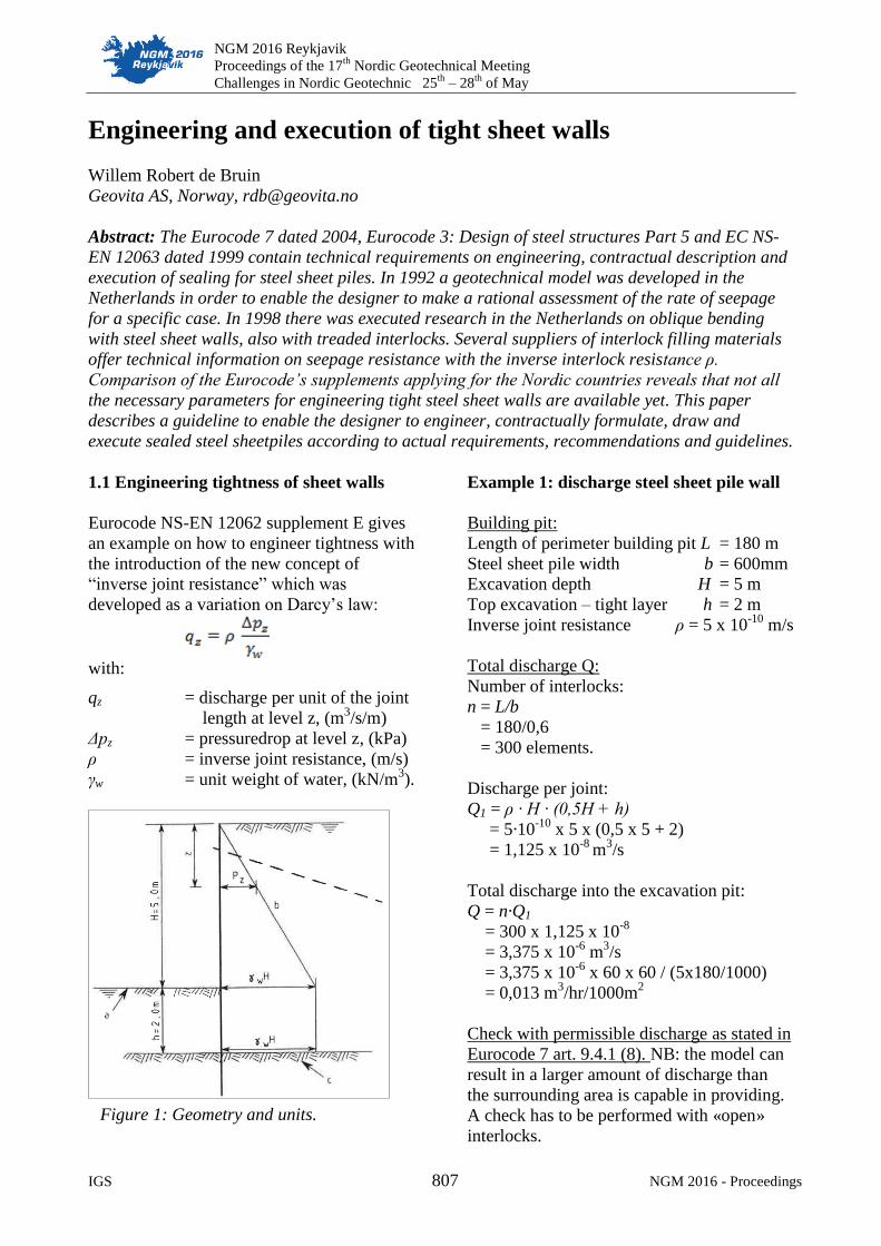
Example 1: discharge steel sheet pile wall
Building pit:
Length of perimeter building pit L = 180 m
Steel sheet pile width b = 600mm
Excavation depth H = 5 m
Top excavation – tight layer h = 2 m
Inverse joint resistance ρ = 5 x 10⁻¹⁰
m/s
Total discharge Q:
Number of interlocks:
n = L/b
= 180/0,6
= 300 elements.
Discharge per joint:
Q1 = ρ · H · (0,5H + h)
= 5·10-10
x 5 x (0,5 x 5 + 2)
= 1,125 x 10-8
m3/s
Total discharge into the excavation pit:
Q = n·Q1
= 300 x 1,125 x 10-8
= 3,375 x 10-6
m3/s
= 3,375 x 10-6
x 60 x 60 / (5x180/1000)
= 0,013 m3/hr/1000m
2
Check with permissible discharge as stated in
Eurocode 7 art. 9.4.1 (8). NB: the model can
result in a larger amount of discharge than
the surrounding area is capable in providing.
A check has to be performed with «open»
interlocks.
Figure 1: Geometry and units.
Geotechnical structures
NGM 2016 - Proceedings 808 IGS
There are no rules to calculate the water
seepage for diaphragm walls in Eurocode
NS-EN 1538 «Execution of special
geotechnical works. Diaphragm walls», and
neither for secant-, cut off- or slurry walls.
Formulas which apply to this field are
according Darcy’s law, se reference /1/:
with:
Qsv = discharge pr unit of wall, (m3/s),
Ke = equivalent permeability (m/s),
Δρ = pressure drop on both side of
the wall, (kPa)
pz = inverse joint resistance, (m/s),
γw = water density, (kN/m3)
d = thickness of the wall, (m)
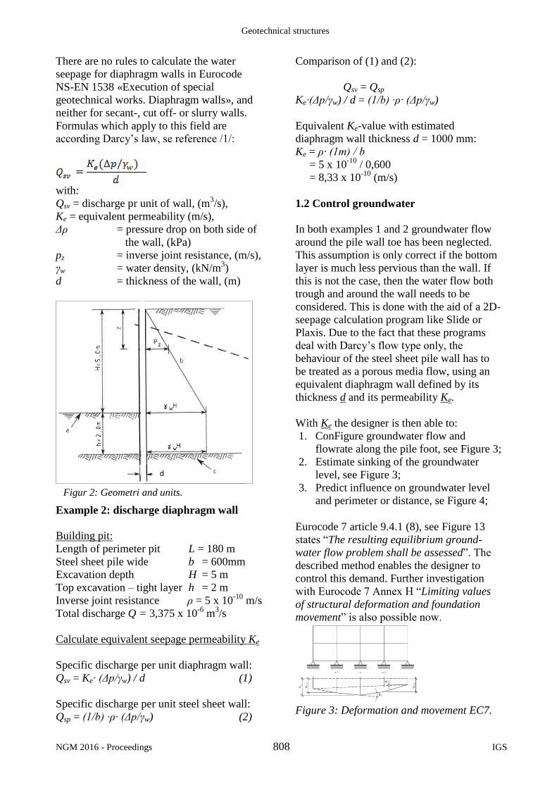
Example 2: discharge diaphragm wall
Building pit:
Length of perimeter pit L = 180 m
Steel sheet pile wide b = 600mm
Excavation depth H = 5 m
Top excavation – tight layer h = 2 m
Inverse joint resistance ρ = 5 x 10⁻¹⁰
m/s
Total discharge Q = 3,375 x 10-6
m3/s
Calculate equivalent seepage permeability Ke
Specific discharge per unit diaphragm wall:
Qsv = Ke· (Δp/γw) / d (1)
Specific discharge per unit steel sheet wall:
Qsp = (1/b) ·ρ· (Δp/γw) (2)
Comparison of (1) and (2):
Qsv = Qsp
Ke·(Δp/γw) / d = (1/b) ·ρ· (Δp/γw)
Equivalent Ke-value with estimated
diaphragm wall thickness d = 1000 mm:
Ke = ρ· (1m) / b
= 5 x 10⁻¹⁰
/ 0,600
= 8,33 x 10⁻¹⁰
(m/s)
1.2 Control groundwater
In both examples 1 and 2 groundwater flow
around the pile wall toe has been neglected.
This assumption is only correct if the bottom
layer is much less pervious than the wall. If
this is not the case, then the water flow both
trough and around the wall needs to be
considered. This is done with the aid of a 2D-
seepage calculation program like Slide or
Plaxis. Due to the fact that these programs
deal with Darcy’s flow type only, the
behaviour of the steel sheet pile wall has to
be treated as a porous media flow, using an
equivalent diaphragm wall defined by its
thickness d and its permeability Ke.
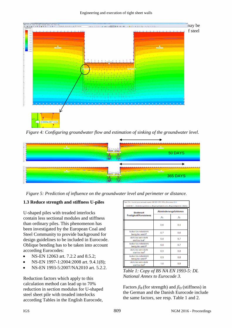
With Ke the designer is then able to:
1. ConFigure groundwater flow and
flowrate along the pile foot, see Figure 3;
2. Estimate sinking of the groundwater
level, see Figure 3;
3. Predict influence on groundwater level
and perimeter or distance, se Figure 4;
Eurocode 7 article 9.4.1 (8), see Figure 13
states “The resulting equilibrium ground-
water flow problem shall be assessed”. The
described method enables the designer to
control this demand. Further investigation
with Eurocode 7 Annex H “Limiting values
of structural deformation and foundation
movement” is also possible now.
Figure 3: Deformation and movement EC7.
Figur 2: Geometri and units.
d
Engineering and execution of tight sheet walls
IGS 809 NGM 2016 - Proceedings
1.3 Reduce strength and stiffness U-piles
U-shaped piles with treaded interlocks
contain less sectional modules and stiffness
than ordinary piles. This phenomenon has
been investigated by the European Coal and
Steel Community to provide background for
design guidelines to be included in Eurocode.
Oblique bending has to be taken into account
according Eurocodes:
NS-EN 12063 art. 7.2.2 and 8.5.2;
NS-EN 1997-1:2004:2008 art. 9.4.1(8);
NS-EN 1993-5:2007/NA2010 art. 5.2.2.
Reduction factors which apply to this
calculation method can lead up to 70%
reduction in section modulus for U-shaped
steel sheet pile with treaded interlocks
according Tables in the English Eurocode,
see Table 3. As a consequence, it may be
necessary to choose another type of steel
sheet pile.
Table 1: Copy of BS NA EN 1993-5: DL
National Annex to Eurocode 3.
Factors βB (for strength) and βD (stiffness) in
the German and the Danish Eurocode include
the same factors, see resp. Table 1 and 2.
Figure 5: Prediction of influence on the groundwater level and perimeter or distance.
50 DAYS
365 DAYS
Figure 4: Configuring groundwater flow and estimation of sinking of the groundwater level.

Geotechnical structures
NGM 2016 - Proceedings 810 IGS
Table 2: Copy of BS NA EN 1993-5: DK NA
to Eurocode 3: Design of steel structures.
Table 3: Copy of BS NA EN 1993-5: UK NA
to Eurocode 3: Design of steel structures.
Other Nordic countries like Sweden, Finland
and Norway do not offer parameters for βB
and βD, see Figure 6 for the Norwegian
Eurocode. This needs further research and
updating.
Figure 6: Copy from NS-EN 19935:2007/NA:
2010. Eurocode 3; Part 5: Piles.
1.4 Reduced overall bending resistance
In the case of differential water pressure
exceeding 5 m head for Z-piles and 20 m for
U-piles the effects of water pressure on
transverse local plate bending should be
taken into account to determine the overall
bending resistance, see Table 4:
NS-EN 1993-5:2007/NA2010 art. 5.2.4
Table 4: BS NA EN 1993-5- Table A-3.
Transverse bending is a relatively newly
recognized mode of failure in sheet piling.
Although it interacts with classical bending,
it is a separate failure mode of its own.
Figure 8: transverse loading on sheet pile.
See Figure 8. In essence, the lateral pressure
is flattening the sheet; the plate bending at
the corners is the resistance of the sheeting to
this flattening.
1.5 Control of driveability
Requirements on driveability are set in
Eurocode:
NS-EN 1997-1:2004-NA:2008, art. 9.4.1
NS-EN 12063 art. 5.2.1, 5.2.2 and 8.5.
These demands need further investigation in
order to reduce the chance of damage and to
avoid sheet piles coming out of their locks.
The change on declutching is less with U-
piles than with Z-shaped steel sheet piles.
Figure 9: Driveability prediction GRL-Weap

Engineering and execution of tight sheet walls
IGS 811 NGM 2016 - Proceedings
1.6 Proportional contribution leakage
Leakage into building pits often occur as a
result of following causes, shown in fig.10:
1) Through the sheet pile wall;
2) Trough and along the anchors;
3) Up along the outside of bored piles;
4) Through cracks and fractures in bedrock.
Figure 10: 4 types of leakages.
Modelling these last 3 types of leakage is
possible by using Darcy’s law, as used for
modelling seepage with steel sheet walls. The
models are represented in Figure 11 to 13.
Figure 11: Leakage along / trough anchors.
Figure 12: Leakage along bored piles.
Groundwater flow along rammed piles can be
calculated using (Darcy’s law based) models
developed for rammed piles through
contaminated landfills, see ref. /8/ and /9/.
Leakage trough bedrock can be modelled
with (Darcy’s law based) models for cracks
as plates or channels see ref. /11/.
Figure 13: Leakage through cracks and
fractures in the bedrock.
Insight into contribution of steel sheet walls
compared to other leakage types is shown in
Table 5. This approach allows the designer to
conFigure the building pit: rammed piles
instead of bored piles, struts instead of
anchors or extra measures as jet piling.
Table 5: Proportional distribution of leakage types.
Geotechnical structures
NGM 2016 - Proceedings 812 IGS
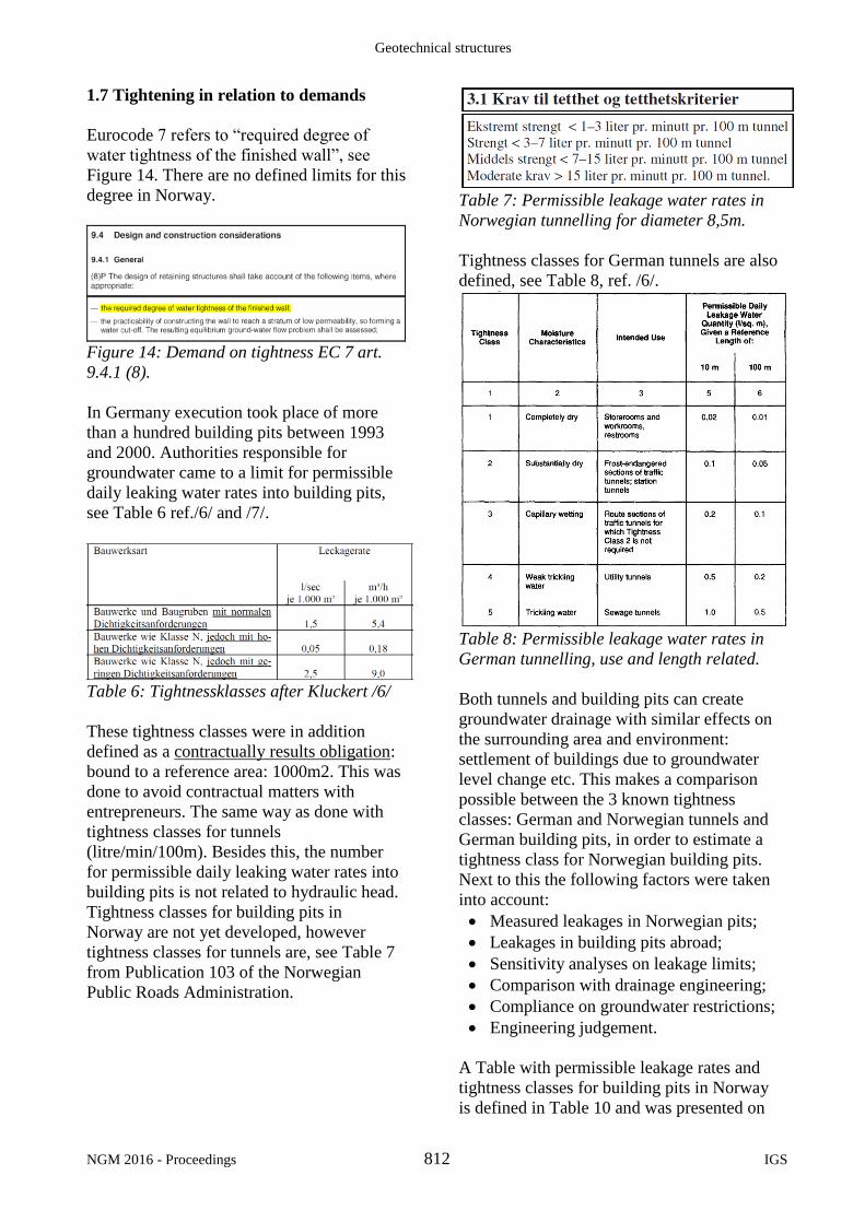
1.7 Tightening in relation to demands
Eurocode 7 refers to “required degree of
water tightness of the finished wall”, see
Figure 14. There are no defined limits for this
degree in Norway.
Figure 14: Demand on tightness EC 7 art.
9.4.1 (8).
In Germany execution took place of more
than a hundred building pits between 1993
and 2000. Authorities responsible for
groundwater came to a limit for permissible
daily leaking water rates into building pits,
see Table 6 ref./6/ and /7/.
Table 6: Tightnessklasses after Kluckert /6/
These tightness classes were in addition
defined as a contractually results obligation:
bound to a reference area: 1000m2. This was
done to avoid contractual matters with
entrepreneurs. The same way as done with
tightness classes for tunnels
(litre/min/100m). Besides this, the number
for permissible daily leaking water rates into
building pits is not related to hydraulic head.
Tightness classes for building pits in
Norway are not yet developed, however
tightness classes for tunnels are, see Table 7
from Publication 103 of the Norwegian
Public Roads Administration.
Table 7: Permissible leakage water rates in
Norwegian tunnelling for diameter 8,5m.
Tightness classes for German tunnels are also
defined, see Table 8, ref. /6/.
Table 8: Permissible leakage water rates in
German tunnelling, use and length related.
Both tunnels and building pits can create
groundwater drainage with similar effects on
the surrounding area and environment:
settlement of buildings due to groundwater
level change etc. This makes a comparison
possible between the 3 known tightness
classes: German and Norwegian tunnels and
German building pits, in order to estimate a
tightness class for Norwegian building pits.
Next to this the following factors were taken
into account:
Measured leakages in Norwegian pits;
Leakages in building pits abroad;
Sensitivity analyses on leakage limits;
Comparison with drainage engineering;
Compliance on groundwater restrictions;
Engineering judgement.
A Table with permissible leakage rates and
tightness classes for building pits in Norway
is defined in Table 10 and was presented on
Engineering and execution of tight sheet walls
IGS 813 NGM 2016 - Proceedings
the “Geoteknikkdag 2015”. With these
proposed requirements the demand in
Eurocode 7 art. 9.4.1 (8), see Figure 14, are
fulfilled and it is now possible for the
designer to combine the models shown in
Figure 11 to 13 with the newly defined limit.
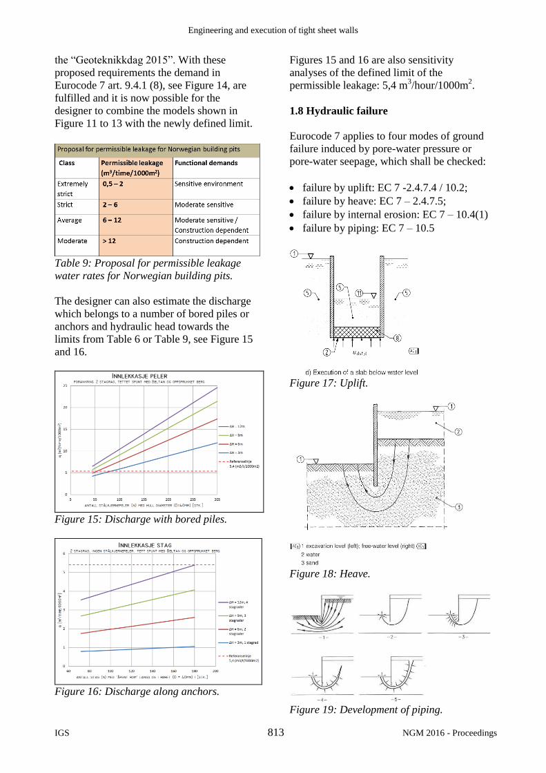
Table 9: Proposal for permissible leakage
water rates for Norwegian building pits.
The designer can also estimate the discharge
which belongs to a number of bored piles or
anchors and hydraulic head towards the
limits from Table 6 or Table 9, see Figure 15
and 16.
Figure 15: Discharge with bored piles.
Figure 16: Discharge along anchors.
Figures 15 and 16 are also sensitivity
analyses of the defined limit of the
permissible leakage: 5,4 m3/hour/1000m
2.
1.8 Hydraulic failure
Eurocode 7 applies to four modes of ground
failure induced by pore-water pressure or
pore-water seepage, which shall be checked:
failure by uplift: EC 7 -2.4.7.4 / 10.2;
failure by heave: EC 7 – 2.4.7.5;
failure by internal erosion: EC 7 – 10.4(1)
failure by piping: EC 7 – 10.5
Figure 17: Uplift.
Figure 18: Heave.
Figure 19: Development of piping.
Geotechnical structures
NGM 2016 - Proceedings 814 IGS
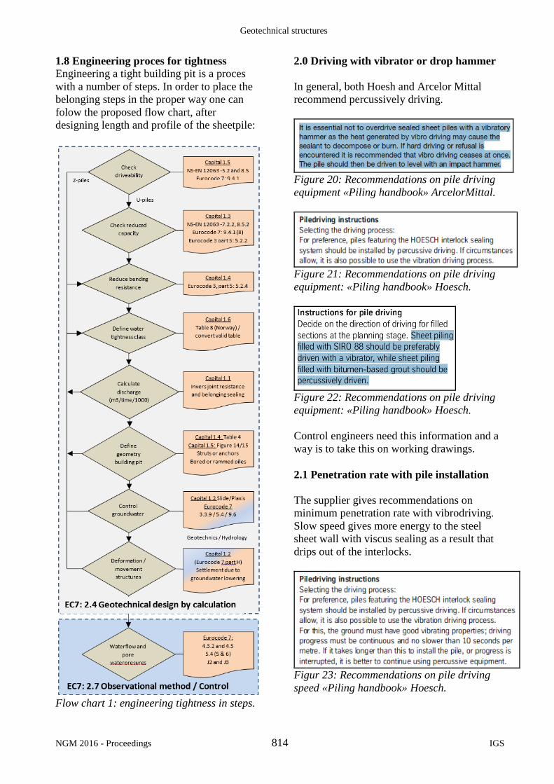
1.8 Engineering proces for tightness
Engineering a tight building pit is a proces
with a number of steps. In order to place the
belonging steps in the proper way one can
folow the proposed flow chart, after
designing length and profile of the sheetpile:
Flow chart 1: engineering tightness in steps.
2.0 Driving with vibrator or drop hammer
In general, both Hoesh and Arcelor Mittal
recommend percussively driving.
Figure 20: Recommendations on pile driving
equipment «Piling handbook» ArcelorMittal.
Figure 21: Recommendations on pile driving
equipment: «Piling handbook» Hoesch.
Figure 22: Recommendations on pile driving
equipment: «Piling handbook» Hoesch.
Control engineers need this information and a
way is to take this on working drawings.
2.1 Penetration rate with pile installation
The supplier gives recommendations on
minimum penetration rate with vibrodriving.
Slow speed gives more energy to the steel
sheet wall with viscus sealing as a result that
drips out of the interlocks.
Figur 23: Recommendations on pile driving
speed «Piling handbook» Hoesch.

Engineering and execution of tight sheet walls
IGS 815 NGM 2016 - Proceedings
2.2 Puling steel sheet piles
With pile driving it is usual and common to
sporadically pull a pile in order to check the
condition of the pile foot or to correct the
angle of the piles. In this case he sealing
should be repaired or the pile should be
replaced by a new pile with sealing. See
Figure 24.
Figure 24: Recommendations on pile driving
equipment «Piling handbook» ArcelorMittal.
Eurocode NS-EN 12063:1999, article 8.11
handles about puling steel sheet piles
2.3 Ramming method
It is important that steel sheet walls with
sealing are installed on a proper way.
Eurocode NS-EN 12063 supplement D gives
guidelines on ramming methods, see Figure
25.
Figur 25: Supplement D Figure D1 from NS-
EN 12063:1999.
Different methods for ramming steel sheet
piles and guidelines are also available with
the supplier: «Panel driving» og «Staggered
driving». See also Figure 29. The proper
method should be described on the working
drawings and in the contract.
2.4 Driving guides
In order to prevent scraping of the sealing
while ramming by piles which are twisted,
see Figure 27, the supplier gives guidelines
on the use of “driving guides”.
Figur 26: Change on scraping of sealing.
Eurocode NS-EN 12063 article 8.5.8 and
8.5.9 also gives instructions and guidelines
on use of driving guides for ramming.
Figur 27: 8.5.8 and 8.5.9 NS-EN 12063:1999
2.5 Driving direction
Driving direction of steel sheet piles is
dependent on type of sealant, type of steel
sheet pile: U- or Z-shaped, single or double
pile and the phenomenon’s «Piles lagging» or
«Piles leading», se Figure 28 and 29.
Figure 28: Directions from ArcelorMittal.
Figur 29: Directions «Piles lagging» / «Piles
leading» from Hoesch Piling handbook.

Geotechnical structures
NGM 2016 - Proceedings 816 IGS
2.6 Declutching detector
Declutching detectors can be used in soils
that are technically difficult for driving, in
order to guarantee a perfect hooking between
interlocks. Requirements on monitoring sheet
pile driving are given in Eurocode NS-EN
12063 article 9.3.8, see Figure 30. There are
several suppliers of different systems for
declutching detectors.
Figur 30: pkt.9.3.8 NS-EN 12063:1999
2.7 Working drawing
In Norway steel sheet piles are equipped with
steel pipes in order to be able to bore trough
these pipes after installation of the piles. This
boring is done to install a bolt and therefore
secure the foot of the pile. This occurs on the
“dry side”. However, as Figure 31 shows, the
steel sheet pile supplier connects at the
factory first the two single piles into one
double pile, before the sealing is applied.
Figure 31: Sealing (Arcoseal) project
Bjørvikatunnel – Havnelageret.
This implies that the sealing also is placed at
the so called ”dry side” of the pile, given
water the possibility to push the sealing out.
Sealing should always be on the ”wet side”
of the wall. Figure 32 shows proper details on
a working drawing.
Figur 32: Details on working drawing.
Conclusion
For the moment there are no tightness classes
for building pits in Norway. The suggested
method in the different chapters and
proposed Table 9 is meant as a tool towards
the designer and engineer to come to a tight
building pit or retaining wall.
References 1. Arcelor Mittal (2008): “Piling Handbook 8th
edition”;
2. ThyssenKrupp GfT Bautechnik (2010): “Sheet
Piling Handbook 3rd edition”;
3. NS-EN 12063: 1999 Utførelse av spesielle
geotekniske arbeider.
4. NS-EN 1993-5:2007+ NA:2010 Eurokode 3:
Prosjektering av stålkonstruksjoner. Del 5: Peler
(spunt)
5. dr.ir. D.A.Kort (oktober 2004): “On the use of Z
and U piles”, presentation NGF;
6. Kluckert, K.D (Graz 2007).: “Wie dicht ist
dicht?, Christian Veder Kollquium;
7. Borchert, K.-M. (1999): “Dichtigkeit von
Baugruben bei unterschiedlichen Sohlen-
Konstruktionen – Lerhen aus Schadensfällen”
8. T. Katsumi, T.Iniu og M. Kamon (september 8-
10, 2009): «In-situ containment for waste landfill
and contaminated sites», ISGE 2009;
9. Dr. Gordon P. (Piledriver fall 2004): “Pile
foundations – an environmental problem?”;
10. Vegdirektoratet Teknologiavdelingen
Publikasjon 103 (Oslo, januar 2004):
“Berginjeksjon I praksis”.
11. Ing. W.R. de Bruin “Prosjektering og utførelse av
tett spunt”, Geoteknikkdag 2015.