engineering change notice - technical university of …kyb.fei.tuke.sk/psvr/literatura/usb2.pdf ·...
TRANSCRIPT

USB Engineering Change Notice
USB 2.0 ECN: Link Power Management (LPM) 1
ENGINEERING CHANGE NOTICE
Title: USB 2.0 Link Power Management Addendum
Applies to: Universal Serial Bus Specification, Revision 2.0
Summary of ECN This ECN defines a power management feature for USB called Link Power Management (LPM) which is similar to the existing suspend/resume, but has transitional latencies of tens of microseconds between power states (instead of three to greater than 20 millisecond latencies of the USB 2.0 suspend/resume).
It has several parts: (a) it introduces formal terminology for line (bus) states in terms of power states, (b) defines a new, fast mechanism for transitioning the bus on a root port from an enabled state (called L0, see below) to a new Sleep state (called L1, see below), (c) defines new, fast timing requirements for resuming a bus from L1 back to (L0), and (d) defines the method for extending the existing USB protocol to accommodate explicit L1 entry. The L0 (enabled) to L1 (link Sleep) transition is actively initiated by the host using a new USB-defined transaction. This allows a device to immediately detect the intent of the host and respond immediately, instead of the USB 2.0 defined method of ‘discovery by loss of activity’, which requires 3 orders of magnitude more elapsed time. The L1 to L0 transition is similar to the USB 2.0 resume, as it can be initiated by either the host port or the device (i.e. remote wake). However, the duration of resume signaling is redefined to be three orders of magnitude faster (i.e. tens of microseconds, not tens of milliseconds).
The LPM feature may be utilized at any depth in a valid USB connection hierarchy. However, it is expected that the most value to be obtained will be when it is used with root-ports and possibly a single level of hub beyond the root-ports. This is motivated primarily by the fact that the goal is to minimize the transitional latencies. Supporting multiple layers in the hierarchy requires driving devices across the hierarchy of hubs in and out of an L1, in a consistent and coherent fashion takes additional time, which increases latencies to unacceptable durations.
This is an addendum to the USB 2.0 specification. Note there are elements in this ECN that override parts of the USB 2.0 specification. These are called out explicitly where appropriate.
Reasons for ECN USB 2.0 defined standard mechanisms for device power management, based on a simple protocol for detecting suspend and special signaling protocol for allowing either a host or device to initiate resume. USB is an increasingly popular standard bus to connect peripherals both outside and inside the box. The currently supported USB device power management mechanisms, although simple are large grain controls and not intended to be used for micro-managing or optimizing device power. For example, in order to ‘suspend’ a device, a host will suspend traffic on the port the device is connected. The device ‘discovers’ the suspend condition after 3 milliseconds of idle. The device is required to obey a minimum suspend residency of 2 milliseconds (i.e. can initiate a resume only after 2 additional milliseconds after detecting suspend). The resume timing is even more onerous in terms of latency required to bring the link back from suspend. The resume mechanism is engineered to accommodate driving resume events through 5 levels of hierarchy and backward compatibility with devices built to the resume mechanism defined in an older revision of the USB specification.
Existing utilizations of USB suspend/resume are almost exclusively associated only with system state transitions (S3, S4, etc.), which don’t, occur very often and don’t require fast transition times; They attempt to be fast in human perception terms, but not in machine terms. The bus-imposed resume latencies are so long that the mechanism doesn’t support response times that are useful in many applications, especially in hand-held platforms.
The existing suspend/resume mechanisms have been proven by platform architects and product groups to be inadequate for current and future generation mobile platforms. In order to keep USB a relevant

USB Engineering Change Notice
USB 2.0 ECN: Link Power Management (LPM) 2
technology for mobile platforms, it is necessary to update and add features to USB. Note that careful consideration has been taken in deriving the appropriate transitional latencies, where appropriate means reasonable complexity and cost for device implementations.
Impact on Existing Peripherals and Systems The LPM enhancement requires changes to both host and device platforms to take advantage of the feature. As defined below, LPM simply adds a new feature and bus state that co-exists with the USB2.0 defined suspend/resume. As such, it is backward compatible in that a host will be able to determine whether a device supports LPM and a device that supports LPM will continue to work properly with older hosts. The only time LPM is used is when a device properly acknowledges a sleep transaction (described below). Similarly, the new resume timings are not used unless the link is transitioned to the L1 state via the sleep transaction.
Hardware Implications There are no changes to the physical (analog) layer. The line state for L1 (Sleep) and USB 2.0 Suspend are identical (that is Full or Low-speed idle). There are no changes to resume signaling levels, end-of-resume signaling event (connect-speed dependent EOP), and subsequent line states.
The device and host will require a new (link power state-specific) resume state machine (which may be able to use/share portions of the existing resume state machines) in order to accommodate the shorter event times. Depending on current implementations, a faster or different clock than is currently in use to detect the start of resume signaling may be needed; still this clock can be relatively slow as compared to the native clock used to drive signaling.
A device must be able to decode a new extension transaction. The extension transaction uses an undefined PID which by the USB 2.0 definition must result in no response by addressed devices and ignored by other devices. The footprint of the new extension transaction borrows the method and form of split transactions. Since this can be applied to FS/LS devices, the expectation is that the new transaction format (see below) won’t disturb existing device implementations.
A host or hub must generate the new transaction when appropriate.
Software Implications The mechanisms defined here are the ‘bus-level’ mechanisms required for the host port and device to properly operate. A host controller may allow host software to enable/disable this feature, or may provide other mechanisms to allow software to manage the feature. However, these decisions are up to host controller implementers and beyond the scope of this ECN. The host will need to (at least) expose a control for compliance testing in order to allow testing of the L1 and new resume timings.
Compliance Testing Implications Compliance to this feature is quite easy to test. The L1 is an explicit transaction, which is easily captured via a bus analyzer. In addition, the resume signaling is easily captured and measured using mostly existing test procedures (modified only to accommodate the new timings).
Specification Addendum The following is the text for the addendum to the USB 2.0 specification.

USB Engineering Change Notice
USB 2.0 ECN: Link Power Management (LPM) 3
1. Link Power Management (LPM) This addendum for USB defines power management states (LPM states) and mechanisms to affect state changes
that are used by hosts and hubs to efficiently manage bus and system power. The ‘Link’ in this context is
intended to encapsulate the downstream facing port of a host or hub, the upstream facing port of a device and
the data lines connecting the ports. The LPM states are defined in detail in Table 1-1. Note that the L0, L2 and
L3 states are formal names for conditions already defined, but unnamed in the USB 2.0 specification. There are
no changes suggested or implied to device, hub or device behavior under L0, L2 or L3 states. Section 1.1 details
the requirements of hosts/hub and devices related to the L1 state.
Port commands are used to manage the transition of a link from L0 and L1 (see Section 4), regardless of whether
the link to be transitioned is a root port or a downstream port of a discrete hub. This is similar to how all other
link-specific states are managed in USB 2.0. The role and responsibilities are the same for either the hub or host
that owns the port to which the port command is addressed. Therefore, in this addendum, with respect to LPM
activities, the host and hub are referred to interchangeably.
Table 1-1. USB Link Power Management (Lx) States
LPM State Description
L0 (On) In this state, the port is enabled for propagation of transaction signaling traffic. A port in L0 is either actively transmitting or receiving data (L0-Active) or able to do so but not currently transmitting or receiving information (L0-Idle). While in this state Start-of-Frame (SOF) packets are issued by the host at a rate corresponding to the speed of the client device
(1ms for full-speed, 125s for high-speed). Note, the host transmits keep alives or the USB 2.0 hub translates some SOFs into keep alives if the device connected on the downstream port is a Low-speed device. The line state during L0-Active and L0-Idle vary according link speed as does the mechanism by which the host detects device hot-removal (e.g. during SOF phase for high-speed devices). Entry to L0 is via reset or resume signaling (either from L1 or L2).
L1 (Sleep) L1 is similar to L2 (below) but supports finer granularity in use. When in L1, the line state is identical to L2 (see below). Entry to L1 is started by a request to a hub or host port to transition to L1. A LPM transaction is sent to the downstream device. The requested transition can only occur if the device response with an ACK handshake (see Section 2.2)). Exit from L1 is via remote wake, resume signaling, reset signaling or disconnect.
L1 does not impose any specific power draw requirements (from VBUS) on the attached device as L2 does. Either the host or device can initiate resume signaling when in L1. Although the signaling levels of resume are the same as L2, the duration of the signaling and transitional latencies associated with the L1 to L0 transition are much shorter (see Section 1.1).
L2 (Suspend) This is the formalized name for USB 2.0 Suspend, see Section 7.1.7.6 in the USB 2.0 specification. Entry to L2 is nominally triggered by a command to a hub or host port to transition to suspend, at which point the port ceases repeating signaling down the port (and may transition the port out of high-speed mode). The device discovers the suspend condition via observing 3ms of inactivity. The resultant line state is either Low or Full-speed idle (see Section 7.1.7.6).
L2 also imposes power draw requirements (from VBUS) on the attached device (see Section 7.1.7.6). Exit from this state is via remote wake, resume signaling, reset signaling or disconnect.
L3 (Off) In this state, the port is not capable of performing any data signaling. It corresponds to the powered-off, disconnected, and disabled states.
Figure 1-1 illustrates the allowed LPM state transitions. For example, a host must transition a link from L1
(Sleep) to L0 before transitioning it to L2 (Suspend), and similarly when transitioning from L2 to L1.

USB Engineering Change Notice
USB 2.0 ECN: Link Power Management (LPM) 4
L0
Reset and Enable
L3
L1 L2
3ms of inactivity
Resume / Remote Wake
Signaling levels: USB
2.0 defined for resume
Timing: USB 2.0
defined for resume
Remote Wake
enabled by
SetFeature(Device, RemoteWake)
ACK response to LPM
Resume / Remote Wake
Signaling levels : same
as L2 to L0
Timing is L1 specific
Disconnect, Power
loss, and Disable
Remote Wake
enabled by
LPM Transaction
Figure 1-1. LPM State Transition Diagram
1.1 LPM State: L1 (Sleep) The L1 (Sleep) LPM state differs from the L2 (USB 2.0 Suspend) state in two ways: the transitional latencies
into and out of the state are much shorter (than L2) and there are no explicit power draw requirements on the
attached device (L2 requires a suspended device to reduce its power draw from VBUS). Although there are no
specification-mandated power requirements, the device won’t be monitoring bus activity when its upstream port
is in L1 and should take the opportunity to conserve power whenever possible. The host will provide an
indication to the device on the minimum time it will be driving resume if it (the host) initiates L1 exit. The
indicator is set by the host based on its current workload policies and will be in the range 50 to 1200 µs. The
device can use the value of this indicator to deploy its own power efficiency optimizations, based on the
responsiveness indicated by the host.
L1 supplements the existing L2 state by utilizing most of the existing suspend/resume infrastructure (signaling
levels, line states while in the state, etc.) but, provides much faster transitional latencies between L1 and L0
(On).
Note a host must not initiate an action that results in the transmittal of an LPM transaction to a device unless it
(the addressed device) is connected directly to a port downstream of the host or hub. The host must not initiate a
command to issue an LPM transaction to a host or hub port when a split transaction is in flight to the addressed
device.
Table 1-2 includes comparisons between the L1 and L2 LPM states.
Table 1-2. Summary Similarities/Differences Between L1 and L2
L1 (Sleep) L2 (Suspend)
Entry Explicitly entered via LPM extended transaction
Implicitly entered via 3ms of link inactivity
Exit Device or host-initiated via resume signaling; Remote-wake can be (optionally) enabled/disabled via the LPM transaction.
Device- or host-initiated via resume signaling; device-initiated resumes can be (optionally) enabled/disabled by software
Signaling Low and Full- speed idle Low and Full-speed idle
Latencies Entry: ~10s
Exit: ~70s to 1ms (host-specific)
Entry: ~3ms Exit: >30ms (OS-dependent)
Link Power
Consumption
~0.6mW (data line- pull-ups) ~0.6mW (data line- pull-ups)

USB Engineering Change Notice
USB 2.0 ECN: Link Power Management (LPM) 5
Table 1-2. Summary Similarities/Differences Between L1 and L2 (cont.)
L1 (Sleep) L2 (Suspend)
Device Power
Consumption
Device power consumption level is application/implementation specific
Device consumption is limited to: 500 µA or
2.5mA
Hot Removal Natively detected per USB2 mechanisms Natively detected per USB 2.0 mechanisms
Note, the time from the link returning to L0 (from L1) and the first transaction addressed to the device is host controller
implementation specific. It is recommended that hosts service endpoints on the device as quickly as possible (given current
host controller state transfer type of endpoints on the device and service interval). For example, quickly servicing reduces or
avoids unnecessary latency in the data stream and may also provide an early opportunity to transition the link back to L1.
2. Protocol A transaction is used to request a device connected to a port to transition to L1. USB 2.0 had only one ‘reserved’
PID value, so an extension transaction is defined to allow future protocol extensibility. This section is organized
into two parts: Section 2.1 defines the extension (EXT) transaction framework and Section 2.2 defines the LPM
extended transaction.
2.1 USB 2.0 Extension Transaction The extension transaction uses the remaining USB 2.0 reserved PID value (0000B), which is in the Special PID
type group. This addendum names this PID value the EXT PID, as illustrated in Table 2-1. Note, this table
overrides Table 8-1 PID Types in the USB specification, Revision 2.0.
Table 2-1 PID Types
PID Type PID Name PID<3:0>* Description
Token OUT
IN
SOF
SETUP
0001B
1001B
0101B
1101B
Address + endpoint number in host-to-function transaction Address + endpoint number in function-to-host transaction
Start-of-Frame marker and frame number
Address + endpoint number in host-to-function transaction for SETUP to a control pipe
Data DATA0
DATA1
DATA2
MDATA
0011B
1011B
0111B
1111B
Data packet PID even
Data packet PID odd
Data packet PID high-speed, high bandwidth isochronous transaction in a microframe (see Section 5.9.2 for more information)
Data packet PID high-speed for split and high bandwidth isochronous transactions (see Sections 5.9.2, 11.20, and 11.21 for more information)

USB Engineering Change Notice
USB 2.0 ECN: Link Power Management (LPM) 6
Table 2-1 PID Types (cont.)
PID Type PID Name PID<3:0>* Description
Handshake ACK
NAK
STALL NYET
0010B
1010B
1110B
0110B
Receiver accepts error-free data packet
Receiving device cannot accept data or transmitting device cannot send data
Endpoint is halted or a control pipe request is not supported No response yet from receiver (see Sections 8.5.1 and 11.17-11.21)
Special PRE ERR SPLIT PING
EXT
1100B
1100B
1000B
0100B
0000B
(Token) Host-issued preamble. Enables downstream bus traffic to low-speed devices. (Handshake) Split Transaction Error Handshake (reuses PRE value) (Token) High-speed Split Transaction Token (see Section 8.4.2) (Token) High-speed flow control probe for a bulk/control endpoint (see Section 8.5.1)
(Token) Protocol extension token (see Section 2.1.1)
*Note: PID bits are shown in MSb order. When sent on the USB, the rightmost bit (bit 0) will be sent first.
2.1.1 Protocol Extension Token
This addendum defines an extended token phase used to extend the USB transaction protocol. The token phase
for an EXTended transaction is comprised of two token packets (each a standard 3 byte token packet), see
Figure 2-1.
PID
(8)
ADDR ENDP CRC5
(7) (4) (5)
SubPID variable CRC5
(11) (5)(8)
PID = 0000B {EXT PID}Contents depends on value of SubPID field
Token Phase
Data Handshake
Token Packet
Extended
Token Packet
Transaction
depends on value
of SubPID field
Figure 2-1. Packets in an Extension Token Transaction
The first packet of an extension transaction is a standard token packet with EXT in the PID field, including:
ADDR, ENDP and CRC5 fields. The EXT PID indicates that the next packet (with standard, back-to-back inter-
packet timing) is an extended token packet.
The second packet of an extension transaction is the Extended Token packet. The basic structure of this packet
is identical to a standard token packet in that the first field is a PID (subPID) field and the end of the packet
contains a CRC5, which is used to check the 11 bits between the SubPID field and the CRC5. The format of the

USB Engineering Change Notice
USB 2.0 ECN: Link Power Management (LPM) 7
variable field in the extension token packet depends on the value of the SubPID field. Table 2-2 lists the defined
SubPID codes. As with existing token packets, the SubPID value indicates the direction and format of the
remainder of the transaction. This allows definition of transactions with data phases with in-bound or out-bound
data, and inclusion or omission of a handshake phase. Note that an extended transaction has an effective 6 bytes
of token information.
Table 2-2. SubPID Types
SubPID Name PID<3:0> Description
N/A 0000B Reserved for future use
Reserved 0001B 1001B 0101B 1101B 1000B 0100B 1100B
These PID values must not be used for Extended Token packet PIDs. These values are used for the Tokens in the base PID table (see Table 2-1 PID Types, above) and cannot be reused for SubPID types.
LPM 0011B LPM token
1011B 0111B 1111B 0010B 1010B 1110B 0110B
Reserved for future use
2.2 USB 2.0 LPM Extended Transaction This section defines the format of the LPM extended transaction. The first sub-section 2.2.1 defines the LPM
token and sub-section 2.2.2 defines the semantics of the LPM transaction.
2.2.1 LPM Token
The LPM token packet is only valid in an Extended transaction format, as illustrated in Figure 2-2.
Token Packet Inter-packet Gap
Extended Token Packet
(lsb) (msb) (lsb) (msb)
Field
EXT
PID
ADDR ENDP CRC5 LPM
SubPID bmAttributes CRC5
Bits 8 7 4 5 8 11 5
Figure 2-2. LPM Extended Token
The format of the bmAttributes field of the LPM token is illustrated in Table 2-3.

USB Engineering Change Notice
USB 2.0 ECN: Link Power Management (LPM) 8
Table 2-3. LPM Token bmAttributes Field Definition
Bits Field Description
10:9 Reserved Reserved for future use
8 bRemoteWake A value of one (1B) in this field enables the addressed device to wake the host upon any meaningful application-specific event (e.g. an interrupt for a device with one or more interrupt endpoints).
A value of zero (0B) disables the device from initiating remote wake.
7:4 HIRD Host Initiated Resume Duration. See Section 4.1 for value defintion.
3:0 bLinkState The link state (Lx) the addressed device must transition to after responding to this transaction with an ACK. Valid values for this field are:
Value Description
0000B Reserved for future use
0001B L1 (Sleep)
0010B – 1111B
Reserved for future use
Refer to Section 2.2.2 for a full definition for the LPM transaction and Section 1 for a full overview of Link
Power Management.
2.2.2 LPM Transaction
LPM transactions are used by a host to transition a host to device link to a specific link power management state
(see Section 1). An LPM transaction is a two phase extended USB transaction, consisting of an extended token
phase (two token packets) and a handshake phase (handshake packet) as shown in Figure 2-3. Note that the EXT
token must be transmitted before the LPM token.
EXT
idle
LPMToken
ACKHandshake NYET
idle
Error
Host Function
STALL
Figure 2-3. LPM Transaction Format
When a host is ready to transition a port from L0 to a deeper power savings state, it issues a command to the
port, which results in an LPM transaction. The device function responds with an ACK if it is ready to make the
transition or a NYET if it is not currently ready to make the transition usually because it has data pending for the
host. A device must transmit a STALL handshake if it does not support the requested link state (Lx, see the
bmAttributes field of the extended LPM transaction). If the device detects errors in either of the token packets or
does not understand the protocol extension transaction, no handshake is returned.

USB Engineering Change Notice
USB 2.0 ECN: Link Power Management (LPM) 9
3. Framework: USB Device Capabilities – USB 2.0 Extension This section defines an optional device-level, capabilities descriptor for wired USB devices, and provides an
indicator in the existing USB 2.0 framework that system software can use to determine that the device supports
the new reporting descriptor type.
A unique descriptor is used to report additional USB 2.0 device-level capabilities that are not reported via the
Device descriptor. The USB Device Capabilities – USB 2.0 Extension descriptor is only available with a BOS
descriptor set. The BOS descriptor is defined in Section 7.4.1 of the Certified Wireless USB Specification,
Revision 1.0. This descriptor cannot be accessed directly by a GetDescriptor() or SetDescriptor() request.
Table 3-1. USB Device Capabilities – USB 2.0 Extension Descriptor
Offset Field Size Value Description
0 bLength 1 Number Size of this descriptor.
1 bDescriptorType 1 Constant Descriptor type: DEVICE CAPABILITY Type.
2 bDevCapabilityType 1 Constant Capability type: USB 2.0 EXTENSION (002H)
3 bmAttributes 4 Bitmap Bitmap encoding of supported device level features. A value of one in a bit location indicates a feature is supported; a value of zero indicates it is not supported. Encodings are:
Bit Encoding
0 Reserved. Must be set to zero.
1 LPM. A value of one in this bit location indicates that this device supports the Link Power Management protocol.
31:2 Reserved. Must be set to zero.
The value of the bcdUSB field in the standard USB 2.0 Device Descriptor is used to indicate that the device
supports the request to read the BOS Descriptor (i.e. GetDescriptor(BOS)). Devices that support the BOS
descriptor must have a bcdUSB value of 0201H or larger.
4. Hub This section is a supplement to the Hub device definition chapter in the USB 2.0 specification. Some portions of
this section over-ride or supplement information in the USB 2.0 specification. These are called out where
applicable.
The mechanisms in USB 2.0 to manage port states are via Get/Clear/Set Port Feature commands. Most hosts
provide equivalent controls to system software for the downstream ports. LPM adds extensions to the port
management command set for managing the L1 link state. It is recommended that hosts provide equivalent
mechanisms to those defined below.
Managing the L1 state of a port is intended to be very similar to managing a port’s L2 (Suspend) state,
including: a request to transition into the state, a request to explicitly transition the port out of the state, a request
to inquire about the current state and support for remote wake. This addendum defines extensions to the USB
2.0 Hub port feature management commands and also defines a new management command for transitioning a
port into the L1 state. The resume timing requirements (L1 to L0) apply equally to both hubs and hosts unless
explicitly noted otherwise.

USB Engineering Change Notice
USB 2.0 ECN: Link Power Management (LPM) 10
4.1 L1 Entry – Hub Operational Model The operational control model for placing a port into L1 is similar to placing a port into L2 (Suspend), i.e. a
command is sent via the Default Control Pipe to the hub, requesting it to transition a specific port to L1. A new
SET and TEST control read transfer is used for this command. The operational command is fully contained in
the SETUP stage and the DATA stage is used to return a completion code for the command. On receipt of the
SETUP stage of the request to transition a port to L1, the hub begins NAKing the data stage transaction and
quickly services the command. When the command is complete, it returns a completion code in the DATA stage
and the host will complete the transfer with the STATUS stage. The details of this command are provided in
Section 4.10.1. The port control model is illustrated in Figure 4-1.
Host
SetandTestPortFeature ()
Hub
LPM Transaction ()
Device
Params:
Device Address,
Link State = L1,
Remote Wake Flag,
HIRD parameter
Handshake value
Hub idles port and issues
LPM transaction
LPM Completion Code
Parameters in SETUP Data:
LPM Transition Request,
Hub Address,
Port Number (downstream),
Device Address,
Link State (L1),
Remote Wake Flag,
HIRD parameter
Setup
Data (IN)
INNAK
IN
Status OUTACK
Figure 4-1. Port Control Model for Transitioning a Port to L1
If the designated port is in the proper state (i.e. enabled) when the request to transition to L1 is received, the hub
first stops repeating traffic down the port by the next micro-frame boundary (after the SETUP stage was
received) and issues an LPM transaction to the device (independent of the traffic which may be occurring on the
other ports). When the LPM transaction completes the hub evaluates the results of the transaction to determine
what to do with the port and what completion code to return to the host. If the device responds with an ACK, the
port is placed into the L1 state and a SUCCESS completion code is sent back to the host. If the device responds
with a NYET, the port is returned to the enabled state (restore normal operation) and a completion code of
NYET is sent back to the host. If the hub gets a transaction error (including timeout), it must retry the LPM
transaction two more times. If there are three consecutive errors then the port is returned to the enabled state and
an error completion code (see Section 4.10.3) is sent back to the host.
The hub must respond to the data stage of this control transfer within 200 µs. This allows for an arrival of the
SETUP at the beginning of one micro-frame and for completion of a low-speed transaction in the following
micro-frame, with some additional margin.
The host system sets the Remote Wake Flag parameter in this request to enable or disable the addressed device
for remote wake from L1. The value of this flag will temporarily (while in L1) override the current setting of the
Remote Wake feature settable by the standard Set/ClearFeature() commands defined in Universal Serial Bus
Specification, revision 2.0, Chapter 9.
The host system communicates to the device the duration of how long the host will drive resume when it (the
host) initiates exit from L1 via the HIRD (Host Initiated Resume Duration) parameter. It sets the HIRD value
based on its requirements for responsiveness. For example, it will use short HIRD encodings if it requires low
latency to return the device to full operational state. It will use longer HIRD encodings if the latency to full
operational state are less stringent. The device can use the HIRD value to help determine what power
USB Engineering Change Notice
USB 2.0 ECN: Link Power Management (LPM) 11
optimization features it should employ in response. For example, the device could use long HIRD encodings as a
flag to idle significantly more logic (clocks, logic, etc.) than it would with short HIRD encodings. The power
optimizations and commensurate power reduction in power consumption are device implementation specific.
The HIRD value is a 4-bit encoded value. The value of 0000B is interpreted as 50 µs. Each value up adds 75 µs
to the previous value. For example, 0001B is 125 µs, 0010B is 200 µs and so on. Based on this rule, the
maximum value resume drive time is at encoding value 1111B which represents 1.2ms.
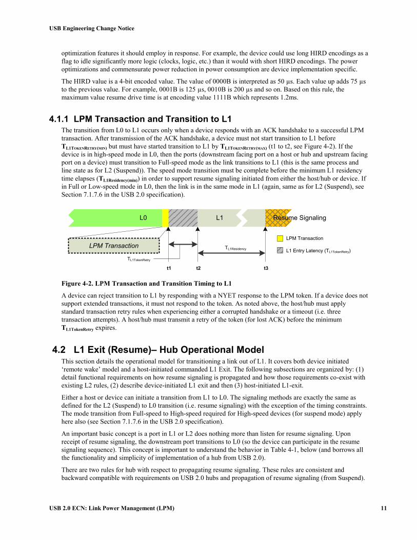
4.1.1 LPM Transaction and Transition to L1
The transition from L0 to L1 occurs only when a device responds with an ACK handshake to a successful LPM
transaction. After transmission of the ACK handshake, a device must not start transition to L1 before
TL1TOKENRETRY(MIN) but must have started transition to L1 by TL1TOKENRETRY(MAX) (t1 to t2, see Figure 4-2). If the
device is in high-speed mode in L0, then the ports (downstream facing port on a host or hub and upstream facing
port on a device) must transition to Full-speed mode as the link transitions to L1 (this is the same process and
line state as for L2 (Suspend)). The speed mode transition must be complete before the minimum L1 residency
time elapses (TL1Residency(min)) in order to support resume signaling initiated from either the host/hub or device. If
in Full or Low-speed mode in L0, then the link is in the same mode in L1 (again, same as for L2 (Suspend), see
Section 7.1.7.6 in the USB 2.0 specification).
LPM Transaction
L0 L1
t1 t2 t3
TL1Residency
LPM Transaction
L1 Entry Latency (TL1TokenRetry)
Resume Signaling
TL1TokenRetry
Figure 4-2. LPM Transaction and Transition Timing to L1
A device can reject transition to L1 by responding with a NYET response to the LPM token. If a device does not
support extended transactions, it must not respond to the token. As noted above, the host/hub must apply
standard transaction retry rules when experiencing either a corrupted handshake or a timeout (i.e. three
transaction attempts). A host/hub must transmit a retry of the token (for lost ACK) before the minimum
TL1TokenRetry expires.
4.2 L1 Exit (Resume)– Hub Operational Model This section details the operational model for transitioning a link out of L1. It covers both device initiated
‘remote wake’ model and a host-initiated commanded L1 Exit. The following subsections are organized by: (1)
detail functional requirements on how resume signaling is propagated and how those requirements co-exist with
existing L2 rules, (2) describe device-initiated L1 exit and then (3) host-initiated L1-exit.
Either a host or device can initiate a transition from L1 to L0. The signaling methods are exactly the same as
defined for the L2 (Suspend) to L0 transition (i.e. resume signaling) with the exception of the timing constraints.
The mode transition from Full-speed to High-speed required for High-speed devices (for suspend mode) apply
here also (see Section 7.1.7.6 in the USB 2.0 specification).
An important basic concept is a port in L1 or L2 does nothing more than listen for resume signaling. Upon
receipt of resume signaling, the downstream port transitions to L0 (so the device can participate in the resume
signaling sequence). This concept is important to understand the behavior in Table 4-1, below (and borrows all
the functionality and simplicity of implementation of a hub from USB 2.0).
There are two rules for hub with respect to propagating resume signaling. These rules are consistent and
backward compatible with requirements on USB 2.0 hubs and propagation of resume signaling (from Suspend).

USB Engineering Change Notice
USB 2.0 ECN: Link Power Management (LPM) 12
Rule1: A hub propagates an L1 exit resume upstream when the upstream port is in L1 or L2. Note, when the
upstream port is in L2, the hub turns the device initiated L1 exit into a normal L2 exit (obeying all of its rules).
This effectively causes the hub to transition its upstream facing port to L0.
Rule2: When a hub whose upstream facing port is in L1 or L2 begins to transmit resume signaling, it will
‘broadcast’ that signaling out all enabled (L0) ports (from Rule1 above, this includes the upstream facing port).
The ‘link’ does not return to L0 until the upstream facing port of the device matches the state of the downstream
facing port. This does not occur ‘officially’ until the end of resume (EOR) is received by the device. This rule
meets the intent of the USB 2.0 specification. Note that this addendum introduces new combinations of upstream
and downstream port power states where some combinations may not result in predictable behavior. In order to
simplify the hub implementation (by not forcing it to track combinations of upstream and downstream port
states), system software is expected to implement the policy described in Section 4.2.1.
4.2.1 Device Initiated L1 Exit
The timing events related to a device initiated L1 exit are illustrated in Figure 4-3. After placing a link into L1, a
host or hub may decide to idle other logic associated with the port, including shutting down high-speed clocks,
etc. The host or hub must be capable of detecting and responding to resume signaling with the timings specified
here, by whatever mechanisms that are appropriate. Figure 4-3 shows two device initiated resume scenarios
which demonstrate the host/hub requirements with respect to detecting and responding to resume signaling,
depending on whether its signaling clock is running at the time the remote wake signaling is detected.
L1
t1
t2 t3
TL1DevDrvResume
Host/Hub drives resume
Resume recovery
L0
TL1ExitLatency2
t4
t5
Device drives resume
(a) Fast Resume Response (~70µs)
L0
t1
t2 t3
TL1ExitLatency2
t4
t5
(b) Slow Resume Response (≤1ms)
L1 Remote Wake
Detect Clock
Signaling Clock
TL1ExitDevRecovery
L1
TL1DevDrvResume
TL1HubDrvResume2TL1HubDrvResume2
TL1ExitDevRecovery
TL1HubReflect(Max)TL1HubReflect(Min)
Figure 4-3. Device Initiated L1 to L0 Transition (Remote Wake)
Figure 4-3 illustrates a device initiated resume (also called Remote Wake). A device initiating L1 exit must
drive resume signaling for nominally TL1DevDrvResume [t1t3]. The host must detect the resume signaling and
reflect it (i.e. drive resume signaling on its corresponding port) within TL1HubReflect [t1t2]. The host must drive
resume signaling for a minimum of TL1HubDrvResume2 [t2t4]. This ensures that it drives resume signaling long
enough for the device to stop driving resume, turn its receiver on and be ready to detect the end of resume
signaling (i.e. speed appropriate EOP) [t3t4]. From here on the process is identical to the host-initiated L1 to
L0 described above.
A device is not allowed to assert remote wake from the L1 state unless it has been explicitly enabled to via a flag
in the LPM transaction (see Section 2.2.1). The L1 to L0 transitional latency is comprised of several discrete
signaling events. The duration of these discrete events are constrained to ensure the maximum L1 to L0
transitional latency is less than or equal to TL1ExitLatency2 [t1t5]. The maximum constraint is defined to allow
aggressive L1 use.
Figure 4-3 illustrates two general scenarios that depict the timings based on the state of the host/hub’s signaling
clock (i.e. active or not active) at the time the device initiates remote wake. In Figure 4-3(a), the host/hub’s
signaling clock is active at the time it receives the remote wake signaling on the port in L1. In this case, the total
time from remote wake to L0 (TL1ExitLatency2) [t1t5] is very fast because the host/hub can detect the resume
very quickly (TL1HubReflect(Min)) and is not constrained by the need to restart its signaling clock before transmitting

USB Engineering Change Notice
USB 2.0 ECN: Link Power Management (LPM) 13
end of resume. In Figure 4-3(b), the host/hub’s signaling clock is not running at the time it receives the remote
wake, so the host/hub uses a much slower clock to detect remote wake and to reflect (begin driving) resume
signaling down the port (TL1HubReflect(Max)). Note that the host/hub must begin driving resume before the device
stops driving remote wake (these are the same line state). This means the host/hub must detect and drive resume
within TL1HubReflect(Max) of when the device asserted remote wake (this ensures the host is driving resume before
the device releases remote wake, with a 1µs guard band). The host/hub needs to have its signaling clock stable
in order to properly signal end-of-resume, and it may take some time to get it restarted and stable. The host/hub
must complete resume signaling [t2t4] before TL1HubDrvResume2(Max) elapses.
The host must provide at least TL1ExitDevRecovery before addressing any transactions to the device.
Figure 4-4 illustrates the timing relationships for an example remote wake L1 exit sequence. This example is
almost identical to a remote wake from suspend (L2) except the signaling event durations are much shorter.
Host
Device B
Device
Ready
t0
Hub A
K
K
EOR
Idle (J) High-speed Idle
Idle (J)
t1 t2 t3 t4 t5 t6
Idle (J)
Hub US Port
DS
PortAdj DS Port
Link State
K to SE0 plus transition to
high-speed
Low-speed EOP
Link State
Figure 4-4. Example Remote-wakeup L1 Exit with Full-speed Device Under Connected Hub
At [t0] the full-speed device drives a K on its upstream port, initiating the L1 Exit (remote wake). The duration
of the device driving K is [t0 to t2] (TL1DevDrvResume). At t1 the hub upstream of the device begins driving K on the
link, so between t1 and t2 both the device and the hub are driving on the link between Device B and Hub A. At
the same time [t1] the Hub also begins driving a K on its upstream link and continues to drive K (upstream and
downstream) until t4 (duration is also TL1DevDrvResume). At t3 the host upstream of the hub begins driving K on the
link, so between t3 and t4 both the hub and the host are driving K on the link between Hub A and the Host. The
Host drives K downstream until t5 at which time it drives a speed-appropriate EOR (end of resume) on the link
between the Host and Hub A (which includes a transition to high-speed mode). Hub A repeats the K to SE0
transition (at t5) and times two Low-speed bit times of SE0 and then drives a J on the link between Hub A and
Device B. The Host waits until after t6 to issue a transaction to Device B.
Table 4-1 is a summary analysis of a remote wake transitioning a downstream from (L1/L2) to L0 and its effects
on other ports on the Hub (both upstream and downstream) for all combinations of the L-state of those other
ports. This table reflects a policy that is recommended for the host system for managing the relationship between
the power state of a hub’s upstream facing port and the power states of its downstream facing ports. The general
policy is that downstream facing ports power state level should be the same as, or below the power savings state
level of the upstream facing port. The behavior of the system is undefined if this policy is not implemented by
the host.

USB Engineering Change Notice
USB 2.0 ECN: Link Power Management (LPM) 14
Table 4-1. Device Initiated Resume Propagation and Adjacent Port Side-effects
Port States
Description
Hub DS Port (Remote Wake)
Hub US Port
Adj. DS Port
L1 L0
L0
L0 General: The DS link where the device is connected is the only port that makes a transition. When L1 exit is complete, a port change bit is set (to a 1b) which results in a subsequent port change notification.
No effect on adjacent ports.
L1
L2
L1 L0 This combination should not be allowed by the host
because the resume signaling will not recover the
devices attached to adjacent L0 ports (see policy
statement above).
L1 No effect on adjacent ports that are not in the enabled state.
L2
L2 L0 This combination should not be allowed by the host (see
policy statement above).
L1 Resume signaling is only transmitted through (downstream) ports that are in L0.
L2
L2 L0 L0 L0 General: USB2 defined resume signaling (remote wake) on a suspended port.
Hub upstream facing port is in L0, so only suspended port transitions; a port change bit is set (to a 1b) which results in a subsequent port change notification.
No effect on adjacent ports.
L1
L2
L1 L0 This combination should not be allowed by the host (see
policy statement above). L1
L2
L2 L0 USB2 defined resume. Hub reflects resume signaling upstream (transitions upstream port out of L2) and down all enabled (L0) ports.
L1 Resume signaling is only transmitted through (downstream) ports that are in L0.
L2
DS – Downstream Port
US – Upstream Port
4.2.2 Host Initiated L1 Exit
The operational model for host initiated transition out of L1 is the same as a host initiated transition out of L2
(USB2 Suspend). The control method is a ClearPortFeature (PORT_L1, HIRD, PortNumber) command which is
a control write command (no data phase) addressed to a hub port. The port control method is illustrated in
Figure 4-5.

USB Engineering Change Notice
USB 2.0 ECN: Link Power Management (LPM) 15
Host
ClearPortFeature ()
Hub Device
TL1HIRD
Resume
EOR
Parameters in SETUP Data:
PORT_L1 feature selector,
Port Number (downstream),
HIRD
Setup
StatusIN
ACK
Figure 4-5. Basic Port Control Model for Transitioning a Port out of L1
Host initiated resume signaling from L1 to L0 is illustrated in Figure 4-6.
L1
t1
t2
t3
TL1HubDrvResume1
Host/Hub drives resume
L1 exit recovery
L0
TL1ExitLatency1
TL1ExitDevRecovery
Figure 4-6. Host Initiated L1 to L0 Transition (L1 Exit)
A host initiating L1 exit drives resume signaling for a minimum of TL1ExitHostDrvResume1(min) [t1t2] and provides
at least TL1ExitDevRecovery [t2t3] of resume recovery time between the end of resume signaling (EOP) and
transmittal of the first transaction that targets the resumed device. The duration of the resume signaling is
specified by the host in a parameter called the HIRD (Host Initiated Resume Duration) and is in the range
between TL1HubDrvResume1(min) and TL1HubDriveResume1(max). The total L1 exit latency expected from a host initiated
L1 exit is the range of TL1ExitLantency1 [t1t3].
As with suspend, in order to restore a communication path between the host and a device in L1, each link in the
hierarchy must be explicitly transitioned to the L0 state. This means one ClearPortFeature(L1) for each link in
the path.
4.3 Hub Port State Machines with L1 Additions The following sections detail additions to the USB 2.0 port state machine sections required to support the L1
link state. These sections are addendums, not replacements of the referenced USB 2.0 specification Hub Chapter
sections.
There are three reference ports (control points) in a hub which together with the Hub Repeater and Hub
Controller comprise the functional operation of a hub. Figure 4-7 illustrates the documented inter-state machine
signals between the different reference port state machines that exist inside of a USB 2.0 Hub, with the
necessary extensions required to support L1. The inter-state machine signals used in USB 2.0 are documented.
The USB2.0 suspend/resume relevant signals are ‘highlighted’ bold line. The colored lines and boxes illustrate
the extensions necessary to support L1.

USB Engineering Change Notice
USB 2.0 ECN: Link Power Management (LPM) 16
Routing Logic
Upstream
PortTx SM Rx SM
Tx_L1Resume
Downstream Port
SM(s)
Hub
Repeater
SM
Rptr_Enter_WFEOPFU
Rp
tr_
WF
EO
P
HE
OP
Rptr_Exit_WFEOPFU
Transaction
Translator(s)LPM Transaction
Engine
Hub
Controller
USB Bus
WL
PM
(D
evA
dd
r)
GL1_Enter
Rx_
L1
Su
sp
en
d
GL1_Exit
GL
1_
Exit_
P
GL1_Exit_H
US
B 2
.0 U
pstr
ea
m
Exp
ort
s/I
mp
ort
s
Rx_
L1
Re
su
me
LP
MD
on
e, L
1O
K
Resume
Event
Internal
Port SMLPM
Completion
Code
Figure 4-7. USB 2.0 Hub Reference Port State Machine Relationships with L1 Additions
A new element for L1 support is for each port there is an LPM Transaction Engine (LPM TE). The purpose of
this new element is described in Section 4.8.1.
The following sections detail the internal state machine changes required to support L1. Each section focuses on
the additions to the existing state machines to support L1. Intersection with existing USB 2.0 defined states are
illustrated via simple gray states. The new states and transitions required to support L1 functionality are
highlighted (in red for color display or light states for grayscale). All transitions illustrated are new transitions
for L1 support. These diagrams do not alter or change the existing USB 2.0 defined transitions between existing
USB 2.0 defined states.
4.4 Upstream Facing Port Receiver State Machine – w/L1 Additions The upstream port receiver (Rx) state machine is responsible for detecting long-term signaling events, including
reset, resume and suspend. Refer to the USB 2.0 specification for details. L1 entry only occurs relative to the
completion status of an LPM transaction addressed to the hub (as a device). The transaction is handled by the
hub controller which is also responsible for exporting a control delivered by the internal port state machine (see
Section 4.7) notifying that the L0 to L1 transition must occur on the upstream port.
Figure 4-8 illustrates the additions to the upstream port receiver state machine to support L1.

USB Engineering Change Notice
USB 2.0 ECN: Link Power Management (LPM) 17
Tx_active
GL1_Enter
Tx_L1resume # K
State Machine Exports:
Rx_L1Suspend (L1Suspend)
Rx_L1Resume (L1Resume)
EOITR
SE0
ReceivingJ
L1Suspend
L1Resume
ReceivingIS
J
# = Logical OR
& = Logical AND
! = Logical NOT
L1TimingSE0Bus_Reset
!EO
I &
(J #
K)
EOI
!EOI & SE0
Return to previous state
J
Figure 4-8. L1 Addendum to the Upstream Facing Port Receiver State Machine
Table 4-2. Upstream Facing Port Receiver Signal/Event Definitions (Addendum)
Signal/Event Name
Event/Signal Source
Description
J Internal Receiving a ‘J’ (IDLE) or an ‘SE1’ on the upstream facing port
K Internal Receiving a ‘K’ on the upstream facing port
EOI Internal End of timed interval
EOITR Internal Generated 24 full-speed bit times after the K->SE0 transition at the end of L1 exit
GL1_Enter Internal Port Hub has received and positively acknowledged an LPM request to transition to L1
Tx_L1resume Transmitter Transmitter is in the L1_SResume state
4.4.1 L1Suspend
This state is entered:
From the ReceivingJ state after the hub controller has positively acknowledged an LPM transaction and
asserted GL1_Enter (via the internal port, see Section 4.7).
From the L1ReceivingSE0 state as a result of a transient SE0 that was detected in this state
(previously).
On entry to this state, the Hub Controller starts a 50 µs timer (TL1Residency), see Section 4.7.2. The Hub Controller
cannot generate resume signaling until after the timer expires.
The repeater remains in this state while there is a J state (full-speed idle) on the upstream facing port.

USB Engineering Change Notice
USB 2.0 ECN: Link Power Management (LPM) 18
4.4.2 L1Resume
This state is entered:
From the L1Suspend state when the Transmitter is in the L1Sresume state or if there is a transition to
the K state on the upstream facing port
From the L1ReceivingSE0 state as a result of a transient SE0 that was detected in this state
(previously).
This is a timed state. The intent is that the repeater remains in this state until it recognizes a valid End of Resume
event (EOR) which would be an EOITR for connected at high-speed or if connected at full-speed, when the J-
state is detected after a low-speed EOP is detected (two low-speed bit times of SE0 followed by a J).
A hub must keep a clock of at least 64 KHz available in order to be able to accurately time resume signaling. If
this state is being held pending stabilization of the hub’s normal signaling clock, the Receiver must provide a K
to the repeater for propagation to the downstream facing ports. When normal signaling clocks are stable, the
Receiver must repeat the incoming signals.
4.4.3 L1ReceivingSE0
This state is entered:
From the L1Suspend state when there is a transition to the SE0 state on the upstream facing port.
From the L1Resume state when the SE0 state on the upstream port persists beyond a valid EOR.
The hub must save the previous state in order to know where to transition to in the case where the SE0 is a
transient.
This is a timed state were the behavioral requirements are the same as for the ReceivingSE0 state in the USB 2.0
specification (see Section 11.6.3.8). The timer is reset each time this state starts.
If the upstream port transitions to a J or K state before the timer expires, the receiver returns to the previous
state.
4.5 Upstream Facing Port Transmitter State Machine – w/L1
Additions In USB 2.0, this state machine is used to monitor the upstream facing port while the Repeater has connectivity in
the upstream direction. The purpose of this monitoring is to prevent erroneous events from propagating from
downstream ports to the upstream port. This state machine also plays a role in the remote wake (resume)
process. For example, when the hub is suspended and there is a remote wake event (either from a downstream
port or from the Hub Controller), it is from this state that the Hub drives a K state on the upstream port. Figure
4-9 illustrates the new states and transitions required for the upstream facing port transmitter to support L1.
Rx_L1Suspend
&
GL1_Exit
State Machine Exports:
Tx_L1Resume (L1SResume)Inactive
L1SResume
# = Logical OR
& = Logical AND
! = Logical NOT
EOI
Figure 4-9. Addendum to the Upstream Facing Port Transmitter State Machine

USB Engineering Change Notice
USB 2.0 ECN: Link Power Management (LPM) 19
Table 4-3. Upstream Facing Port Transmitter Signal/Event Definitions (Addendum)
Signal/Event Name
Event/Signal Source
Description
Rx_L1Suspend Receiver The upstream facing port receiver state machine indicates that it is in the L1Suspend state
GL1_Exit Internal Port & Downstream facing Port
This is a logical OR of a the hub controller signaling that it needs to generate a remote wake signal due to a hub event and the detection of a remote wake event from a downstream facing port that is in the L1 state
EOI Internal End of timed interval
4.5.1 L1SResume
The port enters this state from the Inactive state when the receiver is in the L1Suspend state and there is a
remote wake event coming from either the hub controller or a downstream port.
This is a timed state with duration of TL1DevDrvResume.
4.6 Hub Repeater State Machine – with L1 Additions The Hub Repeater state machine has only one addition to support L1. The WFEOPFU state is also entered from
the WFSOPFU, WFSOP or WFEOP states when Rx_L1Resume is valid.
4.7 Internal Port – with L1 Additions The internal port is the connection between the Hub Controller and the Hub Repeater. Besides conveying the
serial data to/from the Hub Controller, the internal port is the source of certain resume signals. Figure 4-10
illustrates the internal port state machine addendum to support L1 entry and exit events.
Rx_L1Suspend
State Machine Exports:
GL1_Exit_H
Inactive
L1Suspend
Delay
# = Logical OR
& = Logical AND
! = Logical NOT
EOI
FL1sus
GL1_Exit_H
Resume
Event
!Rx_
L1
Su
sp
en
d
Figure 4-10. Addendum to the Internal Port State Machine

USB Engineering Change Notice
USB 2.0 ECN: Link Power Management (LPM) 20
Table 4-4. Internal Port Signal/Event Definitions (Addendum)
Signal/Event Name
Event/Signal Source
Description
Rx_L1Suspend Receiver The upstream facing port receiver state machine indicates that it is in the L1Suspend state
Resume Event Hub Controller A resume condition exists in the Hub Controller
EOI Internal End of timed interval
4.7.1 Inactive
This state is the same as documented in the USB 2.0 specification (Section 11.4.1), with the additional exception
that this state is entered whenever the Receiver is not in the Suspend or L1Suspend states.
4.7.2 L1Suspend Delay
This state is entered from the Inactive state when the Receiver transitions to the L1Suspend state. This is a timed
state with duration of TL1Residency.
4.7.3 FL1sus
This state is entered when the L1Suspend Delay interval expires. This state indicates that the hub is in a full L1
Suspend state.
4.7.4 GL1_Exit_H
This state is entered from the FL1sus state when a resume condition exists in the Hub Controller. The resume
conditions are the same as those documented in the USB 2.0 specification (Section 11.4.4) for the GResume
state. Resume condition also includes: a C_PORT_L1 bit is set in any port.
In this state, the internal port generates signaling to emulate an SOP_FD to the Hub Repeater.
4.8 Downstream Facing Port – with L1 Additions The following sections describe the L1 functional additions to the reference state machine for a downstream
facing port. This description is organized with a complete overview state machine diagram, which includes the
necessary functional additions to support L1. Then, only the new states are described. For a full description of
the existing port states, please refer to Section 11.5 of the USB 2.0 Specification.
The downstream port state machine controls the behavior of each downstream port. There reference model
provides for one downstream port state machine instance for each port. Figure 4-11 illustrates the additional
states in downstream port state machine to support L1.

USB Engineering Change Notice
USB 2.0 ECN: Link Power Management (LPM) 21
Enabled
WLPM
# = Logical OR
& = Logical AND
! = Logical NOT
LPMDone
& !L1OK
L1Resuming
SendEOR
SetandTestPortFeature(L1, DevAddr)
L1Suspended
LPMDone
& L1OK
(!Rx_L1Suspend & PK) #
ClearPortFeature(PORT_L1)
EOI
Restart_L1S
!(PK # PS) & EOI
TransmitR
PK
/ T
rue
RW
U
Disconnected
PS
Rx_L1Suspend &
(SE0 # K)
State Machine Exports:
GL1_Exit_P (TrueRWU)
Figure 4-11. Addendum to Downstream Facing Hub Port State Machine
Table 4-5. Downstream Port Signal/Event Definitions (Addendum)
Signal/Event Name
Event/Signal Source
Description
PK Internal K lasting for at least TDDIS (see Table 7-13 in USB 2.0 Specification)
PS Internal SE0 lasting for at least TDDIS
EOI Internal End of timed interval or sequence
SE0 Internal SE0 received on Port
Rx_L1Suspend Receiver Upstream port Receiver is in the L1Suspend state
TrueRWU Internal K lasting for at least TDDIS
LPMDone LPM TE Response signal from the LPM Transaction Engine that the LPM transaction has completed
L1OK LPM TE Indicates that the device acknowledged the LPM request
4.8.1 WLPM
The port enters this state:
From the Enabled state when it receives a SetandTestPortFeature(PORT_L1, DevAddr) request
In this reference model, each port state machine has access to an LPM Transaction Engine (LPM TE, see Figure
4-7). The LPM TE is used to run the LPM transaction to the device connected to the port in response to a
SetandTestPortFeature() request.
On entry to this state, the LPM TE is requested to issue an LPM transaction to the device at the device address
DevAddr. The LPM TE will complete the transaction, including any retries that may be necessary. The
transaction is conducted at the connected signaling speed rate indicated in the port.

USB Engineering Change Notice
USB 2.0 ECN: Link Power Management (LPM) 22
The port will remain in this state until the LPM TE signals the requested LPM is completed (LPMDone). Note
that the LPM TE provides a complete code back to the Hub Controller which it uses to respond to the data phase
of the SetandTestPortFeature(PORT_L1) request.
4.8.2 L1Suspended
The port enters this state:
From the WLPM state when the LPM TE signals that the LPM transaction is complete and that the
response is L1OK. LPM TE will only return L1OK when the device responded with a NYET
handshake to the LPM transaction.
From the Restart_L1S state when a persistent K or persistent SE0 has not been seen within 9 µs of
entering that state.
While a port is in the L1Suspended state, the port’s differential transmitter is disabled. A high-speed port reverts
from high-speed to full-speed terminations but its speed status continues to be high-speed. The port must not
perform normal disconnect detection until at least 4ms after entering this state.
An implementation must have a K/SE0 ‘noise’ filter for a port that is in this state. This filter can time the length
of K/SE0 and, if the length of the K/SE0 is shorter than TDDIS, the port must remain in this state.
4.8.3 L1Resuming
A port enters this state from the L1Suspended state in either of the following scenarios:
If a ‘K’ is detected on the port and persists for at least 2.5 µs and the Receiver is not in the
L1Suspended state.
When a ClearPortFeature (PORT_L1) request is received.
This is a timed state. The duration of the timer must be set to TL1HubDrvResume1 if the entry is due to the
ClearPortFeature (PORT_L1) request. The duration of the timer must be set to the TL1HubDrvResume2 if entry is due
to detection of a ‘K’ in the L1Suspended state. While in this state, the hub drives a ‘K’ on the port.
4.8.4 Restart_L1S
A port enters the Restart_L1S state from the L1Suspended state when an SE0 or ‘K’ is seen at the port and the
Receiver is in the L1Suspend state.
In this state, the port continually monitors the bus state. If the bus is in the K state for at least TDDIS, the port
sets the C_PORT_L1 bit, exits to TransmitR, and generates a signal called TrueRWU (exported as
GL1_Exit_P). If the bus is in the SE0 state for at least TDDIS, the port exits to the Disconnected state. Either of
these transitions must happen within 9 µs after entering the Restart_L1S state; otherwise, the port must transition
back to the L1Suspended state.
4.8.5 SendEOR
This is the same state as defined in the USB 2.0 specification (Section 11.5.1.11), except that it has an additional
entry path. This state is entered from the L1Resuming state after the interval timer expires. The remainder of the
state definition is unchanged to support L1.

USB Engineering Change Notice
USB 2.0 ECN: Link Power Management (LPM) 23
4.9 LPM Timing Characteristics This section defines the timing parameters and their values that are used in Sections 4.2.1and 4.2.2.
Table 4-6. Summary LPM Timing Characteristics
Parameter Symbol Conditions Min Max Units
L1 Residency TL1Residency Figure 4-2 50 >50 µs
Device delay before transitioning to L1 after transmitting ACK
TL1TokenRetry Figure 4-2 8 10 µs
Host initiated L1 Exit Host drives resume time
TL1HubDrvResume1 Figure 4-6 Note 1
50 1 1200 1 µs
Device initiated L1 Exit Device drives resume time
TL1DevDrvResume Figure 4-3 50 1 n/a µs
L1 Exit device recovery time
TL1ExitDevRecovery Figure 4-3
Figure 4-6
10 n/a µs
L1 Exit Latency (Host initiated)
TL1ExitLatency1 Figure 4-6 60 1210 µs
L1 Exit Latency (Device initiated)
TL1ExitLatency2 Figure 4-3 70 1000 µs
Host/Hub drive resume in response to Device remote wake
TL1HubDrvResume2 Figure 4-3 60 1 990 1 µs
Host/Hub detect and begin reflecting resume
TL1HubReflect Figure 4-3 Implementation dependent
48 µs
Note 1. The range of TL1HubDrvResume1 is not continuous. See Section 4.1 for details.
4.10 Hub Framework Extensions for LPM This section details the extensions to the Hub framework necessary to support LPM.
Table 4-7 lists the feature selectors for the hub class and includes new codes for PORT_L1 and C_PORT_L1.
This version of the table overrides the version presented in the USB 2.0 specification (Table 11-17).
Table 4-7. Hub Class Feature Selectors
Recipient Value
C_HUB_LOCAL_POWER Hub 0
C_HUB_OVER_CURRENT Hub 1
PORT_CONNECTION Port 0
PORT_ENABLE Port 1

USB Engineering Change Notice
USB 2.0 ECN: Link Power Management (LPM) 24
Table 4-7. Hub Class Feature Selectors (cont.)
Recipient Value
PORT_SUSPEND (L2) Port 2
PORT_OVER_CURRENT Port 3
PORT_RESET Port 4
PORT_POWER Port 8
PORT_LOW_SPEED Port 9
PORT_L1 Port 10
C_PORT_CONNECTION Port 16
C_PORT_ENABLE Port 17
C_PORT_SUSPEND Port 18
C_PORT_OVER_CURRENT Port 19
C_PORT_RESET Port 20
PORT_TEST Port 21
PORT_INDICATOR Port 22
C_PORT_L1 Port 23
4.10.1 Clear Port Feature
This request works as specified in the USB 2.0 specification, with the following additions.
This request is used to clear the additional following features:
PORT_L1
C_PORT_L1
Clearing the PORT_L1 feature causes a host-initiated L1 exit (resume) on the specified port. If the port is not in
the L1 state, the hub must treat this request as a functional no-operation.
When the hub supports LPM, the wIndex field is actually formatted into three fields as illustrated in Table 4-8.
Table 4-8. wIndex Definition for Clear Port Feature on an LPM Enabled Hub
Bits Field Name Description
15..8 Selector Identifies the port indicator selector when clearing a port indicator.
7..4 HIRD Host Initiated Resume Duration. The encoded value of the minimum time the hub must drive resume on the designated port. The encodings for this field are defined
in Section 4.1. NOTE: the host must ensure the HIRD values used in
SetAndTestPortFeature and ClearPortFeature (to the same device) are
consistent.
3..0 Port The downstream port number for the L1 feature.

USB Engineering Change Notice
USB 2.0 ECN: Link Power Management (LPM) 25
4.10.2 Get Port Status
This request works as specified in the USB 2.0 specification, with the following additions.
4.10.2.1 Port Status Bits with L1 Additions The definition of Port Status bits is unchanged for the USB 2.0 defined bit fields. This addendum defines bit 5
as the PORT_L1 status indicator bit field, as illustrated in Table 4-9. Refer to the USB 2.0 specification for full
bit functionality descriptions not explicitly described in this addendum.
Table 4-9. Port Status Bits with L1 Additions
Bit Description
0 Current Connect Status: (PORT_CONNECTION) This field reflects whether or not a device is currently connected to this port.
0 = No device is present. 1 = A device is present on this port.
1 Port Enabled/Disabled: (PORT_ENABLE) Ports can be enabled by the USB System Software only. Ports can be disabled by either a fault condition (disconnect event or other fault condition) or by the USB System Software.
0 = Port is disabled. 1 = Port is enabled.
2 Suspend: (PORT_SUSPEND) This field indicates whether or not the device on this port is suspended. Setting this field causes the device to suspend by not propagating bus traffic downstream. This field may be reset by a request or by resume signaling from the device attached to the port.
0 = Not suspended. 1 = Suspended or resuming.
3 Over-current: (PORT_OVER_CURRENT)
If the hub reports over-current conditions on a per-port basis, this field will indicate that the current drain on the port exceeds the specified maximum. For more details, see Section 7.2.1.2.1.
0 = All no over-current condition exists on this port. 1 = An over-current condition exists on this port.
4 Reset: (PORT_RESET) This field is set when the host wishes to reset the attached device. It remains set until the reset signaling is turned off by the hub.
0 = Reset signaling not asserted. 1 = Reset signaling asserted.
5 L1: (PORT_L1) This field indicates whether or not the link state of this port is in L1. This field gets set as a side-effect of a successful SetandTestPortFeature(PORT_L1). This field may be reset by a request or by resume signaling from the device attached to the port.
0 = Not in the L1 link state. 1 = L1 state or resuming.
6-7 Reserved
These bits return 0 when read.
8 Port Power: (PORT_POWER) This field reflects a port’s logical, power control state. Because hubs can implement different methods of port power switching, this field may or may not represent whether power is applied to the port. The device descriptor reports the type of power switching implemented by the hub.
0 = This port is in the Powered-off state. 1 = This port is not in the Powered-off state.
9 Low- Speed Device Attached: (PORT_LOW_SPEED) This is relevant only if a device is attached.
0 = Full-speed or High-speed device attached to this port (determined by bit 10). 1 = Low-speed device attached to this port.
10 High-speed Device Attached: (PORT_HIGH_SPEED) This is relevant only if a device is attached.
0 = Full-speed device attached to this port. 1 = High-speed device attached to this port.

USB Engineering Change Notice
USB 2.0 ECN: Link Power Management (LPM) 26
Table 4-9. Port Status Bits with L1 Additions (cont.)
Bit Description
11 Port Test Mode : (PORT_TEST) This field reflects the status of the port's test mode. Software uses the SetPortFeature() and ClearPortFeature() requests to manipulate the port test mode.
0 = This port is not in the Port Test Mode. 1 = This port is in Port Test Mode.
12 Port Indicator Control: (PORT_INDICATOR) This field is set to reflect software control of the port indicator. For more details see Sections 11.5.3, 11.24.2.7.1, and 11.24.2.13.
0 = Port indicator displays default colors. 1 = Port indicator displays software controlled color.
13-15 Reserved
These bits return 0 when read.
4.10.2.1.1 PORT_SUSPEND
This bit is set to one when the port is selectively transitioned to the L1 state by the USB System Software.
While this bit is set, the hub does not propagate downstream-directed traffic to this port, but the hub will
respond to resume signaling from the port. This bit can be set only if the port’s PORT_ENABLE bit is set, the
hub receives a SetandTestPortFeature(PORT_L1) request and the downstream device responds with an ACK
handshake to the LPM transaction. This bit is cleared to zero on the transition from the SendEOP state to the
Enabled state, or on the transition from the Restart_S state to the Transmit state, or on any event that causes the
PORT_ENABLE bit to be cleared while the PORT_L1 bit is set.
The SetandTestPortFeature(PORT_L1) request may be issued by the USB System Software at any time but will
have an effect only as specified in Section 4.1.

USB Engineering Change Notice
USB 2.0 ECN: Link Power Management (LPM) 27
4.10.2.2 Port Change Bits with L1 Additions The definition of Port Change bits is unchanged for the USB 2.0 defined bit fields. This addendum defines bit 5
as the C_PORT_L1 status indicator bit field as illustrated in Table 4-10.
Table 4-10. Port Change Bits with L1 Additions
Bit Description
0 Connect Status Change: (C_PORT_CONNECTION) Indicates a change has occurred in the port’s Current Connect Status. The hub device sets this field as described in Section 11.24.2.7.2.1.
0 = No change has occurred to Current Connect status. 1 = Current Connect status has changed.
1 Port Enable/Disable Change: (C_PORT_ENABLE) This field is set to one when a port is disabled because of a Port_Error condition (see Section 11.8.1).
2 Suspend Change: (C_PORT_SUSPEND) This field indicates a change in the host-visible suspend state of the attached device. It indicates the device has transitioned out of the Suspend state. This field is set only when the entire resume process has completed. That is, the hub has ceased signaling resume on this port.
0 = No change. 1 = Resume complete.
3 Over-Current Indicator Change: (C_PORT_OVER_CURRENT) This field applies only to hubs that report over-current conditions on a per-port basis (as reported in the hub descriptor).
0 = No change has occurred to Over-Current Indicator. 1 = Over-Current Indicator has changed.
If the hub does not report over-current on a per-port basis, then this field is always zero.
4 Reset Change: (C_PORT_RESET) This field is set when reset processing on this port is complete.
0 = No change. 1 = Reset complete.
5 L1 Change (C_PORT_L1) This field indicates a change in the host-visible link state of the associated port. It indicates that the link has transitioned out of the L1 state. This field is set only when the entire L1 exit process has completed, that is, the hub has ceased signaling resume on this port.
0 = No change 1 = L1 Exit complete
6-15 Reserved
These bits return 0 when read.
4.10.2.3 C_PORT_L1 This bit is set on the following transitions:
On transition from the Resuming state to the SendEOR state
On transition from the Restart_L1S state to the TransmitR state
This bit will be cleared by a ClearPortFeature(C_PORT_L1) request, or while the port is in the Powered-off
state.

USB Engineering Change Notice
USB 2.0 ECN: Link Power Management (LPM) 28
4.10.3 Set and Test Port Feature
This request sets port feature that is specified in the setup data and returns a completion code indicating the
result of setting the feature.
bmRequestType bRequest wValue wIndex wLength Data
10100011B SET_ AND_TEST Feature Selector
Selector-specific
Selector-specific
Selector-specific
PORT_L1 is the only feature selector (wValue) that is used with the SET_AND_TEST command. Table 4-11
summarizes the allowed feature selectors and selector-specific field settings for this command.
Table 4-11. Set and Test Port Feature Details
Feature wIndex wLength Data
PORT_L1 Bits Value
3..0 Port Number
7..4 HIRD
14..8 Device Address
15 Remote Wake Enable
One Completion Code. Value encodings are:
Value Meaning
00H Success
01H Reserved
10H NYET
11H Timeout
The hub must meet the following requirements:
If the port is in the L1 state, the hub must treat a SetandTestPortFeature(PORT_L1) request as a
functional no-operation and report a Success completion code.
If the port is not in the Enabled, Transmitting, or L1 state, the hub must treat a
SetandTestPortFeature(PORT_L1) request as a functional no-operation.
If the port is not in the Powered-off state, the hub must treat a SetPortFeature(PORT_POWER) request
as a functional no-operation.
It is a Request Error if wValue is not a feature selector in the set {PORT_L1}, if wIndex[7..0] specifies a port
that does not exist, or if wLength is not as specified above in Table 4-11.
If the hub is not configured, the hub's response to this request is undefined.
The host should ensure that no active split transactions are in flight (not completed) to the device at Device
Address. The behavior of the system if an LPM transaction occurs to a device that is in the midst of a split
transaction is undefined.
The value of the HIRD field (Host Initiated Resume Duration) field is passed directly through to the <<tbd>>
field of the LPM transaction. System software sets this field to indicate to the recipient device how long the host
will drive resume if it (the host) initiates and exit from L1 via ClearPortFeature(). Refer to Section 4.1for the
definition of how values in this field are encoded.
4.10.3.1 Port_L1 This commands a host or hub port to transition into the L1 link state. The host/hub receiving this command will
cease repeating traffic down the addressed port (wIndex) and will transmit an LPM token to the device
connected downstream of the port. It is the responsibility of the system to ensure the host/hub, port number and
device address are consistent. The hub NAKs the data stage IN transaction until the LPM transaction has
completed. Upon completion of the LPM transaction, the hub will complete the data stage of this command by
returning a one byte completion code. The encoding of the completion code is listed in Table 4-11. The host/hub
must provide immediate retries in the event that it detects an error during the LPM transaction. If it cannot

USB Engineering Change Notice
USB 2.0 ECN: Link Power Management (LPM) 29
complete the LPM transaction after three attempts, it will restore the port to the enabled state and returns a
completion code indicating that the LPM request encountered a timeout.
If the device responds to the LPM transaction with a NYET, the host/hub restores the port to the enabled state
and returns a completion code indicating NYET. If the device responds to the LPM transaction with an ACK,
the host/hub places the downstream facing port into the L1 state, sets the PORT_L1 status bit to a one and
returns a completion code of Success.
4.10.4 Set Port Feature
This command cannot be used to set the PORT_L1 or the C_PORT_L1 features and will report a Request Error
if attempted.