engineering design and construction manual – … pavement drains .....29 12. earthworks design ......
TRANSCRIPT
City of Melton
Engineering Design and
Construction Manual –
Addendum Industrial Subdivision
2017
Contents
10. ROAD DESIGN ........................................... 3
10.1. Introduction.................................................. 3
10.2. Design Criteria .............................................. 3
10.3. Sight Distance ............................................... 4
10.4. Horizontal Alignment ................................... 4
10.5. Vertical Alignment ........................................ 5
10.6. Standard Cross-Section ................................ 6
10.7. Cross Fall ....................................................... 8
10.8. Kerb And Channel ......................................... 9
10.9. Footpaths & Nature Strips .......................... 11
10.10. Carriageway ................................................ 13
10.11. Vehicular Crossings .................................... 14
10.12. Utility Allocations ....................................... 14
10.13. Roundabouts .............................................. 14
11. PAVEMENT DESIGN ................................ 15
11.1. Scope .......................................................... 15
11.2. Design References ...................................... 15
11.3. Qualified Consultants ................................. 16
11.4. Pavement Design Parameters .................... 17
11.5. Subgrade & Earthworks .............................. 19
11.6. Pavement Materials ................................... 23
11.7. Design Traffic .............................................. 25
11.8. Flexible Pavement Design .......................... 26
11.9. Subsurface Pavement Drains ..................... 29
12. EARTHWORKS DESIGN .......................... 30
12.1. General ....................................................... 30
12.2. Planning & Engineering Requirements ...... 30
12.3. Earthworks And Filling Requirements ........ 31
13. DRAINAGE DESIGN ................................. 32
13.1. Introduction................................................ 32
13.2. Planning & Layout ...................................... 33
13.3. Computation Of Runoff .............................. 34
13.4. Rainfall Intensity ......................................... 34
13.5. Average Exceedance Probability ................ 34
13.6. Time Of Concentration ............................... 35
13.7. Runoff Coefficient ‘C’ ................................. 36
13.8. Hydraulics ................................................... 40
13.9. Hydraulic Grade Line .................................. 40
13.10. Pipe Grade And Alignment ......................... 40
13.11. Minimum Cover (To Top Of Pipe) ............... 40
13.12. Pipe Friction ............................................... 40
13.13. Minimum Pipe Size .................................... 41
13.14. Pipe Joints .................................................. 41
13.15. Pipe Flow Velocity And Grade ................... 41
13.16. Anchor Blocks ............................................ 42
13.17. Alignment At Pits ....................................... 42
13.18. Pit Locations ............................................... 43
13.19. Kerb Inlets .................................................. 43
13.20. Pit Head Losses .......................................... 43
13.21. Property Connections ................................ 43
13.22. Surface Drainage ........................................ 44
13.23. Water Quality ............................................ 45
13.24. Sub Surface Drainage ................................. 45
Table 1: Operating Speeds ........................................ 3
Table 2: Design and Checking Vehicles...................... 4
Table 3: Vertical Grades ............................................ 5
Table 4: Road Elements ............................................. 6
Table 5: Minimum VicRoads Pre-Qualification
Levels ......................................................... 16
Table 6: Project Reliability Levels ............................ 18
Table 7: Typical Design Traffic Data ........................ 25
Table 8: Unbound Granular Pavements On
Expansive Subgrades ................................. 26
Table 9: Asphalt Pavements on Expansive
Subgrades .................................................. 27
Table 10: Average Exceedance Probabilities ............. 34
Table 11: Times of Concentration .......................... 35
Table 12: Land use fraction impervious .................... 37
Table 13: “C” Values .................................................. 39
Table 14: Friction Factors .......................................... 40
Table 15: Acceptable Velocities ................................. 41
`
Engineering Design and Construction Manual Addendum: Industrial Subdivision 3
This addendum has been developed to assist in the design of Industrial Subdivisions within the City
of Melton. The principles have been based on the Engineering Design and Construction Manual for
Subdivision in Growth Areas which has been adopted by City of Melton since 2011.
This addendum is to be read in conjunction with Parts A, B and D of the Engineering Design and
Construction Manual.
10. ROAD DESIGN
10.1. INTRODUCTION
This section sets out the standard design criteria for road works. It is not intended to prohibit any
alternative arrangements or approaches. Innovative or non-standard designs may be considered, but
not necessarily accepted by Council. Sufficient data and principles of design for any innovative or
non-standard design shall be submitted for consideration.
Aspects not specifically referred to in this manual should be generally in accordance with the
following documents:
AustRoads: Guide to Road Design,.
Standard Drawings appended.
10.2. DESIGN CRITERIA
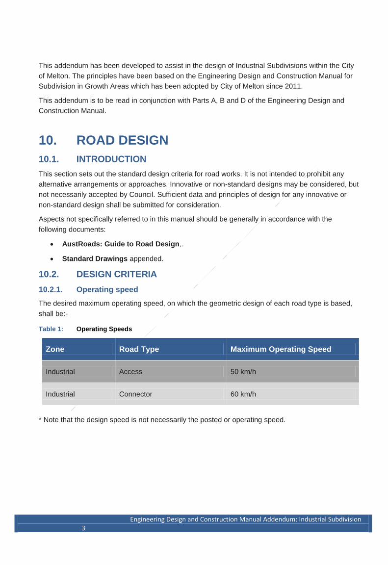
10.2.1. Operating speed
The desired maximum operating speed, on which the geometric design of each road type is based,
shall be:-
Table 1: Operating Speeds
Zone Road Type Maximum Operating Speed
Industrial Access 50 km/h
Industrial Connector 60 km/h
* Note that the design speed is not necessarily the posted or operating speed.
4 Engineering Design and Construction Manual Addendum: Industrial Subdivision
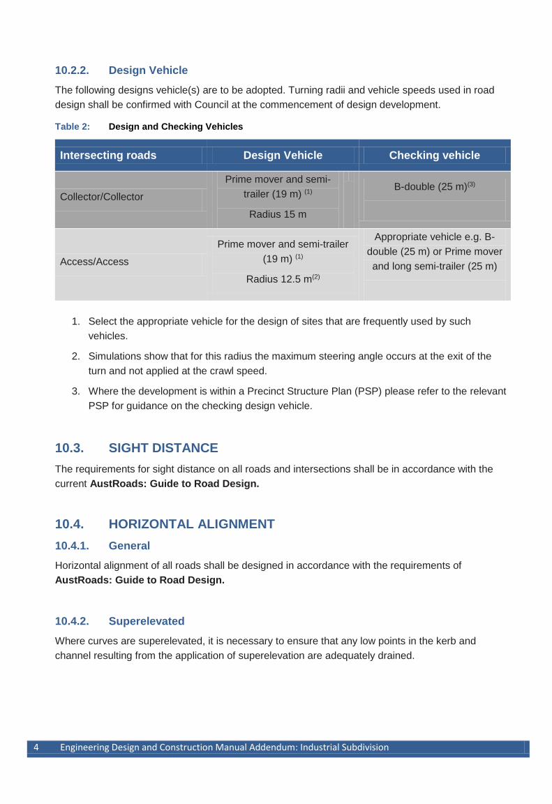
10.2.2. Design Vehicle
The following designs vehicle(s) are to be adopted. Turning radii and vehicle speeds used in road
design shall be confirmed with Council at the commencement of design development.
Table 2: Design and Checking Vehicles
Intersecting roads Design Vehicle Checking vehicle
Collector/Collector
Prime mover and semi-
trailer (19 m) (1)
Radius 15 m
B-double (25 m)(3)
Access/Access
Prime mover and semi-trailer
(19 m) (1)
Radius 12.5 m(2)
Appropriate vehicle e.g. B-
double (25 m) or Prime mover
and long semi-trailer (25 m)
1. Select the appropriate vehicle for the design of sites that are frequently used by such
vehicles.
2. Simulations show that for this radius the maximum steering angle occurs at the exit of the
turn and not applied at the crawl speed.
3. Where the development is within a Precinct Structure Plan (PSP) please refer to the relevant
PSP for guidance on the checking design vehicle.
10.3. SIGHT DISTANCE
The requirements for sight distance on all roads and intersections shall be in accordance with the
current AustRoads: Guide to Road Design.
10.4. HORIZONTAL ALIGNMENT
10.4.1. General
Horizontal alignment of all roads shall be designed in accordance with the requirements of
AustRoads: Guide to Road Design.
10.4.2. Superelevated
Where curves are superelevated, it is necessary to ensure that any low points in the kerb and
channel resulting from the application of superelevation are adequately drained.
Engineering design and Construction Manual Addendum: Industrial Subdivision 5
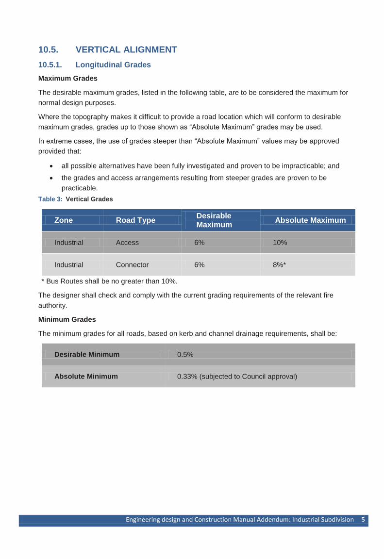
10.5. VERTICAL ALIGNMENT
10.5.1. Longitudinal Grades
Maximum Grades
The desirable maximum grades, listed in the following table, are to be considered the maximum for
normal design purposes.
Where the topography makes it difficult to provide a road location which will conform to desirable
maximum grades, grades up to those shown as “Absolute Maximum” grades may be used.
In extreme cases, the use of grades steeper than “Absolute Maximum” values may be approved
provided that:
all possible alternatives have been fully investigated and proven to be impracticable; and
the grades and access arrangements resulting from steeper grades are proven to be
practicable.
Table 3: Vertical Grades
Zone Road Type Desirable Maximum
Absolute Maximum
Industrial Access 6% 10%
Industrial Connector 6% 8%*
* Bus Routes shall be no greater than 10%.
The designer shall check and comply with the current grading requirements of the relevant fire
authority.
Minimum Grades
The minimum grades for all roads, based on kerb and channel drainage requirements, shall be:
Desirable Minimum 0.5%
Absolute Minimum 0.33% (subjected to Council approval)
6 Engineering Design and Construction Manual Addendum: Industrial Subdivision
10.5.2. Vertical Curves
General
A vertical curve, of parabolic form, shall be provided at every change of grade where the arithmetic
change of grade is more than:
Access and Collector 1.0%
Every effort should be made to provide lengthy vertical curves for improved appearance.
Generally, the minimum length of a vertical curve shall be 20m.
All vertical curves shall be designed in accordance with AustRoads: Guide to Road Design
10.6. STANDARD CROSS-SECTION
The standard cross section for various roads in new subdivisions shall be in accordance with the
relevant PSP for the area. Basis for the standard cross sections is outlined in the PSP Guidelines
and associated Road note/s.
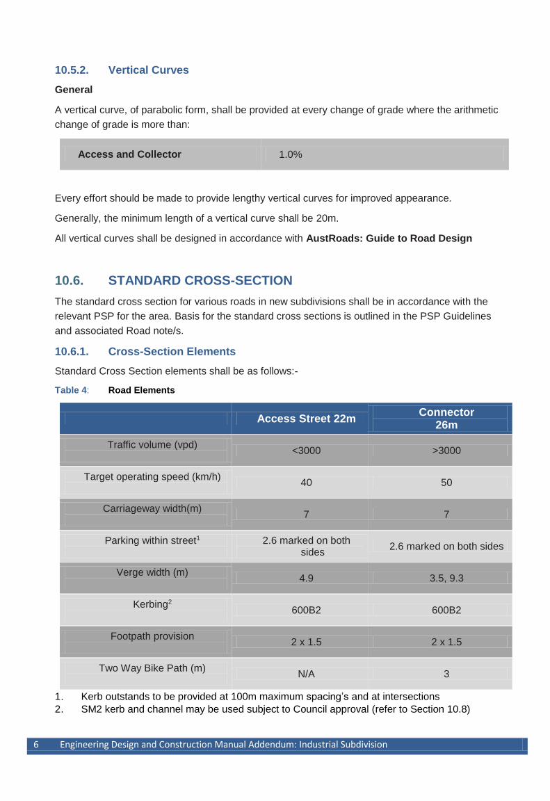
10.6.1. Cross-Section Elements
Standard Cross Section elements shall be as follows:-
Table 4: Road Elements
Access Street 22m Connector
26m
Traffic volume (vpd)
<3000 >3000
Target operating speed (km/h)
40 50
Carriageway width(m)
7 7
Parking within street1
2.6 marked on both sides
2.6 marked on both sides
Verge width (m)
4.9 3.5, 9.3
Kerbing2
600B2 600B2
Footpath provision
2 x 1.5 2 x 1.5
Two Way Bike Path (m)
N/A 3
1. Kerb outstands to be provided at 100m maximum spacing’s and at intersections
2. SM2 kerb and channel may be used subject to Council approval (refer to Section 10.8)
Engineering design and Construction Manual Addendum: Industrial Subdivision 7
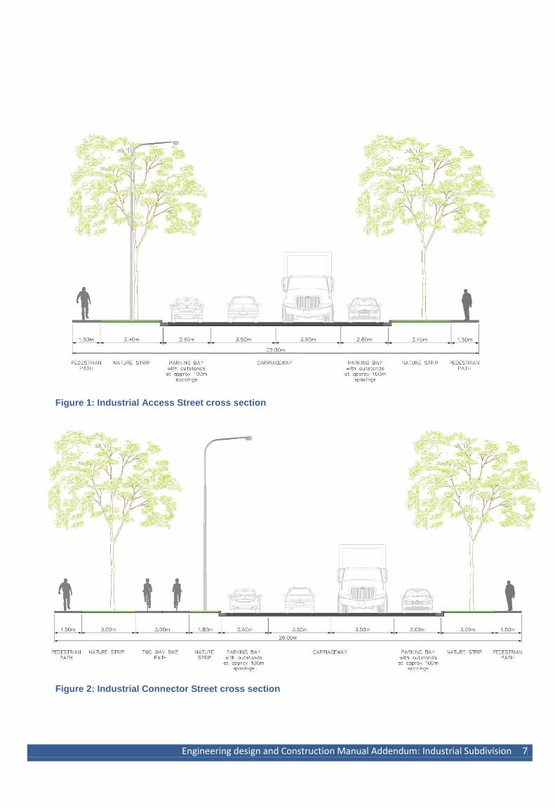
Figure 1: Industrial Access Street cross section
Figure 2: Industrial Connector Street cross section
8 Engineering Design and Construction Manual Addendum: Industrial Subdivision
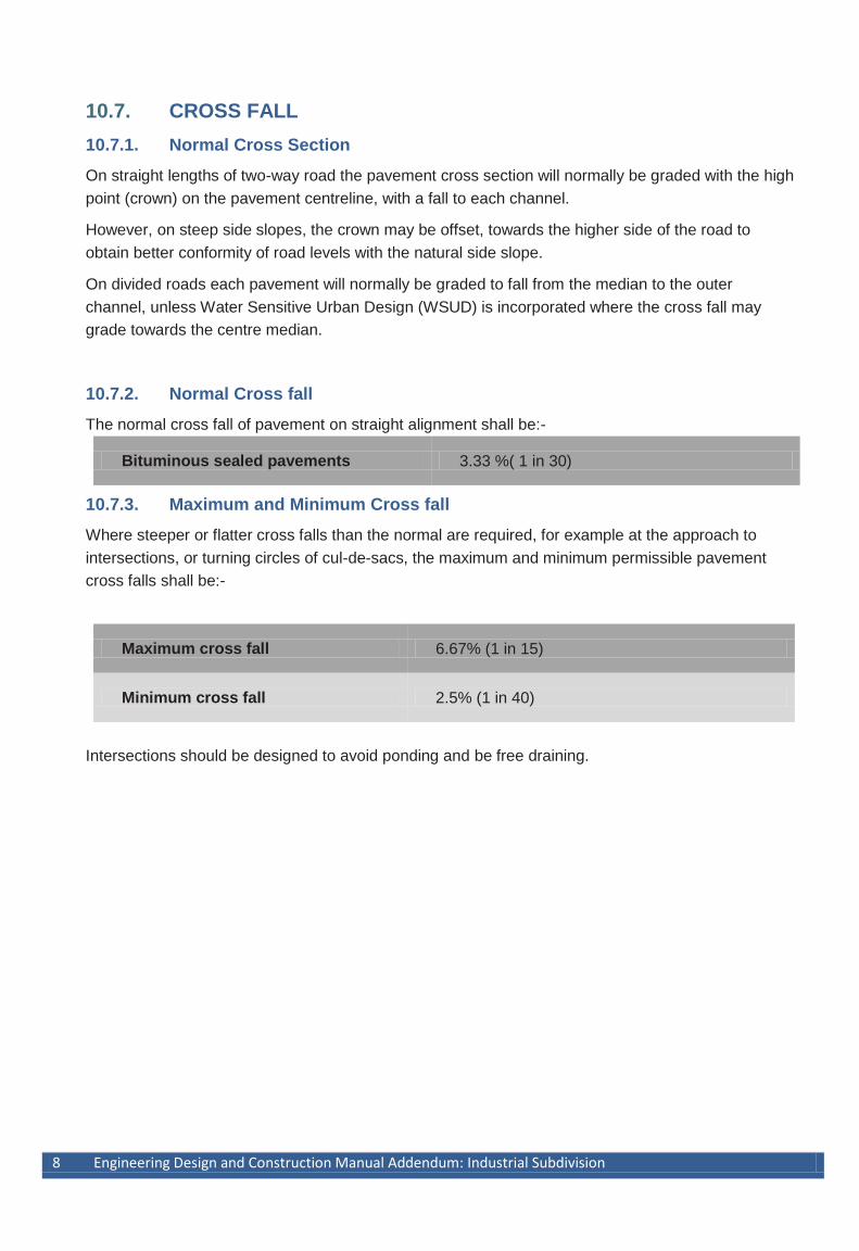
10.7. CROSS FALL
10.7.1. Normal Cross Section
On straight lengths of two-way road the pavement cross section will normally be graded with the high
point (crown) on the pavement centreline, with a fall to each channel.
However, on steep side slopes, the crown may be offset, towards the higher side of the road to
obtain better conformity of road levels with the natural side slope.
On divided roads each pavement will normally be graded to fall from the median to the outer
channel, unless Water Sensitive Urban Design (WSUD) is incorporated where the cross fall may
grade towards the centre median.
10.7.2. Normal Cross fall
The normal cross fall of pavement on straight alignment shall be:-
Bituminous sealed pavements 3.33 %( 1 in 30)
10.7.3. Maximum and Minimum Cross fall
Where steeper or flatter cross falls than the normal are required, for example at the approach to
intersections, or turning circles of cul-de-sacs, the maximum and minimum permissible pavement
cross falls shall be:-
Maximum cross fall 6.67% (1 in 15)
Minimum cross fall 2.5% (1 in 40)
Intersections should be designed to avoid ponding and be free draining.
Engineering design and Construction Manual Addendum: Industrial Subdivision 9
10.8. KERB AND CHANNEL
10.8.1. Location
Concrete kerb and channel shall be provided on both sides of all industrial roads.
10.8.2. Kerb and Channel Types
The standard kerb and channel profile shall be as shown on the Standard Drawings. In general
Barrier Kerb profiles are to be used in industrial developments
Exceptions to the use of these profiles may be considered in the following instances:-
Kerb only may be used with one-way cross fall pavements and reverse fall nature strip on
high side;
Medians & Traffic Islands, where semi-mountable is shown, shall be M2, M3, SM2 or SM3;
Roundabout outer kerbs shall be SM2 from TP to TP. Roundabout splitter islands are to be
SM3. Roundabout central island outer kerb shall be SM3;
For small islands (with an enclosed surface area not greater than 3m2) SM1 may be used;
10.8.3. Grading
General minimum kerb and channel grade shall be 0.5% (1 in 200); in exceptional circumstances a
0.3% grade may be used subject to Council approval.
Vertical curves should be as long a length as possible. Generally a minimum length of 20m shall be
used.
Where the change in grade in a vertical curve will result in excessively long flat areas, the invert
grade shall be extended through to the low point to provide a minimum 0.3% grade.
Designers shall limit crest curves that have minimum grade (0.3% to 0.5%) to between 30m and 50m
length.
In kerb returns the desirable minimum grade is 0.75% and absolute minimum is 0.50%.

10 Engineering Design and Construction Manual Addendum: Industrial Subdivision
10.8.4. Kerb Radii
Kerb radii shall allow for the nominated design vehicle to move through the swept path without
impedance.
The radius of the kerb and channel, measured to back of kerb, at an intersection shall be selected in
accordance with “Austroads Guide to Road Design Part 3 – Geometric Design” and current versions
of the “Austroads Design Vehicles and Turning Path Templates”.
Use of the Austroads template for a “Standard Service Vehicle” (19m) is recommended as the
governing criteria.
The following kerb radii are considered to be desirable minimums:
Industrial Access Street and Connector Street
12.50m
Engineering design and Construction Manual Addendum: Industrial Subdivision 11
10.9. FOOTPATHS & NATURE STRIPS
10.9.1. Cross-section
The cross-section of footpaths and nature strips shall conform to those shown on the current Melton
Council suite of Standard Drawings.
10.9.2. Cross fall
Where concrete footpath paving is to be provided within a street reserve, the footpath cross fall shall
be 2.0% towards the road. In all other instances concrete footpaths and shared paths shall have a
maximum cross fall of 2.5%.
Nature strip cross falls shall be within the range of 2.5% and 10.0%, towards the road.
Standard cross falls shall not be exceeded at any location where vehicular access to allotments may be required.
10.9.3. Provision of Tactile Ground Surface Indicators
Use of Tactile Ground Surface Indicators (TGSI) shall be in accordance with the Disability
Discrimination Act (DDA) requirements and any Council strategies for disabled access. The use of
TGSI will be minimised by designing for a continuous path of travel in order to avoid their need at
minor access street intersections. Changes of footpath direction at crossings are therefore
discouraged.
Footpath and Pram Crossings (kerb ramps) shall be provided in accordance with DDA requirements.
Location and alignment shall support the principle of “continuous path of travel” requirements.
TGSI are not required where:
The geometry of a kerb ramp at an intersection is fully compliant with AS1428.1; and
The ramp is located on the direct extension of the property line; and
The top of the ramp is no more than 3000mm from the intersection of property lines.
TGSI are required at all kerb ramps that do not comply with the above, at all mid-block crossings,
and at high usage vehicle crossovers, e.g. service stations and shopping centre car parks.
Directional TGSI are to be used where a kerb ramp is not located on the direct extension of the
property line in an accessible path of travel from the building / boundary line and will lead to warning
indicators installed at the crossing (kerb ramp) point.
Directional and warning TGSI will always be required at mid-block pedestrian or bus stops.
Refer to Melton Councils current Standard Drawings or particular requirements of the Precinct
Structure Plan.
10.9.4. Modification of the Footpath Cross fall
Modification of the footpath fall will only be considered in extreme circumstance; as this approach
may increase the catchment area discharging stormwater into the downhill lots, it shall be avoided
where possible.
Reverse fall (away from kerb) nature strips with footpath ‘spoon drain’ will only be considered in
extreme circumstances as this approach requires higher maintenance for drainage without

12 Engineering Design and Construction Manual Addendum: Industrial Subdivision
significant access benefits.
Engineering design and Construction Manual Addendum: Industrial Subdivision 13
10.10. CARRIAGEWAY
10.10.1. Offsetting of the Crown and one-way cross fall
In circumstances where the natural cross slope of the existing terrain will lead to unreasonably high
cut batters, offsetting the crown or one-way cross fall may be considered.
Offsetting of the crown, on a two-way road, is permissible, provided that sufficient stormwater
capacity is retained in the channel and roadway on the high side of the road. Required capacity will
depend on catchment, and on the spacing of storm water entry pits. Offset crown widths shall be
sufficient to ensure that the crown is able to be laid with asphalt machinery.
A pavement with one-way cross fall may be approved only where drainage requirements can be
adequately met.
10.10.2. Reverse Cross fall – Divided Roads
In extreme cases, reverse cross fall, on the uphill lane of divided roads, is permissible provided that
adequate drainage capacity is provided in the uphill median channel, and precautions taken to
intercept flow at median openings.
10.10.3. Median Cross fall
Median Cross fall, on divided roads, should desirably not exceed a maximum of 16% (1 in 6), with
33%(1 in 3) as an absolute maximum, unless a retaining wall is provided and there are no proposed
median breaks in the median.
At median openings however, the pavement cross fall shall not exceed 5% (1 in 20).
10.10.4. A Split-Level Road
Modification of the road section to accommodate a split level road will only be considered in extreme
circumstance.
14 Engineering Design and Construction Manual Addendum: Industrial Subdivision
10.11. VEHICULAR CROSSINGS
Vehicle crossings are not required to be provided unless they are required as a condition of the
Planning Permit. Where industrial vehicle crossings are provided they are to be in accordance with
Melton Councils Standard Drawings.
10.11.1. Driveway Grades
Where vehicle crossings are provided the desirable maximum driveway grade is 5% (1 in 20) for
industrial allotments. In steep terrain, driveway cut or fill earthworks into the allotments are to be
shown on the plans so that the driveway access is created with the subdivision works (where
required).
10.12. UTILITY ALLOCATIONS
The location of utility services is to be in accordance with the requirements of the relevant Council
and Service Authority. Further reference can be made to the Code of Practice for Management of
Infrastructure in Road Reserves
For clarity, typical cross sections showing service allocations are indicated in Appendix D of the
Engineering Design and Construction Manual.
Utility services are an important component of infrastructure provided for our newest suburbs.
Standard placement of utility services within road reserves ensures appropriate clearances and
access, while minimising conflicts between other road reserve infrastructure.
Layouts and road cross sections may need to be reviewed if non-standard trunk utilities are to be
provided because these utilities are typically larger infrastructure requiring larger clearances.
10.13. ROUNDABOUTS
Roundabouts shall be designed according to AustRoads Guide to Road Design.
Engineering design and Construction Manual Addendum: Industrial Subdivision 15
11. PAVEMENT DESIGN
11.1. SCOPE
The scope of this Section covers the design of pavements for Industrial subdivisions.
For asphalt pavement design, requirements are restricted to the design and construction of road
pavements with not less than two layers of asphalt and flanked by kerb and channel.
A minimum of two layers of asphalt has been adopted as the standard.
11.2. DESIGN REFERENCES
The design of the pavements shall be carried out by qualified engineering consultants in accordance
with this Manual and the principles, practices and procedures detailed in the following design
references:
VicRoads (Current). Code of Practice RC 500.22 : Code of Practice for Selection & Design of
Pavements & Surfacings. (RC 500.22);
VicRoads (Current). Code of Practice RC 500.20 : Assignment of CBR (Strength) and
Percent Swell to Earthworks and Pavement Materials. (RC 500.20)
VicRoads (Current). Standard Specifications for Roadworks & Bridgeworks. (VicRoads
Standard Specifications)
Austroads (Current). Guide To Pavement Technology - Part 2 : Pavement Structural Design.
Publication No. AGPT02/08. (AGPT02).
16 Engineering Design and Construction Manual Addendum: Industrial Subdivision
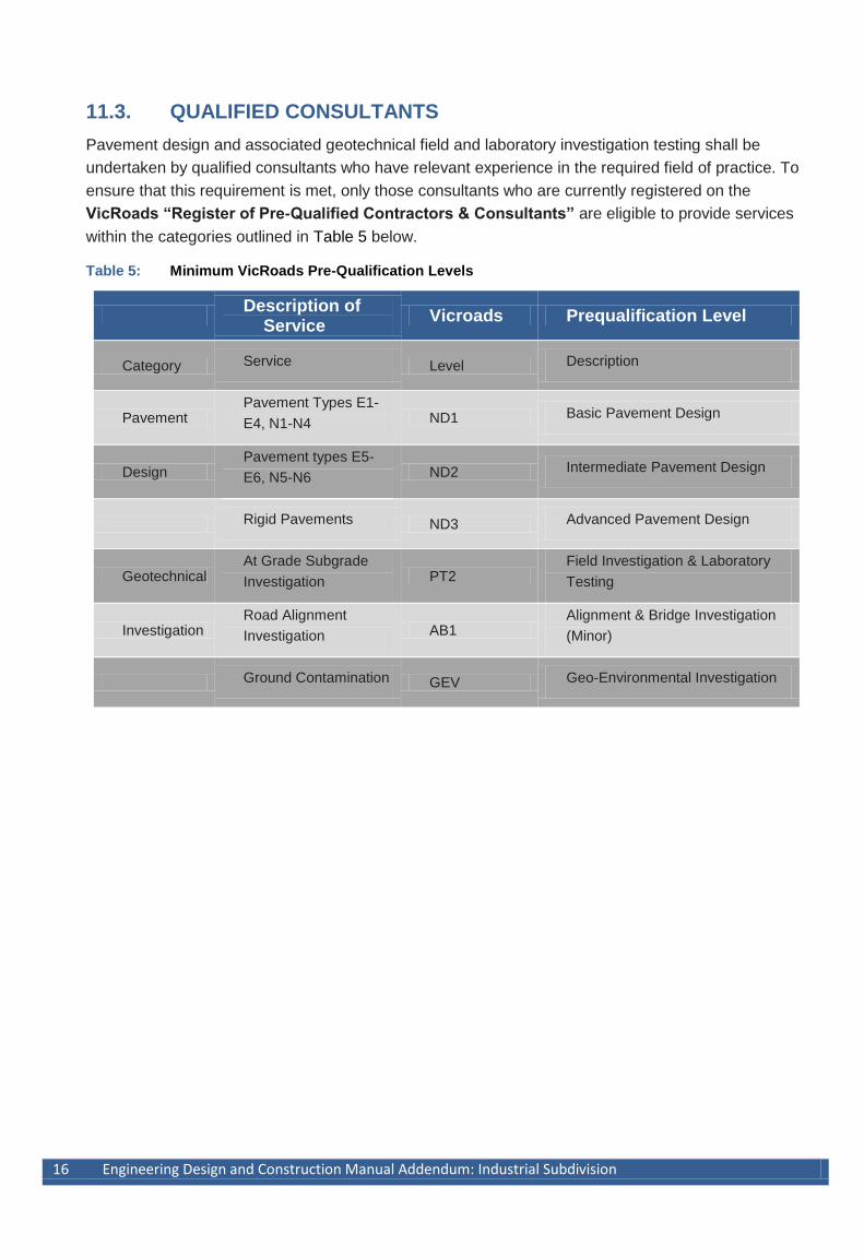
11.3. QUALIFIED CONSULTANTS
Pavement design and associated geotechnical field and laboratory investigation testing shall be
undertaken by qualified consultants who have relevant experience in the required field of practice. To
ensure that this requirement is met, only those consultants who are currently registered on the
VicRoads “Register of Pre-Qualified Contractors & Consultants” are eligible to provide services
within the categories outlined in Table 5 below.
Table 5: Minimum VicRoads Pre-Qualification Levels
Description of
Service Vicroads Prequalification Level
Category Service Level Description
Pavement Pavement Types E1-
E4, N1-N4 ND1 Basic Pavement Design
Design Pavement types E5-
E6, N5-N6 ND2 Intermediate Pavement Design
Rigid Pavements ND3 Advanced Pavement Design
Geotechnical At Grade Subgrade
Investigation PT2 Field Investigation & Laboratory
Testing
Investigation Road Alignment
Investigation AB1 Alignment & Bridge Investigation
(Minor)
Ground Contamination GEV Geo-Environmental Investigation
Engineering design and Construction Manual Addendum: Industrial Subdivision 17
11.4. PAVEMENT DESIGN PARAMETERS
11.4.1. General
The general aim of pavement design is to select the most economical pavement thickness and
composition which will provide a satisfactory level of service over the adopted design life taking into
account the prevailing subgrade conditions, the characteristics of the materials in the pavement and
the anticipated level of traffic.
The pavement design process accordingly requires that a number of input variables be selected and
assigned to any particular design. These design parameters are listed below, together with their
associated reference in this guide:
Project Reliability Level (Section 11.4.2)
Assignment of a Project Reliability Level for mechanistic pavement design purposes and
for design of rigid pavements.
Subgrade (Section 11.5)
Assignment of subgrade strength, its associated classification as expansive or otherwise,
capping layer fills, and subgrade improvement measures where required.
Pavement Materials (Section 11.6)
Selection and specification of appropriate pavement materials, their properties, and
assignment of associated characteristics to be used in the design process.
Design Traffic (Section 11.7)
Assessment of forecast future traffic for the required design period, including future
growth, the proportion of heavy vehicles and their associated loading characteristics.
18 Engineering Design and Construction Manual Addendum: Industrial Subdivision
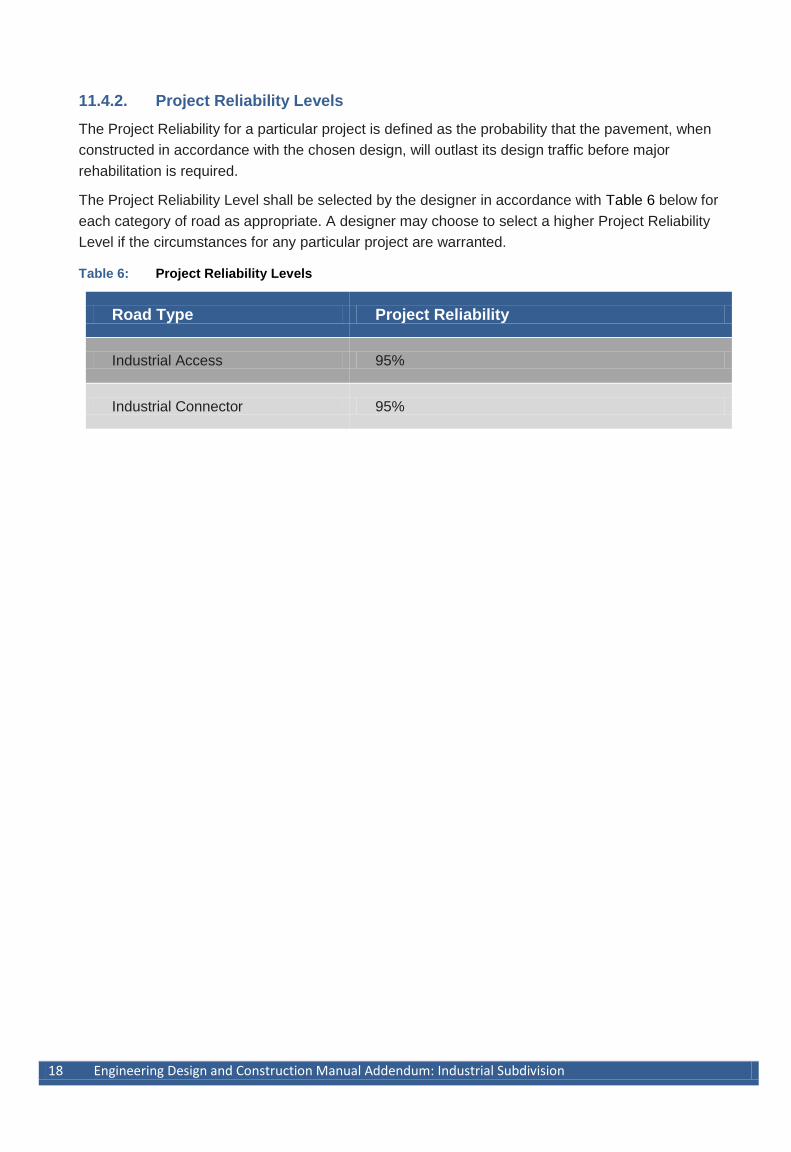
11.4.2. Project Reliability Levels
The Project Reliability for a particular project is defined as the probability that the pavement, when
constructed in accordance with the chosen design, will outlast its design traffic before major
rehabilitation is required.
The Project Reliability Level shall be selected by the designer in accordance with Table 6 below for
each category of road as appropriate. A designer may choose to select a higher Project Reliability
Level if the circumstances for any particular project are warranted.
Table 6: Project Reliability Levels
Road Type Project Reliability
Industrial Access 95%
Industrial Connector 95%
Engineering design and Construction Manual Addendum: Industrial Subdivision 19
11.5. SUBGRADE & EARTHWORKS
11.5.1. Subgrade Evaluation
Subgrade investigation testing, including both field and laboratory testing and associated evaluation
and determination of subgrade strength, shall be undertaken in accordance with all relevant
Australian Standards and relevant requirements of the following references in descending order:
VicRoads Manual of Codes of Practice, test methods and design guides;
Standards Australia test methods; and
Austroads Design Guides.
The scope, extent and location of investigation testing should be commensurate with the location
and magnitude of the proposed works. Notwithstanding the requirements outlined in the above
guides, the following minimum testing shall be undertaken for each project for the purpose of
characterising the nature and condition of the subgrade:
excavation of test bores or pits to a depth of at least 1.0 m or more than 0.5m below the
proposed subgrade (whichever is the greater), at intervals not exceeding 120 m, with a
minimum of 3 test sites on any one project;
dynamic cone penetrometer testing and measurement of field moisture content at each
test site;
grading and Atterberg limit testing on at least 2 representative samples of subgrade
material; and
laboratory soaked (4 day) CBR tests on at least 2 representative laboratory remoulded
samples of subgrade material.
If rock is encountered during the field investigation, the requirement to excavate bores or pits to a
depth of 1.0 m may be waived.
20 Engineering Design and Construction Manual Addendum: Industrial Subdivision
11.5.2. Maximum Subgrade Design CBR
To ensure that uniform minimum pavement design standards are met, the subgrade design CBR
assigned for pavement design purposes shall not exceed 10%.
11.5.3. Expansive Subgrades
Subgrade Classification
Subgrade materials with an assigned swell ≥ 2.5% as determined in accordance with RC 500.20
shall be classified as expansive for the purpose of this guide. These materials are categorised by
Austroads Guide to Pavement Technology part 2 (AGPT02)02 to be at the very least highly
expansive.
Treatment of Expansive Subgrades
Since expansive subgrades exhibit seasonal volume changes with resulting shape loss and
environmentally induced cracking, appropriate measures shall be incorporated into the design of the
pavement as outlined in RC 500.22 Section 5.2 and AGPT02 Section 5.3.5.
These shall include, without being limited to, incorporation of the following features into the design in
accordance with the referenced sections of this guide :
minimum total pavement thickness as specified herein;
provision of a capping layer as specified herein; and
attention to the placement of subsurface drainage as specified herein.
.
Engineering design and Construction Manual Addendum: Industrial Subdivision 21
11.5.4. Weak Subgrade
In addition to the pavement composition requirements outlined in this guide, an appropriate working
platform, or subgrade improvement layer, may need to be incorporated into the pavement structure
at the time of construction to facilitate placement and compaction of subsequent pavement layers.
The subgrade improvement layer may be incorporated into the pavement design in accordance with
the following guidelines:
subgrade design CBR of 2% or greater - the thickness of the working platform may be
included within the required overall pavement thickness provided that the materials
satisfy the requirements of this guide;
subgrade design CBR < 2% - the pavement thickness design may be based upon a
subgrade design CBR of 2%, provided that the subgrade is first improved to a depth of
not less than 150 mm and that the subgrade improvement layer is not incorporated into
the overall pavement thickness.
Where subgrade improvement layers are incorporated into the pavement structure, the usual
requirements for compaction shall apply. In the case of test rolling however, only the uppermost
improvement layer shall be required to be test rolled so as to withstand visible deformation and
springing. The requirement to test roll any underlying improvement layers, and subgrade, may be
waived.
Subgrade improvement is most often required because of the presence of unsuitable materials or the
presence of high moisture contents at the time of construction. In determining the need for
subgrade improvement, it is important to take into account the potential for the subgrade to be
weakened if drainage of the formation is inadequate during construction.
Any isolated small areas of subgrade which are weaker than the subgrade CBR assigned for design
of the pavement, or which are weak at the time of construction, shall be treated by excavation to a
sound base and backfilled to subgrade level with either of the following materials:
suitable surplus earthworks materials from the site; or
imported Type A capping layer material.
22 Engineering Design and Construction Manual Addendum: Industrial Subdivision
11.5.5. Type A Materials
Capping Layer
To ensure that long term environmental effects are minimised, a capping layer shall be placed
immediately above subgrades classified as being expansive. The capping layer shall comprise lower
subbase quality material, or in-situ stabilised material, or imported Type A capping layer material,
with the following additional properties :
assigned swell ≤ 1.5%; and
permeability ≤ 5 x 10⁻⁹ m/s.
In addition to the material properties outlined above, the capping layer shall have the following
minimum physical characteristics:
thickness ≥ 150 mm, or 2.5 times the maximum particle size of the capping layer
material, whichever is the greater; and
extend for a distance ≥ 0.6 m behind the back of kerb and channel, or the edge of the
pavement if there is no kerb and channel, except for arterial roads where the distance
shall be ≥ 1.5 m.
The capping layer may be included in the total thickness of unbound granular pavements (see
Section 11.5.4) if the laboratory soaked CBR of the material complies with the requirements for lower
subbase materials, or the following requirements.
Selected Material
All Type A selected material shall have an assigned swell ≤ 1.5%.
Unbound Granular Pavements
Where unbound granular pavements are designed for a subgrade design CBR of 2% and the total
pavement thickness ≥ 440 mm, as much as the lower 150 mm of the pavement may comprise the
following materials in lieu of lower subbase materials, provided that the material has a laboratory
soaked CBR ≥ 8%:
imported Type A capping layer material; or
imported Type A selected material; or
Engineering design and Construction Manual Addendum: Industrial Subdivision 23
11.6. PAVEMENT MATERIALS
11.6.1. General
Pavement materials shall be designed to be supplied, placed and compacted in accordance with the
version of the VicRoads Standard Specifications current at the time of commencing the pavement
design. The principal requirements relating to the following materials selected for pavements
designed in accordance with this guide are outlined in the sections below.
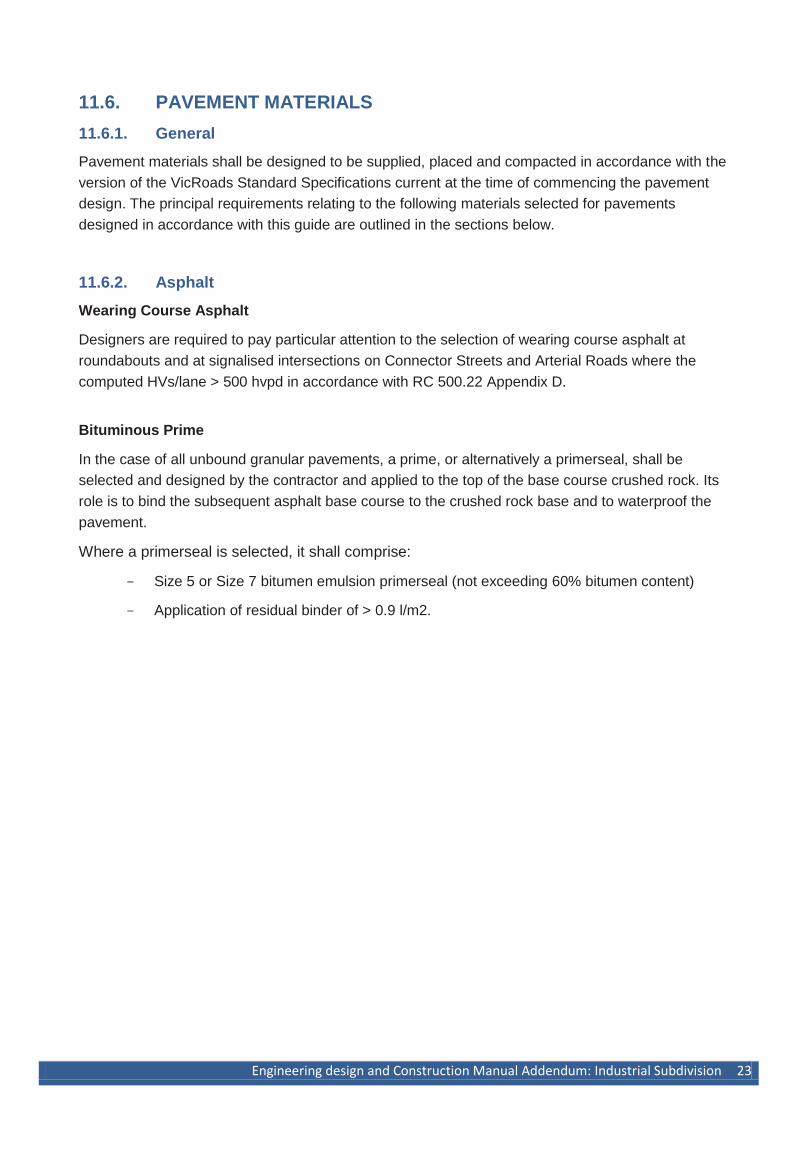
11.6.2. Asphalt
Wearing Course Asphalt
Designers are required to pay particular attention to the selection of wearing course asphalt at
roundabouts and at signalised intersections on Connector Streets and Arterial Roads where the
computed HVs/lane > 500 hvpd in accordance with RC 500.22 Appendix D.
Bituminous Prime
In the case of all unbound granular pavements, a prime, or alternatively a primerseal, shall be
selected and designed by the contractor and applied to the top of the base course crushed rock. Its
role is to bind the subsequent asphalt base course to the crushed rock base and to waterproof the
pavement.
Where a primerseal is selected, it shall comprise:
Size 5 or Size 7 bitumen emulsion primerseal (not exceeding 60% bitumen content)
Application of residual binder of > 0.9 l/m2.
24 Engineering Design and Construction Manual Addendum: Industrial Subdivision
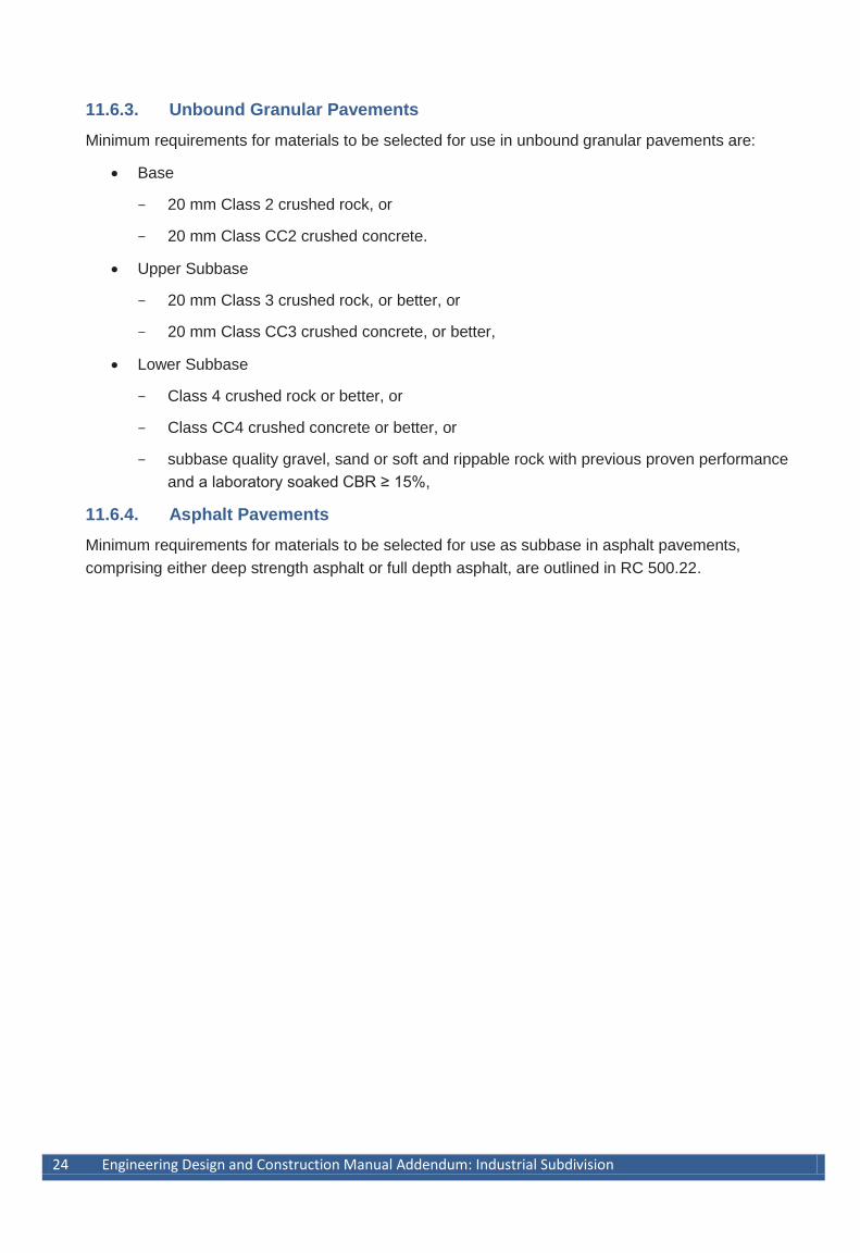
11.6.3. Unbound Granular Pavements
Minimum requirements for materials to be selected for use in unbound granular pavements are:
Base
20 mm Class 2 crushed rock, or
20 mm Class CC2 crushed concrete.
Upper Subbase
20 mm Class 3 crushed rock, or better, or
20 mm Class CC3 crushed concrete, or better,
Lower Subbase
Class 4 crushed rock or better, or
Class CC4 crushed concrete or better, or
subbase quality gravel, sand or soft and rippable rock with previous proven performance
and a laboratory soaked CBR ≥ 15%,
11.6.4. Asphalt Pavements
Minimum requirements for materials to be selected for use as subbase in asphalt pavements,
comprising either deep strength asphalt or full depth asphalt, are outlined in RC 500.22.
Engineering design and Construction Manual Addendum: Industrial Subdivision 25
11.7. DESIGN TRAFFIC
11.7.1. Design Period
Calculation of Design Traffic shall be based upon a minimum design period of 20 years. A
designer may choose to select a longer design period if the circumstances for any particular project
are warranted.
11.7.2. Calculation of Design Traffic
Calculation of Design Traffic shall be undertaken in accordance with VicRoads Code of Practice:
Selection and Design of Pavements and Surfacings RC 500.22 and Austroads Guide to Pavement
Technology: Pavement Structural Design to suit the characteristics and requirements of each
particular project. In addition to the design period outlined above, the calculations will require an
appropriate assessment of the following input data :
forecast total traffic over the duration of the design period, including any necessary provision for future traffic growth;
the proportion of heavy vehicles, including waste management vehicles, and an allowance for buses where the street will form part of a bus route;
heavy vehicle traffic generated by construction during development of subdivisions in the case of Access Streets;
vehicular trafficking patterns including the directional split, vehicle wander on wide pavements and lane distribution on multi-lane roads; and
heavy vehicle load factors, incorporating the average number of HVAG per HV, and the average number of ESA per HVAG in the case of flexible pavements.
Typical Design Traffic parameters are outlined in Appendix B of the Engineering Design and
Construction Manual and are provided as a guide only. The data shall not be used as a substitute for
the designer making an assessment of relevant parameters for each particular project, particularly in
the case of industrial subdivisions where detailed heavy vehicle traffic forecasts are necessary.
Where the width of a street, or the presence of parked vehicles, results in two way traffic either
partially or fully using the same travel path, consideration needs to be given to assignment of the
appropriate Direction Factor, required to be within the range of 0.5 to 1.0.
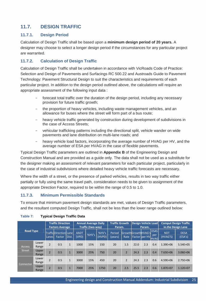
11.7.3. Minimum Permissible Standards
To ensure that minimum pavement design standards are met, values of Design Traffic parameters,
and the resultant computed Design Traffic, shall not be less than the lower range outlined below:
Table 7: Typical Design Traffic Data
Road Type
Traffic Direction Factors Average
Annual Average Daily Traffic (two-way)
Traffic Growth Param.
Design Vehicle Load Param.
Comput Design Traffic in.the Design Lane
Traffic Lanes
Direction Factor
Lane Dist.
AADT (VPD)
%HV's %HV's (HVPD)
Period (years)
Growth Rate
Growth Factor
HVAG's per HV
ESAS per
HVAG
NDT (HVAG'S)
DESA (ESA's)
Access Street
Lower Range
2 0.5 1 1000 15% 150 20 1.5 22.0 2.3 0.4 1.39E+06 5.54E+05
Upper Range
2 0.5 1 3000 25% 750 20 2 24.3 2.3 0.4 7.65E+06 3.06E+06
Connector
Lower Range
2 0.5 1 3000 15% 450 20 2 24.3 2.3 0.6 4.59E+06 2.75E+06
Upper Range
2 0.5 1 7000 25% 1750 20 2.5 25.5 2.3 0.6 1.87E+07 1.12E+07
26 Engineering Design and Construction Manual Addendum: Industrial Subdivision
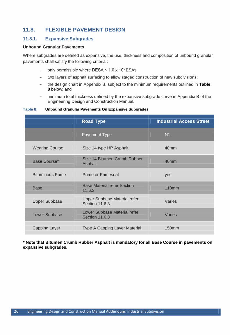
11.8. FLEXIBLE PAVEMENT DESIGN
11.8.1. Expansive Subgrades
Unbound Granular Pavements
Where subgrades are defined as expansive, the use, thickness and composition of unbound granular
pavements shall satisfy the following criteria :
only permissible where DESA ≤ 1.0 x 10⁶ ESAs;
two layers of asphalt surfacing to allow staged construction of new subdivisions;
the design chart in Appendix B, subject to the minimum requirements outlined in Table 8 below; and
minimum total thickness defined by the expansive subgrade curve in Appendix B of the Engineering Design and Construction Manual.
Table 8: Unbound Granular Pavements On Expansive Subgrades
Road Type Industrial Access Street
Pavement Type N1
Wearing Course Size 14 type HP Asphalt 40mm
Base Course* Size 14 Bitumen Crumb Rubber Asphalt
40mm
Bituminous Prime Prime or Primeseal yes
Base Base Material refer Section 11.6.3
110mm
Upper Subbase Upper Subbase Material refer Section 11.6.3
Varies
Lower Subbase Lower Subbase Material refer Section 11.6.3
Varies
Capping Layer Type A Capping Layer Material 150mm
* Note that Bitumen Crumb Rubber Asphalt is mandatory for all Base Course in pavements on expansive subgrades.

Engineering design and Construction Manual Addendum: Industrial Subdivision 27
Asphalt Pavements
Where subgrades are defined as expansive, the use, thickness and composition of asphalt
pavements, comprising either deep strength asphalt or full depth asphalt as defined by RC 500.22,
shall satisfy the following criteria:
mandatory where DESA >1.0 x 10⁶ ESA;
Section 11 and Appendix D of RC 500.22, subject to the minimum requirements outlined in Table 9 below; and
minimum total thickness defined by Figure 5.1 of RC 500.22, or by the expansive subgrade curve in Appendix B where DESA < 1.0 x 10⁶ ESA.
Table 9: Asphalt Pavements on Expansive Subgrades
Road Type Industrial Connector and Access
Street
Pavement Type N2
Max Permissible DESA (ESA) No Limit
Wearing Course
Size 14 Type H Asphalt 40mm
Intermediate Course
Size 20 Type SI Asphalt (or Type SS)
(varies) 75mm min
Base Course
Size 20 Type SI Asphalt (or Type SF)
75mm min
Subbase (Cementitious and/or unbound materials)
(varies)
Capping Layer
Type A Capping Layer Material 150mm min
28 Engineering Design and Construction Manual Addendum: Industrial Subdivision
11.8.2. Pavement Design Speeds
Unbound Granular Pavements
In view of the requirement for unbound granular pavements to be surfaced with two layers of asphalt
as specified in Sections 11.8.1 and 11.8.2 above, the Granular Pavement Design Chart in Appendix
B has been derived from mechanistic design procedures using CIRCLY on the basis of the following
pavement design parameters:
Project Reliability Level of 95%;
Pavement Design Speeds of both 10 km/h and 40 km/h, applicable for a designated speed
limit of up to 60 km/h.
If there are circumstances for a particular project where the use of parameters other than those
outlined above is warranted, designers will need to check their proposed designs in order to satisfy
any necessary alternative design criteria.
This is particularly important in relation to the adoption of pavement design speeds as specified in
VicRoads Code of Practice: Selection and Design of Pavements and Surfacings RC 500.22 for
designated speed limits > 60 km/h. For the unbound granular pavements outlined in this guide, there
would be a detrimental effect on the fatigue life of the asphalt surfacing because of the consequential
elastic layer properties required to be used in the mechanistic design process.
Asphalt Pavements
Asphalt pavements, comprising either deep strength asphalt or full depth asphalt as defined by RC
500.22, will require thickening where the pavement is located in the following locations:
at roundabouts and at signalised intersections; or
where the designated speed limit is ≤ 40 km/h.
Designers are also required to pay particular attention to the selection of wearing course asphalt on
Connector Streets and Arterial Roads in these locations where the computed HVs/lane > 500 hvpd in
accordance with VicRoads Code of Practice: Selection and Design of Pavements and Surfacings RC
500.22.
Engineering design and Construction Manual Addendum: Industrial Subdivision 29
11.9. SUBSURFACE PAVEMENT DRAINS
11.9.1. General
Subsurface pavement drains shall be provided in association with all kerb and channel. The design
and location of drains or filter blankets shall be carried out in accordance with the requirements of
VicRoads Code of Practice: Selection and Design of Pavements and Surfacings RC 500.22.
11.9.2. Expansive Subgrades
Where the subgrade is classified as being expansive, subsurface pavement drains shall be designed
to be contained wholly within the capping layer. In addition, no part of the subsurface drainage trench
shall be located within 150 mm of the underlying subgrade. If necessary, the capping layer may have
to be thickened to satisfy this requirement.

30 Engineering Design and Construction Manual Addendum: Industrial Subdivision
12. EARTHWORKS DESIGN
12.1. GENERAL
Objectives which should be met for earthworks and lot filling are:
To ensure that development does not cause or aggravate flooding of other properties by
filling land or undertaking other flood diversion works;
To ensure that buildings are located on a natural surface above the 1% AEP flood level or on
approved filled ground, so as to comply with the constraints of the Building Regulations 1994
and the Health Act;
To ensure that the recommendations of the Catchment Management Authorities or other
relevant agencies or organisations are complied with;
To ensure earthworks and lot filling activities do not result in the spread of noxious weeds, as
per Section 70A and 71 of the Catchment Management and Land Protection Act 1994;
To ensure that earthworks and lot filling works does not result in erosion dust, mud or debris
leaving the site; and
To maintain privacy and security of adjacent landowners.
12.2. PLANNING & ENGINEERING REQUIREMENTS
Typical earthworks may include lot filling or the construction of open drainage systems, levees,
access tracks, flood protection devices overland flow paths and vegetation removal.
Assessment of design submissions should focus on the above objectives and achievement of
suitable road and drainage systems. Engineering approval does not negate the need for planning
approval of such earthworks.
For any earthworks that are separate from subdivision works a planning permit shall be obtained and
engineering plans submitted for approval shall be accompanied by a construction specification.
Where works are to be staged it is recommended that consideration be given to the entire site and
not individual stages. This will eliminate the need for multiple planning permits.
Existing depressions shall not be filled unless the consent of the Relevant Authority is given in
writing, and any required permits obtained.
Engineering design and Construction Manual Addendum: Industrial Subdivision 31
12.3. EARTHWORKS AND FILLING REQUIREMENTS
The following earthworks and lot filling requirements apply to all developments:
All allotments shall be graded from either the rear to front or front to rear, by cutting or filling,
such that a desirable minimum grade of 0.67% (1:150) is achieved from the high point of the
allotment toward the low side of the allotment having the drainage outlet; an absolute
minimum grade of 0.5% (1 in 200) will be considered in extreme circumstances. Grades shall
be calculated along the side boundary of the allotment.
The finished floor level of all buildings shall be a minimum of 300mm above the 1% AEP flood
level, or as otherwise specified in the planning permit or by the responsible drainage
authority;
The extent and depth of all proposed filling shall be shown on construction plans. Where
depths of fill on allotments exceeds 200 mm, those areas are to be clearly differentiated from
fill of depth less than 200mm;
Full records shall be kept of all areas filled. The areas filled, the depths of fill and the finished
surface levels shall be recorded on the “as constructed’ plans. Refer to Part D of the
Engineering Design and Construction Manual for additional details regarding construction;
Details of the safety and integrity of any structure shall be provided to the Council where
earthworks abut structures;
The desirable maximum depth of fill allowable against fencing is 200mm provided a suitable
plinth is provided at the bottom of the fencing;
Retaining walls are required when the depth of fill exceeds 500mm or maximum batter slopes
are exceeded. Prior to designing retaining walls, the designer should discuss their proposal
with Council;
Concentrated stormwater runoff must not flow onto adjoining properties;
Natural overland flow paths in adjoining properties must be accommodated and any
restriction or alteration must not cause detriment to adjoining properties; and
All reasonable precautions must be taken to prevent the spread of noxious weeds from or to
the worksite.

32 Engineering Design and Construction Manual Addendum: Industrial Subdivision
13. DRAINAGE DESIGN
13.1. INTRODUCTION
This section of the Manual outlines the relevant standards necessary to meet best practice and
accommodate various needs in relation to the design and construction of stormwater systems, and
more generally to ensure the management of stormwater fits within an overall integrated water
management approach for industrial subdivision development.
Innovative or non-standard approaches to design may be considered subject to sufficient data and
supporting details being provided on the philosophy and principles that are proposed.
The drainage design shall:
Incorporate water quality and water quantity treatment measures to enhance quality of the
drainage runoff before discharging it to a creek or other main drainage network; and
Maintain pre-development flows at the outlet from the subdivision, unless otherwise approved
by the responsible drainage authority.
Council is the responsible authority for all drainage works outside the authority of the relevant
regional catchment management authority. All cross drainage works on creeks and waterways shall
be to the approval of the regional catchment management authority. For other minor and major
drainage, Council is the responsible drainage authority.
13.1.1. Stormwater and Water Sensitive Urban Design (WSUD)
Where the industrial subdivision is required to provide WSUD under the planning permit it shall be
designed and constructed to meet the following current best practice performance objectives for
stormwater quality as contained in the Urban Stormwater – Best Practice Environment Management
Guidelines (1999):
80% retention of the typical annual load of total suspended solids
45% retention of the typical annual load of total phosphorus; and
45% retention of the typical annual load of total nitrogen
Please refer to the Water Sensitive Urban Design Guidelines addendum for Melton Council for
further information particular to Melton.
13.1.2. Melbourne Water Stormwater Offset Contribution
Melbourne Water operates a stormwater offset service which involves a financial contribution paid by
developers for stormwater management works to be undertaken in another location when the
development cannot meet best practice of stormwater quality treatment. These works ‘offset’
stormwater impacts not treated within the development.
Stormwater offset contributions apply primarily for areas outside of drainage schemes. However,
some drainage schemes also include a stormwater offset rate.
Please refer to Melbourne Water for further information

Engineering design and Construction Manual Addendum: Industrial Subdivision 33
13.1.3. Drainage Design References
Design and construction of stormwater management systems for industrial development needs to be
in accordance with the current edition/version of the following documents:
“Urban Stormwater – Best Practice Environmental Management Guideline”, EPA, CSIRO,
Melbourne Water et all;
“Australian Runoff Quality Guidelines”, Engineers Australia;
“Australian Rainfall and Runoff”, Institution of Engineers Australia, (AR&R);
“Land Development Manual”, Melbourne Water;
“Drainage Design Guidelines”, VicRoads; and
“Design for Installation of buried concrete pipes” AS 3725.
13.2. PLANNING & LAYOUT
Where required in proposed developments, the drainage system shall accommodate runoff from the
upstream catchment, and provide for downstream drainage works.
Council and regional catchment management authority schemes shall be shown on plans.
Main drains should follow the valleys in reasonably straight alignments, with a minimum of deviation.
Natural drainage paths shall be preserved, in the form of roadways, parkland, walkways, etc., and
shall have a discharge capacity at least equal to that of the pipe drain.
Private allotments will not be permitted downstream of low points in roadways, downhill
court bowls, or any other locations where drainage flows may concentrate.
Gap flows shall be confined to roadways and reserves and under no circumstances encroach onto
private allotments.
34 Engineering Design and Construction Manual Addendum: Industrial Subdivision
13.3. COMPUTATION OF RUNOFF
Computation of runoff shall be determined using the Rational Method:
Where Q = CIA/360
Q = design discharge (m3/s)
C = runoff coefficient
I = rainfall intensity (mm/h)
A = catchment area (ha)
For large catchments the designer shall be responsible for ensuring that possible ‘Partial Area
Effects’ are taken into account when calculating peak flows using the Rational Method.
Hydraulic programs using other than the Rational Formula may be permitted by Council.
13.4. RAINFALL INTENSITY
Australian Rainfall and Runoff shall be used to calculate rainfall intensities for the relevant
location.
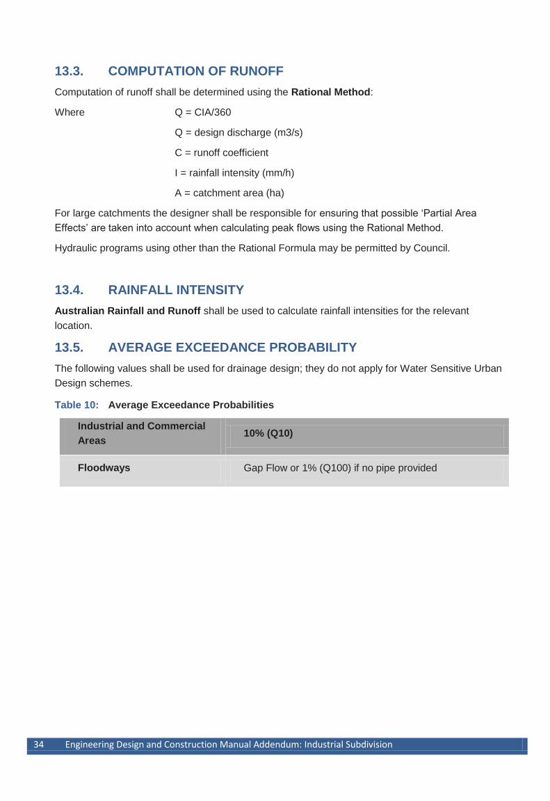
13.5. AVERAGE EXCEEDANCE PROBABILITY
The following values shall be used for drainage design; they do not apply for Water Sensitive Urban
Design schemes.
Table 10: Average Exceedance Probabilities
Industrial and Commercial
Areas 10% (Q10)
Floodways Gap Flow or 1% (Q100) if no pipe provided
Engineering design and Construction Manual Addendum: Industrial Subdivision 35
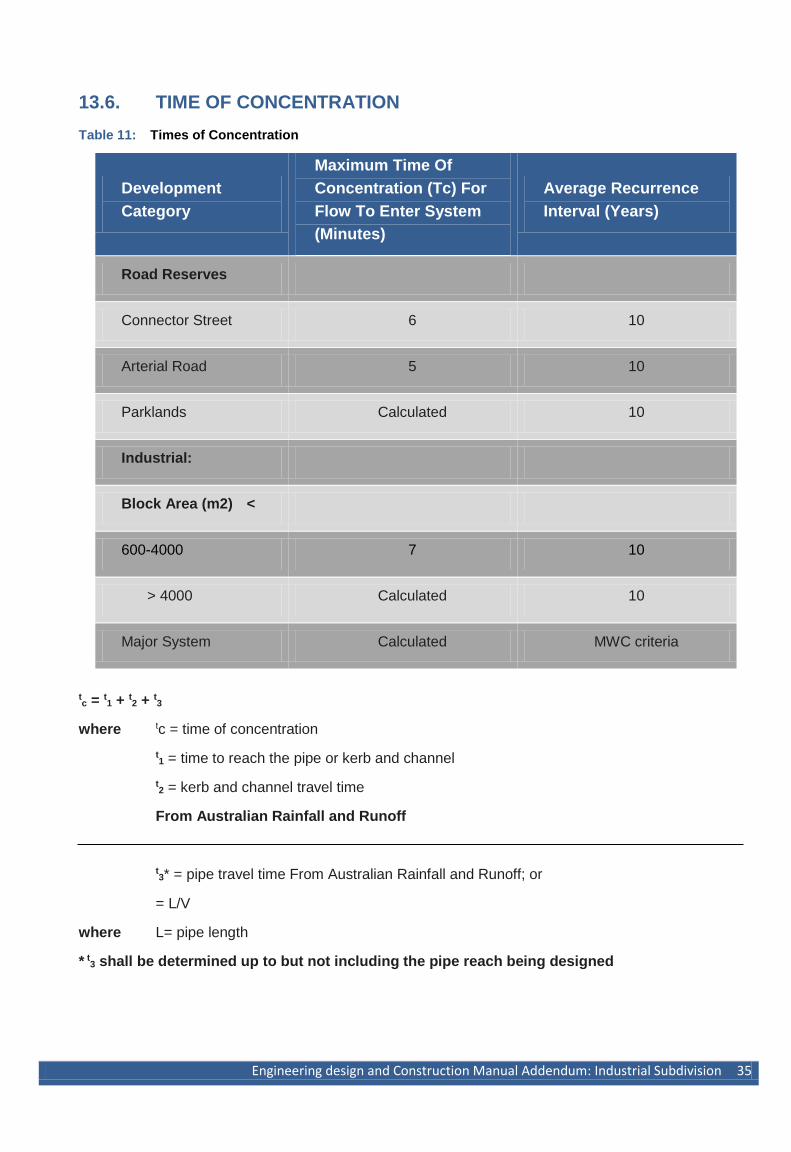
13.6. TIME OF CONCENTRATION
Table 11: Times of Concentration
Development
Category
Maximum Time Of
Concentration (Tc) For
Flow To Enter System
(Minutes)
Average Recurrence
Interval (Years)
Road Reserves
Connector Street 6 10
Arterial Road 5 10
Parklands Calculated 10
Industrial:
Block Area (m2) <
600-4000 7 10
> 4000 Calculated 10
Major System Calculated MWC criteria
tc = t1 + t2 + t3
where tc = time of concentration
t1 = time to reach the pipe or kerb and channel
t2 = kerb and channel travel time
From Australian Rainfall and Runoff
t3* = pipe travel time From Australian Rainfall and Runoff; or
= L/V
where L= pipe length
* t3 shall be determined up to but not including the pipe reach being designed
36 Engineering Design and Construction Manual Addendum: Industrial Subdivision
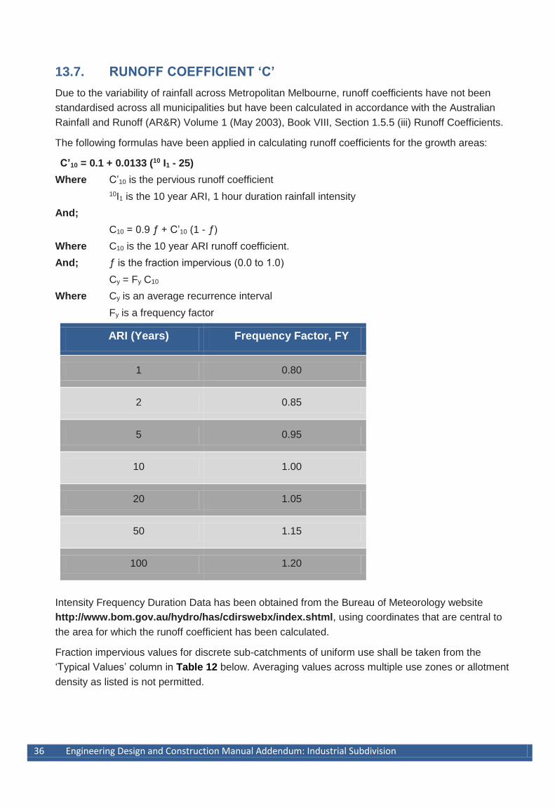
13.7. RUNOFF COEFFICIENT ‘C’
Due to the variability of rainfall across Metropolitan Melbourne, runoff coefficients have not been
standardised across all municipalities but have been calculated in accordance with the Australian
Rainfall and Runoff (AR&R) Volume 1 (May 2003), Book VIII, Section 1.5.5 (iii) Runoff Coefficients.
The following formulas have been applied in calculating runoff coefficients for the growth areas:
C’10 = 0.1 + 0.0133 (10 I1 - 25)
Where C’10 is the pervious runoff coefficient
10I1 is the 10 year ARI, 1 hour duration rainfall intensity
And;
C10 = 0.9 ƒ + C’10 (1 - ƒ)
Where C10 is the 10 year ARI runoff coefficient.
And; ƒ is the fraction impervious (0.0 to 1.0)
Cy = Fy C10
Where Cy is an average recurrence interval
Fy is a frequency factor
ARI (Years) Frequency Factor, FY
1 0.80
2 0.85
5 0.95
10 1.00
20 1.05
50 1.15
100 1.20
Intensity Frequency Duration Data has been obtained from the Bureau of Meteorology website
http://www.bom.gov.au/hydro/has/cdirswebx/index.shtml, using coordinates that are central to
the area for which the runoff coefficient has been calculated.
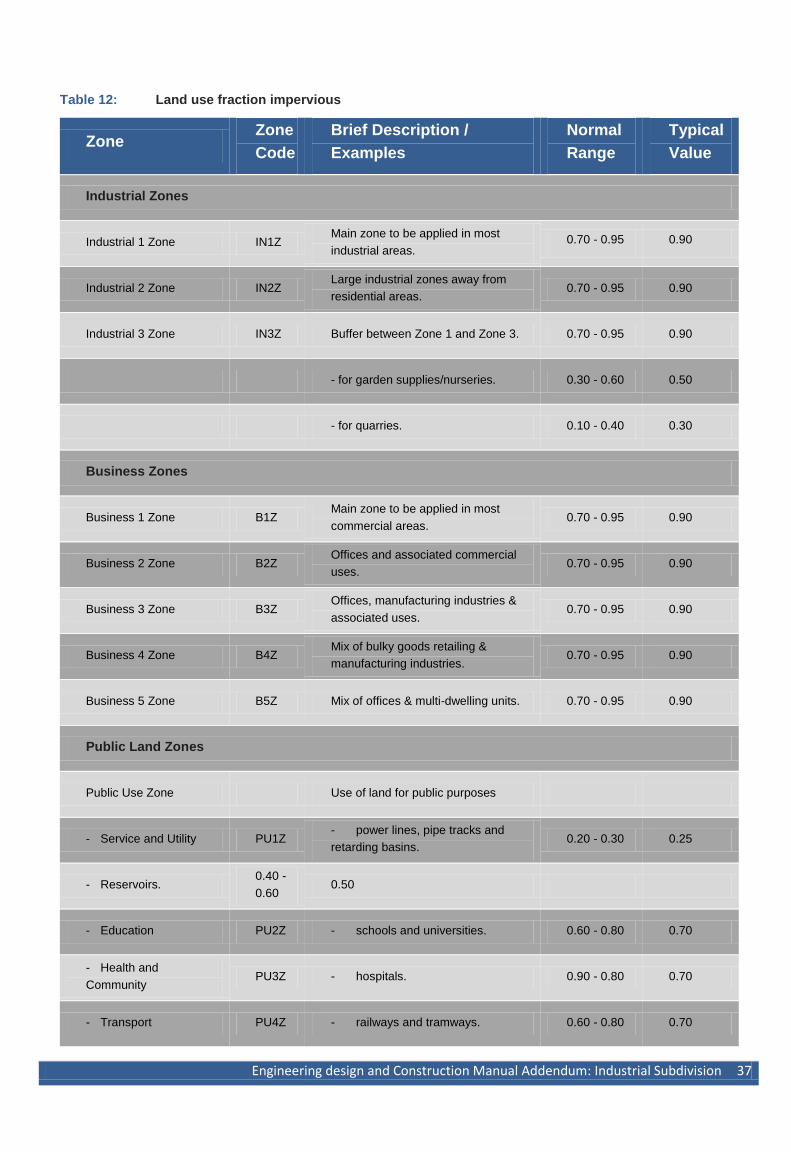
Fraction impervious values for discrete sub-catchments of uniform use shall be taken from the
‘Typical Values’ column in Table 12 below. Averaging values across multiple use zones or allotment
density as listed is not permitted.
Engineering design and Construction Manual Addendum: Industrial Subdivision 37
Table 12: Land use fraction impervious
Zone Zone
Code
Brief Description /
Examples
Normal
Range
Typical
Value
Industrial Zones
Industrial 1 Zone IN1Z Main zone to be applied in most
industrial areas. 0.70 - 0.95 0.90
Industrial 2 Zone IN2Z Large industrial zones away from
residential areas. 0.70 - 0.95 0.90
Industrial 3 Zone IN3Z Buffer between Zone 1 and Zone 3. 0.70 - 0.95 0.90
- for garden supplies/nurseries. 0.30 - 0.60 0.50
- for quarries. 0.10 - 0.40 0.30
Business Zones
Business 1 Zone B1Z Main zone to be applied in most
commercial areas. 0.70 - 0.95 0.90
Business 2 Zone B2Z Offices and associated commercial
uses. 0.70 - 0.95 0.90
Business 3 Zone B3Z Offices, manufacturing industries &
associated uses. 0.70 - 0.95 0.90
Business 4 Zone B4Z Mix of bulky goods retailing &
manufacturing industries. 0.70 - 0.95 0.90
Business 5 Zone B5Z Mix of offices & multi-dwelling units. 0.70 - 0.95 0.90
Public Land Zones
Public Use Zone Use of land for public purposes
- Service and Utility PU1Z - power lines, pipe tracks and
retarding basins. 0.20 - 0.30 0.25
- Reservoirs. 0.40 -
0.60 0.50
- Education PU2Z - schools and universities. 0.60 - 0.80 0.70
- Health and
Community PU3Z - hospitals. 0.90 - 0.80 0.70
- Transport PU4Z - railways and tramways. 0.60 - 0.80 0.70
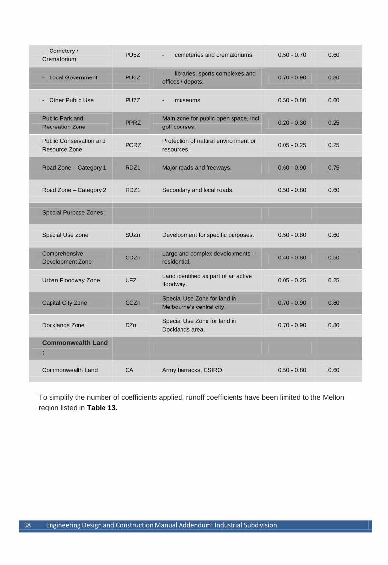
38 Engineering Design and Construction Manual Addendum: Industrial Subdivision
- Cemetery /
Crematorium PU5Z - cemeteries and crematoriums. 0.50 - 0.70 0.60
- Local Government PU6Z - libraries, sports complexes and
offices / depots. 0.70 - 0.90 0.80
- Other Public Use PU7Z - museums. 0.50 - 0.80 0.60
Public Park and
Recreation Zone PPRZ
Main zone for public open space, incl
golf courses. 0.20 - 0.30 0.25
Public Conservation and
Resource Zone PCRZ
Protection of natural environment or
resources. 0.05 - 0.25 0.25
Road Zone – Category 1 RDZ1 Major roads and freeways. 0.60 - 0.90 0.75
Road Zone – Category 2 RDZ1 Secondary and local roads. 0.50 - 0.80 0.60
Special Purpose Zones :
Special Use Zone SUZn Development for specific purposes. 0.50 - 0.80 0.60
Comprehensive
Development Zone CDZn
Large and complex developments –
residential. 0.40 - 0.80 0.50
Urban Floodway Zone UFZ Land identified as part of an active
floodway. 0.05 - 0.25 0.25
Capital City Zone CCZn Special Use Zone for land in
Melbourne’s central city. 0.70 - 0.90 0.80
Docklands Zone DZn Special Use Zone for land in
Docklands area. 0.70 - 0.90 0.80
Commonwealth Land
:
Commonwealth Land CA Army barracks, CSIRO. 0.50 - 0.80 0.60
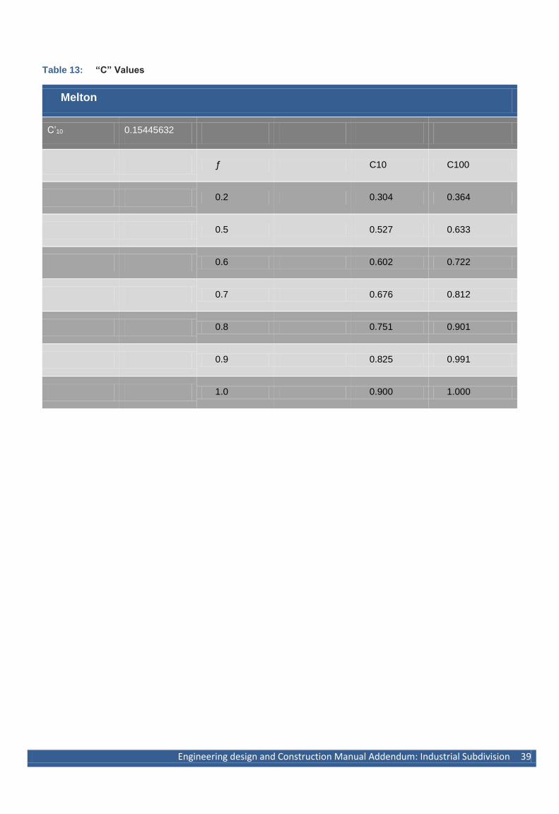
To simplify the number of coefficients applied, runoff coefficients have been limited to the Melton
region listed in Table 13.
Engineering design and Construction Manual Addendum: Industrial Subdivision 39
Table 13: “C” Values
Melton
C’10 0.15445632
ƒ C10 C100
0.2 0.304 0.364
0.5 0.527 0.633
0.6 0.602 0.722
0.7 0.676 0.812
0.8 0.751 0.901
0.9 0.825 0.991
1.0 0.900 1.000
40 Engineering Design and Construction Manual Addendum: Industrial Subdivision
13.8. HYDRAULICS
Drainage design shall be based on hydraulic grade line analysis, using appropriate pipe friction and
drainage structure head loss coefficients. All pipe sizes are to be computed using a velocity and
discharge diagram based upon Manning’s equation. HGL’s shall be shown on drainage plans.
13.9. HYDRAULIC GRADE LINE
The hydraulic grade line shall be at least 300mm below the surface or kerb or channel invert, and not
more than 2m above the pipe obvert.
13.10. PIPE GRADE AND ALIGNMENT
Pipes shall be uniformly graded and generally designed in a straight line between pits.
13.11. MINIMUM COVER (TO TOP OF PIPE)
Under road pavements for concrete pipes, the greater of 750mm below design surface level or
150mm below pavement depth (including any capping layer).
NOTE: Pipe Class may need to be increased if cover is not sufficient under subgrade due to
construction traffic loading
Elsewhere 450mm for concrete pipes subject to pipe class requirements
The design of pipe cover shall consider the effects of all utility services and conduits and provide the
necessary clearances required by the relevant utility authority. The design shall also consider the
control of sub surface drains.
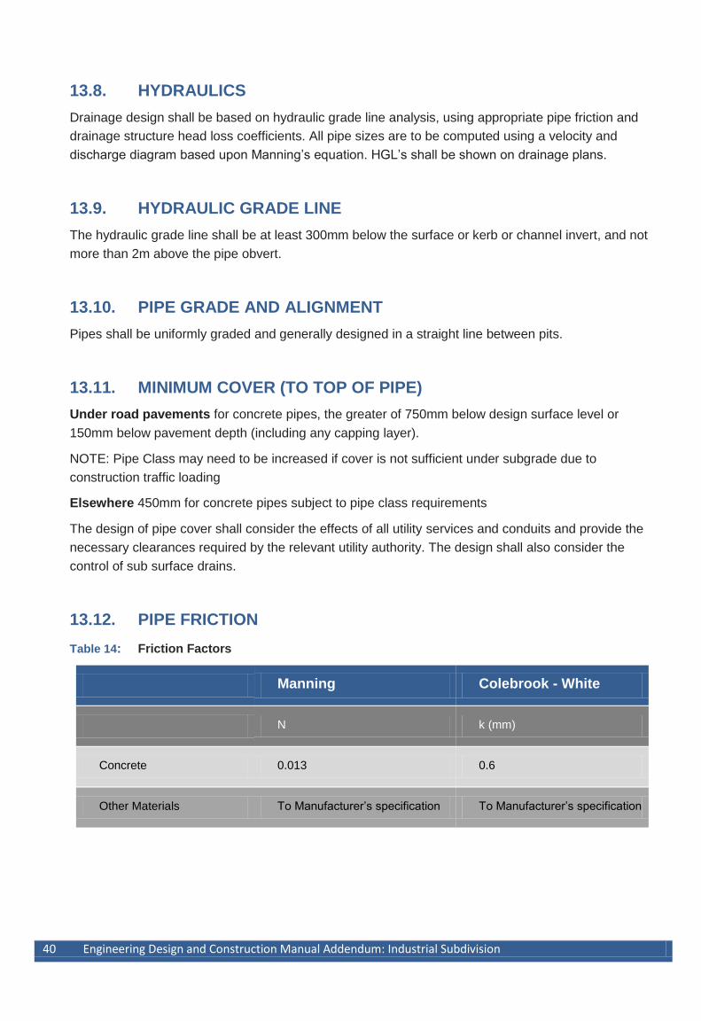
13.12. PIPE FRICTION
Table 14: Friction Factors
Manning Colebrook - White
N k (mm)
Concrete 0.013 0.6
Other Materials To Manufacturer’s specification To Manufacturer’s specification
Engineering design and Construction Manual Addendum: Industrial Subdivision 41
13.13. MINIMUM PIPE SIZE
The minimum pipe size shall be 300mm where road runoff is being collected or the pipe crosses the
road
A reduction in the size of pipes may be permitted for 450mm pipes and above.
13.14. PIPE JOINTS
All pipes shall be rubber ring jointed.
For pipes greater than 900mm and changes in direction between 2 connecting pipes exceeding 10o
construct segmented curves using splayed pipes with bandage joints, having deflections within the
manufacturer’s specification.
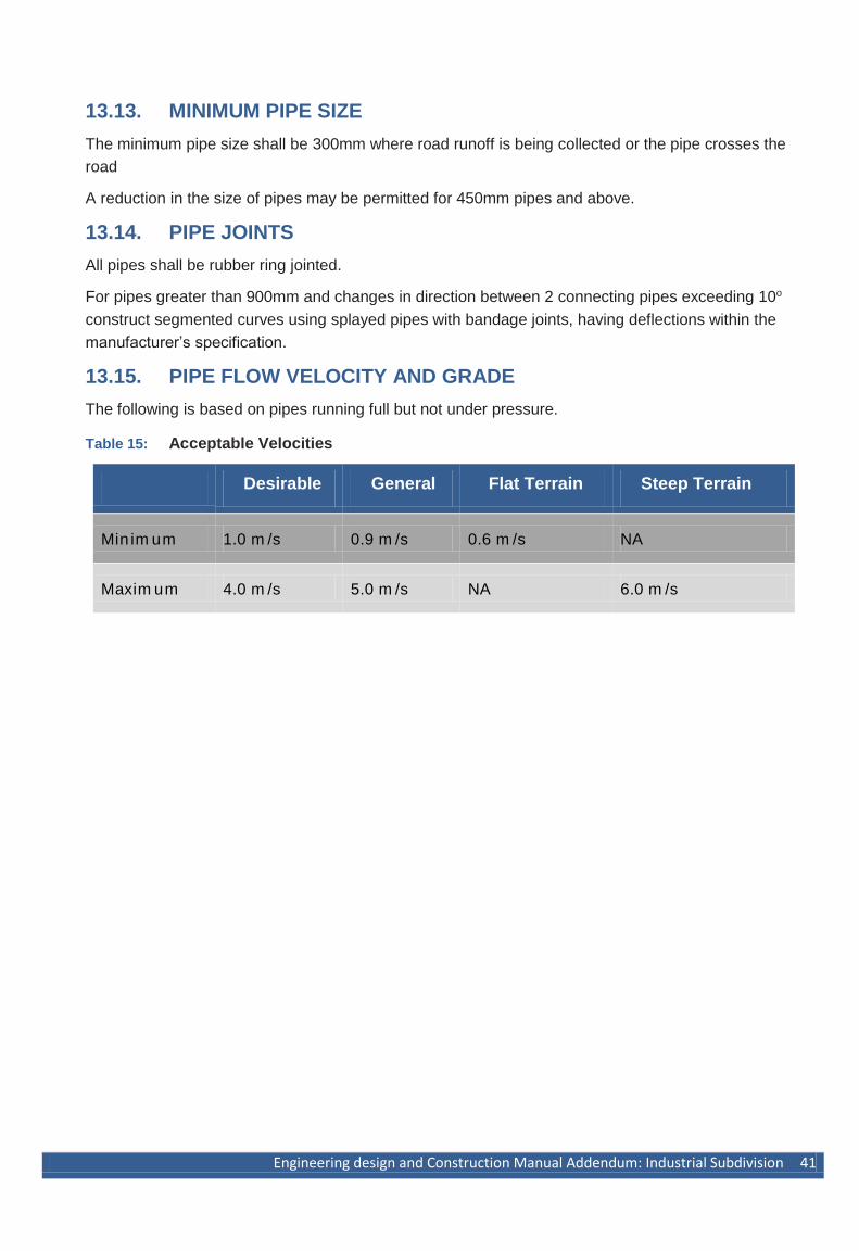
13.15. PIPE FLOW VELOCITY AND GRADE
The following is based on pipes running full but not under pressure.
Table 15: Acceptable Velocities
Desirable General Flat Terrain Steep Terrain
Min im um 1.0 m /s 0.9 m /s 0.6 m /s NA
Maxim um 4.0 m /s 5.0 m /s NA 6.0 m /s
42 Engineering Design and Construction Manual Addendum: Industrial Subdivision
13.16. ANCHOR BLOCKS
Anchor blocks shall be provided where the pipe slope is steeper than 1 in 6 (16%) and the pipe
length is greater than 15m. Refer to the attached standard drawings for details of anchor block
construction.
13.17. ALIGNMENT AT PITS
Where possible, drops and deflections shall be kept to the minimum requirements to maintain the
flow through pits as a jet and minimise head loss created by turbulence.
Required drops (at invert):
Generally 50mm to 100mm for same size pipes.
Match springing lines for change in diameter, but a drop shall not be less than 50mm.
Drops in the range 100mm to 1.5Do are not permitted except:
where springing lines are matched.
for minor branches - (Db < 2/3 DO ) (Db = branch diameter) (D o = outlet diameter)
to dissipate head in steep terrain.
Drops greater than 1.5Do are acceptable on long pipe reaches (where there are considerable
savings in excavation) for pipe sizes up to 450mm.
The maximum permitted deflections in pits are:
D° ≤ 600mm 0° - 50° : align as in standard detail
50°- 90° : provide deflector in pit floor
>90°: not permitted
D° 675mm – 900mm Maximum deflection - 45°
D° ≥ 1050mm Maximum deflection – 10°
Engineering design and Construction Manual Addendum: Industrial Subdivision 43
13.18. PIT LOCATIONS
Pits should, preferably, be located at or about the mid-point of the frontage of allotments, to reduce
the likelihood of conflict with future driveway locations.
Pits shall be located a minimum clearance of 1m from a vehicle crossing.
13.19. KERB INLETS
Pits shall be spaced to capture all surface flow resulting from the design minor rainfall event with a
maximum spacing of 90m.
Kerb inlets are required at the following locations:
Adjacent to tangent points at intersections where the channel falls towards the intersection;
At low points; and
At construction boundaries, unless existing drainage inlets downstream are adequate.
Additional kerb inlets shall be provided at;
Double entry pits at low points of streets where one or both channel grades are greater than
7%.
Flat vertical curves approximately 10m either side of the low point, except where saw tooth
grading of the kerb is employed.
A 50% blockage factor shall be allowed when designing the inlet capacity of grated entry pits at low
points.
13.20. PIT HEAD LOSSES
To be calculated using procedure in the ARR and AustRoads design procedures.
13.21. PROPERTY CONNECTIONS
A property connection shall be placed at the lowest point of each property.
Stormwater outlets for all allotments shall be connected to an underground drain within the road
reserve via a pit.
Whenever depth of a connection is critical for adequate lot control the invert level shall be calculated
and shown on the plans.
44 Engineering Design and Construction Manual Addendum: Industrial Subdivision
13.22. SURFACE DRAINAGE
13.22.1. Flow
The maximum depth of flow in a channel, for a 10% AEP design storm, shall be 0.14m for barrier
type kerb and channel and 0.11m for SM2 roll-over type kerb and channel.
The maximum width of flow in the channel and roadway for a design storm shall not be greater than
3.0m, or the width of a parking lane if one is provided.
In locations where the level at a property line is below the kerb level, care should be taken to ensure
the maximum allowable depth of flow is not exceeded.
Where a low point occurs in a longitudinal road grading or at the end of a court bowl, the footpath or
fixed level at the property line shall be designed to prevent inundation of adjoining lots while
providing for any overland flow path required for the 1% AEP runoff.
13.22.2. Gap Flows
The maximum depth and velocity of flow along an overland flow path for a 1% AEP design storm
shall be in accordance with relevant requirements including the Melbourne Water ‘Land
Development Manual’.
13.22.3. Freeboard
Finished levels of allotments adjacent to overland flow paths for a 1% AEP design storm should
ensure gap flows are retained in the road reserve. The 150mm freeboard (i.e. the level 150mm
above the gap flow level) will be allowed to extend a maximum of 2.0m into the lot.
13.22.4. Overland Flow Paths
Trapped low points in streets and reserves adjacent to private property shall only be permitted where
an overland flow path can be provided for the 1% AEP design storm clear of private property and
unencumbered open space. The use of surface grates and pipes with capacity exceeding the 10%
AEP design shall not be relied upon to avoid the provision of the overland flow path.

Engineering design and Construction Manual Addendum: Industrial Subdivision 45
13.23. WATER QUALITY
Where required, drainage design will incorporate water quality treatment measures to enhance
quality of the drainage runoff before discharging into waterways or other main drainage networks.
Water Sensitive Urban Designs shall be prepared in consultation with Council’s engineering and
planning departments and in accordance with the requirements of Melbourne Waters publication
“WSUD Engineering Procedures”.
13.24. SUB SURFACE DRAINAGE
Sub surface drainage is to be provided as indicated in the attached standard drawings and shall
discharge into pits at a level above the highest obvert of any stormwater pipe open to the pit.
In situations where the swell potential of the sub grade is 2.5% or more (i.e. highly expansive
subgrade), a continuous unbroken capping layer is generally required. In these cases the invert of
the sub surface drain is to be raised such that it drains the pavement only. Trenches for the sub
surface drains must not be below the capping layer into the subgrade.(see also Section 11.9)
Provision should be made for “flush-out-risers” at crests in accordance with standard drawings and
the construction specification.