engineering design of vertical test stand...
TRANSCRIPT

ENGINEERING DESIGN OF VERTICAL TEST STAND CRYOSTAT S. K. Suhane, N.K.Sharma, S.Raghavendra, S.C.Joshi, S.Das, P. K. Kush, V. C. Sahni and
P.D.Gupta, Raja Ramanna Centre for Advanced Technology, Indore, INDIA
C.Sylvester, R.Rabehl, J.Ozelis, C.M.Ginsburg, R.Carcagno and S.Mishra, Fermi National Accelerator Laboratory, Batavia, IL, USA
Abstract
Under Indian Institutions and Fermilab collaboration, Raja Ramanna Centre for Advanced Technology and Fermi National Accelerator Laboratory are jointly developing 2K Vertical Test Stand (VTS) cryostats for testing SCRF cavities at 2K. The VTS cryostat has been designed for a large testing aperture of 86.36 cm for testing of 325 MHz Spoke resonators, 650 MHz and 1.3 GHz multi-cell SCRF cavities for Fermilab’s Project-X. Units will be installed at Fermilab and RRCAT and used to test cavities for Project-X. A VTS cryostat comprises of liquid helium (LHe) vessel with internal magnetic shield, top insert plate equipped with cavity support stand and radiation shield, liquid nitrogen (LN2) shield and vacuum vessel with external magnetic shield. The engineering design and analysis of VTS cryostat has been carried out using ASME B&PV Code and Finite Element Analysis . Design of internal and external magnetic shields was performed to limit the magnetic field inside LHe vessel at the cavity surface <1 µT. Thermal analysis for LN2 shield has been performed to check the effectiveness of LN2 cooling and for compliance with ASME piping code allowable stresses.
INTRODUCTION Vertical cavity test facility (VCTF) is required to
evaluate super conducting radio frequency (SCRF) cavity performance at high fields. A cavity vertical test consists of measurement at 4.5K and 2K, of the quality factor (Qo) as a function of cavity gradient (Eacc). The design of VCTF is based on existing facility VTS-1 in Fermilab, with certain modifications based on operational experience [1]. In this paper we present the VTS cryostat engineering design details. VTS cryostat assembly comprises of vacuum-insulated ASME Code stamped stainless steel pressure vessel suitable for 2.0K helium service, process piping, vacuum vessel manufactured from stainless steel, multilayer super-insulation (MLI), liquid nitrogen cooled thermal shield assembly and piping, internal and external magnetic shields, shipping restraint, control valves, top plate assembly including internal radiation shield, baffles, cavity support plate and instrumentation. 3-D model of top portion of VTS assembly is shown in Fig. 1.
DESIGN CONSIDERATIONS
The VTS Cryostat is required to accommodate 325 MHz single spoke resonators (74.11 cm diameter x 56.77 cm length), triple spoke resonators (109.24 cm diameter x 126.59 cm length), 650 MHz- 5 cell cavities, 1.3 GHz 9-cell (21.18 cm diameter x 122.58 cm length) and single cell (21.18 cm diameter x 122.58 cm length) cavities. The magnetic shielding attenuates the magnetic field at the cavity surface to <1µT at 2K. Internal fixed and external movable radiation shielding ensure that exposure to personnel is maintained below 2.5 µSv/hr in normal working areas. The top plate assembly has provisions for RF cable connections to the cavities, active cavity vacuum pumping and cavity diagnostic instrumentation connections for multiple cavities.
Figure 1: VTS Assembly
MECHANICAL DESIGN
Liquid helium vessel The liquid helium vessel is a thin wall vessel of
92.25 cm inside diameter and 486.03 cm overall length, made of stainless steel grade AISI 304. The internal maximum allowable working pressure (MAWP) of the vessel is 4.5 bar surrounded by vacuum. The vessel has been designed using ASME B&PV Code, section VIII, division 1. Following code calculations, a 13 GA sheet (0.22 cm) is selected for its fabrication. To withstand external pressure of 1 bar, suitable stiffening rings have been designed and provided at a spacing of 38 cm.
Vacuum vessel
Vacuum Vessel
Top Insert Plate
LN2 Shield
Liquid Helium Vessel
FERMILAB-CONF-11-138-TD

Vacuum vessel has been designed to ensure that the ASME Code allowable stresses for the material are not exceeded and to ensure that the vessel is stable (resistant to buckling). It is designed to withstand maximum external pressure of 1 bar and internal pressure of 1 bar. The vacuum vessel is 137.16 cm outer diameter and 541.96 cm overall length. Based on code calculations a design thickness of 3.8 cm is selected, which ensures that the maximum allowable external working pressure is 3.5 times of external design pressure.
Liquid helium vessel flange This flange is part of the helium vessel assembly, in
addition to functioning as a cover for the vacuum vessel. Following the code calculations a thickness of 3.8 cm was selected. The flange has many openings, including a large 92.25 cm diameter opening that is close to, but not at the center. The ASME Code does not have specific rules for an opening of this location. Therefore, a finite element analysis was performed using ANSYS software to verify the flange design. Loads due to external atmospheric pressure and weight of top insert plate, cavity insert, liquid helium vessel, thermal shield, magnetic shield, various piping, etc. were considered in the structural analysis. The analysis indicated a maximum stress of 60.5 MPa (8786 psi) as shown in Fig. 2.
Figure 2: Stress distribution for helium vessel flange
Top insert plate Top insert plate supports the weight of SCRF-
cavities, support and instrumentations. It has been designed using ASME Code for an internal pressure of 4.5 bar and an external pressure of 1 bar. The top insert plate has several reinforced penetrations, hence a finite element analysis was performed using ANSYS software to verify the top insert plate design. The plate of thickness 3.8 cm was modeled using thin shell elements. A structural analysis was carried out to evaluate the stresses and deformations. The analysis results in a maximum stress of 74.2 MPa (10773 psi) at the outer edge of the top insert plate as shown in Fig. 3.
The structural analysis for complete cryostat assembly consisting of top insert plate, helium vessel flange, vacuum vessel flange, liquid helium vessel weld
rim to weld liquid helium vessel, top section of vacuum vessel shell and supports for vacuum vessel flange was performed to evaluate the stresses and deformations in the
Figure 3: Stress distribution for top insert plate
cryostat assembly, supported on 6 equally distributed levelling pads of 2.5 cm diameter. The external pressure on the assembly and weight of all the components were considered for the analysis. The analysis indicates a maximum stress of 99 MPa (14359 psi) at the levelling pads. At other locations in the assembly, the stresses are less than 39.7 MPa (5757 psi) as shown in Fig. 4. The analysis ensures the safe loading of the flanges and structural stability of the assembly during cryostat operation.
Figure 4: Stress distribution for cryostat assembly
THERMAL DESIGN OF LN2 SHIELD The helium vessel and helium piping are thermally
shielded with a LN2 cooled copper shield assembly. The outer diameter of the LN2 shield is 126.36 cm with a wall thickness of 0.31 cm and length of 474.3 cm. The steady state thermal analysis for LN2 shield assembly was performed to check the effectiveness of LN2 cooling. The heat load on thermal shield considering the radiation and heat conduction from the structure is taken as 120 watts. The liquid nitrogen supply in the trace tubing of the LN2 shield is considered at a bulk temperature of 92 K with a flow rate as 3 g/s. The temperature distribution obtained
from the analysis indicates a maximum temperature of 92.7 K in the central region of the LN2 shield as shown in Fig. 5. The analysis suggests that the trace tube layout on LN2 shielding is efficient for providing required cooling.
Figure 5: Steady state temperature distribution for thermal shield
Due to large mass difference between the shell of LN2 shield and trace tubing, it is expected to have a large temperature gradient during the cool down. This may result in large stresses on the tubing and shell joint. A transient thermal analysis was performed to estimate the thermal gradient and stresses developed in the LN2 shield during cool down. It is evaluated from the analysis that the temperature gradient within shell and tube increases initially (Fig. 6), thus creating maximum stresses below 90.3 MPa (13097 psi) when the maximum temperature gradient occurs. Results of analysis are shown in Fig. 7. As per ASME B31.3, the allowable stresses shall not exceed one third of the tensile yield strength of the material (C12200 Temper H80) i.e shall be less than 91.92 MPa (13333 psi).
Figure 6: Temperature variation for thermal shield assembly with time
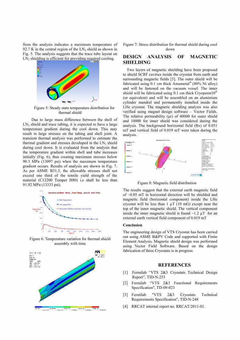
Figure 7: Stress distribution for thermal shield during cool down
DESIGN ANALYSIS OF MAGNETIC SHIELDING
Two layers of magnetic shielding have been proposed to shield SCRF cavities inside the cryostat from earth and surrounding magnetic fields [5]. The outer shield will be fabricated using 0.1 cm thick Amumetal® (80% Ni alloy) and will be fastened on the vacuum vessel. The inner shield will be fabricated using 0.1 cm thick Cryoperm10® (or equivalent) and will be assembled on an aluminium cylinder mandrel and permanently installed inside the LHe cryostat. The magnetic shielding analysis was also verified using magnet design software – Vector Fields. The relative permeability (μr) of 40000 for outer shield and 10000 for inner shield was considered during the analysis. The background horizontal field (Bx) of 0.051 mT and vertical field of 0.019 mT were taken during the analysis.
Figure 8: Magnetic field distribution
The results suggest that the external earth magnetic field of ~0.05 mT in horizontal direction will be shielded and magnetic field (horizontal component) inside the LHe cryostat will be less than 1 µT (10 mG) except near the top of the inner magnetic shield. The vertical component inside the inner magnetic shield is found ~1.2 µT for an external earth vertical field component of 0.019 mT
Conclusion
The engineering design of VTS Cryostat has been carried out using ASME B&PV Code and supported with Finite Element Analysis. Magnetic shield design was performed using Vector Field Software. Based on the design fabrication of three Cryostats is in progress
REFERENCES
[1] Fermilab “VTS 2&3 Cryostats Technical Design Report”, TID-N-253
[2] Fermilab “VTS 2&3 Functional Requirements Specification", TD-09-023
[3] Fermilab "VTS 2&3 Cryostats Technical Requirements Specification", TID-N-248
[4] RRCAT internal report no. RRCAT/2011-01.

[5] Camille M. Ginsburg, Clark Reid, and Dmitri A. Sergatskov, “Magnetic Shielding for the Fermilab Vertical Cavity Test Facility”, FERMILAB-CONF-08-348-TD