engineering economy 14th ed
DESCRIPTION
Engineering EconomyTRANSCRIPT
ii
EXPERIMENTAL STUDY OF RAPID PROTOTYPING OF MANUFACTURINGPLASTIC PRODUCT USING RESPONSE SURFACE METHODOLOGY
SYED MOHD NOR IRSYAD B SAYED MOHD NORDIN
Report submitted in fulfilment of the requirementsfor the award of the degree of
Bachelor of Manufacturing Engineering
FACULTY OF MANUFACTURING ENGINEERINGUNIVERSITI MALAYSIA PAHANG
JUNE 2013

vii
ABSTRACT
This study basically shows a detailed study to manufacture Coffee Maker using
Rapid prototyping using Response Surface Methodology.Fused deposition modeling
(FDM) is a process for developing Rapid Prototyping (RP) objects by depositing
fused layers of material according to numerically defined cross sectional geometry.
The quality of FDM produced parts is significantly affected by various parameters
used in the process. This dissertation work aims to study the effect of three process
parameters such as layer thickness, build orientation, and air gap on mechanical
property of FDM processed parts. In order to reduce experimental runs, Response
Surface Methodology (RSM) based on central composite design (CCD) is adopted.
Specimens are prepared for tensile and surface roughness test as per ASTM
standards. Empirical relations among responses and process parameters are
determined and their validity is proved using analysis of variance (ANOVA).
Response surface plots are analyzed to establish main factor effects and their
interaction on responses. Optimal factor settings for maximization of each response
have been determined. Major reason for weak strength of FDM processed parts may
be attributed to distortion within the layer or between the layers while building the
parts due to temperature gradient. To this end, mechanical properties like tensile
strength and surface roughness finish of the produced parts are considered as
multiple responses and simultaneous optimization has been carried out with the help
of response optimizer. Coffee Maker parts are manufacture using optimum parameter
determines. The Coffee Maker then been assemble and test its function ability.

viii
ABSTRACT
Kajian inipada asasnyamenunjukkankajian terperinciuntuk menghasilkan Coffee
Maker menggunakan Rapid Proto typing menggunakan Response Surface
Methodology. Fused Deposition Modelling (FDM) merupakansalah satu proses
Rapid Prototyping (RP) untuk menghasilkan produk dengan mendepositkan bahan
satu per satu mengikut kerangka yang ditakrifkan mengikut geometri keratan rentas.
Kualiti produk FDM yang dihasilkan dipengaruhi oleh pelbagai parameter yang
digunakan dalam proses tersebut. Kajian tesis ini bertujuan untuk mengkaji kesan
tiga parameter proses seperti ketebalan lapisan, orientasi produk, dan ruang udara ke
atas sifat mekanikal produk yg dihasilkan dari FDM. Dalam usaha untuk
mengurangkan jumlah eksperimen, Response Surface Methodology (RSM) yang
berasakan Central Composite Design (CCD) digunakan. Spesimen disediakan untuk
ujian tegangan dan kekasaran permukaan mengikut piawaian ASTM. Hubungan
empirikal antara tindak balas dan parameter proses ditentukan dan kesahihan mereka
dibuktikan dengan menggunakan analisisvarian (ANOVA). Plot Response Surface
dianalisis untuk mewujudkan kesan faktor utama dan interaksi faktor lain terhadap
tindak balas. Faktor optimum ditetapkan untuk memaksimumkan setiap tindak balas.
Sebab utama kelemahan produk dihasilkan FDM adalah kerana gangguan dalam
lapisan atau di antara lapisan ketika produk dihasilkan kerana suhu yang menurun.
Untuk tujuan ini, sifat-sifat mekanikal seperti kekuatan tegangan dan kekasaran
permukaan bahagian produk yang dikeluarkan dianggap sebagai pelbagai tindak
balas dan pengoptimuman serentak telah dijalankan dengan bantuan pengoptimasi
tindak balas. Bahagian Coffee Maker dihasilkan menggunakan optimum parameter
yang telah ditentukan. Coffee Maker seterusnya dipasang untuk menguji sama ada
Coffee Maker berfungsi atau tidak.
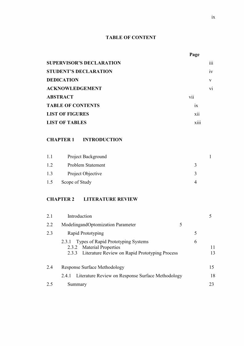
ix
TABLE OF CONTENT
Page
SUPERVISOR’S DECLARATION iii
STUDENT’S DECLARATION iv
DEDICATION v
ACKNOWLEDGEMENT vi
ABSTRACT vii
TABLE OF CONTENTS ix
LIST OF FIGURES xii
LIST OF TABLES xiii
CHAPTER 1 INTRODUCTION
1.1 Project Background 1
1.2 Problem Statement 3
1.3 Project Objective 3
1.5 Scope of Study 4
CHAPTER 2 LITERATURE REVIEW
2.1 Introduction 5
2.2 ModelingandOptomization Parameter 5
2.3 Rapid Prototyping 5
2.3.1 Types of Rapid Prototyping Systems 62.3.2 Material Properties 112.3.3 Literature Review on Rapid Prototyping Process 13
2.4 Response Surface Methodology 15
2.4.1 Literature Review on Response Surface Methodology 18
2.5 Summary 23

x
CHAPTER 3 METHODOLOGY
3.1 Introduction 24
3.2 Process of Rapid Prototyping 24
3.3 Response Surface Methodology and Robust Design 28
3.4 The Sequential Of Response Surface Methodology 28
3.5 Variable Selection and Model Building in Regression 29
3.5.1 Stepwise Regression Methods 30
3.6 Design of Experiment 30
3.6.1 Rapid Prototyping 303.6.2 Response Surface Methodology 323.6.3 Testing Methods 33
3.7 Summary 34
CHAPTER 4 RESULT AND DISCUSSION
4.1 Introduction 35
4.2 Specimen Preparation 35
4.3 Testing of Specimens 36
4.3.1 Testing Specimen for Tensile Test 364.3.2 Testing Specimen for Surface Roughness Test 39
4.4 Analysis of Experiment 41
4.4.1 Analysis for Tensile Test 414.4.2 Analysis for Surface Roughness 44
4.5Discussions 47
4.6 Coffee Maker Part Manufacturing and Assembly 48
4.7 Assembly Time Analysis 52
4.8 Summary 52
CHAPTER 5 CONCLUSION AND RECOMMENDATION
5.1 Conclusion 53
5.2 Limitations and Recommendation 54

xi
REFERENCE 56
APPENDICES
A1 Final Year Project 1 Gant Chart 58
A2 Final Year Project 2 Gant Chart 60
B Specimen Specifications 62
C DFA Analysis Total for Proposed Design 64

xii
LIST OF FIGURES
Figure No: Title Page
Figure 1.1 Three stage of intriguing in rapid manufacturing 2
Figure 2.1 Schematic of Stereolithography Technique 7
Figure 2.2 Schematic of Fused Deposition Modeling Technique 8
Figure 2.3 Schematic of Selective Laser Sintering Technique 9
Figure 2.4 Schematic of Laminated Object Manufacturing 10
Figure 2.5 Schematic of Three Dimensional Printing 11
Figure 2.6 Variation of Surface Roughness with Layer Thickness for
20 Deg Build Orientation 14
Figure 2.7 Variation of Surface Roughness with Layer Thickness for
70 Deg Build Orientation14
Figure 2.8 Cause and effect diagram shown in fishbone diagram 20
Figure 3.1 Flow chart of rapid prototyping 26
Figure 3.2 Coffee maker to be manufacture 26
Figure 3.3 Flow chart for manufacturing of coffee maker parts 34
Figure 4.1 Line diagram of specimen for tensile test and surface
roughness test 36
Figure 4.2 Tensile test 37
Figure 4.3 Specimen before fracture 37
Figure 4.4 Specimen after fracture 37
Figure 4.5 Optical video measuring system used to capture image of surface 39
Figure 4.6 Surfcom 130A used to measure surface 39
Figure 4.7 High surface roughness samples 40
Figure 4.8 Moderate surface roughness samples 40
Figure 4.9 Good surface roughness samples 40
Figure 4.10 Graph of tensile test result for predicted and actual 43
Figure 4.11 Graph of surface roughnessresult for predicted and actual 46
Figure 4.12 Graph of Tensile test and surface roughness 47
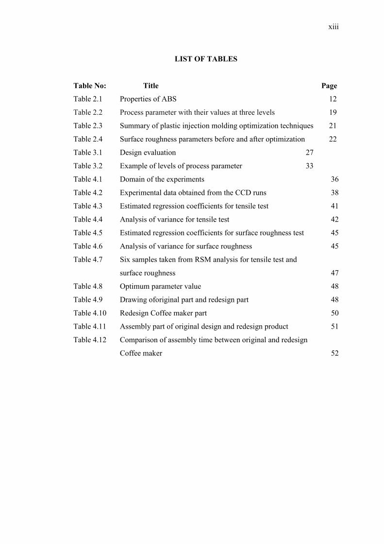
xiii
LIST OF TABLES
Table No: Title Page
Table 2.1 Properties of ABS 12
Table 2.2 Process parameter with their values at three levels 19
Table 2.3 Summary of plastic injection molding optimization techniques 21
Table 2.4 Surface roughness parameters before and after optimization 22
Table 3.1 Design evaluation 27
Table 3.2 Example of levels of process parameter 33
Table 4.1 Domain of the experiments 36
Table 4.2 Experimental data obtained from the CCD runs 38
Table 4.3 Estimated regression coefficients for tensile test 41
Table 4.4 Analysis of variance for tensile test 42
Table 4.5 Estimated regression coefficients for surface roughness test 45
Table 4.6 Analysis of variance for surface roughness 45
Table 4.7 Six samples taken from RSM analysis for tensile test and
surface roughness 47
Table 4.8 Optimum parameter value 48
Table 4.9 Drawing oforiginal part and redesign part 48
Table 4.10 Redesign Coffee maker part 50
Table 4.11 Assembly part of original design and redesign product 51
Table 4.12 Comparison of assembly time between original and redesign
Coffee maker 52
CHAPTER 1
INTRODUCTION
1.1 PROJECT BACKGROUND
In recent years, opening up local market for worldwide competition has led to a
fundamental change in new product development (NPD). In order to stay competitive,
manufactures should be able to attain and sustain themselves as “World Class
Manufactures“. The manufactures should be capable in delivering products in fulfilling
the total satisfaction of customers, product in high quality, short delivery time, at
reasonable cost, environmental concern and fulfill all safety requirements.
In many fields, there is great uncertainty as to whether a new design will actually
do what is desired. New design often have unexpected problems. A prototype is often
used as part of the product design process to allow engineers and designers the ability to
explore design alternatives, test theory and confirm performance prior to starting
production of new products.
Manufacturing cost is something that manufactures most concern about. In order
to reduce producing product cost. It starts from the beginning of process until finishing
process. Waste the money on maintenance is something costly. Rather than that, they
have preferred to put the cost from the start of manufacturing process so that there is no
product defect in future. Parameter control would be a significant role to reduce plastic
product defect in every production.
2
In rapid manufacturing process, methodically designed to provide a mass-
customized product to achieve a desired balance among cost, throughput, and quality is a
mass challenge for engineers and designers.
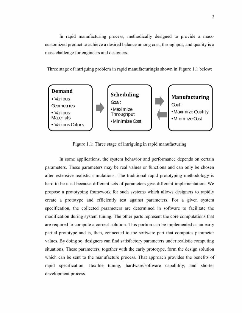
Three stage of intriguing problem in rapid manufacturingis shown in Figure 1.1 below:
Figure 1.1: Three stage of intriguing in rapid manufacturing
In some applications, the system behavior and performance depends on certain
parameters. These parameters may be real values or functions and can only be chosen
after extensive realistic simulations. The traditional rapid prototyping methodology is
hard to be used because different sets of parameters give different implementations.We
propose a prototyping framework for such systems which allows designers to rapidly
create a prototype and efficiently test against parameters. For a given system
specification, the collected parameters are determined in software to facilitate the
modification during system tuning. The other parts represent the core computations that
are required to compute a correct solution. This portion can be implemented as an early
partial prototype and is, then, connected to the software part that computes parameter
values. By doing so, designers can find satisfactory parameters under realistic computing
situations. These parameters, together with the early prototype, form the design solution
which can be sent to the manufacture process. That approach provides the benefits of
rapid specification, flexible tuning, hardware/software capability, and shorter
development process.
Demand• VariousGeometries• VariousMaterials• Various Colors
SchedulingGoal:•MaximizeThroughput•Minimize CostManufacturingGoal:•Maximize Quality•Minimize Cost
3
Since the introduction of rapid prototyping technology as a tool for time
compression and concurrent engineering in the design and manufacturing process, many
enhancements and refinements have been made based on the experience of users and
manufacturers of rapid prototyping equipment. These improvements contribute
significantly to better production of quality output from rapid prototyping systems. This
project reviews the role of several of these parameters in the process.
1.2 PROBLEM STATEMENT
Rapid Prototyping (RP) or Layer Manufacturing (LM) refers to fabrication of
layer-by-layer. Additional layer or fewer layers will affect to plastic product defect.
Mostly, plastic product defect happened during process time. Plastic product defect play
a significant role in increasing production cost. Therefore, parameter control during RP
process is compulsory in order to reduce plastic product defect. This study will focus on
modeling and optimization suitable parameter of RP of plastic product manufacturing
using Response Surface Methodology (RSM).
1.3 PROJECT OBJECTIVES
Basically, this study required the student to apply the concept of compulsory and
cost reduction in producing plastic product. The study is on manufacturing of coffee
maker using rapid prototyping (RP) using response surface methodology (RSM).
Material use in manufacturing coffee maker is ABS. Objective of this projectis:
i. To analyze parameter effect to manufacturing of coffee maker such as, build
orientation, layer thickness, and air gap.
ii. To implement Response Surface Methodology (RSM) in RP process for
producing coffee maker parts.
iii. To testtensile strength, surface roughness finish, function ability and accuracy to
assemble the coffee maker parts.

4
1.4 SCOPE OF STUDY
This project require proper plan in order to achieve the project objective. There is
some scope of study:
i. Initial study about Rapid Prototyping process
ii. Study on importance of parameter in manufacturing process
iii. Initial study and implementing Response Surface Methodology on RP process
iv. Manufacture of Coffee Maker Machine using Rapid Prototyping
v. Assemble coffee maker part accuracy, tensile test, surface roughness finish and
function ability of coffee maker
Gantt chart for project schedule is attached in Appendix A.

CHAPTER 2
LITERATURE REVIEW
2.1 INTRODUCTION
A rational method to fabricate coffee maker and easy to assembly the part is the
most important selection for producing these products. Basically 20 to 30 percent
defects of product occur during manufacturing process. So, a design engineer should be
concerned with the defects that cost manufacturing process. Thus, concept of response
surface methodology (RSM) applied on rapid prototyping (RP).
2.2 MODELING AND OPTOMIZATION PARAMETER
In general, parameter is used to identify a characteristic, a feature, a measurable
factor that can help in defining a particular system. A Parameter is an important element
to take into consideration for the evaluation or for the comprehension of an event, a
project or any situation.Parameters are dimensionless, or have the dimension of time or
its reciprocal. In order to modeling and optimize suitable, industrial engineer should take
many factors when deciding the applicability of product design, including quality of
product, rational use of parameter, applicability of manufacturing process and so on.
2.3 RAPID PROTOTYPING
RP is a generic term for a number of technologies that enable components to be
made without the need for conventional tooling in the first instance or indeed without

6
the need to engage the services of skilled model-makers. Many manufacturing processes
are subtractive, in that they modify the geometry of a mass of material by removing
parts of the material until the final shape is achieved. Conventional milling and turning
are good examples of subtractive processes. By contrast, RP techniques are additive
processes. RP components are built-up gradually in layers until the final geometry is
obtained. The way in which the layers are produced, however, and the materials in
which parts can be built vary significantly between the different RP processes.
The starting point for the RP process is typically a 3D CAD model prepared and
exported to meet the requirements of a given technology. Various other “inputs”, in
addition to CAD, can be used to create RP components; these include medical
applications such as MRI and CAT scanning as well as point cloud data generated by
engineering scanning or digitising systems. Whatever be the source of the original data it
is reformatted into anstl file and sliced horizontally, each individual slice is subsequently
presented to the selected RP manufacturing process. The RP system will subsequently
reproduce the sliced data thereby creating a physical example of the original “CAD”
data.
Each RP technique has its own advantages and disadvantages. These must be
understood thoroughly before an RP process is selected; otherwise, a part that does not
completely fulfill the requirements of the end-user may be produced, and
disappointment in the use of RP technology is likely to occur.
2.3.1 Types of Rapid Prototyping Systems
Various types of Rapid Prototyping systems had been developed, in order to
coordinate with the highly demands of new products from the market. The most
common types of RP systems that available in the market are Stereolithography (SLA),
Fused Deposition Modeling (FDM), Selective Laser Sintering (SLS), Laminated Object
Manufacturing (LOM), and Three Dimensional Printing (3D printing). In this study,
FDM is used. Different types of machines have their strength and weakness in producing
7
the products. Below are shown the details of operation principle for five common types
of RP systems.
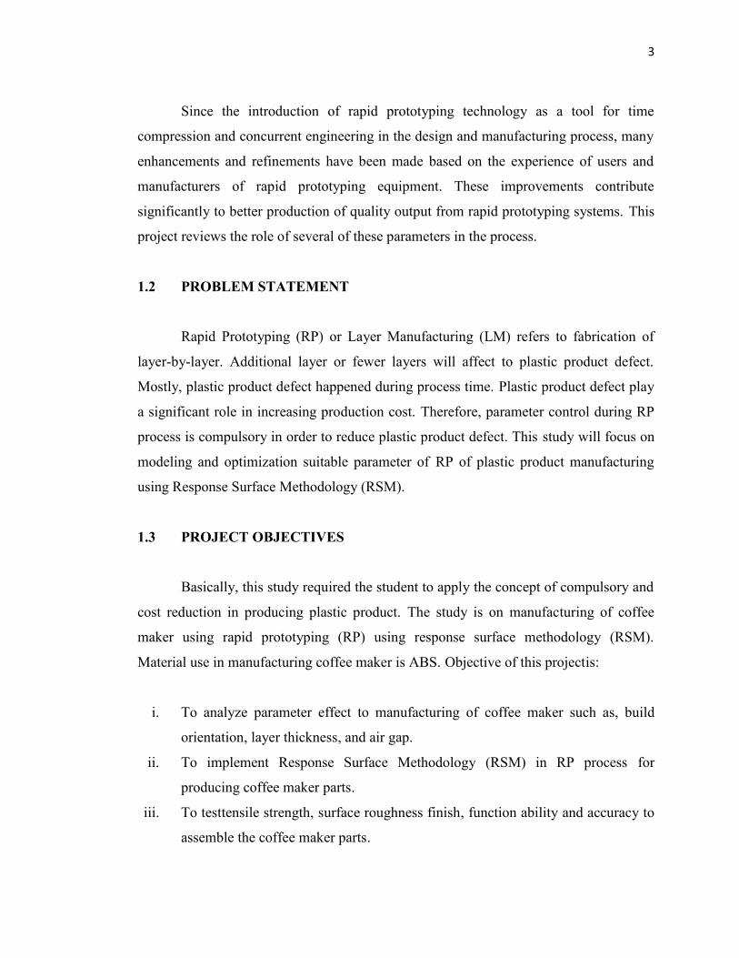
Figure 2.1 shows that the stereolithography technique. The building process
begins with the vat filled with the photopolymer liquid and the elevator table set just
below the surface of the liquid. Then the mirror is directed to focus the laser beams so
that it solidifies a two dimensional cross section on the surface of the photopolymer. The
elevator table then drops enough to cover the solid polymer with another layer of the
liquid, which is solidified by laser. This process continues, building the part from the
bottom up, until the system completes the product. The part is then raised out of the vat
and removal of excess polymer begins by wicking, which uses a blotting material to
absorb uncured polymer, immersion in an alcohol bath, or ultrasonic cleaning. It then
proceeds to the Post Curing Apparatus (PCA) for the final cure.
Figure 2.1: Schematic of Stereolithography Technique.
(Source: http://cgm.cs.mcgill.ca/~godfried/clipart/stereolithography)
Next technique is Fused Deposition Modeling. The plastic filament is wounded
in the material spool and supplied directly into the heated extrusion head, where the
material is melted. The molten material will be extruded from the extrusion nozzle. The
nozzle is mounted on a mechanical stage which allows the nozzle move in axis X and
axis Y. Then nozzle will be move according to drawing in STL format, and will deposit

8
the thin bead of molten plastic based on the required geometry layer by layer. The
molten plastic will solidified immediately after squeezed out from the nozzle and
directly bond with the layer below. The whole operation process is held in an oven
chamber with the melting temperatures just below the melting point of the materials.
This technique requires small amount of additional thermal energy to melt the material.
For any model that design have overhanging geometry, support structure need to be
create before start the fabrication processes and the support will be remove in the post
processing stage. Types of materials available for this RP system are Acrylo-nitrile
Butadiene Styrene (ABS), elastomer, polycarbonate, wax, and polysulphones. The
implementation of Fused Deposition Modeling (FDM) technique is shown in Figure 2.2.
Figure 2.2: Schematic of Fused Deposition Modeling Technique.
(Source: http://www.maxfac.com)
Third technique in this RP is Selective Laser Sintering. This RP technique begins
with the building process with a thin layer of powder first deposited in the part build
envelope. While the process is carried out, the piston of the powder feed cartridge will
move up in order to supply the powder. However, laser beam is guided by a process-
control computer using instruction generated by the 3D CAD program of the desired
part; is then focused on that layer, tracing and sintering a particular cross section into a

9
solid mass. The roller will spread the powder into the part of build envelope in order to
build-up the first layer according to the cross section had been traced by the laser beam.
The powder in others area must remain loose, in order to support the sintered part.
Another layer of powder is now deposited; this cycle is repeated again and again until
the entire three-dimensional part is produced. The loose particles are then shaken off,
and the part is removed. The part produced from this technique does not require the
further curing, excepted ceramic. The implementation of SLS is shown in Figure 2.3.
Figure 2.3: Schematic of Selective Laser Sintering Technique
(Source:http://www.azom.com/details.asp?ArticleID=1648)
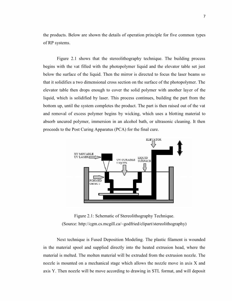
As shown in Figure 2.4, Laminated Object Manufacturing technique begins with the
material is fed onto the material supply roll and is heated by the laminating roller in
order to bond the material on the previous material. The laminating roller melts the
plastic coating on the bottom side of the paper to create the bond. The profile of the
model is traced out by the optic systems, which consist from laser and optics that
mounted on the X-Y positioning stage. This process will generate smokes so the
chamber needs to seal during the building process carries out. After completed the
cutting process, the extra paper will be wound on the take up roll. This method also not
10
required to create the support structure before the fabrication because extra papers
become the support structure during the building process. Areas of cross sections which
are to be removed in the final model are heavily cross-hatched with the laser to facilitate
removal. It’s take quite long time of the removal process for certain geometry of models.
Figure 2.4: Schematic of Laminated Object Manufacturing
(Source: AshutoshChouksey, 2012)
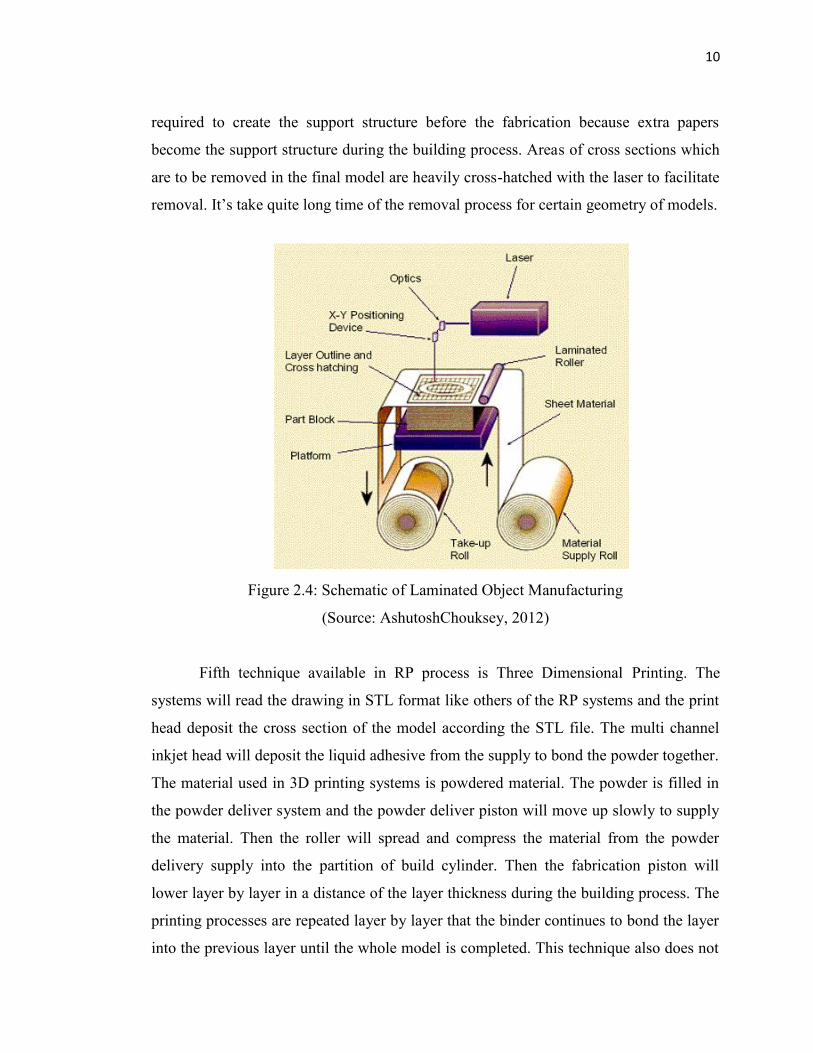
Fifth technique available in RP process is Three Dimensional Printing. The
systems will read the drawing in STL format like others of the RP systems and the print
head deposit the cross section of the model according the STL file. The multi channel
inkjet head will deposit the liquid adhesive from the supply to bond the powder together.
The material used in 3D printing systems is powdered material. The powder is filled in
the powder deliver system and the powder deliver piston will move up slowly to supply
the material. Then the roller will spread and compress the material from the powder
delivery supply into the partition of build cylinder. Then the fabrication piston will
lower layer by layer in a distance of the layer thickness during the building process. The
printing processes are repeated layer by layer that the binder continues to bond the layer
into the previous layer until the whole model is completed. This technique also does not

11
need create any support structure before the fabrication process; this is because, just like
the Selective Laser Sintering technique, the excess powdered material will support the
model until the model is completed. In order to achieve the desired hardness in order to
prevent any damage before handling, the model needs be infiltrated with a hardener. The
implementation of 3D Printing is shown in Figure 2.5.
Figure 2.5: Schematic of Three Dimensional Printing
(Source: http:home.att.net/~castleisland/)
2.3.2 Material and Properties
Acrylonitrile Butadiene Styrene (ABS) chemical formula (C8H8· C4H6·C3H3N)n) is a
common thermoplastic used to make light, rigid, molded products such as piping (for
example Plastic Pressure Pipe Systems), musical instruments (most notably recorders and
plastic clarinets), golf club heads (used for its good shock absorbance), automotive body
parts, wheel covers, enclosures, protective head gear, buffer edging for furniture and joinery
panels, airsoft BBs and toys, including Lego bricks. ABS plastic ground down to an average
diameter of less than 1 micrometer is used as the colorant in some tattoo inks. Tattoo inks
that use ABS are extremely vivid. This vividness is the most obvious indicator that the ink
contains ABS, as tattoo inks rarely list their ingredients.
12
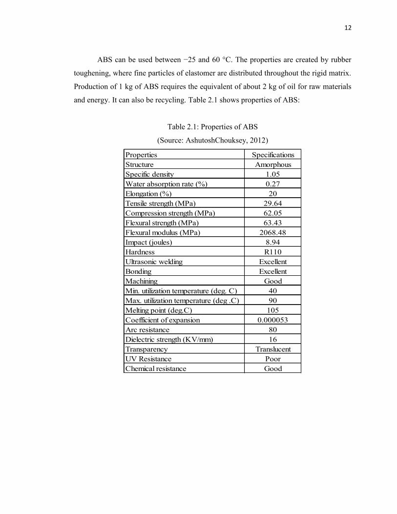
ABS can be used between −25 and 60 °C. The properties are created by rubber
toughening, where fine particles of elastomer are distributed throughout the rigid matrix.
Production of 1 kg of ABS requires the equivalent of about 2 kg of oil for raw materials
and energy. It can also be recycling. Table 2.1 shows properties of ABS:
Table 2.1: Properties of ABS
(Source: AshutoshChouksey, 2012)
Properties SpecificationsStructure AmorphousSpecific density 1.05Water absorption rate (%) 0.27Elongation (%) 20Tensile strength (MPa) 29.64Compression strength (MPa) 62.05Flexural strength (MPa) 63.43Flexural modulus (MPa) 2068.48Impact (joules) 8.94Hardness R110Ultrasonic welding ExcellentBonding ExcellentMachining GoodMin. utilization temperature (deg. C) 40Max. utilization temperature (deg .C) 90Melting point (deg.C) 105Coefficient of expansion 0.000053Arc resistance 80Dielectric strength (KV/mm) 16Transparency TranslucentUV Resistance PoorChemical resistance Good

13
2.3.3 Literature Study on Rapid Prototyping Process
First literature study is from journal written by Ahn Sung Hoon, at all (2002).
This research is focused on raster orientation and air gap parameter. This research uses
design of experiment method and concluded that the air gap and raster orientation affect
the tensile strength of FDM processes. They further compare the measured tensile
strength of FDM part processed at different raster angles and air gap with the tensile
strength of injection moulded part. Material use for both type of fabrication is ABSP400.
With zero air gap FDM specimen tensile strength lies between 10%-73% of injection
moulded part with maximum at 0° and minimum at 90° raster orientation with respect to
loading direction. But with negative air gap there is significant increase in strength at
respective raster orientation. All specimens failed in transverse direction except for
specimen whose alternate layer raster angle varies between 45° and -45°. This type of
specimen failed along the 45° line. Compression test on the specimen build at two
different orientations revealed that this strength is higher than the tensile strength and
lies between 80 to 90% of those for injection moulded part.
Second literature study is from journal written by P. Vijay at all (2011). In the
study, surface finish is critical as it can affect the part accuracy, reduce the post-
processing costs and improve the functionality of the parts. This paper presents an
experimental design technique for determining the optimal surface finish of a part built
by varying build orientation, layer thickness. The procedure for the analysis of the
surface roughness response in this research was performed as follows:
The response variable was chosen.
The effects were calculated.
Significant effects were chosen from the graph.
The model graphs were analyzed.
14
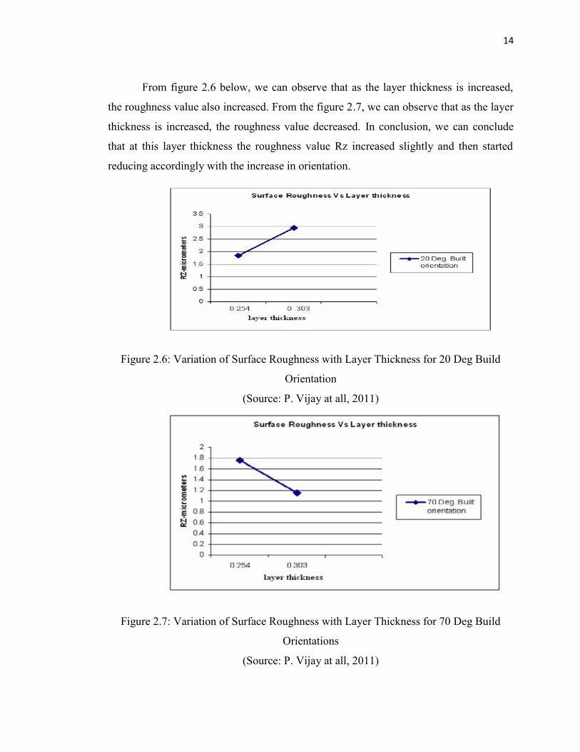
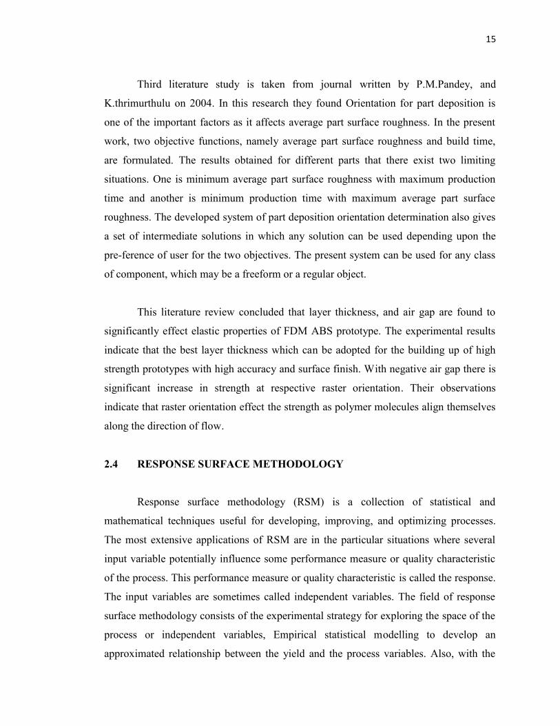
From figure 2.6 below, we can observe that as the layer thickness is increased,
the roughness value also increased. From the figure 2.7, we can observe that as the layer
thickness is increased, the roughness value decreased. In conclusion, we can conclude
that at this layer thickness the roughness value Rz increased slightly and then started
reducing accordingly with the increase in orientation.
Figure 2.6: Variation of Surface Roughness with Layer Thickness for 20 Deg Build
Orientation
(Source: P. Vijay at all, 2011)
Figure 2.7: Variation of Surface Roughness with Layer Thickness for 70 Deg Build
Orientations
(Source: P. Vijay at all, 2011)
15
Third literature study is taken from journal written by P.M.Pandey, and
K.thrimurthulu on 2004. In this research they found Orientation for part deposition is
one of the important factors as it affects average part surface roughness. In the present
work, two objective functions, namely average part surface roughness and build time,
are formulated. The results obtained for different parts that there exist two limiting
situations. One is minimum average part surface roughness with maximum production
time and another is minimum production time with maximum average part surface
roughness. The developed system of part deposition orientation determination also gives
a set of intermediate solutions in which any solution can be used depending upon the
pre-ference of user for the two objectives. The present system can be used for any class
of component, which may be a freeform or a regular object.
This literature review concluded that layer thickness, and air gap are found to
significantly effect elastic properties of FDM ABS prototype. The experimental results
indicate that the best layer thickness which can be adopted for the building up of high
strength prototypes with high accuracy and surface finish. With negative air gap there is
significant increase in strength at respective raster orientation. Their observations
indicate that raster orientation effect the strength as polymer molecules align themselves
along the direction of flow.
2.4 RESPONSE SURFACE METHODOLOGY
Response surface methodology (RSM) is a collection of statistical and
mathematical techniques useful for developing, improving, and optimizing processes.
The most extensive applications of RSM are in the particular situations where several
input variable potentially influence some performance measure or quality characteristic
of the process. This performance measure or quality characteristic is called the response.
The input variables are sometimes called independent variables. The field of response
surface methodology consists of the experimental strategy for exploring the space of the
process or independent variables, Empirical statistical modelling to develop an
approximated relationship between the yield and the process variables. Also, with the
16
help of response surface methodology, optimization can be done for finding the values
of the process variables that produce desirable values of the response.In general, the
relationship between the response y and independent variables , , … , is,
= ( , , … , ) + (2.1)Where includes effects such as measurement error on the response, background
noise, the effect of other variables, and so on. Usually ε is treated as a statistical error,
often assuming it to have a normal distribution with mean zero and variance σ2. Then,
Ε( ) = = Ε[ ( , , … , )] + Ε( ) = ( , , … , ) (2.2)The variables , , … , in equation (4.2) are usually called the natural
variables, because they are expressed in the natural units of measurement, such as
degrees Celsius, pounds per square inch, etc. In much RSM work, it is convenient to
transform the natural variables to coded variables , , … , , which are usually
defined to be dimensionless with mean zero and the same standard deviation. In terms of
the coded variables, the response function equation (2.2) can be written as,
= ( , , … , ) (2.3)
Because the form of the true response function is unknown, it should be
approximated. In fact, successful use of RSM is critically dependent upon the
experimenter’s ability to develop a suitable approximation. Usually, a low-order
polynomial in some relatively small region of the independent variable space is
appropriate. In many cases, either a first-order or a second-order model is used. The
first-order model is likely to be appropriate when the experimenter is interested in
approximating the true response surface over a relatively small region of the
independent variable space in a location where there is little curvature in response