engineering mechanics - diplomadiploma.vidyalankar.org/wp-content/uploads/mech_soln… · ·...
TRANSCRIPT

1
F.Y. Diploma : Sem. II [AE/CE/CH/CR/CS/CV/EE/EP/FE/ME/MH/MI/PG/PT/PS]
Engineering Mechanics Time : 3 Hrs.] Prelim Question Paper Solution [Marks : 100
Q.1 Attempt any TEN of the following : [20]Q.1(a) Difference between mass and weight? [2](A) Difference between mass and weight
Mass Weight 1. Mass is the quantity of matter
contained in a body. Weight of a body is the force with which the body is attracted by the earth towards its centre.
2. It is scalar quantity. it is a vector quantity. 3. S.I. unit of mass is ‘ky’ S.I. hit of weight is ‘N’.
Q.1(b) State Newton’s Laws of motion? (First, Second & Third) [2](A) Nowtons first law : “ Everybody continues to be in its state of rest or of uniform motion in
a straight line, unless it is acted upon by some external agency”. Second Law : “The rate of change of momentum is directly proportional to applied forces”. Third Law : To every action there is equal and opposite reaction.
Q.1(c) Define Resolution of force. [2](A) Resolution of force :
The way of representing a single force into number of forces without changing the effect of force on body is called resolution of force.
Q.1(d) Define effort and effort lost in friction. [2](A) Effort(P) : The force applied to lift the heavy loads is known as effort. Effort lost in friction (Pf): It is the effort by considering the wear and tear effect while
use of machine. OR
It is the effort obtained by subtracting ideal effort from an effort. Q.1(e) What is polar diagram? [2](A) Polar Diagram : In case of non-concurrent or parallel force system the point of
application of resultant can be found out by constructing polar diagram. Polar diagram is obtained from the vector diagram. To construct a polar diagram, any point “O” known as pole is chosen near the vector diagram and the points on the vector diagram are joined to it. The lines joined in this way are known as rays.

Vidyalankar : F.Y. Diploma Engineering Mechanics
2
Q.1(f) State types of friction. [2](A) (i) Static friction : The friction experienced by a body when it is in equilibrium. (ii) Dynamic friction : The friction experienced by a body when it is in motion. (iii) Rolling : The friction experienced by a bodies when one rolls over the another body. (iv) Sliding : The friction experienced by a bodies when one slides over the another body. Q.1(g) State principle of transmissibility of force. [2](A) Principle of transmissibility of force : If force acts at a point on a rigid body, it is assumed to act at any other point on line of
action of force within the body. Q.1(h) What is Bow's notation ? Explain with a sketch. [2](A) Bow’s notation Bow’s notation is used designate a force as per this notation, each force
is designated or named by two spaces one on each side of the line of action of a force. This space are generally named by capital letter’s as A, B, C serially.
Explanation
A force say ‘F’ acting on rigid body divided space above or below it into two parts, say A and B hence the force ‘F’ is named as AB.
Q.1(i) Explain meaning of self locking machine. State the condition for it. [2](A) SelfLocking Machine A machine which is not capable of doing work in reverse direction even on removal of effort,
then the machine is called as selflocking or Nonreversible machine. Condition for SelfLocking Machine Efficiency < 50 % < 50 % Q.1(j) State velocity ratio for screw jack with meaning of term involved. [2](A) Velocity Ratio of Simple Screw jack is given by VR = 2L / P When handle of length L is provided
OR VR = 2R / P When effort wheel is provided Where, L = length of handle P = pitch of screw R = radius of an effort wheel. Q.1(k) What is coefficient of friction? [2](A) Coefficient of friction :
Coefficient of friction is defined as the ratio of limiting friction to the normal reaction at the surfaces of contact.
= F/R Q.1(l) What is efficiency of a machine? [2](A) Efficiency () : The efficiency of a machine is the ratio of output to the input of a machine
and is generally expressed as a percentage.
% = Output 100input

Prelim Question Paper Solution
3
Q.2 Attempt any FOUR of the following : [16]Q.2(a) Resolve the force 19 MN along 22 and 32° on either side of it. [4](A) Resolve the force 19 MN along 22 and 32 on either side of it. Let 1 = 22 and 2 = 32. Referring figure,
F1 =
2
1 2
Fsinsin
=
19sin32
sin 22 32
F1 = 12.44 MN
F2 =
1
1 2
Fsinsin
=
19sin22
sin 22 32
F2 = 8.79 MN. Q.2(b) In a simple axle and wheel, the diameter of wheel is 180 mm and that of axle 30 mm.
If the efficiency of the machine is 80%, find the effort required to lift a load of 100 N.
[4]
(A) Given: D = diameter of wheel = 180 mm, d = diameter of axle = 30 mm = efficiency of the machine = 80% W = load = 100 N To find : V.R: ?
Formula: V.R = Dd
Solution:
V.R. = Dd
= 18030
= 6
Effort (p) required to lift a load of 100N:
= M.A 100V.R.
= W 100
P V.R.
= W.A 100V.R.
MA = WP
80 =
100 100P 6
P =
100 10080 6
= 20.83 N Q.2(c) Write the different types of force system. [4](A) Classification of force system : Based on Line of Action, Force system may be classified as following :

Vidyalankar : F.Y. Diploma Engineering Mechanics
4
(i) Collinear forces System : The forces acting in same line of action is called collinear forces. A collinear system is necessarily coplanar
Weight W and tension T are in same line of action. (ii) Concurrent forces : The system in which all the forces act
at same point is called as concurrent forces. A concurrent force system may be either coplanar or non-coplanar provided that there are more than two forces.
All the forces F1, F2, F3, F4, F5, F6 are meeting at point ‘O’. (iii) Nonconcurrent forces : The system in which the
forces act at different points is called nonconcurrent forces. A non-concurrent system may be either coplanar or non-coplanar
In the diagram F1, F2, F3, F4 are acting at different point. Parallel forces The system of in which line of action are parallel to each other are
called as parallel forces. A parallel force system may be either coplanar or non-coplanar.
(i) Like parallel forces : Like forces acting in same direction are called as like parallel forces. (ii) Unlike parallel forces :
Parallel forces acting in opposite direction are called as unlike parallel forces.
Q.2(d) A screw jack of pitch 8 mm a lever of 250 mm length if the efficiency of machine is
30%, find the effort required to lift a load of 1500 N. [4]
(A) Pitch = 8 mm, L = 250 mm, = 30 %. W = 1500N find effort (P) = ?
V.R = 2 LP
= 2 2508
= 196.35
M.A. = W/P = 1500P
= M.A 100V.R
30 = 1500 1 100P 196.35
P = 25.46N Q.2(e) For a general pulley block number of cogs on effort wheel is 24, that of on load wheel is 6
No. of teeth on the pinion is 4 and that of on spur is 36. If the maximum effort, which canbe applied is 60 N, calculate the maximum load that can be lifted, if efficiency of machine is80%.
[4]
(A) Given : Geared pulley block machine No of cogs on effort wheel (N1) = 24 No of cogs on load wheel (N4) = 6 No of cogs on pinion (N2) = 4
W
T
F6
‘O’
F1
F2
F3
F4
F5
C
A B
D
F1
F2
F3
F4
P Q R S
F1
F2
F3
F4

Prelim Question Paper Solution
5
No of cogs on spur (N3) = 36 Max effort (P) = 60 N, () = 80% Find : Max load lifted by machine (W) Solution : (i) for given machine VR is given by V. R. = N1 X N3 / N2 X N4 = 24 36 / 4 6 = 36 VR = 36 (ii) Efficiency () = MA / VR X 100 80 = MA / 36 100 MA = 28.8 But, MA = W/P 28.8 = W/60 W = 1728 N Q.2(f) A crank ABC with system of forces acting on it is
shown in figure. Find force “P’ to maintain equilibrium.
[4]
(A) Given : 70 N force acting at 30 inclination as shown Find : P, if equilibrium is maintained
Taking moment @ point B and considering equilibrium condition MB = 0 = Fy 250 P 300 = 70 sin 30 250 = 300P P = 29.17 N
Q.3 Attempt any FOUR of the following : [16]Q.3(a) Determine the magnitude of resultant and position of it wrt point A for the force
system shown in Figure. Solve it graphically.
[4]

Vidyalankar : F.Y. Diploma Engineering Mechanics
6
(A)
Resultant (R) = (ae) scale = 2 100 = 200 kN x = 5.5 1 = 5.5 m Position (x) = 5.5 m
Q.3(b) Calculate the moment about point ‘B’ for the force system as shown in Figure.
[4]
(A) Taking moment @ point B MB = (15 x 0) + (10 x 3) (20 x 2) + (30 x 3) + (40 x 2) = 0 + 30 40 + 90 + 80 = +160 N- m ( ) = 160 N-m (Clockwise moment) Q.3(c) Calculate the magnitude and direction of resultant
for concurrent force system as shown in Figure. Use analytical method.
[4]
(A) (1) Resolving all forces ∑Fx = +(50 cos 30) (70 cos 45) + (100 cos 180) + (60 cos 70) = + 43.30 49.50 100 + 20.52 = - 85.68 ∑Fy = +(50 sin 30) + (70 sin 45) + (100 sin 180) – (60 sin 70) = + 25 + 49.50 + 0 – 56.38

Prelim Question Paper Solution
7
= + 18.12 N (2) Magnitude of Resultant
R = 2 2
Fx Fy
R = 2 2( 85.68) (18.12) R = 87.58N (3) Direction and position of resultant As ∑ Fx is –ve and ∑ Fy is +ve, resultant lies in 2nd quadrant.
θ = tan1
1Fy 18.12tanFx 85.68
θ = 11.94º Q.3(d) Four forces 20N, 15N, 30N, & 25N are acting at 0, 60, 90 & 150 from xaxis
taken in order. Find resultant by analytical method. [4]
(A) Fx = 20 + 15cos 60 25 cos 30 `FX = 5.85 N Fy = 15 sin60 + 30 + 25 sin30 Fy = 55.49 N Resultant force is given by,
R = 2 2x yF F
= 2 2
5.85 55.49
R = 55.79 N Direction:
=
1 X
y
Ftan
F =
1 55 49tan5.85
= 83.98 with horizontal. Q.3(e) Find the angle between two forces of magnitude 120 N each, such that their resultant is
60 N. [4]
(A) Given : P = Q = 120 N R = 60 N To find : Solution : Using Law of parallelogram of forces
15 cos60
25
30
20N
15 sin6015 N
25N
6030 25

Vidyalankar : F.Y. Diploma Engineering Mechanics
8
R2 = P2 + Q2 + 2PQ cos (60)2 = (120)2 + (120)2 + 2X120X120cos 3600 = 14400 + 14400 + 28800 cos 3600 = 28800 + 28800 cos 3600 28800 = 28800 cos 25200 = 28800 cos
= cos1
2520028800
= cos1 ( 0.875) = 151.04
Q.3(f) What are the components of 60 N force acting horizontal, in two directions on either side at an angle of 30 each?
[4]
(A) F1 =
Fsin 60sin30
sin sin 30 30 = 34.64N
F2 =
Fsin 60sin30
sin sin 30 30 = 34.64N
Q.4 Attempt any FOUR of the following : [16]Q.4(a) A sphere of weight 400 N rests in a groove of smooth inclined surfaces which are
making 60 and 30 inclination to the horizontal. Find the reactions at the contactsurfaces.
[4]
(A) Apply Lami’s theorem :
AR
sin30 =
BR
sin 60 =
400
sin(60 30 ) =
40
sin 90
RA = 0.5 400 = 200N RB = 0.866 400 = 346.4N
Q.4(b) Check whether a wire having capacity of 600 N can lift
a load of 800N if it is attached as shown in Figure.
[4]
W
15
W = 800 N
RA
A
60 30
30 B
O
RB
60
400 H
Prelim Question Paper Solution
9
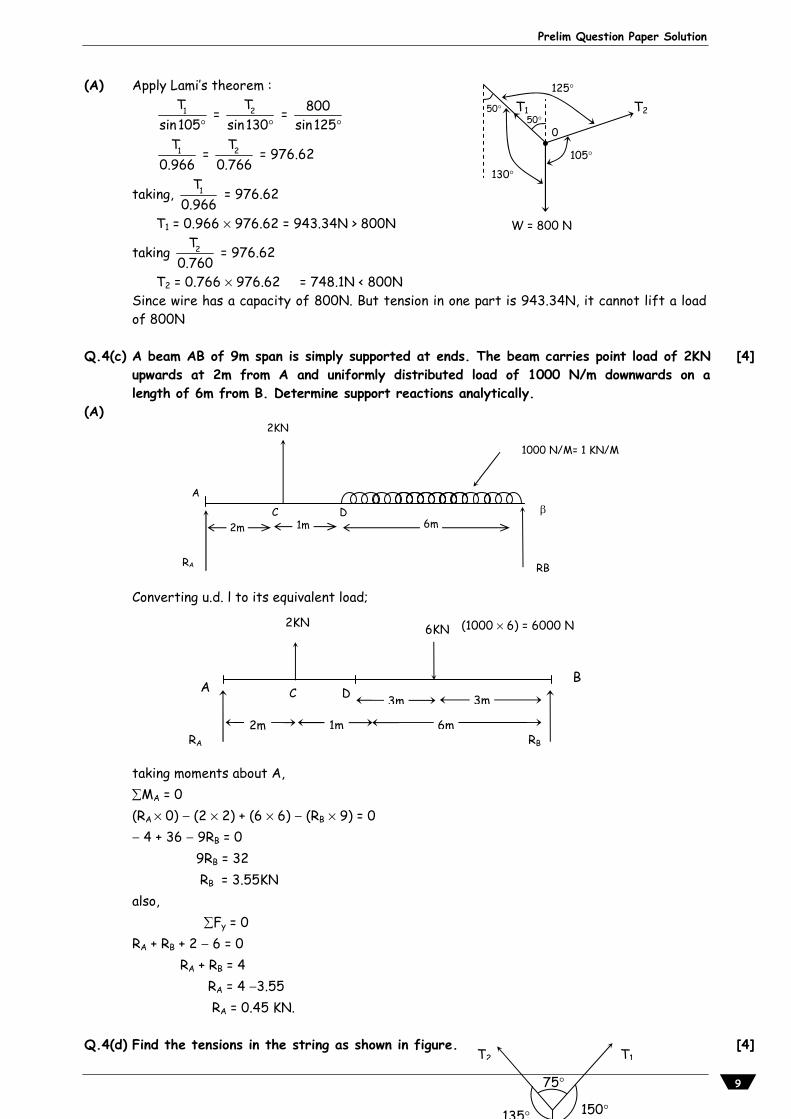
(A) Apply Lami’s theorem :
1T
sin 105 =
2T
sin 130 =
800
sin125
1T0.966
= 2T0.766
= 976.62
taking, 1T0.966
= 976.62
T1 = 0.966 976.62 = 943.34N > 800N
taking 2T0.760
= 976.62
T2 = 0.766 976.62 = 748.1N < 800N Since wire has a capacity of 800N. But tension in one part is 943.34N, it cannot lift a load of 800N
Q.4(c) A beam AB of 9m span is simply supported at ends. The beam carries point load of 2KN
upwards at 2m from A and uniformly distributed load of 1000 N/m downwards on alength of 6m from B. Determine support reactions analytically.
[4]
(A) Converting u.d. l to its equivalent load;
taking moments about A, MA = 0 (RA 0) (2 2) + (6 6) (RB 9) = 0 4 + 36 9RB = 0 9RB = 32 RB = 3.55KN also, Fy = 0 RA + RB + 2 6 = 0 RA + RB = 4 RA = 4 3.55 RA = 0.45 KN.
Q.4(d) Find the tensions in the string as shown in figure. [4]
150 135
75
T1T2
W = 800 N
50
130
105
125
T2 T1 50
0
1000 N/M= 1 KN/M
A
6m
RB
2KN
DC
RA
1m 2m
A
RA RB
2m 1m 6m
3m 3mC D
2KN 6KN
B
(1000 6) = 6000 N

Vidyalankar : F.Y. Diploma Engineering Mechanics
10
(A)
Using Lami's theorem,
1 2
(1) (2) (3)
T T25sin75 sin135 sin150
Using term (1) and (2) Using term (1) and (3)
1T25sin75 sin135
2T25sin75 sin150
T1 = sin135 X25sin75
T2 = sin150 X25sin75
T1 = 18.301N T2 = 13.940N Q.4(e) Two men carry a weight 200 N by means of ropes fixed to the weight. One rope is
inclined at 45 and other 30 with the vertical. Find tension in each side of rope. [4]
(A) Using Lami's theorem,
1 2T TWsin75 sin150 sin135
2
(1) (2) (3)
T200 Tsin75 sin150 sin135
Using term (1) and (2)

Prelim Question Paper Solution
11
1T200sin75 sin150
T1 = 200
sin150sin75
T1 = 103.527 N Using term (1) and (3)
2T200sin75 sin135
T2 = 200
sin135sin75
T2 = 146.410 N Q.4(f) Find the support reactions of simply supported beam shown in figure.
[4]
(A)
(i) Equivalent point load and it's position Equivalent point load = Intensity of udl = 5 3 = 15 N Position from RA= 7m + Span of udl / 2 = 7 + (3/2) = 8.5 m (ii) Applying equilibrium conditions Fy = 0 ( +ve, ve) and M = 0 ( +ve, ve) Fy = 0 RA + 10 20 15 + RB = 0 RA + RB = 25 N … (1) MA = 0 Taking moment of all forces @ point A (RA 0) (10 3) + (20 7) + (15 8.5) (RB 10) = 0 RB = 23.75 N Putting value of RB in equation (1) RA + 23.75 = 25 RA = 1.25 N Q.5 Attempt any FOUR of the following : [16]Q.5(a) A Ladder of weight 400N and length 10m is supported on smooth well with its lower
end 4m from the wall. The coefficient of friction between the flower and the ladder is[4]
10 N 20 N
3 m 4 m 3 m
5

Vidyalankar : F.Y. Diploma Engineering Mechanics
12
0.3. Show the forces acting on the ladder and find frictional force at floor. (A) sin = 4/10 = sin1 (4/10) = 23.58 Fx = 0 RW EF = 0 RW = FF
Fy = 0 FW + RF W = 0 0 + RF 400 = 0 RF = 400 N MA = 0 FF L cos RF 4 + 400 2 + RW 0 = 0 FF 10 cos 23.58 400 4 + 800 = 0 FF 10 cos 23.58 = 1600 800 = 800
FF =
80010 cos23.58
= 87.25 N
Ans. : (i) RW = FF = 87.29N (ii) RF = 400 N (iii) FW = 0 Q.5(b) For a certain machine an effort of 100 N and 150 N can lift a load of 1 kN and 2kN
respectively. Find the law of machine. Also calculate maximum efficiency if VR is 20. [4]
(A) Effort (P) = 100 N and W = 1 kN = 1000 N Effort (P) = 150 N and W = 2 kN = 2000 N (i) Law of machine P = mW + C 100 = m 1000 + C (1) 150 = m 2000 + C (2) Multiplying equation (1) by 2 1000 m + C = 100 2 2000 m + C = 150 Subtracting equation (2) from equation (1) 2000 m + 2C = 200 (1) 2000 m + C = 150 (2) C = 50 N put in equation (2) 150 = m 2000 + 50 150 50 = 2000 m 100 = 2000 m m = 0.05 (ii) Law of machine P = (0.05W + 50) N
(iii) Max.M.A. = 1m
= 10.05
Max M.A. = 20
A RW
B 2m 2m
5m
5m
smooth wall W = 0
FW = RW W = 0
G
D
RF
Ff = FRF = 0.3 RF
W = 400N
C
L co
s

Prelim Question Paper Solution
13
(iv) Max. = Max.M.A. 20100 100V.R. 20
Max. = 100 % Q.5(c) A block of weight 500 N is placed on a inclined plane at an angle of 20 with the
horizontal. If coefficient of friction is 0.14, find the force ‘P’ applied Parallel to theplane, just to move the body up the plane.
[4]
(A) Fy = 0 R 500 cos 20 = 0 R = 469.85 N Fx = 0 P 500 sin 20 R = 0 P = 500 sin 20 + R = 171.01 + 0.14 469.85 P = 236.789N
Q.5(d) The velocity ratio of a certain machine is 72. The law of machine is
P =
1 W 30
48N. Find the maximum mechanical advantage and maximum efficiency.
State also whether the machine is reversible or not.
[4]
(A) VR = 72
P =
1 W 30 N
48
m = 148
and c = 30N
(i) Maximum M.A. = ? (ii) Maximum = ? (iii) To decide whether the machine is reversible or not.
(i) Maximum M.A. = 1m
= 11 / 48
= 48
(ii) Maximum =
1 100m V.R.
=
1 1001 / 48 72
= 66.67% > 50%
(iii) Since the maximum efficiency is more than 50%, the machine is reversible. Q.5(e) A block of 80 N is placed on a horizontal plane where the coefficient of friction is
0.25. Find the force at 30 up the horizontal to just move the block [4]
(A)
For limiting equilibrium ( +ve, ve)
500N
500 cos 20
motion
500 sin 20 F = R
R P
20 20

Vidyalankar : F.Y. Diploma Engineering Mechanics
14
( +ve, ve) Fy = 0 + R W = 0 R = W = 2000 N R = 2000 N
Fx = 0 + P F = 0 + P = F P = R Since F = R P = 0.4 2000 P = 800 N
Q.5(f) Find the horizontal force required to drag a body of weight 100 N along a horizontal
plane. If the plane is raised gradually upto 15, the body will begin to slide. [4]
(A)
We know, = tan = tan 15 = 0.27
For limiting equilibrium ( +ve, ve)
( +ve, ve)
Fy = 0 + R W = 0 R = W = 100 N R = 100 N
Fx = 0 + P F = 0 + P = F P = R Since F = R P = 0.27 100 P = 27 N
Q.6 Attempt any FOUR of the following : [16]Q.6(a) Locate the centroid of angle section 90 mm 100 mm 10 mm. (90 mm side is
vertical.) [4]
(A) (i) a1 = 80 10 = 800 mm2 a2 = 100 10 = 1000 mm2
(ii) x1 = 102
= 5 mm
x2 = 1002
= 50 mm
y1 = 10 + 802
= 10 + 40 = 50 mm
y2 = 102
= 5 mm
1x =
1 1 2 2
1 2
a x a xa a
=
800 5 1000 50800 1000´ ´
x = 30 mm

Prelim Question Paper Solution
15
y =
1 1 2 2
1 2
a y a ya a
=
800 50 1000 5
800 1000´ ´
´
y = 25 mm Q.6(b) Find the centroid of the I-section with following details.
(i) Top flange = 200 mmx 10mm (ii) Bottom flange = 100 mm 20 mm (iii) Web thickness = 15 mm (iv) over all depth = 250 mm
[4]
(A) x = x1 = x2 = 2002
= 100 mm
a1 = 200 10 = 2000 mm2
a2 = 15 220 = 3300 mm2
a3 = 100 20 = 2000 mm2
A = a1 + a2 + a3 = 2000 + 3300 + 2000 = 7300 mm2
y1 = 20 + 220 + 10/2 = 245 mm
y2 = 220202
= 130mm,
y3 = 20/2 = 10 mm
y = 1 1 2 2 3 3a y a y a y
A = 2000 235 3300 130 2000 10
7300
y = 919007300
= 125.89 mm.
a x, y = (100 mm, 125.89 mm) Q.6(c) A wall of height 6m has one side vertical and other inclined. The top thickness is 1 m
and bottom thickness is 4 m. Find its centroid. [4]
(A) From given data, Divide the section of retaining wall into rectangle (1) and triangle (2) and taking the
complete section of retaining wall in first quadrant A1 = 1 6 = 6m2
A2 = 1 3 62
= 9m2
X1 =12
= 0.5m
X2 = 113
= 2
= 2 m … wrt to OY
Y2 = 1 63
= 2m …. wrt to OX.
X =
1 1 2 2
1 2
A X A XA A
=
6 0.5 9 26 9
= 1.4m
Y =
1 1 2 2
1 2
A Y A YA A
=
6 3 9 26 9
= 2.4m
G x,y = G 1.4m, 2.4m
Q.6(d) A square of 400 mm side from which a circle of 400 mm diameter is cut-off from the
centre. Find centroid of the remaining area. [4]
(A)
1
2
3
200 mm
250 mm 15 mm
20 mm
100 mm
10 mm

Vidyalankar : F.Y. Diploma Engineering Mechanics
16
(i) Area calculation A1 = 400 400 = 160000 mm2 A2 = ( / 4) (400)2 = 125663.706 mm2 A = A1 = A2 = 34336.293 mm2 (ii) Location of x x1 = 400 / 2 = 200 mm x2 = 400 / 2 = 200 mm
1 1 2 2A x A xx
A
x = 200mm (iii) Location of y y1 = 400 / 2 = 200 mm y2 = 400 / 2 = 200 mm
1 1 2 2A y A yy
A
y = 200mm Hence, centroid (G) for given section lies at G x, y
= (200 mm from oB and 200 mm from OA) Q.6(e) Locate the position of centroid of an ice-cream cone as shown in figure. [4]
(A)

Prelim Question Paper Solution
17
Note : Considering Centroid (i) Figure is symmetric @ y y axis and hence, x = Maximum horizontal dimension / 2 = 200 / 2 = 100 mm (ii) Area Calculation
A1 = 11 1bh 200 6002 2
= 60000mm2
A2 =
22 100r
2 2 = 15707.96mm2
A = A1 + A2 = 75707.96mm2 (iii) y calculation
y1 = 12 2h 6003 3
= 400 mm
y2 = h1 +
4r 4 1006003 3
= 642.44mm
y = 1 1 2 2A y A yA
y = 450.30 mm Hence, centroid (G) for given ice cream cone lies at G x, y
= (100 mm from OB and 450.30 mm from OA)
OR Note : Considering Center of Gravity of ice-cream cone. (i) Figure is symmetric @ y-y axis and hence, x = Maximum horizontal dimension / 2 = 200 / 2 = 100 mm (ii) Volume Calculation V1 = (1/3) 2
1r = (1/3)(100)2 600 = 6.28318 106 mm3
V2 = (2/3) 32r = (2/3)(100)3 = 2.094395 106 mm3
V = V1 + V2 = 8.377575 106 mm3 (iii) y calculation
y1 = 11
h 600h 6004 4
= 450mm
y2 =
21
3r 3 100h 6008 8
= 637.5mm

Vidyalankar : F.Y. Diploma Engineering Mechanics
18
y = 1 1 2 2V y V yV
y = 496.875mm Hence, Centre of Gravity (G) for given ice cream cone lies G x, y
= (100 mm from OB and 496.875 mm from OA) Q.6(f) The frustum of a cone has top diameter 40 cm and bottom diameter 60 cm with
height 18 cm. Calculate Y only. [4]
(A)
Let, Full cone as figure 1 and cut cone as figure 2 (i) Figure is symmetric @ y y axis and hence, x = Maximum horizontal dimension / 2 = 60 / 2 = 30 cm h1 = 18 cm, h2 = Height of cut cone In triangle, ABE and CDE
2hh60 40
h = 260 h40
h = 1.5h2 h1 + h2 = h h1 + h2 = 1.5h2 h1 = 1.5h2 h2 h1 = 0.5h2 18 = 0.5h2 h2 = 36cm h = 18 + 36 = 54cm (ii) Volume Calculation V1 = (1/3) 2
1r h = (1/3)(30)2 x 54 = 50.86 103 cm3
V2 = (1/3) 22r h+ = (1/3)(20)2 36 = 15.07 103 cm3
V = V1 V2 = 35.82 10 cm3

Prelim Question Paper Solution
19
(iii) y calculation
y1 = h 544 4
= 13.5cm
y2 =
2
1
h 36h 184 4
= 27 cm
y = 1 1 2 2V y V yV
y = 7.815 cm Hence, centre of gravity (G) for given frustum of cone lies at G x, y
= (30 cm from AQ and 7.815 cm from AP)