engineering metrology - iitkhome.iitk.ac.in/~jrkumar/download/lecture-4.pdf · introduction to...
TRANSCRIPT
Engineering Metrology
Prof. J. Ramkumar
Department of Mechanical EngineeringIIT Kanpur
October 24, 2017
Outline
Introduction and Types of Instruments
Engineering Tolerance
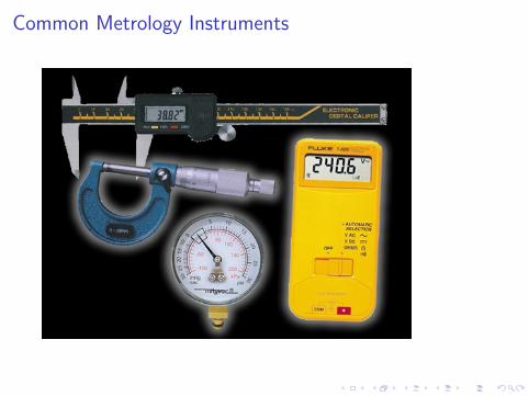
Common Metrology Instruments
Common Metrology Instruments
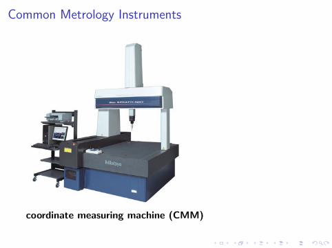
coordinate measuring machine (CMM)
Introduction to Metrology
I Metrology is the science of measurement
I Dimensional metrology is that branch of Metrology whichdeals with measurement of dimensions of a part or workpiece(lengths, angles, etc.)
I Dimensional measurements at the required level of accuracyare the essential link between the designer’s intent and adelivered product.
I The width, depth, angles and other dimensions all must beproduced and measured accurately for the machine tool tofunction as expected.
I Note: Metrology is a vast area. In this lecture, the mainfocus on Dimensional Metrology
Dimensional Metrology Needs
I Linear measurements
I Angular measurements
I Geometric form measurements(Roundness, Straightness,Cylindricity, Flatness etc.)
I Geometric relationships(Parallel, perpendicular,Concentric,runout etc.)
I Controlled surface texture
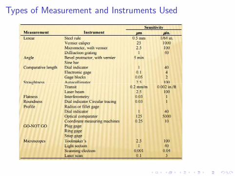
Types of Measurement and Instruments Used
Linear Measurement Devices
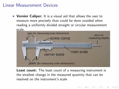
I Vernier Caliper: It is a visual aid that allows the user tomeasure more precisely than could be done unaided whenreading a uniformly divided straight or circular measurementscale.
Least count: The least count of a measuring instrument isthe smallest change in the measured quantity that can beresolved on the instrument’s scale
Linear Measurement Devices
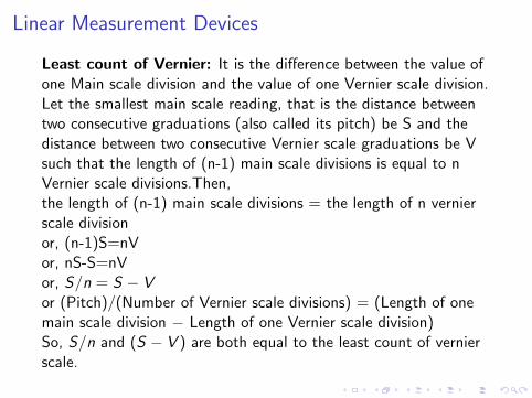
Least count of Vernier: It is the difference between the value ofone Main scale division and the value of one Vernier scale division.Let the smallest main scale reading, that is the distance betweentwo consecutive graduations (also called its pitch) be S and thedistance between two consecutive Vernier scale graduations be Vsuch that the length of (n-1) main scale divisions is equal to nVernier scale divisions.Then,the length of (n-1) main scale divisions = the length of n vernierscale divisionor, (n-1)S=nVor, nS-S=nVor, S/n = S − Vor (Pitch)/(Number of Vernier scale divisions) = (Length of onemain scale division − Length of one Vernier scale division)So, S/n and (S − V ) are both equal to the least count of vernierscale.
Linear Measurement Devices
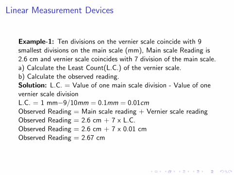
Example-1: Ten divisions on the vernier scale coincide with 9smallest divisions on the main scale (mm), Main scale Reading is2.6 cm and vernier scale coincides with 7 division of the main scale.a) Calculate the Least Count(L.C.) of the vernier scale.b) Calculate the observed reading.Solution: L.C. = Value of one main scale division - Value of onevernier scale divisionL.C. = 1 mm−9/10mm = 0.1mm = 0.01cmObserved Reading = Main scale reading + Vernier scale readingObserved Reading = 2.6 cm + 7 x L.C.Observed Reading = 2.6 cm + 7 x 0.01 cmObserved Reading = 2.67 cm
Linear Measurement Devices
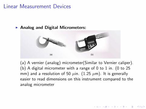
I Analog and Digital Micrometers:
(a) A vernier (analog) micrometer(Similar to Vernier caliper).(b) A digital micrometer with a range of 0 to 1 in. (0 to 25mm) and a resolution of 50 µin. (1.25 µm). It is generallyeasier to read dimensions on this instrument compared to theanalog micrometer
Angle Measuring Instruments
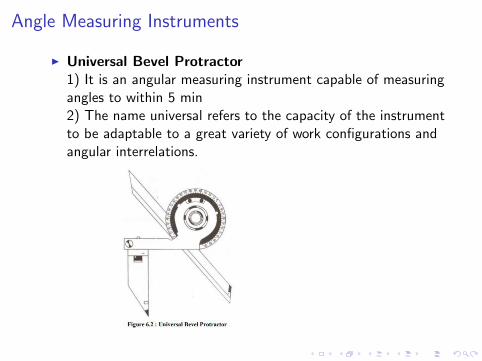
I Universal Bevel Protractor1) It is an angular measuring instrument capable of measuringangles to within 5 min2) The name universal refers to the capacity of the instrumentto be adaptable to a great variety of work configurations andangular interrelations.
Angle Measuring Instruments
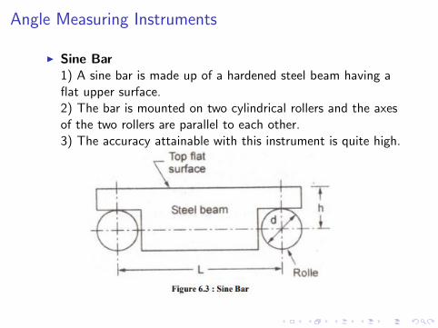
I Sine Bar1) A sine bar is made up of a hardened steel beam having aflat upper surface.2) The bar is mounted on two cylindrical rollers and the axesof the two rollers are parallel to each other.3) The accuracy attainable with this instrument is quite high.

Angle Measuring InstrumentsUse of Sine Bar for Angle Measurement
sinθ =h
L(1)
For error in angle measurement, differentiating h with respect to θ,we have
dθ
dh=
secθ
L(2)
Therefore, the error in angle measurement dθ, due to an error dhin height h is proportional to secθ.
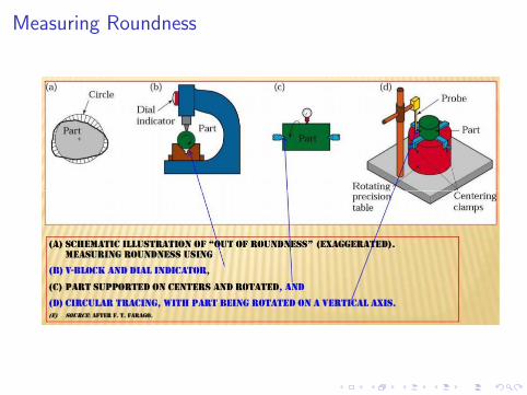
Measuring Roundness
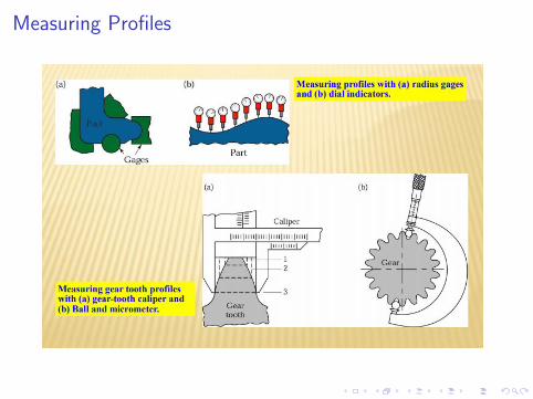
Measuring Profiles
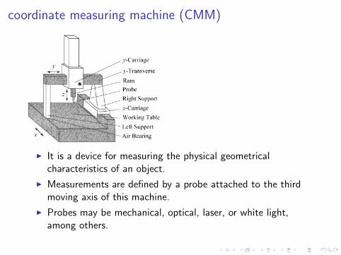
coordinate measuring machine (CMM)
I It is a device for measuring the physical geometricalcharacteristics of an object.
I Measurements are defined by a probe attached to the thirdmoving axis of this machine.
I Probes may be mechanical, optical, laser, or white light,among others.

Repeatability
I Repeatability is the consistency of a single appraiser tomeasure the same part multiple times with the samemeasurement system.
I it is related to the standard deviation of the measured values.
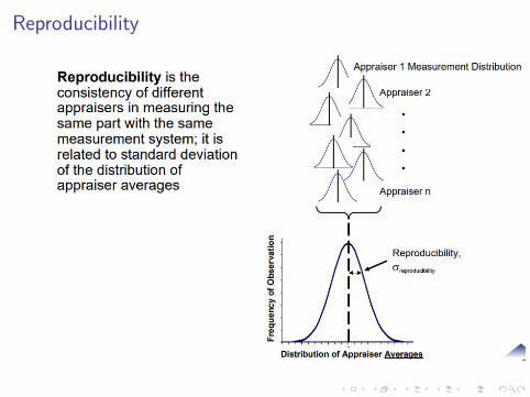
Reproducibility
Measurement Error
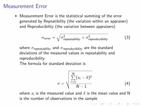
I Measurement Error is the statistical summing of the errorgenerated by Repeatibility (the variation within an appraiser)and Reproducibility (the variation between appraisers)
σerror =√σ2repeatability + σ2reproducibility (3)
where σrepeatability and σreproducibility are the standarddeviations of the measured values in repeatability andreproducibility.The formula for standard deviation is
σ =
√√√√√ N∑i=1
(xi − x̄)2
N − 1(4)
where xi is the measured value and x̄ is the mean value and Nis the number of observations in the sample
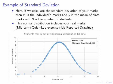
Example of Standard DeviationI Here, if we calculate the standard deviation of your marks
then xi is the individual’s marks and x̄ is the mean of classmarks and N is the number of students.
I This normal distribution includes your real marks(Mid-sem+Quiz+Lab exercise+lab Reports+Drawing)
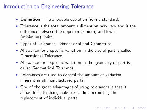
Introduction to Engineering Tolerance
I Definition: The allowable deviation from a standard.
I Tolerance is the total amount a dimension may vary and is thedifference between the upper (maximum) and lower(minimum) limits.
I Types of Tolerance: Dimensional and Geometrical
I Allowance for a specific variation in the size of part is calledDimensional Tolerance.
I Allowance for a specific variation in the geometry of part iscalled Geometrical Tolerance.
I Tolerances are used to control the amount of variationinherent in all manufactured parts.
I One of the great advantages of using tolerances is that itallows for interchangeable parts, thus permitting thereplacement of individual parts.
Tolerance in relation to Cost
I Cost generally increases with smaller tolerance-Small tolerances cause an exponential increase in cost-Therefore your duty as an engineer have to consider : Doyou need φ1.0001cm or is 1.01cm good enough?
I Parts with small tolerances often require special methods ofmanufacturing.
I Parts with small tolerances often require greater inspectionand call for the rejection of parts → Greater QualityInspection → Greater cost.
I Do not specify a smaller tolerance than is necessary!

Dimensional Tolerance representation
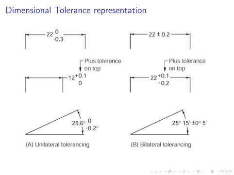
Dimensional Tolerance representation
Important Terms in Tolerancing
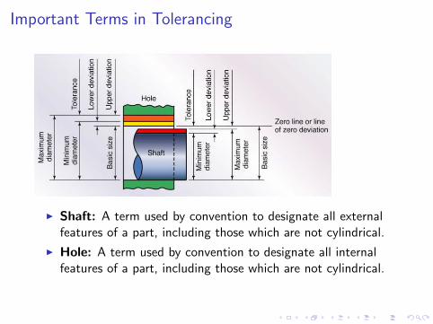
I Shaft: A term used by convention to designate all externalfeatures of a part, including those which are not cylindrical.
I Hole: A term used by convention to designate all internalfeatures of a part, including those which are not cylindrical.
Important Terms in Tolerancing
I Basic Size: the nominal diameter of the shaft (or bolt) andthe hole. This is, in general, the same for both components.
I Actual Size: the measured size of the finished part aftermachining.
I Zero Line: It is a straight line corresponding to the basicsize. The deviations are measured from this line. The positiveand negative deviations are shown above and below the zeroline respectively.
I Limits of Size: The term limits of size referred to the twoextreme permissible sizes for a dimension of a part(hole orshaft), between which the actual size should lie.
I Maximum Limit of Size: The greater of the two limits ofsize of a part(Hole or shaft).
Important Terms in Tolerancing
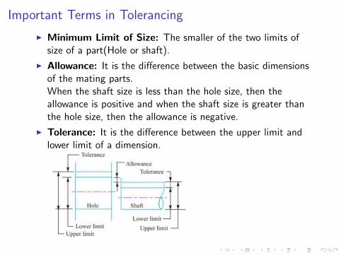
I Minimum Limit of Size: The smaller of the two limits ofsize of a part(Hole or shaft).
I Allowance: It is the difference between the basic dimensionsof the mating parts.When the shaft size is less than the hole size, then theallowance is positive and when the shaft size is greater thanthe hole size, then the allowance is negative.
I Tolerance: It is the difference between the upper limit andlower limit of a dimension.
Important Terms in Tolerancing
I Tolerance Zone: It is the zone between the maximum andminimum limit size.
I Upper Deviation: It is the algebraic difference between themaximum size and the basic size.The upper deviation of a hole is represented by a symbol ES(Ecart Superior) and of a shaft, it is represented by es.
I Lower Deviation: It is the algebraic difference between theminimum size and the basic size.The lower deviation of a hole is represented by a symbol EI(Ecart Inferior) and of a shaft, it is represented by ei.
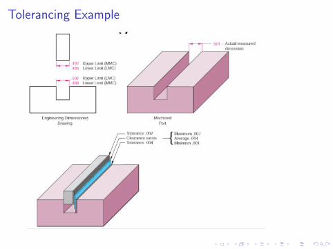
Tolerancing Example
Fit Types
I Clearance fit occurs when two toleranced mating parts willalways leave a space or clearance when assembled.
I Interference fit occurs when two toleranced mating parts willalways interfere when assembled.
I Transition fit occurs when two toleranced mating parts willsometimes be an interference fit and sometimes be a clearancefit when assembled.
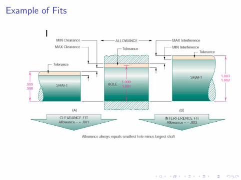
Example of Fits
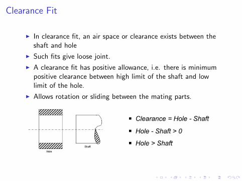
Clearance Fit
I In clearance fit, an air space or clearance exists between theshaft and hole
I Such fits give loose joint.
I A clearance fit has positive allowance, i.e. there is minimumpositive clearance between high limit of the shaft and lowlimit of the hole.
I Allows rotation or sliding between the mating parts.
Types of Clearance Fit
I Loose Fit: It is used between those mating parts where noprecision is required. It provides minimum allowance and isused on loose pulleys, agricultural machineries etc.
I Running Fit: For a running fit, the dimension of shaft shouldbe smaller enough to maintain a film of oil for lubrication. Itis used in bearing pair etc.
I Slide Fit or Medium Fit: It is used on those mating partswhere great precision is required. It provides mediumallowance and is used in tool slides, slide valve, automobileparts, etc.
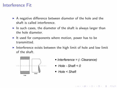
Interference Fit
I A negative difference between diameter of the hole and theshaft is called interference.
I In such cases, the diameter of the shaft is always larger thanthe hole diameter.
I It used for components where motion, power has to betransmitted.
I Interference exists between the high limit of hole and low limitof the shaft.
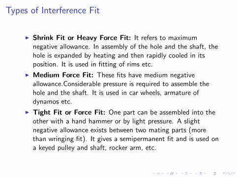
Types of Interference Fit
I Shrink Fit or Heavy Force Fit: It refers to maximumnegative allowance. In assembly of the hole and the shaft, thehole is expanded by heating and then rapidly cooled in itsposition. It is used in fitting of rims etc.
I Medium Force Fit: These fits have medium negativeallowance.Considerable pressure is required to assemble thehole and the shaft. It is used in car wheels, armature ofdynamos etc.
I Tight Fit or Force Fit: One part can be assembled into theother with a hand hammer or by light pressure. A slightnegative allowance exists between two mating parts (morethan wringing fit). It gives a semipermanent fit and is used ona keyed pulley and shaft, rocker arm, etc.
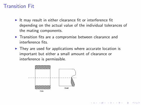
Transition Fit
I It may result in either clearance fit or interference fitdepending on the actual value of the individual tolerances ofthe mating components.
I Transition fits are a compromise between clearance andinterference fits.
I They are used for applications where accurate location isimportant but either a small amount of clearance orinterference is permissible.
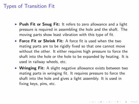
Types of Transition Fit
I Push Fit or Snug Fit: It refers to zero allowance and a lightpressure is required in assembling the hole and the shaft. Themoving parts show least vibration with this type of fit.
I Force Fit or Shrink Fit: A force fit is used when the twomating parts are to be rigidly fixed so that one cannot movewithout the other. It either requires high pressure to force theshaft into the hole or the hole to be expanded by heating. It isused in railway wheels, etc.
I Wringing Fit: A slight negative allowance exists between twomating parts in wringing fit. It requires pressure to force theshaft into the hole and gives a light assembly. It is used infixing keys, pins, etc.
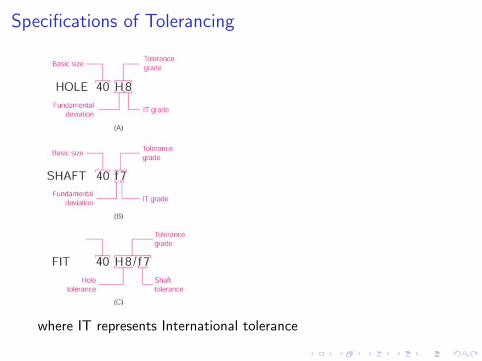
Specifications of Tolerancing
where IT represents International tolerance
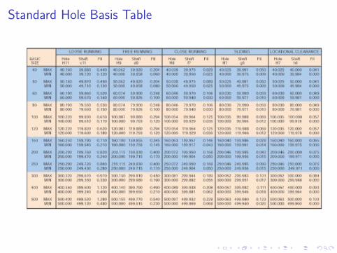
Standard Hole Basis Table
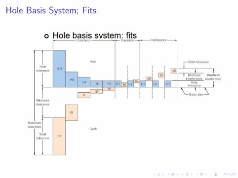
Hole Basis System; Fits
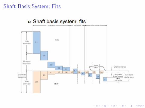
Shaft Basis System; Fits
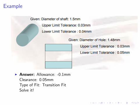
Example
I Answer: Allowance: -0.1mmClearance: 0.05mmType of Fit: Transition FitSolve it!

...........
Thank You