engineering operation & maintenance - psg · specialty codes section 2 wilden pump designation...
TRANSCRIPT

EOMEngineering
Operation &Maintenance
wildenpump.com
Where Innovation Flows
P1Metal Pump

T A B L E O F C O N T E N T S
SECTION 1 CAUTIONS—READ FIRST! . . . . . . . . . . . . . . . . . . . . . . . . . . . . . . . . . . . . . . . . . . . . . .1
SECTION 2 WILDEN PUMP DESIGNATION SYSTEM . . . . . . . . . . . . . . . . . . . . . . . . . . . . . . . . .2
SECTION 3 HOW IT WORKS—PUMP & AIR DISTRIBUTION SYSTEM . . . . . . . . . . . . . . . .3
SECTION 4 DIMENSIONAL DRAWINGS . . . . . . . . . . . . . . . . . . . . . . . . . . . . . . . . . . . . . . . . . . . . .4
SECTION 5 PERFORMANCE
A . P1 Performance Curves
Rubber-Fitted . . . . . . . . . . . . . . . . . . . . . . . . . . . . . . . . . . . . . . . . . . . . . . . . . . . . . . . .5
TPE-Fitted . . . . . . . . . . . . . . . . . . . . . . . . . . . . . . . . . . . . . . . . . . . . . . . . . . . . . . . . . . .5
PTFE-Fitted . . . . . . . . . . . . . . . . . . . . . . . . . . . . . . . . . . . . . . . . . . . . . . . . . . . . . . . . . .6
B . Suction-Lift Curves . . . . . . . . . . . . . . . . . . . . . . . . . . . . . . . . . . . . . . . . . . . . . . . . . . . . .7
SECTION 6 SUGGESTED INSTALLATION, OPERATION & TROUBLESHOOTING . . . . . . . .8
SECTION 7 DISASSEMBLY / REASSEMBLY . . . . . . . . . . . . . . . . . . . . . . . . . . . . . . . . . . . . . . . . 11
SECTION 8 EXPLODED VIEW & PARTS LISTING
P1 Metal Rubber/TPE-Fitted . . . . . . . . . . . . . . . . . . . . . . . . . . . . . . . . . . . . . . . . . . . . . . . .18
P1 Metal PTFE-Fitted . . . . . . . . . . . . . . . . . . . . . . . . . . . . . . . . . . . . . . . . . . . . . . . . . . . . .20
P1 Metal Saniflo™ 1935/2004/EC . . . . . . . . . . . . . . . . . . . . . . . . . . . . . . . . . . . . . . . . . . . .22
SECTION 9 ELASTOMER OPTIONS . . . . . . . . . . . . . . . . . . . . . . . . . . . . . . . . . . . . . . . . . . . . . . . . .24
Cla
ss
I & II Ozone
Depleting Substanc
esNON
USEU.S. Clean Air Act
Amendments of 1990

S e c t i o n 1
C A U T I O N S — R E A D F I R S T !
CAUTION: Do not apply compressed air to the exhaust port — pump will not function.
CAUTION: Do not over-lubricate air supply — excess lubrication will reduce pump performance. Pump is pre-lubed.
TEMPERATURE LIMITS: Polypropylene 0°C to 79°C 32°F to 175°F PVDF –12°C to 107°C 10°F to 225°F PFA 7°C to 107°C 20°F to 225°F Neoprene –18°C to 93°C 0°F to 200°F Buna-N –12°C to 82°C 10°F to 180°F EPDM –51°C to 138°C –60°F to 280°F FKM –40°C to 177°C –40°F to 350°F Wil-Flex™ –40°C to 107°C –40°F to 225°F Saniflex™ –29°C to 104°C –20°F to 220°F Polyurethane –12°C to 66°C 10°F to 150°F Polytetrafluoroethylene (PTFE)1 4°C to 104°C 40°F to 220°F Nylon –18°C to 93°C 0°F to 200°F Acetal –29°C to 82°C –20°F to 180°F SIPD PTFE with Neoprene-backed 4°C to 104°C 40°F to 220°F SIPD PTFE with EPDM-backed –10°C to 137°C 14°F to 280°F Polyethylene 0°C to 70°C 32°F to 158°F Geolast® –40°C to 82°C –40°F to 180°F
1 4°C to 149°C (40°F to 300°F) - 13 mm (1/2") and 25 mm (1") models only.
NOTE: Not all materials are available for all models. Refer to Secton 2 for material options for your pump.
NOTE: UL-listed configured pumps have the folllowing temperature limits: UL 79 Buna-N =12.2°C to 52°C (10°F to 125°F).
CAUTION: When choosing pump materials, be sure to check the temperature limits for all wetted components. Example: FKM has a maximum limit of 177°C (350°F) but polypropylene has a maximum limit of only 79°C (175°F).
CAUTION: Maximum temperature limits are based upon mechanical stress only. Certain chemicals will significantly reduce maximum safe operating temperatures. Consult Chemical Resistance Guide for chemical compatibility and temperature limits.
WARNING: Prevent Static Sparking. If static sparking occurs, fire or explosion could result. Pump, valves and containers must be grounded to a proper grounding point when handling flammable fluids and whenever discharge of static electricity is a hazard.
CAUTION: Do not exceed 8.6 bar (125 psig) air supply pressure.
CAUTION: For UL-listed pumps, do not exceed 3.4 bar (50 psig) air supply pressure.
CAUTION: The process fluid and cleaning fluids must be chemically compatible with all wetted pump components. Consult Chemical Resistance Guide (E4).
CAUTION: Do not exceed 82°C (180°F) air inlet temperature for all models.
CAUTION: Pumps should be thoroughly flushed before installing into process lines. FDA- and USDA-approved pumps should be cleaned and/or sanitized before being used.
CAUTION: Always wear safety glasses when operating pump. If diaphragm rupture occurs, material being pumped may be forced out air exhaust.
CAUTION: Before any maintenance or repair is attempted, the compressed air line to the pump should be disconnected and all air pressure allowed to bleed from pump. Disconnect all intake, discharge and air lines. Drain the pump by turning it upside down and allowing any fluid to flow into a suitable container.
CAUTION: Blow out air line for 10 to 20 seconds before attaching to pump to make sure all pipeline debris is clear. Use an in-line air filter. A 5μ (micron) air filter is recommended.
NOTE: When installing PTFE diaphragms, it is important to tighten outer pistons simultaneously (turning in opposite directions) to ensure tight fit. (See torque specifications.)
NOTE: Some PTFE-fitted pumps come standard from the factory with expanded PTFE gaskets installed in the diaphragm bead of the liquid chamber. PTFE gaskets cannot be re-used.
NOTE: Before starting disassembly, mark a line from each liquid chamber to its corresponding air chamber. This line will assist in proper alignment during reassembly.
CAUTION: Pro-Flo® pumps cannot be used in submersible applications.
CAUTION: Tighten all hardware prior to installation.
CAUTION: For UL-listed pumps, all pipe connections are to be made using U.L. classified gasoline-resistant pipe compound.
CAUTION: For UL-listed pumps all installations must conform to NFPA 30, NFPA 30A, and all other applicable codes.
CAUTION: For UL-listed pumps, air exhaust port is to be connected to pipe or tubing to be routed outdoors or other location determined to be equivalent.
CAUTION: For UL-listed pumps, pump is to be grounded using the jam-nut located at the top of the long vertical carriage bolt. The ground connection is marked with a tag having the grounding symbol.
WIL-10300-E-19 1 WILDEN PUMP & ENGINEERING, LLC

SPECIALTY CODES
S e c t i o n 2
W I L D E N P U M P D E S I G N A T I O N S Y S T E M
P1/PX1 METAL13 mm (½") PumpMaximum Flow Rate:62.8 lpm (16.6 gpm)
MATERIAL CODES
MODELP1 = Pro-Flo®
WETTED PARTS & OUTER PISTONAA = ALUMINUM / ALUMINUMAZ = ALUMINUM / NO PISTONSS = STAINLESS STEEL /
STAINLESS STEELSZ = STAINLESS STEEL /
NO PISTON
CENTER SECTIONGG = CONDUCTIVE ACETALJJ = CONDUCTIVE
POLYPROPYLENELL = ACETALPP = POLYPROPYLENE
AIR VALVEG = CONDUCTIVE ACETALJ = CONDUCTIVE
POLYPROPYLENEL = ACETALP = POLYPROPYLENE
DIAPHRAGMSBNS = BUNA-N (Red Dot)EPS = EPDM (Blue Dot)FSS = SANIFLEX™
[Hytrel® (Cream)] 1,3
PUS = POLYURETHANE (Clear)TEU = PTFE w/EPDM
BACK-UP (White) 1,2,3
THU = PTFE W/HIGH-TEMP BUNA-N BACKUP (White)
TNL = PTFE W/NEOPRENE BACK-UP O-RING, IPD (White)
TNU = PTFE W/NEOPRENE BACK-UP (White)TSU = PTFE W/SANIFLEX™
BACK-UP (White) 1,2,3
TVU = PTFE W/FKM BACKUPVTS = FKM (White Dot)WFS = WIL-FLEX™ [Santoprene®
(Three Black Dots)]XBS = CONDUCTIVE BUNA-N
(Two Red Dots)
VALVE BALLSBN = BUNA-N (Red Dot)EP = EPDM (Blue Dot)FS = SANIFLEX™
[Hytrel® (Cream)] 1,3
PU = POLYURETHANE (Brown)TF = PTFE (White) 1,2,3
VT = FKM (White Dot)WF = WIL-FLEX™ [Santoprene®
(Three Black Dots)]VALVE SEATA = ALUMINUMH = ALLOY CS = STAINLESS STEELV = FKM (White Dot)
VALVE SEAT O-RINGBN = BUNA-NEP = EPDMFS = SANIFLEX™
[Hytrel® (Cream)] 1,3
PU = POLYURETHANE (Brown)TF = PTFE (White) 1,2,3
WF = WIL-FLEX™ [Santoprene®]
LEGEND XPX1 / XXXXX / XXX / XX / X XX / XXXX
O-RINGSMODEL VALVE SEAT
VALVE BALLSATEX DIAPHRAGMS
AIR VALVECENTER SECTION
WETTED PARTS & OUTER PISTON
SPECIALTYCODE(if applicable)
NOTE: Wilden UL-Listed pumps have been evaluated for use at a 25°C (77°F) ambient temperature with a maximum inlet pressure of 3.4 bar (50 psi).
0103 Wil-Gard II™ 220V0120 Saniflo™ FDA, Wil-Gard II™ 110V0206 PFA-coated hardware, Wil-Gard II™
sensor wires ONLY0390 CSA-approved0495 UL-approved0502 PFA-coated hardware
0023 Wing nuts0067 Saniflo™ FDA, Wil-Gard II™ 220V0070 Saniflo™ FDA0079 Tri-clamp fittings, wing nuts0080 Tri-clamp fittings ONLY0100 Wil-Gard II™ 110V0102 Wil-Gard II™ sensor wires ONLY
0603 PFA-coated hardware, Wil-Gard 110V0608 PFA-coated hardware, Wil-Gard 220V0067E Saniflo™ FDA, Wil-Gard II™ 220V (1935/2004/EC)0070E Saniflo™ FDA (1935/2004/EC)0120E Saniflo™ FDA, Wil-Gard II™ 110V (1935/2004/EC)
REFERENCES:1 Meets Requirements of FDA CFR21.1772 Meets Requirements of USP Class VI3 Meets Requirements of 1935/2004/EC
WILDEN PUMP & ENGINEERING, LLC 2 WIL-10300-E-19

The Wilden diaphragm pump is an air-operated, ptlacement, self-priming pump. These drawings show the flow pattern through the pump upon its initial stroke. It is assumed the pump has no fluid in it prior to its initial stroke.
FIGURE 1 The air valve directs pressurized air to the back side of diaphragm A. The compressed air is applied directly to the liquid column sepa-rated by elastomeric diaphragms. The diaphragm acts as a separation membrane between the compressed air and liquid, balancing the load and removing mechanical stress from the diaphragm. The compressed air moves the diaphragm away from the center block of the pump. The opposite diaphragm is pulled in by the shaft connected to the pressurized diaphragm. Diaphragm B is on its suction stroke; air behind the diaphragm has been forced out to the atmosphere through the exhaust port of the pump. The movement of diaphragm B toward the center block of the pump creates a vacuum within chamber B. Atmospheric pressure forces fluid into the inlet manifold forcing the inlet valve ball off its seat. Liquid is free to move past the inlet valve ball and fill the liquid chamber (see shaded area).
FIGURE 2 When the pressurized diaphragm, diaphragm A, reaches the limit of its discharge stroke, the air valve redirects pressurized air to the back side of diaphragm B. The pressurized air forces diaphragm B away from the center block while pull-ing diaphragm A to the center block. Diaphragm B is now on its discharge stroke. Diaphragm B forces the inlet valve ball onto its seat due to the hydraulic forces developed in the liquid chamber and mani-fold of the pump. These same hydraulic forces lift the discharge valve ball off its seat, while the opposite discharge valve ball is forced onto its seat, forcing fluid to flow through the pump discharge. The movement of diaphragm A toward the center block of the pump creates a vacuum within liquid chamber A. Atmospheric pressure forces fluid into the inlet manifold of the pump. The inlet valve ball is forced off its seat allowing the fluid being pumped to fill the liquid chamber.
FIGURE 3 At completion of the stroke, the air valve again redirects air to the back side of diaphragm A, which starts diaphragm B on its exhaust stroke. As the pump reaches its original starting point, each diaphragm has gone through one exhaust and one discharge stroke. This constitutes one complete pumping cycle. The pump may take several cycles to completely prime depending on the conditions of the application.
OPEN
B A B A B A
The Wilden diaphragm pump is an air-operated, positive displacement, self-priming pump. These drawings show fl ow pattern through the pump upon its initial stroke. It is assumed the pump has no fl uid in it prior to its initial stroke.
FIGURE 1 The air valve directs pressurized air to the back side of diaphragm A. The compressed air is applied directly to the liquid column separated by elastomeric diaphragms. The diaphragm acts as a separation membrane between the compressed air and liquid, balancing the load and removing mechanical stress from the diaphragm. The compressed air moves the diaphragm away from the center of the pump. The opposite diaphragm is pulled in by the shaft connected to the pressurized diaphragm. Diaphragm B is on its suction stroke; air behind the diaphragm has been forced out to atmosphere through the exhaust port of the pump. The movement of diaphragm B toward the center of the pump creates a vacuum within chamber B. Atmospheric pressure forces fl uid into the inlet manifold forcing the inlet valve ball off its seat. Liquid is free to move past the inlet valve ball and fi ll the liquid chamber (see shaded area).
FIGURE 2 When the pressurized diaphragm, diaphragm A, reaches the limit of its discharge stroke, the air valve redirects pressurized air to the back side of diaphragm B. The pressurized air forces diaphragm B away from the center while pulling diaphragm A to the center. Diaphragm B is now on its discharge stroke. Diaphragm B forces the inlet valve ball onto its seat due to the hydraulic forces developed in the liquid chamber and manifold of the pump. These same hydraulic forces lift the discharge valve ball off its seat, while the opposite discharge valve ball is forced onto its seat, forcing fl uid to fl ow through the pump discharge. The movement of diaphragm A toward the center of the pump creates a vacuum within liquid chamber A. Atmos-pheric pressure forces fl uid into the inlet manifold of the pump. The inlet valve ball is forced off its seat allowing the fl uid being pumped to fi ll the liquid chamber.
FIGURE 3 At completion of the stroke, the air valve again redirects air to the back side of diaphragm A, which starts diaphragm B on its exhaust stroke. As the pump reaches its original starting point, each diaphragm has gone through one exhaust and one discharge stroke. This constitutes one complete pumping cycle. The pump may take several cycles to completely prime depending on the conditions of the application.
The Pro-Flo® patented air distribution system incorporates two moving parts: the air valve spool and the pilot spool. The heart of the system is the air valve spool and air valve. This valve design incorporates an unbalanced spool. The smaller end of the spool is pressurized continuously, while the large end is alternately pressurized then exhausted to move the spool. The spool directs pressurized air to one air chamber while exhausting the other. The air causes the main shaft/diaphragm assembly to shift to one side — discharging liquid on that side and pulling liquid in on the other side. When the shaft reaches the end of its stroke, the inner piston actuates the pilot spool, which pressurizes and exhausts the large end of the air valve spool. The repositioning of the air valve spool routes the air to the other air chamber.
S e c t i o n 3
H O W I T W O R K S — P U M P
/ /
TT4845 EOM P4/PV4M 5/05 3 WILDEN PUMP & ENGINEERING, LLC
H O W I T W O R K S — A I R D I S T R I B U T I O N S Y S T E M
S e c t i o n 3
H O W I T W O R K S
H O W I T W O R K S — A I R D I S T R I B U T I O N S Y S T E M
WIL-10300-E-19 3 WILDEN PUMP & ENGINEERING, LLC

BSPT threads available. LW0403 REV. A
LW0401 REV. A
S e c t i o n 4
D I M E N S I O N A L D R A W I N G S
P1 METAL
P1 METAL SANIFLO FDA
DIMENSIONS
ITEM METRIC (mm) STANDARD (inch)
A 208 8.2B 28 1.1C 130 5.1D 198 7.8E 224 8.8F 53 2.1G 114 4.5H 206 8.1J 262 10.3K 130 5.1L 30 1.2M 137 5.4N 109 4.3P 84 3.3R 102 4.0S 8 0.3T 203 8.0U 142 5.6V 112 4.4
DIMENSIONS
ITEM METRIC (mm) STANDARD (inch)
A 203 8.0B 53 2.1C 130 5.1D 218 8.6E 257 10.1F 53 2.1G 114 4.5H 114 4.5J 287 11.3K 130 5.1L 84 3.3M 102 4.0N 84 3.3P 142 5.6R 8 0.3
WILDEN PUMP & ENGINEERING, LLC 4 WIL-10300-E-19
S e c t i o n 5 A
P E R F O R M A N C E
Flow rates indicated on chart were determined by pumping water.
For optimum life and performance, pumps should be specified so that daily operation parameters will fall in the center of the pump's performance curve.
P1 METAL TPE-FITTED
Flow rates indicated on chart were determined by pumping water.
For optimum life and performance, pumps should be specified so that daily operation parameters will fall in the center of the pump's performance curve.
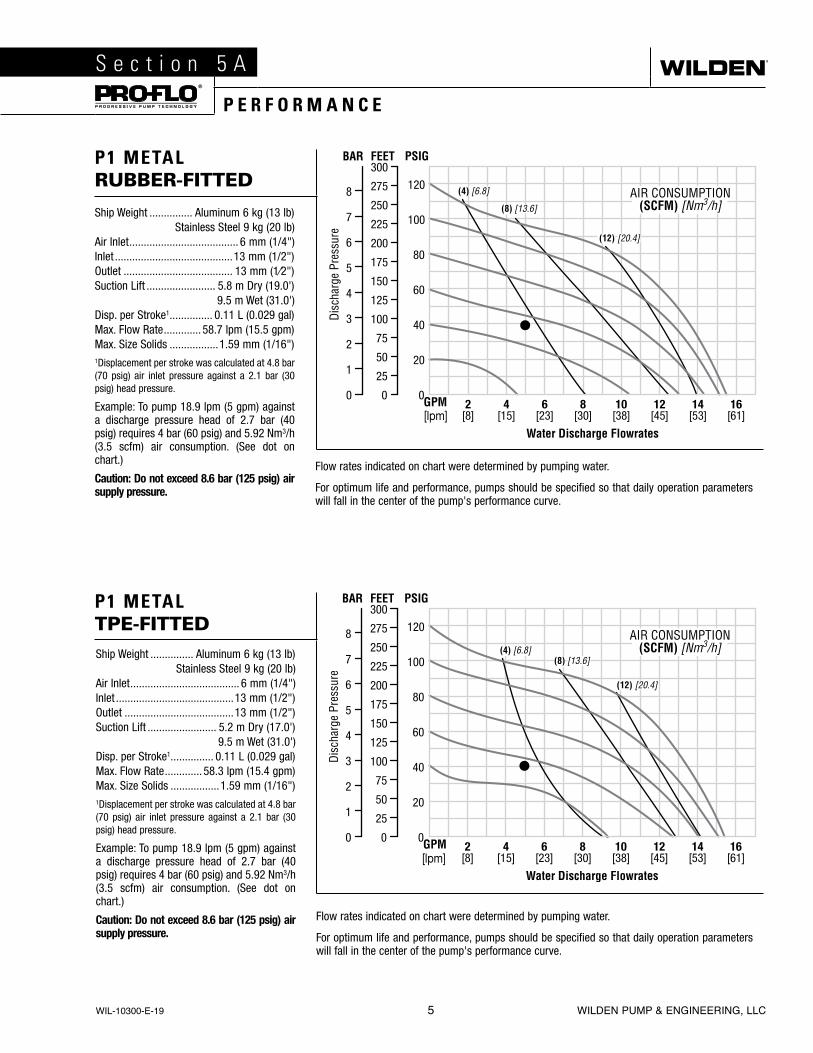
P1 METAL RUBBER-FITTED
Ship Weight ............... Aluminum 6 kg (13 lb)Stainless Steel 9 kg (20 lb)
Air Inlet ...................................... 6 mm (1/4")Inlet .........................................13 mm (1/2")Outlet ...................................... 13 mm (1⁄2")Suction Lift ........................ 5.8 m Dry (19.0')
9.5 m Wet (31.0')Disp. per Stroke1 ............... 0.11 L (0.029 gal)Max. Flow Rate ............. 58.7 lpm (15.5 gpm)Max. Size Solids .................1.59 mm (1/16")1Displacement per stroke was calculated at 4.8 bar (70 psig) air inlet pressure against a 2.1 bar (30 psig) head pressure.
Example: To pump 18.9 lpm (5 gpm) against a discharge pressure head of 2.7 bar (40 psig) requires 4 bar (60 psig) and 5.92 Nm3/h (3.5 scfm) air consumption. (See dot on chart.)
Caution: Do not exceed 8.6 bar (125 psig) air supply pressure.
Ship Weight ............... Aluminum 6 kg (13 lb)Stainless Steel 9 kg (20 lb)
Air Inlet ...................................... 6 mm (1/4")Inlet .........................................13 mm (1/2")Outlet ......................................13 mm (1/2")Suction Lift ........................ 5.2 m Dry (17.0')
9.5 m Wet (31.0')Disp. per Stroke1 ............... 0.11 L (0.029 gal)Max. Flow Rate ............. 58.3 lpm (15.4 gpm)Max. Size Solids .................1.59 mm (1/16")1Displacement per stroke was calculated at 4.8 bar (70 psig) air inlet pressure against a 2.1 bar (30 psig) head pressure.
Example: To pump 18.9 lpm (5 gpm) against a discharge pressure head of 2.7 bar (40 psig) requires 4 bar (60 psig) and 5.92 Nm3/h (3.5 scfm) air consumption. (See dot on chart.)
Caution: Do not exceed 8.6 bar (125 psig) air supply pressure.
(16) [27.2]
WIL-10300-E-19 5 WILDEN PUMP & ENGINEERING, LLC
Flow rates indicated on chart were determined by pumping water.
For optimum life and performance, pumps should be specified so that daily operation parameters will fall in the center of the pump's performance curve.
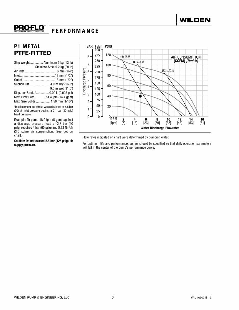
P1 METAL PTFE-FITTED
Ship Weight ............... Aluminum 6 kg (13 lb)Stainless Steel 9.2 kg (20 lb)
Air Inlet ...................................... 6 mm (1/4")Inlet .........................................13 mm (1/2")Outlet ......................................13 mm (1/2")Suction Lift ........................ 4.9 m Dry (16.0')
9.5 m Wet (31.0')Disp. per Stroke1 ............... 0.09 L (0.025 gal)Max. Flow Rate ............. 54.4 lpm (14.4 gpm)Max. Size Solids .................1.59 mm (1/16")1Displacement per stroke was calculated at 4.8 bar (70) air inlet pressure against a 2.1 bar (30 psig) head pressure.
Example: To pump 18.9 lpm (5 gpm) against a discharge pressure head of 2.7 bar (40 psig) requires 4 bar (60 psig) and 5.92 Nm3/h (3.5 scfm) air consumption. (See dot on chart.)
Caution: Do not exceed 8.6 bar (125 psig) air supply pressure.
(16) [27.2]
P E R F O R M A N C E
WILDEN PUMP & ENGINEERING, LLC 6 WIL-10300-E-19
P1 METAL
S e c t i o n 5 B
S U C T I O N - L I F T C U R V E S
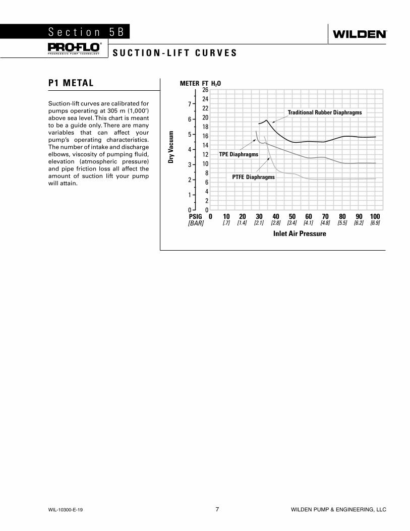
Suction-lift curves are calibrated for pumps operating at 305 m (1,000’) above sea level. This chart is meant to be a guide only. There are many variables that can affect your pump’s operating characteristics. The number of intake and discharge elbows, viscosity of pumping fluid, elevation (atmospheric pressure) and pipe friction loss all affect the amount of suction lift your pump will attain.
WIL-10300-E-19 7 WILDEN PUMP & ENGINEERING, LLC

Wilden pumps are designed to meet the performance requirements of even the most demanding pumping applications. They have been designed and manufactured to the highest standards and are available in a variety of liquid path materials to meet your chemical resistance needs. Refer to the performance section of this manual for an in-depth analysis of the performance characteristics of your pump. Wilden offers the widest variety of elastomer options in the industry to satisfy temperature, chemical compatibility, abrasion resistance and flex concerns.
The suction pipe size should be at least the equivalent or larger than the diameter size of the suction inlet on your Wilden pump. The suction hose must be non-collapsible, reinforced type as these pumps are capable of pulling a high vacuum. Discharge piping should also be the equivalent or larger than the diameter of the pump discharge which will help reduce friction losses. It is critical that all fittings and connections are airtight or a reduction or loss of pump suction capability will result.
INSTALLATION: Months of careful planning, study, and selection efforts can result in unsatisfactory pump performance if installation details are left to chance.
Premature failure and long-term dissatisfaction can be avoided if reasonable care is exercised throughout the installation process.
LOCATION: Noise, safety, and other logistical factors usually dictate where equipment will be situated on the production floor. Multiple installations with conflicting requirements can result in congestion of utility areas, leaving few choices for additional pumps.
Within the framework of these and other existing conditions, every pump should be located in such a way that the following key factors are balanced against each other to maximum advantage.
ACCESS: First of all, the location should be accessible. If it’s easy to reach the pump, maintenance personnel will have an easier time carrying out routine inspections and adjustments. Should major repairs become necessary, ease of access can play a key role in speeding the repair process and reducing total downtime.
AIR SUPPLY: Every pump location should have an air line large enough to supply the volume of air necessary to achieve the desired pumping rate.
For best results, the pumps should use a 5µ (micron) air filter, needle valve and regulator. The use of an air filter before the pump will ensure that the majority of any pipeline contaminants will be eliminated.
SOLENOID OPERATION: When operation is controlled by a solenoid valve in the air line, three-way valves should be used. This valve allows trapped air between the valve and the pump to bleed off which improves pump performance. Pumping volume can be estimated by counting the number of strokes per minute and then multiplying the figure by the displacement per stroke.
MUFFLER: Sound levels are reduced below OSHA specifications using the standard Wilden muffler. Other mufflers can be used to further reduce sound levels, but they usually reduce pump performance.
ELEVATION: Selecting a site that is well within the pump’s dynamic lift capability will assure that loss-of-prime issues will be eliminated. In addition, pump efficiency can be adversely affected if proper attention is not given to site location.
PIPING: Final determination of the pump site should not be made until the piping challenges of each possible location have been evaluated. The impact of current and future installations should be considered ahead of time to make sure that inadvertent restrictions are not created for any remaining sites.
For UL-listed pumps, all installation must conform with NFPA 30, NFPA 30A, and other applicable codes. All pipe connections are to be made using UL-classified gasoline-resistant pipe compound. Exhaust port is to be connected to pipe or tubing to be routed outdoors or other location determined to be equivalent.
The best choice possible will be a site involving the shortest and straightest hook-up of suction and discharge piping. Unnecessary elbows, bends, and fittings should be avoided. Pipe sizes should be selected to keep friction losses within practical limits. All piping should be supported independently of the pump. In addition, the piping should be aligned to avoid placing stress on the pump fittings.
Flexible hose can be installed to aid in absorbing the forces created by the natural reciprocating action of the pump. If the pump is to be bolted down to a solid location, a mounting pad placed between the pump and the foundation will assist in minimizing pump vibration. Flexible connections between the pump and rigid piping will also assist in minimizing pump vibration. If quick-closing valves are installed at any point in the discharge system, or if pulsation within a system becomes a problem, a surge suppressor (SD Equalizer®) should be installed to protect the pump, piping and gauges from surges and water hammer.
If the pump is to be used in a self-priming application, make sure that all connections are airtight and that the suction lift is within the model’s ability. NOTE: Materials of construction and elastomer material have an effect on suction lift parameters. Please refer to the performance section for specifics.
When pumps are installed in applications involving flooded suction or suction head pressures, a gate valve should be installed in the suction line to permit closing of the line for pump service.
Pumps in service with a positive suction head are most efficient when inlet pressure is limited to 0.5–0.7 bar (7–10 psig). Premature diaphragm failure may occur if positive suction is 0.7 bar (10 psig) and higher.
NOTE: Pro-Flo® and Accu-Flo™ pumps do not have a single-point exhaust option and are not submersible.
ALL WILDEN PUMPS ARE CAPABLE OF PASSING SOLIDS. A STRAINER SHOULD BE USED ON THE PUMP INTAKE TO ENSURE THAT THE PUMP'S RATED SOLIDS CAPACITY IS NOT EXCEEDED.
CAUTION: DO NOT EXCEED 8.6 BAR (125 PSIG) AIR SUPPLY PRESSURE.
CAUTION: FOR UL-LISTED PUMPS, DO NOT EXCEED 3.4 BAR (50 PSIG) AIR SUPPLY PRESSURE.
S e c t i o n 6
S U G G E S T E D I N S T A L L A T I O N
WILDEN PUMP & ENGINEERING, LLC 8 WIL-10300-E-19

S U G G E S T E D I N S T A L L A T I O N
NOTE: In the event of a power failure, the shut-off valve should be closed, if the restarting of the pump is not desirable once power is regained.
AIR-OPERATED PUMPS: To stop the pump from operating in an emergency situation, simply close the shut-off valve (user-supplied) installed in the air supply line. A properly functioning valve will stop the air supply to the pump, therefore st pping output. This shut-off valve should be located far enough away from the pumping equipment such that it can be reached safely in an emergency situation.
AIR SHUT-OFF VALVE
FOOTPAD
COMBINATIONFILTER & REGULATOR
SUCTION
MUFFLER
FLEXIBLECONNECTION
FLEXIBLECONNECTION
GAUGE(OPTIONAL)
EQUALIZERSURGE DAMPENER
(OPTIONAL)
SHUT-OFFVALVE
DISCHARGE
WIL-10300-E-19 9 WILDEN PUMP & ENGINEERING, LLC

S e c t i o n 7
P U M P D I S A S S E M B L YOPERATION: P1 pumps are pre-lubricated, and do not require in-line lubrication. Additional lubrication will not damage the pump, however if the pump is heavily lubricated by an external source, the pump’s internal lubrication may be washed away. If the pump is then moved to a non-lubricated location, it may need to be disassembled and re-lubricated as described in the REASSEMBLY/DISASSEMBLY INSTRUCTIONS.
Pump discharge rate can be controlled by limiting the volume and/or pressure of the air supply to the pump. A regulator is used to control air pressure while a needle valve is used to control volume. Pump discharge rate can also be controlled by throttling the pump discharge by partially closing a valve in the discharge line of the pump. This action increases friction loss which reduces flow rate. (See Section 5.) This is useful when the need exists to control the pump from a remote location. When the pump discharge pressure equals or exceeds the air supply pressure, the pump will stop; no bypass or pressure relief valve is needed, and pump damage will not occur. The pump has reached a “deadhead” situation and can be restarted by reducing the fluid discharge pressure or increasing the air inlet pressure.
The P1 pumps run solely on compressed air and do not generate heat, therefore your process fluid temperature will not be affected.
NOTE: Canadian Standards Association (CSA)-configured pumps run solely on gas and do not generate heat.
MAINTENANCE AND INSPECTIONS: Since each application is unique, maintenance schedules may be different for every pump. Frequency of use, line pressure, viscosity and abrasiveness of process fluid all affect the parts life of a Wilden pump. Periodic inspections have been found to offer the best means for preventing unscheduled pump downtime. Personnel familiar with the pump’s construction and service should be informed of any abnormalities that are detected during operation.
RECORDS: When service is required, a record should be made of all necessary repairs and replacements. Over a period of time, such records can become a valuable tool for predicting and preventing future maintenance problems and unscheduled downtime. In addition, accurate records make it possible to identify pumps that are poorly suited to their applications.
Pump will not run or runs slowly.
1. Remove plug from pilot spool exhaust.
2. Ensure that the air inlet pressure is at least 0.3 bar (5 psig) above startup pressure and that the differential pressure (the difference between air inlet and liquid discharge pressures) is not less than 0.7 bar (10 psig).
3. Check air inlet filter for debris (see SUGGESTED INSTALLATION).
4. Check for extreme air leakage (blow by) which would indicate worn seals/bores in the air valve, pilot spool and main shaft.
5. Disassemble pump and check for obstructions in the air passageways or objects which would obstruct the movement of internal parts.
6. Check for sticking ball check valves. If material being pumped is not compatible with pump elastomers, swelling may occur. Replace ball check valves and seals with proper elastomers. Also, as the check valve balls wear out, they become smaller and can become stuck in the seats. In this case, replace balls and seats.
7. Check for broken inner piston which will cause the air valve spool to be unable to shift.
Pump runs but little or no product flows.
1. Check for pump cavitation; slow pump speed down to allow thick material to flow into liquid chambers.
2. Verify that vacuum required to lift liquid is not greater than the vapor pressure of the material being pumped (cavitation).
3. Check for sticking ball check valves. If material being pumped is not compatible with pump elastomers, swelling may occur. Replace ball check valves and seats with proper elastomers. Also, as the check valve balls wear out, they become smaller and can become stuck in the seats. In this case, replace balls and seats.
Pump air valve freezes.
1. Check for excessive moisture in compressed air. Either install a dryer or hot air generator for compressed air. Alternatively, a coalescing filter may be used to remove the water from the compressed air in some applications.
Air bubbles in pump discharge.
1. Check for ruptured diaphragm.
2. Check tightness of outer pistons (refer to Section 7).
3. Check tightness of fasteners and integrity of O-rings and seals, especially at intake manifold.
4. Ensure pipe connections are airtight.
Product comes out air exhaust.
1. Check for diaphragm rupture.
2. Check tightness of outer pistons to shaft.
S U G G E S T E D O P E R A T I O N & M A I N T E N A N C E
T R O U B L E S H O O T I N G
WILDEN PUMP & ENGINEERING, LLC 10 WIL-10300-E-19

CAUTION: Before any maintenance or repair is attempted, the compressed air line to the pump should be disconnected and all air pressure allowed to bleed from the pump. Disconnect all intake, discharge and air lines. Drain the pump by turning it upside down and allowing any fluid to flow into a suitable container. Be aware of any hazardous effects of contact with your process fluid.
NOTE: The model photographed for these instructions is a PX version and incorporates rubber diaphragms, balls and seats.
S e c t i o n 7
P U M P D I S A S S E M B L Y
Step 2
Using a 7/16” box wrench, remove the nuts that connect the inlet and discharge manifolds to the center section assembly.
Step 3
Next, remove the discharge manifold from the pump.
Step 1
Prior to disassembly, alignment marks should be placed on the liquid chambers and air chamber to assist with proper alignment during reassembly.
WIL-10300-E-19 11 WILDEN PUMP & ENGINEERING, LLC
TOOLS REQUIRED:
• 3/8" Box Wrench• 7/16" Wrench• Adjustable Wrench• Vise equipped with soft
jaws (such as plywood, plastic or other suitable material)

P U M P D I S A S S E M B L Y
Step 7
Using a 3/8” wrench, remove the small clamp band that connects the manifold elbows to the tee section.
Step 8
Remove the tee section o-rings and inspect for signs of wear and/or chemical attack. Replace, if necessary.
Step 9
Using a 7/16” box end wrench, remove the large clamp bands. With the clamp bands removed, lift the liquid chamber away from the center section.
Step 4
Remove the discharge valve ball, valve seat and valve seat O-ring and inspect for signs of wear and replace, if necessary.
Step 5
Now the center section assembly can be removed from the inlet manifold.
Step 6
Remove the inlet valve ball, valve seat and valve seat O-ring and inspect for signs of wear and/or chemical attack. Replace, if necessary.
WILDEN PUMP & ENGINEERING, LLC 12 WIL-10300-E-19
P U M P D I S A S S E M B L Y
Step 11B
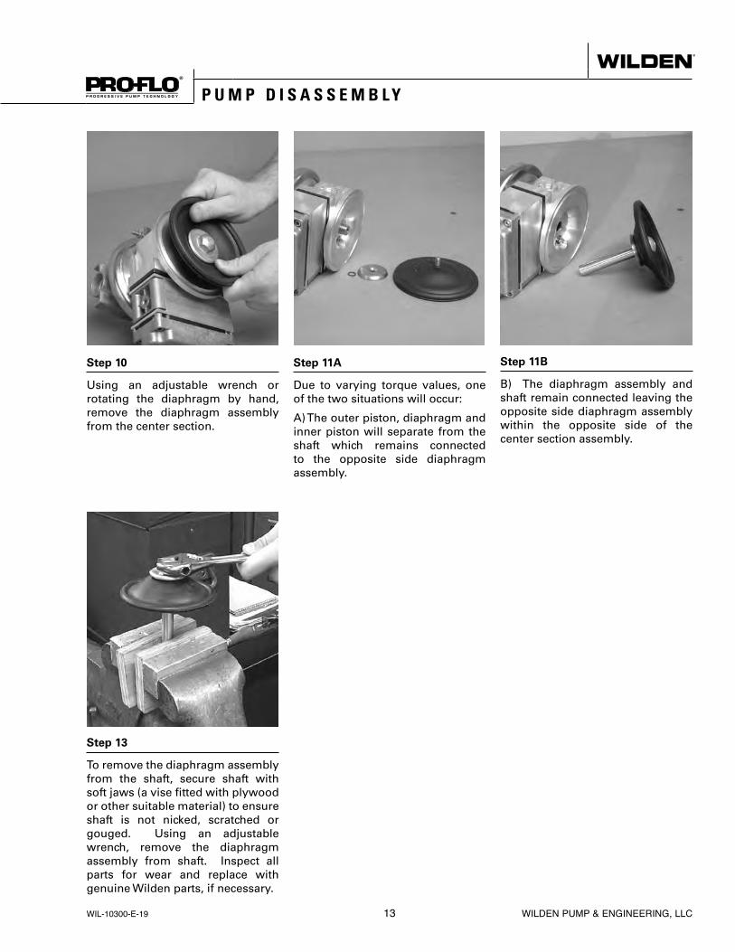
B) The diaphragm assembly and shaft remain connected leaving the opposite side diaphragm assembly within the opposite side of the center section assembly.
Step 10
Using an adjustable wrench or rotating the diaphragm by hand, remove the diaphragm assembly from the center section.
Step 11A
Due to varying torque values, one of the two situations will occur:
A) The outer piston, diaphragm and inner piston will separate from the shaft which remains connected to the opposite side diaphragm assembly.
Step 13
To remove the diaphragm assembly from the shaft, secure shaft with soft jaws (a vise fitted with plywood or other suitable material) to ensure shaft is not nicked, scratched or gouged. Using an adjustable wrench, remove the diaphragm assembly from shaft. Inspect all parts for wear and replace with genuine Wilden parts, if necessary.
WIL-10300-E-19 13 WILDEN PUMP & ENGINEERING, LLC

CAUTION: Before any maintenance or repair is attempted, the compressed air line to the pump should be disconnected and all air pressure allowed to bleed from the pump. Disconnect all intake, discharge and air lines. Drain the pump by turning it upside down and allowing any fluid to flow into a suitable container. Be aware of hazardous effects of contact with your process fluid.
TOOLS REQUIRED:
• 3/16" Hex-Head Wrench• 7/32" Hex-Head Wrench• Snap-Ring Pliers• O-Ring Pick
A I R V A L V E / C E N T E R S E C T I O N D I S A S S E M B L Y
Step 1
Using a 3/16” hex-head wrench, loosen the air valve bolts.
Step 2
Remove the air valve and muffler plate from the center section.
Step 3
Remove the air valve gasket and inspet for nicks, gouges and chemical attack. Replace if necessary with genuine Wilden parts. NOTE: When installing the air valve gasket onto the center section assembly, position gasket with the grooved side facing away from the center section.
WILDEN PUMP & ENGINEERING, LLC 14 WIL-10300-E-19
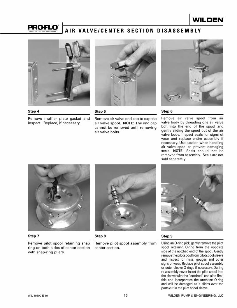
A I R V A L V E / C E N T E R S E C T I O N D I S A S S E M B L Y
Step 7
Remove pilot spool retaining snap ring on both sides of center section with snap-ring pliers.
Step 8
Remove pilot spool assembly from center section.
Step 9
Using an O-ring pick, gently remove the pilot spool retaining O-ring from the opposite side of the notched end of the spool. Gently remove the pilot spool from pilot spool sleeve and inspect for nicks, gouges and other signs of wear. Replace pilot spool assembly or outer sleeve O-rings if necessary. During re-assembly never insert the pilot spool into the sleeve with the “notched” end side first, this end incorporates the urethane O-ring and will be damaged as it slides over the ports cut in the pilot spool sleeve.
Step 4
Remove muffler plate gasket and inspect. Replace, if necessary.
Step 5
Remove air valve end cap to expose air valve spool. NOTE: The end cap cannot be removed until removing air valve bolts.
Step 6
Remove air valve spool from air valve body by threading one air valve bolt into the end of the spool and gently sliding the spool out of the air valve body. Inspect seals for signs of wear and replace entire assembly if necessary. Use caution when handling air valve spool to prevent damaging seals. NOTE: Seals should not be removed from assembly. Seals are not sold separately.
WIL-10300-E-19 15 WILDEN PUMP & ENGINEERING, LLC

A I R V A L V E / C E N T E R S E C T I O N D I S A S S E M B L Y
Step 10
Check center section shaft seals for signs of wear. If necessary, remove the shaft seals with an O-ring pick and replace.
WILDEN PUMP & ENGINEERING, LLC 16 WIL-10300-E-19

REASSEMBLY:Upon performing applicable maintenance to the air dis-tribution system, the pump can now be reassembled. Please refer to the disassembly instructions for photos and parts placement. To reassemble the pump, follow the disassembly instructions in reverse order. The air distribution system needs to be assembled first, then the diaphragms and finally the wetted path. Please find the applicable torque specifications on this page. The follow-ing tips will assist in the assembly process.
• Clean the inside of the center section shaft bore to ensure no damage is done to new seals.
• Stainless bolts should be lubed to reduce the possibil-ity of seizing during tightening.
• Level the water chamber side of the intake/discharge manifold to ensure a proper sealing surface. This is most easily accomplished by placing them on a flat surface prior to tightening their clamp bands to the desired torque (see below for Torque Specifications).
• Be sure to tighten outer pistons simultaneously on PTFE-fitted pumps to ensure proper torque values.
• Ensure proper mating of liquid chambers to manifolds prior to tightening vertical bolts. Overhang should be equal on both sides.
• Apply a small amount of Loctite 242 to the shaft inter-val threads before the diaphragm assembly.
• Concave side of disc spring in diaphragm assembly faces toward shaft.
R E A S S E M B L Y H I N T & T I P S
PRO-FLO® MAXIMUM TORQUE SPECIFICATIONSDescription of Part Maximum Torque
Air Valve, Pro-Flo® 3.1 N•m (27 in-lb)
Outer Piston 14.1 N•m (125 in-lb)
Small Clamp Band 1.7 N•m (15 in-lb)
Large Clamp Band (Rubber/TPE-Fitted) 9.0 N•m (80 in-lb)
Large Clamp Band (PTFE-Fitted) 13.6 N•m (120 in-lb)
Vertical Bolts 14.1 N•m (125 in-lb)
WIL-10300-E-19 17 WILDEN PUMP & ENGINEERING, LLC

P1 METAL R U B B E R / T P E - F I T T E D E X P L O D E D V I E W
S e c t i o n 8
E X P L O D E D V I E W & P A R T S L I S T I N G
WILDEN PUMP & ENGINEERING, LLC 18 WIL-10300-E-19
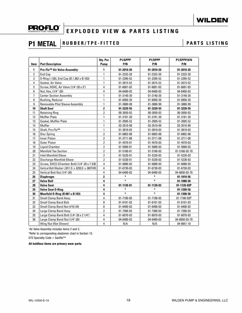
Item Part DescriptionQty. PerPump
P1/APPPP/N
P1/SPPPP/N
P1/SPPP/070P/N
1 Pro-Flo™ Air Valve Assembly1 1 01-2010-20 01-2010-20 01-2010-202 End Cap 1 01-2332-20 01-2332-20 01-2332-203 O-Ring (-126), End Cap (Ø.1.362 x Ø.103) 1 01-2395-52 01-2395-52 01-2395-524 Gasket, Air Valve 1 01-2615-52 01-2615-52 01-2615-525 Screw, HSHC, Air Valve (1/4"-20 x 3") 4 01-6001-03 01-6001-03 01-6001-036 Nut, Hex, (1/4”-20) 4 04-6400-03 04-6400-03 04-6400-037 Center Section Assembly 1 01-3140-20 01-3140-20 01-3140-208 Bushing, Reducer 1 01-6950-20 01-6950-20 01-6950-209 Removable Pilot Sleeve Assembly 1 01-3880-99 01-3880-99 01-3880-9910 Shaft Seal 2 01-3220-55 01-3220-55 01-3220-5511 Retaining Ring 2 00-2650-03 00-2650-03 00-2650-0312 Muffler Plate 1 01-3181-20 01-3181-20 01-3181-2013 Gasket, Muffler Plate 1 01-3505-52 01-3505-52 01-3505-5214 Muffler 1 02-3510-99 02-3510-99 02-3510-9915 Shaft, Pro-Flo™ 1 01-3810-03 01-3810-03 01-3810-0316 Disc Spring 2 01-6802-08 01-6802-08 01-6802-0817 Inner Piston 2 01-3711-08 01-3711-08 01-3711-0818 Outer Piston 2 01-4570-01 01-4570-03 01-4570-0319 Liquid Chamber 2 01-5000-01 01-5000-03 01-5000-0320 Manifold Tee Section 2 01-5160-01 01-5160-03 01-5160-03-7021 Inlet Manifold Elbow 2 01-5220-01 01-5220-03 01-5220-0322 Discharge Manifold Elbow 2 01-5230-01 01-5230-03 01-5230-0323 Screw, SHCS (Chamber Bolt) (1/4"-20 x 7 3/8) 4 01-6080-03 01-6080-03 01-6080-0324 Vertical Bolt Washer (.2811.D. x .6250.D. x .065THR) 4 01-6730-03 01-6730-03 01-6730-0325 Vertical Bolt Nut (1/4"-20) 4 04-6400-03 04-6400-03 04-6650-03-7026 Diaphragm 2 * * 01-1010-5627 Valve Ball 4 * * 01-1080-5628 Valve Seat 4 01-1120-01 01-1120-03 01-1120-03P29 Valve Seat O-Ring 4 * * 01-1200-5630 Manifold O-Ring (Ø.987 x Ø.103) 4 * * 01-1300-5631 Small Clamp Band Assy. 4 01-7100-03 01-7100-03 01-7100-03P32 Small Clamp Band Bolt 8 01-6101-03 01-6101-03 01-6101-0333 Small Clamp Band Nut (#10-24) 8 01-6400-03 01-6400-03 01-6400-0334 Large Clamp Band Assy. 2 01-7300-03 01-7300-03 01-7300-0335 Large Clamp Band Bolt (1/4"-20 x 2 1/4") 4 01-6070-03 01-6070-03 01-6070-0336 Large Clamp Band Nut (1/4"-20) 4 04-6400-03 04-6400-03 04-6650-03-70
Wing Nut (Not Shown) 4 N/A N/A 04-6651-101Air Valve Assembly includes items 2 and 3.*Refer to corresponding elastomer chart in Section 10.070 Specialty Code = SanifloFDA
All boldface items are primary wear parts.
E X P L O D E D V I E W & P A R T S L I S T I N G
P1 METAL R U B B E R / T P E - F I T T E D P A R T S L I S T I N G
WIL-10300-E-19 19 WILDEN PUMP & ENGINEERING, LLC

P1 METAL P T F E - F I T T E D E X P L O D E D V I E W
E X P L O D E D V I E W & P A R T S L I S T I N G
WILDEN PUMP & ENGINEERING, LLC 20 WIL-10300-E-19

Item Part DescriptionQty Per.Pump
P1/APPPP/N
P1/SPPPP/N
P1/SPPP/070P/N
1 Pro-Flo™ Air Valve Assembly1 1 01-2010-20 01-2010-20 01-2010-202 End Cap 1 01-2332-20 01-2332-20 01-2332-203 O-Ring (-126) (Ø.1.362 x Ø.103), End Cap 1 01-2395-52 01-2395-52 01-2395-524 Gasket, Air Valve 1 01-2615-52 01-2615-52 01-2615-525 Screw, HSHC, Air Valve (1⁄4-20 x 3") 4 01-6001-03 01-6001-03 01-6001-036 Nut, Hex, (1/4”-20) 4 04-6400-03 04-6400-03 04-6400-037 Center Section Assembly 1 01-3140-20 01-3140-20 01-3140-208 Bushing, Reducer 1 01-6950-20 01-6950-20 01-6950-209 Removable Pilot Sleeve Assembly 1 01-3880-99 01-3880-99 01-3880-99
10 Shaft Seal 2 01-3220-55 01-3220-55 01-3220-5511 Retaining Ring 2 00-2650-03 00-2650-03 00-2650-0312 Muffler Plate 1 01-3181-20 01-3181-20 01-3181-2013 Gasket, Muffler Plate 1 01-3505-52 01-3505-52 01-3505-5214 Muffler 1 02-3510-99 02-3510-99 01-3510-9915 Shaft, Pro-Flo™ 1 01-3810-03 01-3810-03 01-3810-0316 Disc Spring (Belleville Washer) 2 01-6802-08 01-6802-08 01-6802-0817 Inner Piston 2 01-3711-08 01-3711-08 01-3711-0818 Outer Piston 2 01-4570-01 01-4570-03 01-4570-0319 Liquid Chamber 2 01-5000-01 01-5000-03 01-5000-0320 Manifold Tee Section 2 01-5160-01 01-5160-03 01-5160-03-7021 Inlet Manifold Elbow 2 01-5220-01 01-5220-03 01-5220-0322 Discharge Manifold Elbow 2 01-5230-01 01-5230-03 01-5230-0323 Screw, SHCS (Chamber Bolt) (1/4"-20 x 7 3/8) 4 01-6080-03 01-6080-03 01-6080-0324 Vertical Bolt Washer (.2811.D. x .6250.D. x .065THR) 4 01-6730-03 01-6730-03 01-6730-0325 Vertical Bolt Nut (1/4"-20) 4 04-6400-03 04-6400-03 04-6650-03-7026 PTFE Primary Diaphragm 2 01-1010-55 01-1010-55 01-1010-5527 Neoprene Backup Diaphragm 2 01-1060-51 01-1060-51 01-1060-5128 Valve Ball 4 01-1080-55 01-1080-55 01-1080-5529 Valve Seat 4 01-1120-01 01-1120-03 01-1120-03P30 Valve Seat (-119) O-Ring (Ø.924 x Ø.103) 4 01-1200-55 01-1200-55 01-1200-5531 Manifold (-120) O-Ring (Ø.987 x Ø.103) 4 01-1300-55 01-1300-55 01-1300-5532 Small Clamp Band Assy. 4 01-7100-03 01-7100-03 01-7100-0333 Small Clamp Band Bolt (#10-24 x 1") 8 01-6101-03 01-6101-03 01-6101-0334 Small Clamp Band Nut (#10-24) 8 01-6400-03 01-6400-03 01-6400-0335 Large Clamp Band Assy. 2 01-7300-03 01-7300-03 01-7300-0336 Large Clamp Band Bolt (1/4"-20 x 2 1/4") 4 01-6070-03 01-6070-03 01-6070-0337 Large Clamp Band Nut (1/4"-20) 4 04-6400-03 04-6400-03 04-6650-03-70
Wing Nut 4 N/A N/A 04-6651-101Air Valve Assembly includes items 2 and 3.*Refer to corresponding elastomer chart in Section 10.070 Specialty Code = SanifloFDA
All boldface items are primary wear parts.
E X P L O D E D V I E W & P A R T S L I S T I N G
P1 METAL P T F E - F I T T E D P A R T S L I S T I N G
WIL-10300-E-19 21 WILDEN PUMP & ENGINEERING, LLC

P1 METAL SANIFLO™ 1 9 3 5 / 2 0 0 4 / E C E X P L O D E D V I E W
E X P L O D E D V I E W & P A R T S L I S T I N G
WILDEN PUMP & ENGINEERING, LLC 22 WIL-10300-E-19
PTFE
PTFE IPDLW0093, Rev. A

E X P L O D E D V I E W & P A R T S L I S T I N G
P1 METAL SANIFLO™ 1 9 3 5 / 2 0 0 4 / E C P A R T S L I S T I N G
Item Description Qty.P1/SSLLL/
1935/2004/ECP/N
P1/SSPPP/ 1935/2004/EC
P/N
AIR DISTRIBUTION COMPONENTS1 Air Valve Assembly, Pro-Flo 1 1 01-2010-13 01-2010-202 End Cap 1 01-2332-13 01-2332-203 O-Ring (-126), End Cap (Ø1.362” x Ø.103”) 1 01-2395-52 01-2395-524 Gasket, Air Valve, Pro-Flo™ 1 01-2615-52 01-2615-525 Gasket, Muffler Plate, Pro-Flo™ 1 01-3505-52 01-3505-526 Muffler Plate, Pro-Flo™ 1 01-3181-13 01-3181-207 Screw, SHC, Air Valve (1/4”-20 x 3”) 4 01-6001-03 01-6001-038 Hex Nut, (1/4”-20) 4 04-6400-03 04-6400-039 Muffler, 1/2” MNPT 1 02-3510-99 02-3510-99
10 Center Section Assembly, Pro-Flo™ 2 1 01-3140-13 01-3140-2011 Assembly, Pilot Sleeve 1 01-3880-99 01-3880-9912 O-Ring (-009), Pilot Spool Retaining (Ø.208” x Ø.070”) 2 04-2650-49-700 04-2650-49-70013 Seal, Shaft 2 01-3220-55 01-3220-5514 Bushing, Reducer, 1/2” MNPT to 1/4” FNPT 1 01-6950-20 01-6950-2015 Ring, Retaining 2 00-2650-03 00-2650-03
WETTED PATH COMPONENTS16 Chamber, Liquid 2 01-5000-03P 01-5000-03P17 Manifold, T-Section 2 01-5160-03-70P 01-5160-03-70P18 Elbow, Inlet Manifold 2 01-5220-03P 01-5220-03P19 Elbow, Discharge Manifold 2 01-5230-03P 01-5230-03P20 O-Ring, Manifold (-120), (Ø.987 x Ø.103) 4 * *21 Screw, SHCS, (Chamber Bolt) (1/4”-20 x 7-1/2”) 4 01-6080-03 01-6080-0322 Washer, Flat (Ø.281” x Ø.625” x .065”) 4 01-6730-03 01-6730-0323 Large Clamp Band Assembly 4 01-7300-03 01-7300-0324 RHSN Bolt, Large Clamp Band (1/4”-20 x 2-1/4”) 4 01-6070-03 01-6070-0325 Wing Nut, (1/4”-20) 8 04-6651-10 04-6651-1026 Small Clamp Band Assembly 8 01-7100-03-70 01-7100-03-7027 HHC Screw, Small Clamp Band (#10-24 x 1”) 8 01-6101-03 01-6101-0328 HEX Nut, Small Clamp Band (#10-24) 8 01-6400-03 01-6400-03
VALVE BALLS/VALVE SEATS/VALVE O-RINGS29 Ball, Valve, Pkg 4 1 * *30 Seat, Valve 4 01-1120-03E 01-1120-03E31 O-Ring (-119),Valve Seat (Ø.924 x Ø.139), Pkg 4 1 * *
FULL STROKE RUBBER/TPE/PTFE COMPONENTS32 Shaft 1 01-3810-03 01-3810-0333 Stud, Shaft (5/16”-18 x 1-3/8”) 2 01-6150-03 01-6150-0334 Spring, Disk (Ø.331” x Ø.512”) 2 01-6802-08 01-6802-0835 Piston, Inner 2 01-3711-08 01-3711-0836 Diaphragm, Primary, Pkg 2 1 * *37 Diaphragm, Back-Up, Pkg 2 1 * *38 Piston, Outer 2 01-4570-03E 01-4570-03E
REDUCE STROKE PTFE/IPD COMPONENTS32 Shaft 1 01-3810-03 01-3810-0334 Spring, Disk (Ø.331” x Ø.512”) 2 01-6802-08 01-6802-0835 Piston, Inner 2 01-3711-08 01-3711-0836 Diaphragm, Primary, Pkg 2 1 * *37 Diaphragm, Back-Up, Pkg 2 1 * *
LW0082 Rev. B1 Air Valve Assembly includes items 2 and 3.2 Center Section Assembly includes items 13 and 14.All boldface items are primary wear parts.
WIL-10300-E-19 23 WILDEN PUMP & ENGINEERING, LLC

P1 Metal
MATERIAL DIAPHRAGMS VALVE BALL VALVE SEAT O-RINGS MANIFOLD O-RINGS
Polyurethane 01-1010-50 01-1080-50 01-1200-50 01-1300-50
Buna-N 01-1010-52 01-1080-52 00-1260-52 01-1300-52
FKM 01-1010-53 01-1080-53 N/A N/A
Wil-Flex™ 01-1010-58 01-1080-58 00-1260-58 00-1260-58
Saniflex™ 01-1010-56 01-1080-56 01-1200-56 01-1300-56
PTFE** 01-1010-55 01-1080-55 01-1200-55 01-1300-55
EPDM 01-1010-54 01-1080-54 00-1260-54 01-1300-54
S e c t i o n 9
E L A S T O M E R O P T I O N S
**NOTE: An integral piston PTFE diaphragm is also available. To order this diaphragm, use part number 01-1030-55. When using this diaphragm, no outer pistons are needed. The outer piston is integrated into the diaphragm design.
P1 Metal Saniflo™ 1935/2004/EC
MATERIAL DIAPHRAGMS
REDUCED-STROKE BACKUP
DIAPHRAGMS VALVE BALLSVALVE SEATS
O-RINGSMANIFOLD O-RINGS
FDA EPDM N/A 01-1060-54E N/A N/A N/ASaniflex™ 01-1010-56E 01-1060-56E 01-1080-56E 01-1200-56E 01-1300-56E
PTFE 01-1010-55E N/A 01-1080-55E 01-1200-55E 01-1300-55ELWOO82, Rev. B
WILDEN PUMP & ENGINEERING, LLC 24 WIL-10300-E-19

DECLARATION OF CONFORMITYSTATEMENT OF COMPLIANCE TO REGULATIONS (EC) NO 1935/2004
ON MATERIALS AND ARTICLES INTEDNDED TO COME INTO CONTACT WITH FOOD(as per Article 16 of EGULATION (EC) No 1935/2004)
Wilden Pump & Engineering, LLC, 22069 Van Buren Street, Grand Terrace, CA 92313-5607 USA,certifies as the manufacturer that the Air-Operated Double Diaphragm pumps listed below comply with the European Community Regulation 1935/2004/(EC) for Food Contact Materials.
§ 25 mm (1”) Saniflo Hygienic™ HS Metal Pump:(PX,XPX)2 /(SS,SZ)(SSS,NNN)/(FBS,FES,FSL,FSS,LEL,TEU,TSS,TSU)/(FB,FE,FS,TF)/(FB,FE,FV,TF)/(0770-0789)E
§ 38 mm – 76 mm (1-½”-3”) Pro-Flo X Saniflo Hygienic™ HS Metal Pump: (PX,XPX)(4,8,15)/(SS,SZ)(SSS,NNN)/(BNU,EPU,FBS,FES,FSL,FSS,LEL,TEU,TSS,TSU,ZSS)/(FB,FE,FS,FV,SF,TF,TM)/(FB,FE,TF)/(0770-0789)E
§ 38 mm – 76 mm (1-½”-3”) Pro-Flo Shift Saniflo Hygienic™ HS Metal Pump: (PS,XPS)(4,8,15)/(SS,SZ)(SSS,NNN)/(FBS,FES,FSL,FSS,LEL,TSS,ZSS)/(FB,FE,FS,FV,SF,TF,TM)/(FB,FE,TF)/(0770-0789)E
§ 76 mm (3”) Saniflo HS High Pressure Advanced Metal Pump H1500/(SS,SZ)III/(FSL,TSS)/(TF,TM)/(FE,FV,TF)/0770E
§ 13 mm (½”)Pro-Flo & Pro-Flo X™ Saniflo FDA Metal Pump Models:(P,PX,XPX)1/(SS,SZ)(AAA,GGG,JJJ,LLL,PPP)/(FSL,FSS,TEU,TSU)/(FS,TF)/S(FS,TF)/(0067,0070,0120)E
§ 25 mm (1”) Pro-Flo Saniflo FDA Metal Pump Models:P2/(SS,SZ)(LLL,PPP)/(FBS,FES,FSL,FSS,LEL,TEU,TSS,TSU)/(FS,TF)/S(FS,TF)/2070E
§ 38 mm (1-½”) Pro-Flo & Pro-Flo X™ Saniflo FDA Metal Pump Models:(P,PX,XPX)4/(SS,SZ)(AAA,LLL,NNN,SSS)/(BNU,EPU,FBS,FES,FSL,FSS,TEU, TSS, TSU)/(FS,TF)/(FS,STF)/(0067,0070,0075,0120)E
§ 51 mm (2”) Pro-Flo & Pro-Flo X™ Saniflo FDA Metal Pump Models:(P,PX,XPX)8/(SS,SZ)(AAA,PPP,NNN,SSS)/( BNU,EPU,FBS,FES,FSS,TEU,TSU,TSS)/(FS,TF)/(FS,STF)/(0070,0075,0120)E
§ 76 mm 3” Pro-Flo X™ Saniflo FDA Metal Pump Models:(PX,XPX)15/(SS,SZ)(AAA,NNN,SSS)/(BNU,EPU,FSL,FSS,TEU,TSU,TSS)/(FS,TF)/(FS,STF)/(0070,0075,0120)E
§ 38 mm 1-½” Pro-Flo Shift™ Saniflo FDA Metal Pump Models:XPS4/(SS,SZ)(AAA,NNN,SSS)/(FBS,FES,FSL,FSS,TSS,ZSS)/(FS,TF)/(FS,STF)/(0067,0070,0775,0120)E
§ 51 mm 2” Pro-Flo Shift™ Saniflo FDA Metal Pump Models: XPS8/(SS,SZ)(AAA,NNN,SSS)/(FBS,FES,FSL,FSS,TSS,ZSS)/(FS,TF)/(FS,STF)/(0070,0075,0120)E
§ 76 mm 3” Pro-Flo Shift™ Saniflo FDA Metal Pump Models: XPS15/(SS,SZ)(AAA,NNN,SSS)/(FSL,FSS,TSS,ZSS)/(FS,TF)/(FS,STF)/(0070,0120,0341)E
Materials used in equipment that are intended to contact food belong to the groups of materials listed in Annex 1 (EC) 1935/2004 (List of groups of materials and articles which may be covered by specific measures)
5) Rubbers 8) Metal and Alloy 10) Plastics
Compliance is subject to material and equipment storage, handling and usage recommended by Wilden in the engineering operation and maintenance manual and supplemental technical publications.
This declaration is based on the following information: Statements of raw material suppliers
Wilden will make available to the competent authorities appropriate documentation to demonstrate compliance
Approved By:
Chris DistasoDirector of EngineeringDate: July 5, 2017

N O T E S

W A R R A N T YEach and every product manufactured by Wilden Pump and Engineering, LLC is built to meet the highest standards of quality. Every pump is functionally tested to insure integrity of operation.
Wilden Pump and Engineering, LLC warrants that pumps, accessories and parts manufactured or supplied by it to be free from defects in material and workmanship for a period of five (5) years from date of installation or six (6) years from date of manufacture, whichever comes first. Failure due to normal wear, misapplication, or abuse is, of course, excluded from this warranty.
Since the use of Wilden pumps and parts is beyond our control, we cannot guarantee the suitability of any pump or part for a particular application and Wilden Pump and Engineering, LLC shall not be liable for any consequential damage or expense arising from the use or misuse of its products on any application. Responsibility is limited solely to replacement or repair of defective Wilden pumps and parts.
All decisions as to the cause of failure are the sole determination of Wilden Pump and Engineering, LLC.
Prior approval must be obtained from Wilden for return of any items for warranty consideration and must be accompanied by the appropriate MSDS for the product(s) involved. A Return Goods Tag, obtained from an authorized Wilden distributor, must be included with the items which must be shipped freight prepaid.
The foregoing warranty is exclusive and in lieu of all other warranties expressed or implied (whether written or oral) including all implied warranties of merchantability and fitness for any particular purpose. No distributor or other person is authorized to assume any liability or obligation for Wilden Pump and Engineering, LLC other than expressly provided herein.
Item # Serial #
Company Where Purchased
Company Name
Industry
Name Title
Street Address
City State Postal Code Country
Telephone Fax E-mail Web Address
Number of pumps in facility? Number of Wilden pumps?
Types of pumps in facility (check all that apply): Diaphragm Centrifugal Gear Submersible Lobe
Other
Media being pumped?
How did you hear of Wilden Pump? Trade Journal Trade Show Internet/E-mail Distributor
Other
PLEASE PRINT OR TYPE AND FAX TO WILDEN
P U M P I N F O R M AT I O N
YO U R I N F O R M AT I O N
ONCE COMPLETE, FAX TO (909) 783-3440OR GO TO PSGDOVER.COM > WILDEN > SUPPORT TO COMPLETE THE WARRANTY REGISTRATION ONLINE
NOTE: WARRANTY VOID IF PAGE IS NOT FAXED TO WILDEN OR SUBMITTED ONLINE VIA THE PSGDOVER.COM WEBSITE
WILDEN PUMP & ENGINEERING, LLC

PSG® reserves the right to modify the information and illustrations contained in this document without prior notice. This is a non-contractual document. 11-2018
Authorized PSG Representative:
Where Innovation Flows
PSG22069 Van Buren St., Grand Terrace, CA 92313-5607
P: +1 (909) 422-1730 • F: +1 (909) 783-3440wildenpump.com Copyright ©2018, PSG®, A Dover Company
WIL-10300-E-19 Replaces WIL-10300-E-18