engineering rebuttal testimony · bay tunnel – san francisco project information • 15 ft id x 5...
TRANSCRIPT

ENGINEERING REBUTTAL TESTIMONY
Page 1
DWR-6

TOPICS OF DISCUSSION
• Responses to previously identified concerns – Large tunnel projects – Levees and proposed CWF construction – Existing/planned facilities and proposed CWF
construction – Water supply from existing diversions and CWF
facilities – Sea Level Rise
Page 2

CALIFORNIA WATER FIX- OVERALL PROGRAM
Main Tunnels
North Tunnels
Intermediate Forebay
Clifton Court Pumping Plant
Intakes Intakes Intakes
Sacramento
Stockton
Page 3
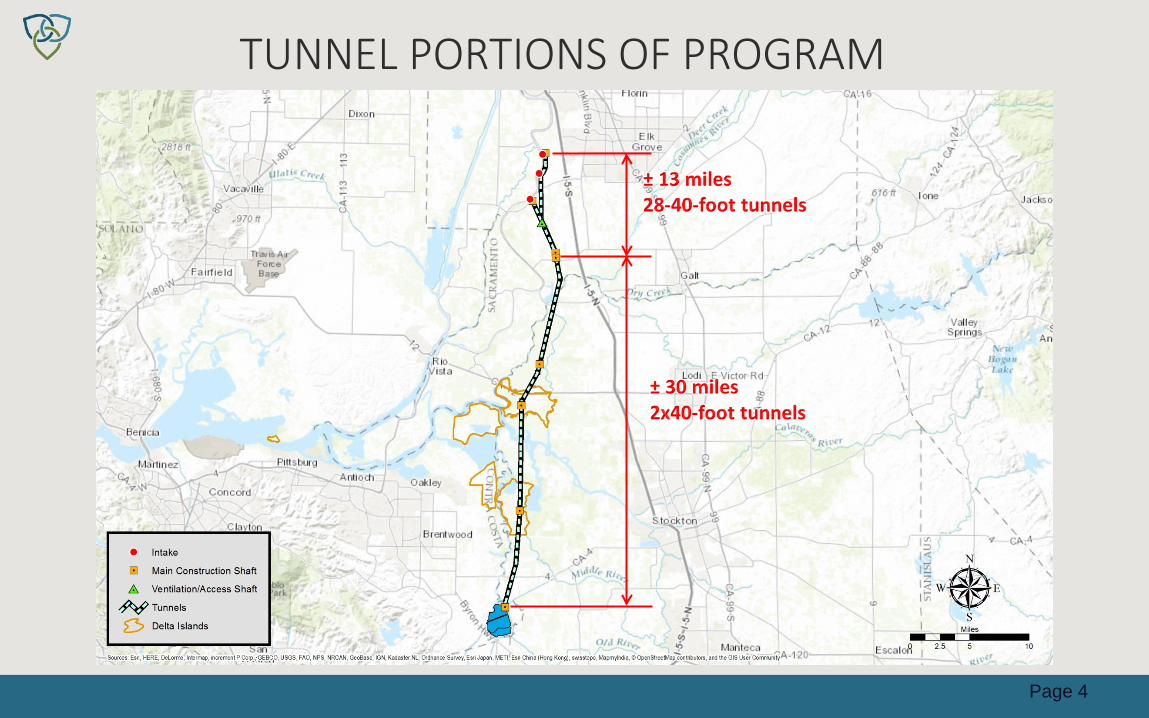
TUNNEL PORTIONS OF PROGRAM
Page 4
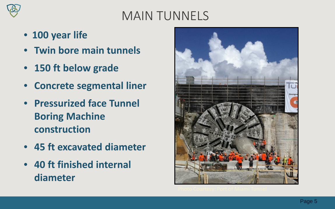
MAIN TUNNELS
Photo Courtesy: Port of Miami Tunnel
• 100 year life • Twin bore main tunnels
• 150 ft below grade
• Concrete segmental liner
• Pressurized face Tunnel Boring Machine construction
• 45 ft excavated diameter
• 40 ft finished internal diameter
Page 5

LARGE DIAMETER TUNNEL BORING MACHINE PROJECTS
42 43.3 45 45.5 46 47.5 49.5 50.6 51.2
57.5 58
0
10
20
30
40
50
60
70
Port
of
Mia
mi
SMAR
TM
alay
sia
CA W
ater
Fix
Thim
ble
Shoa
ls
Hong
Kon
gTM
CLK
East
Wat
ervi
ewAu
ckla
nd N
Z
Mad
rid M
30
Wuh
anM
etro
Chi
na
Spar
vo It
aly
Seat
tle S
R99
Hong
Kon
gTM
CLK
Wes
t
TBM
Dia
met
er (f
t)
Page 6

REVIEW OF OTHER MEGA-TUNNEL PROJECTS
• The Eurasia Tunnel - Turkey • Lee Tunnel - London • Port Of Miami Tunnel - Florida • East Side Access - New York • Blue Plains Tunnel Project - District of Columbia • Bay Tunnel - San Francisco • Willamette River Combined Sewer Outfall Program -
Portland • Gotthard Base Tunnel - Swiss Alps • SR-99 Alaskan Way Replacement - Seattle
Page 7

THE EURASIA TUNNEL – TURKEY
Bedrock
Sand & Gravel
Bedrock Seismic Joints
2.1 miles
320 ft
Page 8

THE EURASIA TUNNEL – TURKEY
Project Information
• Transportation Tunnel 45 ft Internal Diameter (ID) x 2.1 miles
• 320 ft deep
• Completed Dec 2016 – 3 months ahead of schedule
• Challenges − Complex geology, seismic
deformations, and high groundwater pressure
Page 9

LEE TUNNEL - LONDON Abby Mills Pump
Station
Beckton Sewage Treatment Works
Lee Tunnel
Page 10

LEE TUNNEL – LONDON
Project Information • 23.6 ft ID x 4.3 mile Combined
Sewer Outfall (CSO) Tunnel
• 160 ft deep
• Completed December 2015 – on schedule – Within budget
• Challenges − Groundwater contamination,
complexity of Tunnel Boring Machine launch, and spoil removal
Page 11

PORT OF MIAMI TUNNEL - FLORIDA
Watson Island Construction
Eastbound Tunnel
Westbound Tunnel
Dodge Island Construction
Page 12

PORT OF MIAMI TUNNEL
Project Information • (2) 39 ft ID x 4,200 ft Long Transportation
Tunnels
• 120 ft deep
• Completion May 2014 – On schedule – Within budget
• Challenges − Additional geotechnical investigations
were critical to confirm the ground model
Page 13

EAST SIDE ACCESS – NEW YORK
Page 14
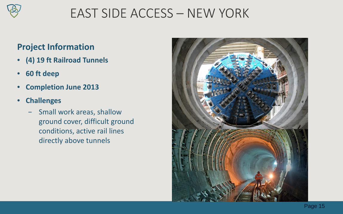
EAST SIDE ACCESS – NEW YORK
Project Information • (4) 19 ft Railroad Tunnels
• 60 ft deep
• Completion June 2013
• Challenges − Small work areas, shallow
ground cover, difficult ground conditions, active rail lines directly above tunnels
Page 15

BLUE PLAINS TUNNEL PROJECT- DISTRICT OF COLUMBIA
Blue Plains Tunnel
Page 16

BLUE PLAINS TUNNEL PROJECT
Project Information • 23 ft ID x 24,200 ft CSO Tunnel • 160 ft deep • Completed Dec 2015
– 3 months ahead of schedule – Under budget
• Challenges – Institutional resistance to
change, existing infrastructure above tunne, and environmental permitting
Page 17

BAY TUNNEL – SAN FRANCISCO
Page 18

BAY TUNNEL – SAN FRANCISCO
Project Information
• 15 ft ID x 5 mile water tunnel • 110 ft deep • Completed Oct, 2014
– on schedule – Within budget
• Challenges − Variable ground, contaminated soil,
disposal of tunnel material, long tunnel drive, and high ground water pressure (3.5 bar)
Page 19
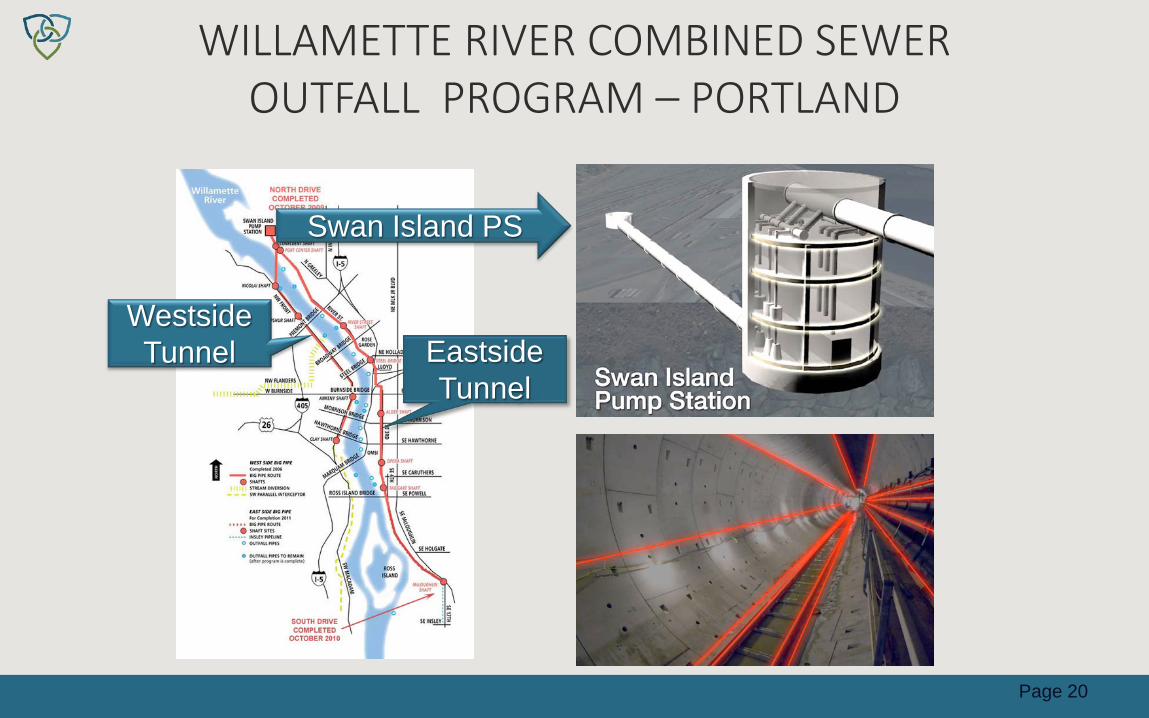
WILLAMETTE RIVER COMBINED SEWER OUTFALL PROGRAM – PORTLAND
Eastside Tunnel
Westside Tunnel
Swan Island PS
Page 20

WILLAMETTE RIVER COMBINED SEWER OUTFALL PROGRAM – PORTLAND
Project Information • (1) 14 ft ID x 3.5 mile 120 ft deep and (1)
22 ft ID x 6 mile
• 150 ft deep CSO tunnels
• Construction Complete Feb 2012 – 8 months ahead of schedule
– Under budget
• Challenges
– Schedule, existing infrastructure, groundwater, difficult ground conditions, soil modification, and subcontract changes
Page 21

GOTTHARD BASE TUNNEL - SWISS ALPS
France
Switzerland
Italy
Gotthard Base Tunnel
Page 22
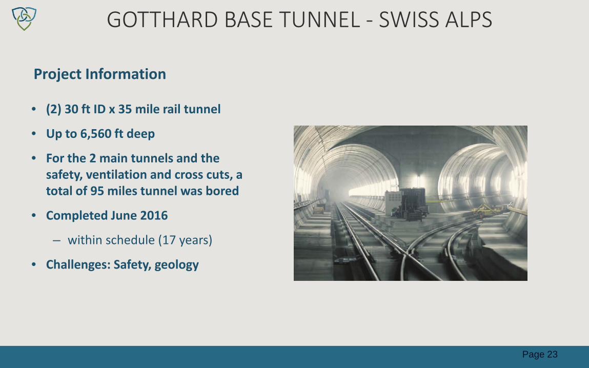
GOTTHARD BASE TUNNEL - SWISS ALPS
Project Information
• (2) 30 ft ID x 35 mile rail tunnel
• Up to 6,560 ft deep
• For the 2 main tunnels and the safety, ventilation and cross cuts, a total of 95 miles tunnel was bored
• Completed June 2016
– within schedule (17 years)
• Challenges: Safety, geology
Page 23

SR-99 ALASKAN WAY REPLACEMENT-SEATTLE
Top of tunnel
Underground View Page 24
Building pile foundations
Viaduct pile foundations

Project Information
• 53 ft ID x 2 mile transportation tunnel
• Construction schedule
– approximately 2 year delay
• Challenges
– Equipment malfunction, existing pile foundations and other infrastructure, difficult ground
SR-99 ALASKAN WAY TUNNEL-SEATTLE
Page 25

0
1,000
2,000
3,000
4,000
5,000
6,000
7,000
Aug-
13O
ct-1
3De
c-13
Feb-
14Ap
r-14
Jun-
14Au
g-14
Oct
-14
Dec-
14Fe
b-15
Apr-
15Ju
n-15
Aug-
15O
ct-1
5De
c-15
Feb-
16Ap
r-16
Jun-
16Au
g-16
Oct
-16
Dec-
16Fe
b-17
Dec 2013: Stoppage begins
Access pit constr begins
Arrival at access pit
TBM exits access pit
PM
PM
PM
PM PM = Planned maintenance
SR-99 ALASKAN WAY TUNNELING PROGRESS
Page 26
Line
ar fe
et o
f tun
nel b
ored

LESSONS LEARNED • Conduct an extensive and thorough geotechnical program
• Utilize TBM technology that is well understood and project-proven
• Select only experienced tunneling contractors
• Implement a comprehensive monitoring and inspection program
• Implement proactive risk management strategy at all stages
Page 27

RELEVANT EXAMPLES OF PILE DRIVING AND LEVEE/STRUCTURE PERFORMANCE
• Alternative Intake on Victoria Canal • Freeport Intake • Sankey Diversion Facility • Cosumnus Power Plant • Several DWR projects in the Delta- Extensive Experience
Page 28

ALTERNATIVE INTAKE ON VICTORIA ISLAND
• 2008-2009
• On the Victoria Canal North Bank
• Approx. 390 sheet and concrete piles driven
• Driven by impact hammer for foundation piles
• No observed damage
Page 29

• 2007-2008
• On the Sac River East Levee Bank
• ~ 800 ft. from the West Levee bank
• Approx. 520 sheet and H piles driven
• Driven by vibratory and impact hammers
• No observed damage
FREEPORT INTAKE ON SACRAMENTO RIVER
Page 30

SANKEY DIVERSION FACILITY ON SACRAMENTO RIVER
• 2010-2011 • On the Sac River East
Levee Bank • ~550 ft. from the West
Levee Bank • Approx. 270 piles driven • Driven by impact and
vibratory hammers • No observed damage
Page 31

COSUMNUS POWER PLANT
• 2004
• 1,800 feet from Rancho Seco plant
• Approx. 2,000 piles
• driven by impact hammer
• No observed damages
Page 32

SHEET AND PILE DRIVING TECHNOLOGIES
• Sheet Piles – Used for coffer dam (in-water) construction – Vibratory hammers (70%) – Impact hammers (30%)
• Foundation Piles – Either Driven piles or Cast-in-drilled hole piles – Type depends on final geotech studies
Page 33

DWR SHEET AND PILE DRIVING COMMITMENTS (ENVIRONMENTAL COMMITMENTS 3B.2.1.1-2)
• Perform pre-construction surveys to establish baseline conditions
• Collect subsurface data • Perform geotechnical analyses • Select appropriate pile types and installation
methods • Implement monitoring programs during construction
Page 34

ENCROACHMENT INTO RIVER CHANNEL
• Under jurisdiction of USACE and CVFPB
• Modifications must meet USACE’s 408 requirements
• Safety assurance review by an independent panel of experts
• Must maintain “project’” conditions, purposes or outputs
Page 35
TRAFFIC ON LEVEES
• Very little project traffic is planned to traverse on levees – SR-160 is constructed on top of a levee
• Suitable for H20 loading • Already experiences extensive traffic
Page 36

LEVEE ROAD USAGE FOR WATERFIX
BACON ISLAND: 1.6 MILES
MANDEVILLE ISLAND: 4.6 MILES
Page 37

TRAFFIC ON LEVEES • DWR’s commitments to levees and levee roads
– Preconstruction assessment – Ground stabilization, if needed – Monitoring during construction – Return roadways to preconstruction condition
• Final EIR/EIS Commitments – Mitigation Measures: TRANS-2a, 2b and 2c – Environmental Commitment 3B.2.1.2
• Settlement Monitoring and Response Program
Page 38
EXISTING WATER DIVERSIONS
• Total number of effected water rights – Temporarily effected: 10 – Permanently effected: 5
• Mitigations for temporarily effected diversions – Prior to construction, extend pipes and adjust pump
locations on landside – Provide new groundwater wells – Provide alternate water supply from a permitted source
Page 39

EXISTING WATER DIVERSIONS
• Mitigations for permanently effected diversions – Provide temporary mitigation measures until the mitigation
measures below are completed: • Relocate existing diversions outside of the intake structure
footprint • Provide a new turnout from the proposed CWF sedimentation
basins
Page 40

INTAKE 2 DIVERSIONS
• Diversion S021406 – Falls outside of intake
footprint – Within road relocation – Will not be permanently
affected – Temporary impacts – Maintain quality and
quantity of flow
Page 41

INTAKE 3 DIVERSIONS
• Diversion S016915 – Falls outside of intake
footprint – Within road relocation – Will not be permanently
affected – Temporary impacts – Maintain quality and
quantity of flow
Page 42

ISSUE: POTENTIAL IMPACT OF TUNNELING UNDER/NEAR EXISTING INFRASTRUCTURE
• EBMUD’s Concerns – Tunnel construction will undermine, cause settlement and
reduce ground support of aqueduct foundation piles – CWF tunnel profile will intersect with existing and planned
infrastructure
Page 43

DWR COMMITMENTS TO AVOID IMPACTS TO INFRASTRUCTURE
• Existing DWR Commitments, outlined in: – Appendix 3B, Section 3B.2.1 – Ground treatment plan, ground settlement monitoring, and
response plan
• Additionally, DWR Commits to: – Work collaboratively with EBMUD and other agencies on
these issues during preliminary and final design – Provide contract specs and maintenance requirements to
ensure safe tunneling – Provide appropriate levels of on-site inspection to ensure
successful results
Page 44

ISSUE: POTENTIAL IMPACT OF TUNNEL SEEPAGE ON EXISTING INFRASTRUCTURE
• Concerns expressed by protestants over potential leakage from tunnels –No estimates of potential leakage rates
presented by protestants –No analysis of potential impacts presented
by protestants
Page 45

TUNNEL LEAKAGE STUDY – ARUP 2017
• Findings – Current CWF configuration minimizes potential for
tunnel leakage • In most cases, tunnel internal pressure is less than
external water pressures – For 73.5 miles of tunnel:
• leakage rate estimated at 0.7 cfs • Inflow rate estimated at 3.7 cfs • Overall inflow rate: 3.0 cfs
Page 46

SEATTLE TUNNEL INFLOWS 57-FOOT OUTSIDE DIAMETER TUNNEL
Page 47

HONG KONG TUNNELS INFLOWS 46-FOOT OUTSIDE DIAMETER TUNNELS
Tuen Mun-Chek Lap Kok Tunnel
Liantang Boundary Control Point Tunnel
Page 48

DWR COMMITMENTS TO REDUCE TUNNEL LEAKAGE/INFLOW
• Specify high-quality concrete in segments, and ensure results with proper QA/QC
• Provide careful details for inserts and grout holes • Provide high quality segment connections and gasket details • Specify “tight” build tolerances • Provide good field inspection to enforce superior
construction builds
Page 49

ISSUE: CONCERN OVER POWER LINES CROSSING AQUEDUCT
• Potential for induced current to lead to corrosion • Potential for induced current to lead to shock hazard • Potential for power line to fall and strike aqueduct
Page 50

DWR COMMITMENTS TO REDUCE POWER LINE RISK POTENTIAL
• Existing DWR Commitments, outlined in: – Appendix 3B, Section 3B.2.3, and Section 3b.4.30 (AMM
30) – Design and construction transmission lines in accordance
with Electrical Power and Transmission Line Design Guidelines
• Additionally, DWR Commits to: – Work collaboratively with EBMUD and other agencies on
these issues during preliminary and final design – Provide contract specs and appropriate levels of on-site
inspection and on-going observation to ensure successful results
Page 51

SEA LEVEL RISE FOR FLOOD PROTECTION
• Used 55 inches of SLR at Golden Gate Bridge
• SLR impact decreases farther inland
• 18 inches of SLR added above 200-yr flood level for intakes
• To be reviewed and updated during next engineering phase
Page 52