engineering service bulletin se encore speed reducersse encore speed ... · se encore speed...
TRANSCRIPT
SE Encore Speed ReducersSE Encore Speed Reducers
Engineering Service Bulletin15Engineering Service Bulletin
1
SE Encore Installation, Operation, and Lubrication Instructions
Multimount
Integral
Modified
2
SE Encore Speed ReducersSE Encore Speed Reducers
Engineering Service Bulletin15Engineering Service Bulletin
I. SELECTIONThe selection of the appropriate speed reducer for a givenapplication requires that all factors affecting the operation ofthe reducer be given careful consideration. Service factorsmust be applied to catalog ratings depending on the type ofprime mover used, the severity of the application, and durationof daily service. Many application and SE Encore worm gearspeed reducer selection criteria are discussed in the SEEncore catalog that is available at www.WINSMITH.com. Forpersonal assistance, please speak with a local Winsmithsales representative whose contact information is also available on the website.
II.INSTALLATION
1. Shaft Alignment and Loading
A. Guard against unusual stresses and overloads by accurately aligning the various drive members (motor,speed reducer, coupling, sprocket, sheave, gear, etc.).
B. Flexible couplings are recommended if a prime movershaft is to be directly connected to the input shaft or ifthe output shaft is directly connected to the driven shaft.Note: Flexible couplings have a limited capacity for misalignment. Ensure that shaft alignments are withinthe limits recommended by the coupling manufacturer atinstallation. Even slight misalignments in a rigid mountingsystem may bring about binding, large vibration forces,or excessive overhung loading; each in itself promotingpremature bearing, shaft, or speed reducer failure. Donot excessively force couplings or other connectiondevices onto either input or output shafts; the result maybe permanent bearing damage. Ensure all shaft keysare captive and secured before operation.
C. A common base plate supporting the motor and reducerwill help preserve the original alignment between thereducer and the motor shaft. If a structural steel base isused, the plate should be at least equal in thickness tothe diameter of the base plated fastening bolts. In addition, the structure supporting the base plate mustbe sufficiently rigid that it prevents excessive flexingduring normal operation.
D. Vibration tends to loosen fasteners even if they are initially tight. After the first week or two of operation, allfasteners within the drive assembly should be retightened.Doweling the motor and speed reducer to the baseplate will help maintain alignment.
E. Excessive thrust or overhung loads on the input or outputshafts of a gear reducer may cause premature failures of the bearings and/or shafts. Mount gears, pulleys andsprockets as close to the housing as possible to minimize such loads. Do not exceed catalog loads.
2. Mounting Positions
A. Single Reduction Speed Reducers and Helical Gear Ratio Multipliers
All SE Encore single reduction speed reducers and allhelical gear ratio multipliers are filled with lubricant atWinsmith and can be mounted in any of the positionsidentified in Figure 3. Grease fittings (not shown inFigure 3) are used to lubricate bearings when the motorspeed is below 1160 RPM. Please reference Section IIIof this document, “Lubrication & Maintenance,” fordetails related to proper lubrication levels.
B. Double Reduction Speed Reducers Worm/Worm andHelical/Worm Double Reduction
The SE Encore double reduction speed reducers aredesigned to be mounted in any of the “Standard” positionsshown in Figure 4. These reducers are factory filled withlubricant to a level that is appropriate for these standardmounting positions. Standard models have an oil levelthat is common to both housings. Grease fittings (notshown in Figure 4) are used to lubricate bearings whenthe motor speed is below 1160 RPM. If an additionalmounting position not shown in Figure 4 is required,please speak with a local Winsmith sales representativewhose contact information is available on the website,www.WINSMITH.com.
3. Mounting ConsiderationsThe recommended mounting for a hollow shaft reducerincorporates a torque arm. The recommended mounting of areducer with a flange/bracket mounting on a conveyor headshaft uses a pillow block or flange bearing on the oppositeside of the conveyor from the speed reducer as a supportbearing. This provides three bearings for alignment purposes.It is difficult to maintain and align a system with a rigidlymounted bearing close to a rigidly mounted speed reducer.It is extremely important to “custom align” and “custom shim”all components prior to tightening mounting bolts when usinga rigid mounting approach. This minimizes misalignment thatis caused by excessive loads. Select an appropriate keywhen using a bushing in the output bore of any hollow outputshaft speed reducer.
3
SE Encore Speed ReducersSE Encore Speed Reducers
Engineering Service Bulletin15Engineering Service Bulletin
4. C Face Motor MountingProcedures
A. C Face/Quill Motor Mounting
1. Check the motor and reducer mounting registers for nicksthat could interfere with assembly; remove if necessary.
2. Remove protective plastic from the reducer input shaft.The bore has been coated with an anti-seize compound.
3. Align the motor shaft and key with keyway in bore andslide motor up to input adaptor.
4. Position the motor conduit box as desired.
5. Secure the motor to the reducer using the supplied fasteners. Ensure proper motor seating before tighteningthe fasteners. If the motor does not readily seat itself,check for axial movement of the motor shaft key as thiscan cause interference. Staking the keyway adjacent tothe motor key will help prevent axial movement of thekey during the mounting procedure. Draw down evenlyon the fasteners to avoid bending the motor shaft.Tighten the fasteners to the appropriate torque per thesize of the fastener.
B. C Face Coupling Motor Mounting
1. Check the motor and reducer mounting registers fornicks that could interfere with assembly. Remove if necessary.
2. When assembling the motor and coupling, the couplinghalves should be evenly spaced on each shaft to obtainproper engagement. The following describes a methodfor doing this:
3. Determine the assembled shaft clearance by measuringthe distance from the C Face to the reducer shaft endand subtracting the motor shaft length. Mount andsecure the motor shaft side of the coupling such that thespider-end of the coupling is located one half of theclearance distance beyond the motor shaft. Mount thereducer coupling half and coupling spider onto the reducershaft in its approximate position, but do not secure.
4. Locate the motor conduit box in the desired position and secure the motor to the reducer input adaptor usingthe fasteners provided. Tighten the fasteners to theappropriate torque per the size of the fastener.
5. Using the access hole in the input adaptor, slide thecoupling together and tighten the set screw.
5. Speed Reducer Assembly/ Disassembly Instructions
Contact Winsmith or a local sales representative for a copy ofSE Encore Speed Reducers Disassembly and ReassemblyInstructions – Engineering Service Bulletin #16.
6. Sealed vs. Vented Speed Reducer Operation
All SE Encore series speed reducers are designed to operatesealed or vented. Deciding whether a speed reducer shouldoperate sealed or vented requires an understanding of theapplication, the environment, the operation of radial shaftseals, and a review of the fundamentals of thermodynamicsthat govern the temperature and pressure relationship in thespeed reducer.
Any significant increase in pressure in a sealed speedreducer decreases the operational service life of the radiallip seals. A pressure change of only 5 psi may reduce theseal life by as much as one third. There are two importantphenomena that cause an increase in the internal pressureof a sealed speed reducer. First, the change of internal pressure during operation is proportional to the change ofinternal temperature that occurs during normal operation.The relationship follows the combined gas law expressed as
P1V1 / T1 = P2V2 / T2
Secondly, radial lip seals can ingest or “pump” air into aspeed reducer regardless of whether it is operating sealedor vented. While the rate of ingestion is highly variable anddependant on running time and speed, under continuousoperating conditions the net effect of “pumped” air to thetotal pressure increase is significant. Venting, or the use of abreather vent, is the only absolute method of eliminating thepressure increase in a speed reducer caused by both pumping and thermal expansion.
In some applications, the duty cycle of the speed reducer isintermittent, the run times short, and the temperatureincrease modest. While sealing the reducer during operationsubsequently increases the pressure in these applications,the increase may be very small and therefore have minimalimpact on the seal service life. Additionally, operating asealed speed reducer may be the best choice in applicationswhere external airborne contamination causes a greaterreduction in overall speed reducer service life than the negativeimpact of the internal pressure increase. The machinebuilder or the end equipment user should determine whether
SE Encore Speed ReducersSE Encore Speed Reducers
Engineering Service Bulletin15Engineering Service Bulletin
sealing or venting the speed reducer is the best choice for a specific application as this decision has a direct impact on the seal service life. A more detailed discussion of the factors influencing seal wear and seal service life follows.
Internal Temperature and Pressure Increase in a SealedSpeed Reducer
A speed reducer experiences a significant internal temperatureincrease due to operating loads. The change in temperatureof an operating speed reducer (from static ambient temperature to maximum operating temperature) oftenexceeds 130° Fahrenheit. In a sealed speed reducer, the
increasing temperature results in a corresponding pressureincrease as described by the combined gas law:
P1V1 / T1 = P2V2 / T2In a closed system (e.g. sealed reducer), any change in temperature from one state of equilibrium to the next state ofequilibrium results in a corresponding change in both oil volumeand internal pressure. Moreover, the thermal expansion ofthe lubricant in the reducer can have a considerable effecton the pressure, temperature, and volume relationship. Theinfluence of the lubricant’s thermal expansion depends onthe percent volume occupied by the lubricant compared to
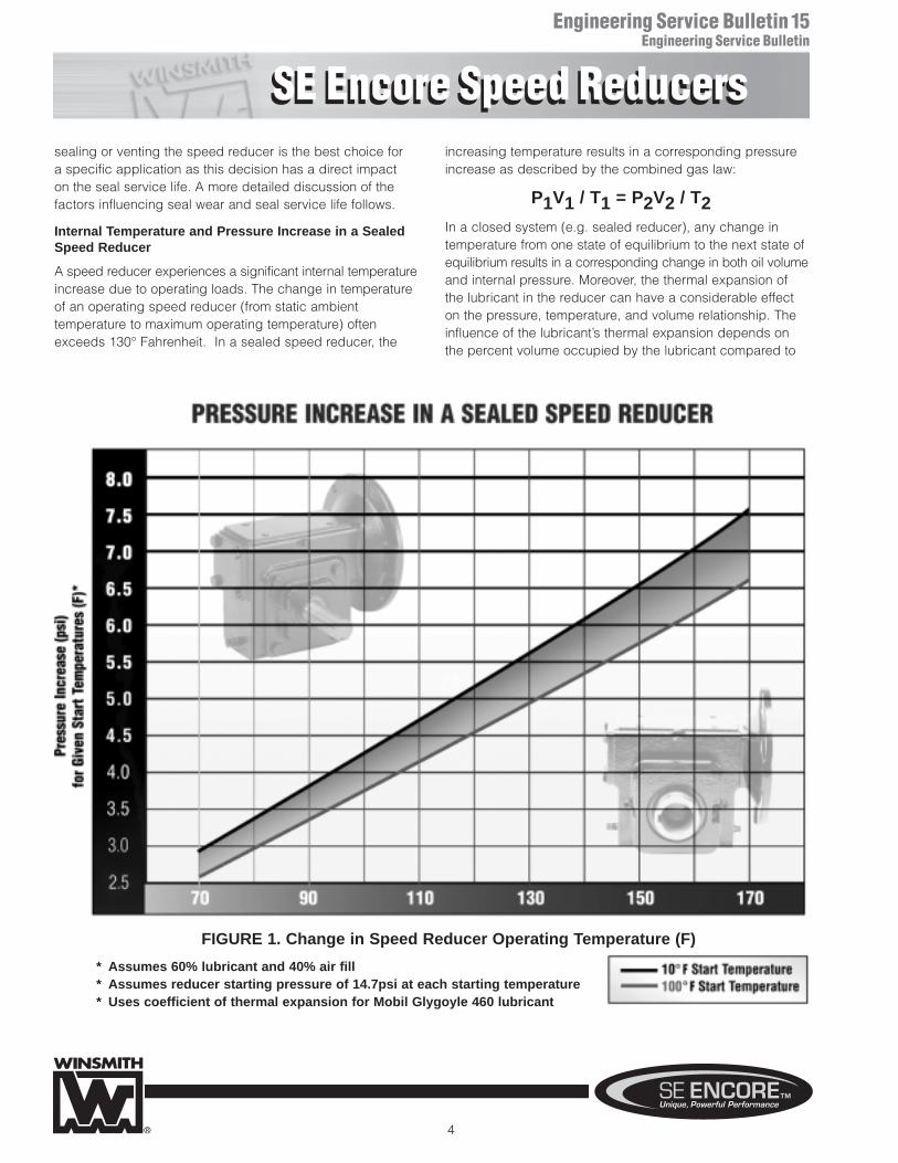
* Assumes 60% lubricant and 40% air fill* Assumes reducer starting pressure of 14.7psi at each starting temperature* Uses coefficient of thermal expansion for Mobil Glygoyle 460 lubricant
FIGURE 1. Change in Speed Reducer Operating Temperature (F)
4
SE Encore Speed ReducersSE Encore Speed Reducers
Engineering Service Bulletin15Engineering Service Bulletin
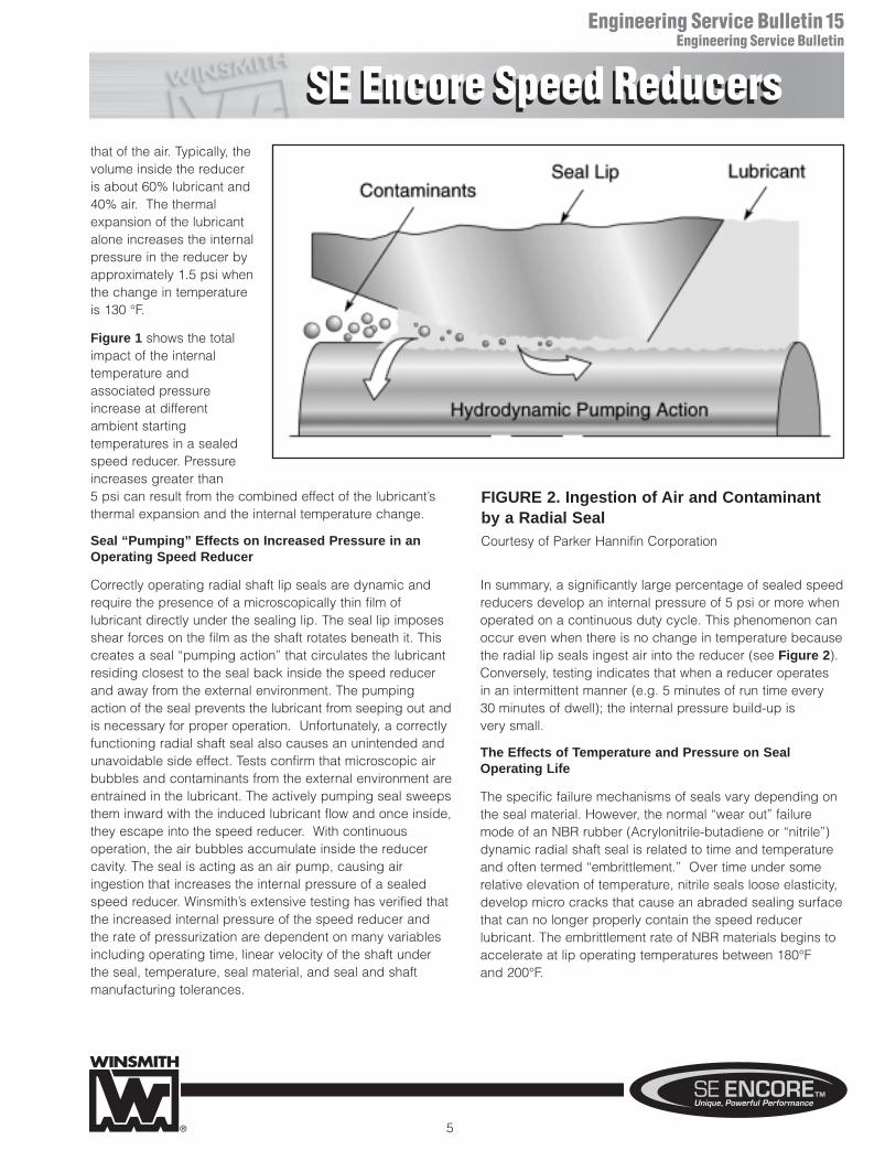
that of the air. Typically, thevolume inside the reduceris about 60% lubricant and40% air. The thermalexpansion of the lubricantalone increases the internalpressure in the reducer byapproximately 1.5 psi whenthe change in temperatureis 130 °F.
Figure 1 shows the totalimpact of the internal temperature and associated pressureincrease at different ambient starting temperatures in a sealedspeed reducer. Pressureincreases greater than 5 psi can result from the combined effect of the lubricant’sthermal expansion and the internal temperature change.
Seal “Pumping” Effects on Increased Pressure in anOperating Speed Reducer
Correctly operating radial shaft lip seals are dynamic andrequire the presence of a microscopically thin film of lubricant directly under the sealing lip. The seal lip imposesshear forces on the film as the shaft rotates beneath it. Thiscreates a seal “pumping action” that circulates the lubricantresiding closest to the seal back inside the speed reducerand away from the external environment. The pumpingaction of the seal prevents the lubricant from seeping out andis necessary for proper operation. Unfortunately, a correctlyfunctioning radial shaft seal also causes an unintended andunavoidable side effect. Tests confirm that microscopic airbubbles and contaminants from the external environment areentrained in the lubricant. The actively pumping seal sweepsthem inward with the induced lubricant flow and once inside,they escape into the speed reducer. With continuous operation, the air bubbles accumulate inside the reducercavity. The seal is acting as an air pump, causing air ingestion that increases the internal pressure of a sealedspeed reducer. Winsmith’s extensive testing has verified thatthe increased internal pressure of the speed reducer and the rate of pressurization are dependent on many variablesincluding operating time, linear velocity of the shaft under the seal, temperature, seal material, and seal and shaft manufacturing tolerances.
In summary, a significantly large percentage of sealed speedreducers develop an internal pressure of 5 psi or more whenoperated on a continuous duty cycle. This phenomenon canoccur even when there is no change in temperature becausethe radial lip seals ingest air into the reducer (see Figure 2).Conversely, testing indicates that when a reducer operates in an intermittent manner (e.g. 5 minutes of run time every 30 minutes of dwell); the internal pressure build-up is very small.
The Effects of Temperature and Pressure on SealOperating Life
The specific failure mechanisms of seals vary depending onthe seal material. However, the normal “wear out” failuremode of an NBR rubber (Acrylonitrile-butadiene or “nitrile”)dynamic radial shaft seal is related to time and temperatureand often termed “embrittlement.” Over time under somerelative elevation of temperature, nitrile seals loose elasticity,develop micro cracks that cause an abraded sealing surfacethat can no longer properly contain the speed reducer lubricant. The embrittlement rate of NBR materials begins toaccelerate at lip operating temperatures between 180°F and 200°F.
5
FIGURE 2. Ingestion of Air and Contaminantby a Radial SealCourtesy of Parker Hannifin Corporation
SE Encore Speed ReducersSE Encore Speed Reducers
Engineering Service Bulletin15Engineering Service Bulletin
The impact of increasing temperature and pressure in asealed speed reducer on the service life of an NBR seal hasbeen assessed by numerous seal manufacturers. While theresults of these tests vary depending on variables such asthe actual seal lip temperature, they indicate that a changein pressure as small as 5 psi can reduce the expected sealservice life by one third. This is because a positive internalpressure differential in a speed reducer causes the shaft lipseals to exert a higher radial force on the shaft. Underdynamic conditions, this force increases the lip seal contactarea on the shaft, increasing the friction, and thereby creatinga correspondingly higher temperature between the shaft and the lip seal. This increase is directly proportional to theamount of radial force on the seal and to the speed of theshaft at the seal interface and causes a decrease in the seal life.
All SE Encore speed reducers with a quill input adaptor use special HNBR (hydrogenated nitrile butadiene rubber) or fluoroelastomer (aka Viton®) materials on all input shaftsbecause these materials are tolerant of higher lip operatingtemperatures. The typical failure mode of HNBR material isblistering at the seal surface.
Performance Issues with Bladders and Expansion Chambers
Various speed reducer design approaches aimed at eliminating the internal pressure increase have incorporatedinternal collapsible diaphragms or bladders. Eliminating thepressure increase requires that the bladder or diaphragmcollapse at very low pressures and have a volume that sufficiently accommodates the expansion of the air and thelubricant. In a reducer with a two inch center distance, theinternal volume is between 30 in3 and 40 in3. Assuming thevolume is 60% lubricant and 40% air and applying the previously discussed combined gas law over a temperaturechange of 130°F (70°F start, 200°F final), the size of an internal diaphragm or bladder required to prevent a pressureincrease must be between 3.9 in3 and 5.2 in3. In most typicalspeed reducers, there is insufficient internal space for sucha large bladder. Moreover, while some internal expansionchambers are effective in limiting or reducing internal pressure rise due to temperature changes, none are com-pletely effective in avoiding the pressure build up related toseal air pumping action associated with continuous dutycycle applications.
Applications Determine When Sealing a Speed Reduceris Preferred to Venting
As covered in the preceding discussion, sealing a reducercan increase the internal pressure which results indecreased seal service life. This is especially prevalent whenoperating under continuous duty conditions. However, thereare certain applications where the speed reducer duty cycleis highly intermittent, and run times are short with light average duty loads. Testing and field experience indicatethat small internal pressure increases (1 – 2 psi) have a minimal effect on the seal service life.
Another application dependent situation where sealed reducer operation is preferred occurs when the external airenvironment is extremely contaminated with material that, ifdrawn into the reducer through a vent, can rapidly reduceseal, bearing, or worm gear life. In these applications, theincreased pressure resulting from operating a sealed reducercan still have a significantly negative effect on seal life and,in these cases, require more frequent seal replacement.However, the reducer life may be lengthened by operatingsealed rather than operating with an open vent in thesetypes of harsh environments. Further, the machine builder or equipment operator might determine that the convenienceof operating a sealed speed reducer outweighs the negativeresult of reduced seal service life.
The Winsmith two (2) year warranty on defects in partsand workmanship remains unaffected whether an SEEncore worm gear speed reducer operates with or without a vent since the vent/sealed decision only affectsthe service life of the speed reducer wear components.
In conclusion, there are three fundamental factors that govern the speed reducer seal/vent decision. First, as thetemperature increases in a sealed reducer, so will the pressure.Second, the radial shaft seals are designed to “pump” lubricant back into the speed reducer. This pumping actionalso causes an ingestion of air that increases the internalpressure. Any increase of pressure causes decreaseddynamic radial seal life. Venting is the most cost effectivemethod of eliminating the pressure. Finally, when extremeenvironmental conditions cause component or seal wear inexcess of that caused by an increased internal pressure,sealing a speed reducer is the best likely alternative.However, under these conditions, seal wear is apt to takeplace at higher than predicted rates.
6
SE Encore Speed ReducersSE Encore Speed Reducers
Engineering Service Bulletin15Engineering Service Bulletin
SE Encore Venting Solution is a Standard Feature
The SE Encore worm gear speed reducer series can satisfactorily operate sealed or vented. Each reducer is supplied with an optional “open-closed vent” that can beinstalled by the equipment builder or the equipment user.This exclusive Winsmith vent is made from black DuPont™Zytel® Nylon with UV protection. The vent’s design incorporatesa labyrinth with a dust/splash cap that minimizes contaminateand water incursion from the external environment createdby general, harsh, and outdoor applications. The reducerhousing offers multiple locations for vent installation dependingon the final reducer mounting position on the equipmentTurning the top cap to the closed position ensures that no oildrains while the equipment is in transit to the operating location. Turning the top cap counter clockwise, by hand,opens the vent prior to running the speed reducer A specialscrew driver slot molded into the cap allows easy actuationwhen access is limited. The vent should be installed in thehighest pipe plug location available based on the actualmounting orientation of the speed reducer on the operatingequipment. Additionally, a bright yellow plastic tag is providedwith the vent that reads:
“IMPORTANT - VENT REQUIRES ACTIVATION
THIS REDUCER HAS BEEN SHIPPED TO YOU WITH THEVENT IN THE CLOSED POSITION – IT IS IMPORTANT TOOPEN THE VENT BY MAKING A ONE QUARTER TURN
COUNTER CLOCKWISE”
III. LUBRICATION &MAINTENANCE
NOTE: SE Encore worm gear speedreducers are factory filled with MobilGlygoyle 460 (PAG) lubricant. The use of other lubricants may result insubstantially lower torque capacity andis not recommended by Winsmith. Ifother lubricants are used, a thoroughflushing procedure is required.
1. Factory Filling and UniversalMounting
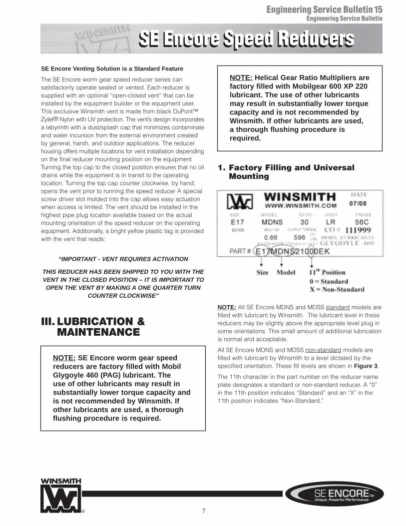
NOTE: All SE Encore MDNS and MDSS standard models arefilled with lubricant by Winsmith. The lubricant level in thesereducers may be slightly above the appropriate level plug insome orientations. This small amount of additional lubricationis normal and acceptable.
All SE Encore MDNS and MDSS non-standard models arefilled with lubricant by Winsmith to a level dictated by thespecified orientation. These fill levels are shown in Figure 3.
The 11th character in the part number on the reducer nameplate designates a standard or non-standard reducer. A “0”in the 11th position indicates “Standard” and an “X” in the11th position indicates “Non-Standard.”
7
NOTE: Helical Gear Ratio Multipliers arefactory filled with Mobilgear 600 XP 220lubricant. The use of other lubricantsmay result in substantially lower torquecapacity and is not recommended byWinsmith. If other lubricants are used, a thorough flushing procedure isrequired.
SE Encore Speed ReducersSE Encore Speed Reducers
Engineering Service Bulletin15Engineering Service Bulletin
2. Ambient TemperatureIf the ambient temperature during operation is outside of -18to 130 degrees F, please contact Winsmith.
3. Initial Start-UpPrior to start-up, the lubricant level should always bechecked. The proper lubricant fill level is dependent on thespeed reducer orientation during operation. The appropriatefill, drain, and level plug locations for a variety of models and orientations are shown in Figures 3 & 4. Grease fittings, not shown in Figures 3 & 4, are used to lubricate bearingswhen the motor speed is below 1160 rpm. If an alternatemounting position, not shown in Figures 3 & 4, is required,please contact a local sales representative or Winsmith for assistance.
The oil level should be checked, and adjusted if necessary, prior to operation using the oil level plugprovided and while the reducer is oriented in its operating position. Only Mobil Glygoyle 460 or compatible lubricant should be used for reducerscontaining worm gears. The Helical Gear RatioMultipliers should use Mobilgear 600 XP220 lubricant.
During the initial start-up operation, a break-in period is necessary before the reducer reaches maximum operatingefficiency. Winsmith recommends a gradual application ofload during the first several hours after start-up. The reducermay run hot during this initial break-in period. This is normal.A few drops of oil may weep from the lip seals during thebreak-in stage. After a short period of operation, clean offany excess oil around the shaft seals and recheck the oillevel; adjust if necessary.
4. Oil Change InstructionsWhen changing the oil for any reason, use only MobilGlygoyle 460 or other compatible PAG (Polyalkylene glycol)synthetic lubricants. If another oil type is used (PAO, MineralOil, etc.), the housing(s) must be drained and thoroughlyflushed with a light flushing oil prior to refilling. Do not mixdifferent lubricants in the reducer. Lubricant incompatibilitymany result in premature failure. Note: When changing oil,carefully inspect used oil to be sure there are no metal shavings, fragments and other signs of excessive wear.
The oil level should be checked after a short period of operation and adjusted if necessary. Each housing of a
double reduction model should be drained and filled independently when changing the oil. Visit our website,www.WINSMITH.com, for a detailed flushing procedure.
In many light duty, relatively clean ambient conditions, thelife of Mobil Glygoyle 460 is extended to the point where areducer can operate for the AGMA and ISO specified“Normal” reducer life of 25,000 hours without ever changingthe lubricant.
Note: The “Normal” reducer life of 25,000 hours specified inAGMA 6034-B92 and ISO TR14521 is highly applicationdependent. In Winsmith’s 100 years of experience, we havefound that the actual service life of many of our reducersexceeds 25,000 hours by several multiples.
Under severe conditions (rapid temperature changes, moist,dirty, or corrosive environments) it may be necessary tochange the oil at intervals of 1-3 months. Periodic examinationof oil samples taken from the reducer will help establish theappropriate interval.
The oil change procedure for all SE Encore speed reducers is similar. The appropriate oil fill, drain, and level plugs areidentified in Figures 3 & 4. Please note that these locationsare unique for each operating position shown. After drainingthe old lubricant, new lubricant should be added to the appropriate level plug shown.
Mounting Position and Lubricant Levels for Single andDouble Reduction ModelsOptimal lubricant level information for single and doublereduction models is shown in Figures 3 and 4. Lubricant levels are critical to the proper operation of all speed reducers.If a speed reducer was ordered and supplied for a specificmounting position, it should not be changed without contacting Winsmith. Altering the mounting position from thatwhich was specified may result in inadequate lubrication.Contact Winsmith or a local sales representative with questions regarding proper lubricant selection and level.
5. Long Term Storage or InfrequentOperation If a speed reducer is to stand idle for an extended period oftime, either prior to installation or during use, the housingshould be completely filled with oil. This will protect the interiorcomponents from corrosion due to internal condensation. Be sure to drain the oil to the proper level prior to placing the reducer into service. Contact Winsmith or a local sales representative with questions on long term storage.
8
SE Encore Speed ReducersSE Encore Speed Reducers
Engineering Service Bulletin15Engineering Service Bulletin
9
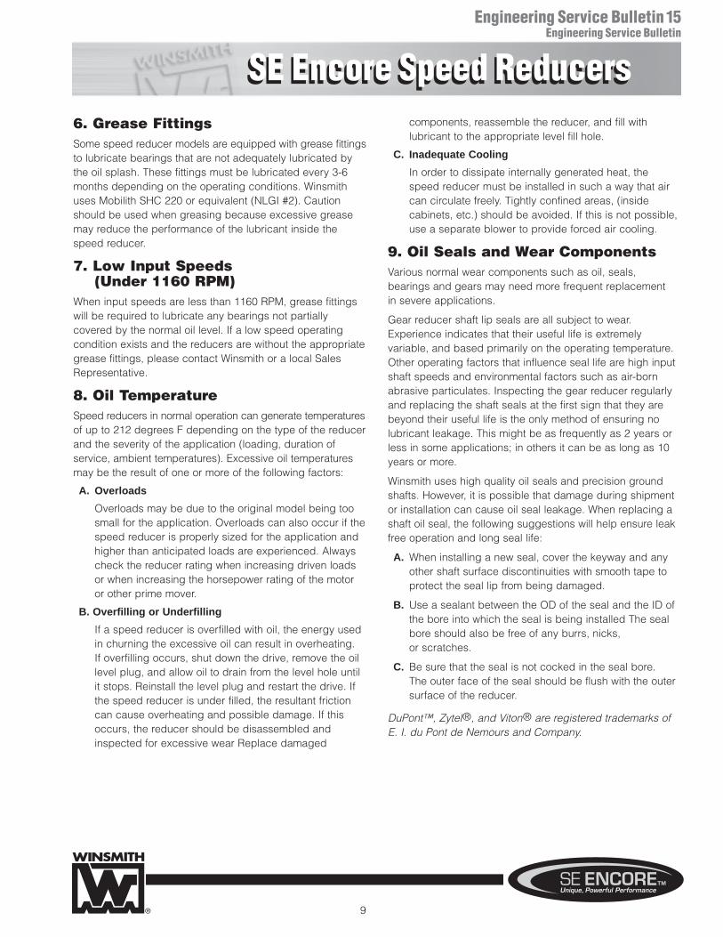
6. Grease FittingsSome speed reducer models are equipped with grease fittingsto lubricate bearings that are not adequately lubricated bythe oil splash. These fittings must be lubricated every 3-6months depending on the operating conditions. Winsmithuses Mobilith SHC 220 or equivalent (NLGI #2). Cautionshould be used when greasing because excessive greasemay reduce the performance of the lubricant inside thespeed reducer.
7. Low Input Speeds (Under 1160 RPM)
When input speeds are less than 1160 RPM, grease fittingswill be required to lubricate any bearings not partially covered by the normal oil level. If a low speed operatingcondition exists and the reducers are without the appropriategrease fittings, please contact Winsmith or a local SalesRepresentative.
8. Oil TemperatureSpeed reducers in normal operation can generate temperaturesof up to 212 degrees F depending on the type of the reducerand the severity of the application (loading, duration of service, ambient temperatures). Excessive oil temperaturesmay be the result of one or more of the following factors:
A. Overloads
Overloads may be due to the original model being toosmall for the application. Overloads can also occur if thespeed reducer is properly sized for the application andhigher than anticipated loads are experienced. Alwayscheck the reducer rating when increasing driven loadsor when increasing the horsepower rating of the motoror other prime mover.
B. Overfilling or Underfilling
If a speed reducer is overfilled with oil, the energy usedin churning the excessive oil can result in overheating. If overfilling occurs, shut down the drive, remove the oillevel plug, and allow oil to drain from the level hole untilit stops. Reinstall the level plug and restart the drive. Ifthe speed reducer is under filled, the resultant frictioncan cause overheating and possible damage. If thisoccurs, the reducer should be disassembled andinspected for excessive wear Replace damaged
components, reassemble the reducer, and fill with lubricant to the appropriate level fill hole.
C. Inadequate Cooling
In order to dissipate internally generated heat, thespeed reducer must be installed in such a way that aircan circulate freely. Tightly confined areas, (inside cabinets, etc.) should be avoided. If this is not possible,use a separate blower to provide forced air cooling.
9. Oil Seals and Wear ComponentsVarious normal wear components such as oil, seals, bearings and gears may need more frequent replacement in severe applications.
Gear reducer shaft lip seals are all subject to wear.Experience indicates that their useful life is extremely variable, and based primarily on the operating temperature.Other operating factors that influence seal life are high inputshaft speeds and environmental factors such as air-bornabrasive particulates. Inspecting the gear reducer regularlyand replacing the shaft seals at the first sign that they arebeyond their useful life is the only method of ensuring nolubricant leakage. This might be as frequently as 2 years orless in some applications; in others it can be as long as 10years or more.
Winsmith uses high quality oil seals and precision groundshafts. However, it is possible that damage during shipmentor installation can cause oil seal leakage. When replacing ashaft oil seal, the following suggestions will help ensure leakfree operation and long seal life:
A. When installing a new seal, cover the keyway and anyother shaft surface discontinuities with smooth tape toprotect the seal lip from being damaged.
B. Use a sealant between the OD of the seal and the ID ofthe bore into which the seal is being installed The sealbore should also be free of any burrs, nicks, or scratches.
C. Be sure that the seal is not cocked in the seal bore. The outer face of the seal should be flush with the outersurface of the reducer.
DuPont™, Zytel®, and Viton® are registered trademarks ofE. I. du Pont de Nemours and Company.
SE Encore Speed ReducersSE Encore Speed Reducers
Engineering Service Bulletin15Engineering Service Bulletin
10
INVERTED INPUT SHAFT HORIZONTAL INPUT SHAFT VERTICAL
XDLS
XDSSXSTSXSUSXSHS
XSBS
XSJS
XSFS
MHDS
MDDS
XDBS
XDJS
XDNSXDTSXDUSXDHS
XDVS
STANDARDMOUNTING
PRODUCTFAMILY
ADDITIONAL MOUNTING POSITIONS
L
DD
V VV
DD
L
F
D
L
D
L
L
D
L
D
FV
L
D
V
DD
F
L
D
V F
DD
L
L
V
V
D D
L
LDL
D
L
DD
VV
D
L
D
F
L
L
V
D
FV
L
L
DL
D D
D
LL
DD
FV
L
DD
L
D
V
D
L
V
DD
L
D
L
D
L
D
L
D
L
D
L
DD
L
V
D
L
D D
L L
D
D
F & V
F & L
F & V
F & V
F & L
F & V
F & V
F & L
V
D F & L
F & V
F & V
F & L
F & V
F & L
F & L
F & V
F & V
F & L
F & L
F & L
F & L
F & L
F & V
F & L
F & V
F & V
F & V
F & V
F & V
F & V
F & V
F & V
F & V
F & V
F & V F & V
F & V
F & V
F & V
F & V
F & V
F & V
D
F & V
D
L
D
L
F & VF & V
L
F & V
LD
F & VF & V
F & L
D
D D
L
V
L
DL
F & V F & V
D
L
V
FIGURE 3 CHART KEY
FIGURE 3
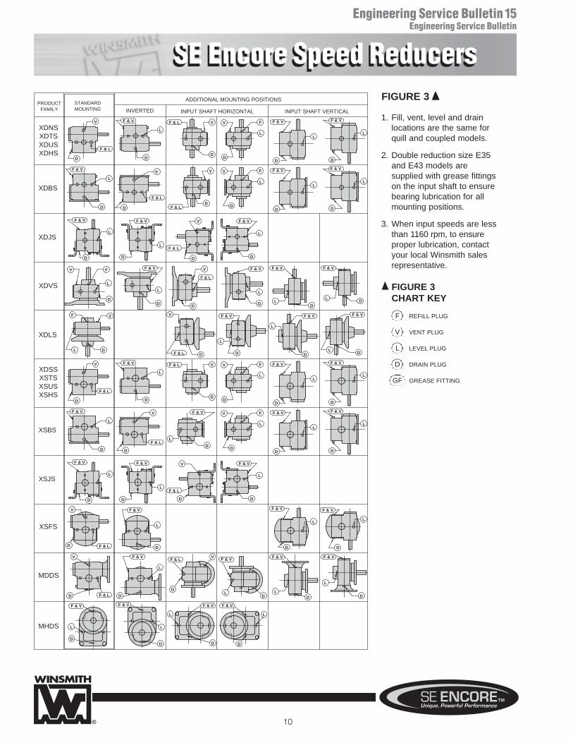
1. Fill, vent, level and drain locations are the same for quill and coupled models.
2. Double reduction size E35 and E43 models are supplied with grease fittings on the input shaft to ensure bearing lubrication for all mounting positions.
3. When input speeds are less than 1160 rpm, to ensureproper lubrication, contact your local Winsmith salesrepresentative.
REFILL PLUG
VENT PLUG
LEVEL PLUG
DRAIN PLUG
GREASE FITTING
F
V
L
D
GF
SE Encore Speed ReducersSE Encore Speed Reducers
Engineering Service Bulletin15Engineering Service Bulletin
11
FIGURE 4 CHART KEY
FIGURE 4
XSJX
XDJX
XSFX
XSBX
XDSXXSTXXSUXXSHX
XDLX
XDVX
XDBX
XDNXXDTXXDUXXDHX
XSFD
XSJD
XDSDXSTDXSUDXSHD
XSBD
XDLD
XDVD
XDJD
XDNDXDTDXDUDXDHD
XDBD
D
L
D
L
F
GFF
F
L
L
LD
D
D
F
L
GF
D
L
FGF
F
D
LL
L
DD
L
L
GFF
D
L
D
LF
D
L
L
D
F
D
L
F
D
L
D
FV
L
GF
DL
F
L
L
D
L
D
F
L
D
L
FGF
GF
D
L L
D
F
F
L
D
V
GF
D
L
F
L
LL
DD
FF & V
F & V
F & V
F & V
F & V
F & V
F & V
F & V
F & V F & V
F & V
F & V
F & V
F & V
F & V
F & V
DOUBLE REDUCTIONWORM/WORM
STANDARD MOUNTING
DOUBLE REDUCTIONHELICAL/WORM
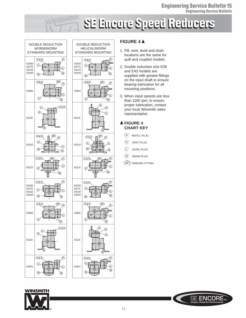
STANDARD MOUNTING 1. Fill, vent, level and drain locations are the same for quill and coupled models.
2. Double reduction size E35 and E43 models are supplied with grease fittings on the input shaft to ensure bearing lubrication for all mounting positions.
3. When input speeds are less than 1160 rpm, to ensureproper lubrication, contact your local Winsmith salesrepresentative.
REFILL PLUG
VENT PLUG
LEVEL PLUG
DRAIN PLUG
GREASE FITTING
F
V
L
D
GF
WarningsWinsmith products, and associated equipment and machinery, are intendedfor selection and use by trained and skilled persons capable of determiningtheir suitability for the specific application or use. Proper selection, installa-tion, operation and maintenance, including implementation of adequatesafety precautions, are the responsibility of the purchaser or user. The fol-lowing safety precautions, as well as additional safety precautions that maybe required for the specific application or use, are the responsibility of the purchaser or user. FAILURE TO OBSERVE REQUIRED SAFETYPRECAUTIONS COULD RESULT IN SERIOUS INJURY TO PERSONS OR PROPERTY OR OTHER LOSS.
Lock-out/Tag-outIt is EXTREMELY IMPORTANT that equipment or machinery does not unex-pectedly start. To prevent this possibility, all electrical or other input powersources must be turned off, and properly locked out. Tag out proceduresmust be followed before working on or near the reducer or any associatedequipment. Loads on the input and output shafts should be disconnectedprior to working on any reducer. Failure to observe these precautions mayresult in serious bodily injury and/or property damage.
GroundingBe sure the reducer and associated equipment are properly grounded and otherwise installed in accordance with all electrical code requirements.
Protective Guarding / Loose Clothing, etc.Always insure there is proper protective guarding over all rotating or movingparts. Never allow loose clothing, hair, jewelry and the like to be worn in thevicinity of rotating or moving parts or machinery. The purchaser or user isresponsible for complying with all applicable safety codes. Failure to do somay result in serious bodily injury and/or damage to property or other loss.
Selection & InstallationThis speed reducer and associated equipment must be selected, installed,adjusted and maintained by qualified personnel who are knowledgeableregarding all equipment in the system and the potential hazards involved.
Consult Catalog RatingsLoad, torque and other requirements must not exceed the published ratingsin the current catalog and/or on the speed reducer nameplate. The reducerselected must be consistent with all service factors for the application. SeeWinsmith catalogs and www.WINSMITH.com.
Brake Torque LoadsWhenever a brake or any other stopping force is involved in an application,braking torque loads imposed on the speed reducer must not exceed theallowable load ratings.
Not a BrakeSpeed reducers should never be used to provide the function of a fail safebrake or an assured self locking device. Speed reducers must never beused to replace a brake or a critical braking application function.
Excess Overhung LoadsExcessive overhung loads on the input or output shafts of a speed reducermay cause premature fatigue failures of the bearings and/or shafts. Mountgears, pulleys and sprockets as close to the housing as possible to mini-mize such loads. Do not exceed catalog ratings.
Excess Thrust LoadsExcessive thrust loads on the input or output shafts of a gear reducer maycause premature failure of bearings. Do not exceed catalog ratings.
AlignmentProperly align any input and output power transfer elements connected tothe speed reducer. Even slight misalignments in a rigid mounting systemmay cause binding, large vibration forces or excessive overhung loads, leading to premature bearing, shaft, or speed reducer failure. Use of flexiblecouplings that allow the reducer and connected transfer elements to self-align during operation will compensate for minor misalignments.
Not a Support StructureA speed reducer must never be used as an integral component of amachine superstructure or support frame that would subject it to additionalloads other than properly rated loads transmitted through the shafts.
Mounting PositionThe speed reducer should be mounted in one of the mounting positionsshown in the catalog. Different mounting positions should not be used without contacting Winsmith as this may result in improper lubrication.
Overhead MountingMounting of a speed reducer in overhead positions may be hazardous. Useof external support rails or structure is strongly recommended for any over-head mounting.
Lifting EyeboltsAny lifting supports or eyebolts provided on the speed reducer are suppliedwith the purpose of vertically lifting only the speed reducer, without any otherattachments or motors. Inspect such supports and bolts before each use.
Properly Secure Mounting BoltsProper mounting bolts and proper torques must be applied and maintainedto insure the speed reducer is securely mounted to the desired machinery.Inspect regularly as machine vibration may loosen fasteners.
Thread Locking CompoundProper thread locking compound should be appropriately applied to thecleaned threads of all mounting bolts connecting or securing the speedreducer to equipment and any drive, accessories, or brake componentsattached to the speed reducer. If, at any time after installation a factory supplied assembly or construction bolt is removed, care must be taken tothoroughly clean off the old thread locking compound and a new appropriatethread locking compound must be applied. Failure to properly apply newthread locking compound on all mounting or reducer construction bolts mayresult in serious injury or death from falling mechanical components.
Reducer Surface Is HotOperating speed reducers generate heat. Surface temperatures maybecome hot enough to cause severe burns. Proper personal protectiveequipment should be used.
NoiseOperating speed reducers may generate high noise levels. Use appropriatehearing protection and avoid extended exposure to high noise levels.
Lubricants Hot and Under PressureThe temperature of lubricants inside a speed reducer may be very high. Thereducer should be allowed to cool to ambient temperature before removal ofany vent, drain, level, or fill plugs, and before removing seals or bearing covers. Speed reducers without a pressure vent may also be under greatinternal pressure. Slowly loosen the lubricant fill plug above the lubricantlevel to vent any internal pressure before further disassembling.
Lubricant ContactContact with lubricants can present safety concerns. Proper personal pro-tective equipment should be used whenever handling speed reducer lubri-cants. Consult the lubricant MSDS sheet which is often available on thelubrication manufacturer’s website.
FDA, USDA, and NSF ApplicationsFactory supplied lubricants may not be suitable or safe for applicationsinvolving food, drugs and similar products. This includes applications subjectto FDA, USDA, NSF or other regulatory jurisdiction. Consult the lubricantsupplier or Winsmith for acceptable lubricants.
Inspection and LubricationEnsure proper operation by regularly inspecting the speed reducerand following all maintenance, operation and lubrication guidelines.
WARNING
Warnings And Cautions
172 EATON STREET, SPRINGVILLE, NY14141-1197PHONE: 716/592-9310 • FAX 716/592-9546WEBSITES: www.WINSMITH.com
PWS-198917 Printed in U.S.A.