engineering services guidelines - university of edinburgh · · 2015-05-115.3 microbiological...
TRANSCRIPT
Section 3: Mechanical Engineering Guidelines
Engineering Services Guidelines
Section 3: Mechanical Engineering Guidelines
The University of Edinburgh Estates and Buildings
Works Division
Issue: 4 Date: November 2014

Engineering Guidelines Issue 4 January 20014
Technical Services Group
The University of Edinburgh
http://www.docs.csg.ed.ac.uk/EstatesBuildings/Guidelines/EngineeringServices/Section3_Mechanical_Services.pdf
Page 2 of 17
Contents
3.0 Mechanical Engineering Guidelines
3.1 Design Criteria……………………………………………………………………. ..4
.
3.2 Heating Central Plant……………………………………………..……………...…5
3.3 Cooling Central Plant………………………………………………………………10
3.4 Pipework and Distribution …………………………….…………………………..10
3.5 Space Heating Equipment ………………………………………………………….12
3.6 Space Cooling Equipment ……………….………………………………….………13
3.7 Ventilation Systems…………..……………………………………………………....14
3.8 Water Hygiene ………………………………………………………………………15
.

Engineering Guidelines Issue 4 January 20014
Technical Services Group
The University of Edinburgh
http://www.docs.csg.ed.ac.uk/EstatesBuildings/Guidelines/EngineeringServices/Section3_Mechanical_Services.pdf
Page 3 of 17
Engineering Guidelines
1.0 General Introduction & Application
2.0 Testing and Commissioning
3.0 Mechanical Engineering Guidelines
3.1 Design Criteria
3.2 Heating Central Plant
3.3 Cooling Central Plant
3.4 Pipework and Distribution
3.5 Space Heating Equipment
3.6 Space Cooling Equipment
3.7 Ventilation Systems
3.8 Water Hygiene
4.0 Controls
5.0 Special Installations
5.1 Fume Cupboards
5.2 Lecture Theatres
5.3 Microbiological Safety Cabinet Ventilation
5.4 Liquid Nitrogen Installation
6.0 Electrical Engineering Guidelines
3.1 Design Criteria
3.2 Power Distribution Equipment and power quality equipment
3.3 Cable Installation
3.4 Lighting, Luminaries & Lamps and Lighting Controls
3.5 Fire Detection and Alarms
3.6 Emergency Lighting
3.7 Lightning Protection
3.8 Security and CCTV Installations
3.9 Telephone Installations
3.10 Data Installations
7.0 Lift Installations
8.0 Disability Discrimination Act (DDA)
9.0 Maintenance and handover procedures

Engineering Guidelines Issue 4 January 20014
Works Division
The University of Edinburgh
Page 4 of 17
3.0 Mechanical Engineering Guidelines
Any design must, as a matter of statute, be compliant with the Health and Safety at Work
etc. Act 1974, ANY relevant secondary legislation and associated Approved Codes of
Practice (ACOP’s)
Examples of secondary legislation include the Provision and Use of Work Equipment
Regulations 1998 (PUWER) the Workplace (Health, Safety and Welfare) Regulations 1992
the Electrical Safety at Work Regulations 1989 the Control of Major Accident Hazards
Regulations 1999 the Confined Spaces Regulations 1997 and the Gas Safety (Installation
and Use) Regulations 1998
Your attention is drawn in particular to the legal duties placed on designers by the
Construction (Design and Management) Regulations 2007
Suitable and sufficient safe access for maintenance and repair must always be provided
The following CIRIA guides should be used to inform your decisions, Construction work
sector guidance for designers (C662) Workplace “in-use” guidance for designers (C663) and
Construction work sector guidance for designers (C662D)
3.1 Design Criteria
The following design criteria are considered appropriate for the majority of projects and the
engineering services shall be designed in accordance with the following:
the requirements of the Project Brief.
the needs of the occupiers/users.
flexibility in use.
compliance with an agreed set of technical criteria
systems reliability, maintainability and cost in use
the requirements of the Health and Safety at Work Act
Designers must exercise care in ensuring that all operational requirements are met. Where the
University considers that it has relevant experience for specific installations, these are detailed
elsewhere in these guidelines.
Environmental Conditions The statistical design criteria for the Edinburgh area are:
i) Winter Dry Bulb - 5 degree C (see note 1)
ii) Winter Wet Bulb - 5 degree C
iii) Summer Dry Bulb 24 degree C
iv) Summer Wet Bulb 19 degree C
v) Diurnal Range 9 degree C
These design temperatures are exceeded on average 3% or 9 days per year over 20 years.
Note 1 – Where plant is expected to operate 24/7 under normal conditions the winter wet/dry bulb
temperature should be taken as -10 deg C
Internal Comfort Conditions There are a number of factors that influence the comfort of occupants within any environment
including;

The University of Edinburgh Engineering Services General Specification
Works Division Issue 3 June 2007
http://www.docs.csg.ed.ac.uk/EstatesBuildings/Guidelines/EngineeringServices/Section3_Mechanical_Services.pdf
Page 5 of 17
Temperature
Humidity
Air Movement
Odour/CO2 levels
Activity level
Noise
These must be considered against the variations between staff tasks, clothing level, age and fitness
level, awareness of external weather conditions and their expectations.
Designers are expected to comply with the comfort criteria as detailed in CIBSE Guide A, Table
1.1. The following is given as guidance.
Accommodation
Type
Internal
Winter
(deg. C)
Internal
Summer
(deg. C)(3)
Noise
(H&V
plant)
Min. Fresh air Rate (2)
Air Ch.
per hour
Litre/sec/
person
Seminar Rooms 21 26 NR 35 2 8
Lecture Theatres 21 26 NR 30 2 8
Cellular Office 21 26 NR 35 2 8
Open Plan Office 21 26 NR 40 2 8
Reception/ Entrance
Foyer
21 26 NR 40 2 8
Toilets 19 - NR 45 6 -
Laboratories (1) 21 26 NR 45 8 -
Conference Room 21 24 NR 30 4 8
Stores 16 - NR 45 - -
IT Equipment Room 18 27 NR 45 2 -
Computer Micro-lab 21 26 NR 40
Staff Mess Room 21 26 NR 35 2 8
Plant Room 10 35 NR 60 - -
Notes
(1) Consideration shall be given to reducing laboratory air change rates where proposed activity
permits.
(2) Minimum fresh air rates shall be determined by the greater of the two options. Where CO2
monitoring is utilised for control of fresh air, the control level shall be 1000 ppm.
(3) The internal summer temperatures shall not be exceeded on average 3% or 9 days per year over
20 years unless the requirements of the project dictate otherwise.
External Noise
Noise generation from engineering services within the building must not break out to cause
annoyance to either occupants or third parties or affect noise levels in adjacent buildings.

The University of Edinburgh Engineering Services General Specification
Works Division Issue 3 June 2007
http://www.docs.csg.ed.ac.uk/EstatesBuildings/Guidelines/EngineeringServices/Section3_Mechanical_Services.pdf
Page 6 of 17
Break-out from externally mounted plant or dedicated plant rooms must not, under any operating
conditions, exceed a background sound level of 58 dB A, (NR 50) at 3 metres from the plant or
plant-room.
Stand-by generators may be exempt subject to agreement from the Local Authority. It will be the
designer’s responsibility to ensure that all local planning conditions are complied with.
Heating and Cooling Control
Two port control and therefore variable flow will be the standard solution for control of heating and
cooling circuits. This is to achieve significant benefits in terms of energy and capital costs. It is
important to ensure that bypass routes are eliminated if maximum benefit for CHP and condensing
boiler installations are to be realised. Temperature differentials (delta t) in excess of 20 deg C in
heating circuits should be achieved under all but design conditions.
These circuits may be driven directly by differential pressure available from the district
heating/cooling systems or by variable speed pumps. Where variable speed pumps are used these
should incorporate constant differential pressure control, the setting for which to be determined
during the commissioning process. Pumps should be selected capable of 115% of the design flow
rate. Where appropriate, control valves should be polled to determine if pumps can be shut down.
If designed correctly a two port system should be effectively self-balancing and the design should
seek to minimise the number of commissioning stations, DRVs and other flow control devices.
The following should be considered:-
The application of reverse return pipe circuits.
The selection of pipe sizes to roughly balance the pressure drops.
The use of flow distribution manifolds to create equalised pressure drops across sub circuits.
The avoidance of terminal units with widely different pressure drops or heat emitting
characteristics.
Differential pressure control valves (DPCVs) should be used where control valves exceed 50mm
diameter to improve control at low loads.
3.2 Heating Central Plant
District Heating The following areas are served with LTHW from a district heating main;
Kings Buildings – whole campus
George Square – area around George Sq incl Teviot Row, Potterrow and the Medical
Buildings
Pollock Halls Residences – area served by north boiler house
Pleasance Energy Centre – includes Holyrood Campus, Pleasance, High school Yards and
Infirmary Street.
These systems are served by central combined heat and power plants as well as boilers.
The objectives of this approach are to maximise energy efficiency, minimise CO2 emissions,
provide for resilience, redundancy and to simplify maintenance. In order that energy efficiency is
maximised, this central equipment will be run such that the CHP operates as the lead heat provider.
Low return temperatures are critical for the efficient operation of CHP plant and circuit bypass
paths must be avoided.

The University of Edinburgh Engineering Services General Specification
Works Division Issue 3 June 2007
http://www.docs.csg.ed.ac.uk/EstatesBuildings/Guidelines/EngineeringServices/Section3_Mechanical_Services.pdf
Page 7 of 17
A single hot water network operated from the Energy Centre will service the heating requirement
for all buildings. At design conditions, this network will operate at 75 deg.C. flow and with a
differential pressure of 100 kPa at building entry.
Connection will be direct and through a standard design energy centre (see diagram Section 3.3
below) incorporating differential pressure control, automatic cut-off and energy metering. This
typically absorbs 20 kPa leaving 80 kPa for building circuits. The system will operate on a 24/7
basis and the flow temperature will be allowed to drop significantly (this is scheduled against
external temperature) when this is considered advantageous for CHP operation.
Heating systems shall be designed for a return temperature of 55 deg.C. maximum. All circuits shall
be variable flow with 2-port control (valve on return) to minimise flow rate and return temperature.
Space heating shall generally be by radiator and TRV on a variable temperature (VT) circuit. A
single VT circuit shall be provided per building with a single, sensorless VSD pump and 2-port
control valve in an injection circuit. Where other forms of heating are used it is essential that
control of water flow is by 2-port control without bypass. The use of low water temperature systems
is preferred.
Domestic hot water represents the only heating load to the CHP during summer months. These
should be of the storage calorifier type. Secondary circulation and primary control should have
separate time scheduling.
Boilers - General Heating systems should generally be gas fired and fully automatic in operation. Energy efficiency
and lifetime costs should be the guiding principles in the selection of system type and equipment
selection. Systems shall be designed with adequate provision to maintain suitable heat output in the
event of a failure of a single item of heating output. This will generally require a minimum of two
boilers rated at 66% of design load.
The preferred system will utilise direct boiler flow temperature modulation and maximum use of
condensing modes particularly within new build projects. Boiler selection should seek to achieve
class leading reduction in emissions and high overall efficiencies.
All plant and equipment shall be selected to operate within acceptable noise levels.
Cast-Iron Sectional Boilers Where boilers are supplied in sections, the manufacturer or his approved installer shall assemble
them on site. A protective casing and insulating jacket shall be provided.
Boilers shall be installed on purpose made stands or plates that ensure that irregularities in the base
do not interfere with the correct mating of the sections. Arrangements shall be made for positive
mixing to be induced within the boiler.
Modular Boilers Each module shall be identical and consist of cast iron sectional or finned copper tubes expanded
into cast iron or mild steel headers.
The modules shall be connected in parallel so that water from the common return header flows
through the modules to the common flow header.
Boiler casings shall be insulated and be provided with condensate drains.

The University of Edinburgh Engineering Services General Specification
Works Division Issue 3 June 2007
http://www.docs.csg.ed.ac.uk/EstatesBuildings/Guidelines/EngineeringServices/Section3_Mechanical_Services.pdf
Page 8 of 17
Water Heaters
Direct gas fired water heaters shall be all welded stainless steel construction. The burners shall be
matched to the individual flues and have an automatic ignition system. Controls shall be fully
automatic in operation and compatible with a BEMS system.
Plate Heat Exchangers Plate heat exchangers should be used in preference to storage calorifiers on DHWS wherever
possible. They should be used with storage buffer vessels to suit the particular circumstances.
Consideration should be given to summer/alternative supply via electric immersion heaters.
Where these units are installed in a building with a BEMS they shall be supplied as a basic unit
without a control panel, and the plate heat exchanger operation shall be controlled through the
BEMS system. A temperature sensor should be installed within the primary return pipe work to
control primary return water temperature
Fuel Installations
Installations shall be single fuel fired on natural gas unless indicated otherwise, and shall comply
fully with the current Gas Regulations.
Underground steel pipework shall not be used and gas pipe building entry shall generally be above
ground using proprietary PE to steel transition fittings to IGE/UP/2 Edition 3. At each entry to
plant rooms and kitchens, the gas supply shall be fitted with an automatic, electro-hydraulic
isolating valve.
Installations shall comply with IGEM/UP/16 “Design for Natural Gas Installations on industrial and
Commercial Premises with respect to Hazardous Area Classification and preparation of Risk
Assessments”
Any gas pipework in ducts, voids and enclosures inside and external to buildings should be avoided
where possible, and where required must be adequately ventilated.
General Conditions
On installations of two or more boilers, open to atmosphere, the open vent pipe from each boiler
may be connected into a common vent pipe through a three-way vent cock. This to be so arranged
that in no circumstances can any boiler be isolated simultaneously from the open vent pipe and
from the free outlet.
Boilers for LTHW systems shall include the following;
- One or two safety valves as required by the relevant BS.
- Open vent pipe on systems when they are open to atmosphere
- Altitude gauge.
- Temperature gauge.
- Emptying cocks or drain valves which are operated by removable handles.
- A nameplate giving:- Makers name; Series and type; Serial number; Rated output; Design
pressure; Date of manufacture.

The University of Edinburgh Engineering Services General Specification
Works Division Issue 3 June 2007
http://www.docs.csg.ed.ac.uk/EstatesBuildings/Guidelines/EngineeringServices/Section3_Mechanical_Services.pdf
Page 9 of 17
3.3 Cooling Plant
District Cooling
The following buildings around George Square are served by district cooling via underground
mains;
Main Library
George Square Theatre
Adam Ferguson Building
David Hume Tower
50 George Square
Appleton Tower
1 George Square
Robson Building
Wilkie Building
Medical Extension.
The full cooling system (commissioned 1st quarter 2007) is designed to maximise free cooling
during winter months and the use of an absorption chiller as part of a Trigeneration plant. The
chilled water flow temperature is scheduled against external temperature to achieve this.
Cooling systems must be selected and designed to operate with flow temperatures ranging from 14
deg. C. for external temperatures below 10 deg. C. (utilising free cooling) falling to 6 deg C for
external temperatures above 15 deg. C.
The strategy for district cooling is based on an expectation that the bulk of the cooling will be
achieved with chilled beams. These typically operate on chilled water flow-rates of 14 deg C and
provide opportunity for free cooling for much of the year. At design conditions, this network will
operate at 6 deg C flow and with a differential pressure of 100 kPa at building entry.
Connection will be direct and through a standard design energy centre (see diagram below)
incorporating differential pressure control, automatic cut-off and energy metering. This typically
absorbs 20 kPa leaving 80 kPa for building circuits. The system will operate on a 24/7 basis and the
flow temperature will be allowed to rise to 14 deg C (scheduled against external temperature) when
this is considered advantageous for free cooling operation.
Space cooling shall generally be by chilled beam on a (typically) 14 deg C flow and 17 deg C return
circuit. A single circuit shall be provided per building with two sensorless VSD pumps and 2-port
control valve in an injection circuit. Where other forms of cooling are used it is essential that
control of water flow be by 2-port control without bypass. The use of low water temperature
systems should be avoided, particularly where operation is required during periods of low external
temperature.
The provision of cooling to server rooms, IT hubs and freezer equipment rooms etc. where cooling
load would not be proportional to external temperature, should be selected with care. These areas
are also operational on a 24/7 basis and cooling equipment must be selected on the basis of 14 deg
C flow temperatures. Generally these areas should be provided with air supply to utilise local free
cooling.

The University of Edinburgh Engineering Services General Specification
Works Division Issue 3 June 2007
http://www.docs.csg.ed.ac.uk/EstatesBuildings/Guidelines/EngineeringServices/Section3_Mechanical_Services.pdf
Page 10 of 17
While acknowledging the increasing need to provide mechanical cooling to meet comfort and
operational cooling, all proposals for new and replacement installations shall be submitted to the
University’s Engineering Operations Manager for consideration.
Preference will normally be for chilled water from a modular unit. Central packaged chillers shall
generally utilise multiple screw compressors and designers shall require tenderers to identify the
COP at design conditions as part of the tender submission. Buffer vessels shall be provided to
minimise starts at low load conditions. BEMS control should include operational status, on/off and
temperature set point modulation.
Care must be taken to assess the effect of plant failure and maintenance on serviced areas, and any
necessary contingency provided. This risk assessment is particularly relevant to animal areas
and/or critical operational areas e.g. main computer server rooms, where the maintenance of
specified temperatures is either legislative or operationally required. Such considerations should
include 100% independent back up with auto changeover, remote alarm of high temperature and/or
plant changeover to a continuously manned monitoring position and UPS/standby electrical
generator.
Small areas or specific equipment requiring localised cooling may be served by DX split
equipment. These units should be monitored by the BMS system. Consideration of the
consequences of equipment failure is essential.
Internal condensing units whether using ducted air or not, will not normally be acceptable.
Wet cooling towers are not acceptable.
Pressure test points should be of the Binder type and are indicated above as + - they should be
fitted across strainers and system and building differential pressure.

The University of Edinburgh Engineering Services General Specification
Works Division Issue 3 June 2007
http://www.docs.csg.ed.ac.uk/EstatesBuildings/Guidelines/EngineeringServices/Section3_Mechanical_Services.pdf
Page 11 of 17
3.4 Pipework and Distribution
Pipework Generally
All pipelines shall be installed in a co-ordinated manner with routes parallel to the fabric of the
building. Where pipe-work passes through building fabric, it shall be sleeved by a single piece of
pipe of the same material as the pipe which it serves. All piped distribution services shall be colour
coded in accordance with BS 1710. Identification shall be minimum 25mm bands to pipework and
colour triangles to ductwork with indication of fluid flow direction.
MTHW, LTHW, Ch.WS and natural gas pipe-work shall generally be black mild steel, medium
(EN10255:2004), galvanised where appropriate, unless otherwise noted with flanged connections to
all connections above 50mm. Victaulic or similar systems will be permitted on main distribution
runs. Press-fit systems will not be permitted in steel pipework.
Where steel pipework is to be run below floors or is generally inaccessible, joints to be welded
regardless of pipe size.
Where copper pipework is to be used, this shall be to BS EN 1057:1996 with capillary or
compression joints up to 35mm dia. Press-fit systems will be permitted on domestic water systems
only provided that standard copper pipe is used. Otherwise, with capillary soldered joints up to
35mm dia., capillary brazed joints up to 54mm and flanged joints above 54mm dia.
All pipework shall be electrically bonded in accordance with BS 7671
Gas Pipework
All gas installations shall be installed in compliance with the current Gas Safety (Installation and
Use) Regulations;
IGEM/UP/2 Edition 3- Gas pipework in industrial and commercial premises
IGEM/UP/11 Gas pipework in educational establishments
IGEM/UP/16 Design for natural gas installations on industrial and commercial premiseswith
respect to hazardous area classification and preparation of risk assessments.
DSEAR Dangerous substances explosive atmospheres regulations.
Kitchen gas installations shall comply with;
BS6173 Specification for installation and maintenance of gas fired catering appliances for use
in all types of catering establishments (2nd and 3rd family gases)
IGEM/up/19 Design and application of interlock devices and associated systems used with gas
appliances in commercial catering establishments.
System schematics and all required labelling should be provided in a permanent and durable
format.
Gas supplies to all laboratories and teaching areas shall be provided with a gas soundness-proving
unit and a means of manual isolation in a prominent position within each laboratory or teaching
area.
Steam Pipework All steam pipe-work to be black mild steel, heavy (BS EN10255:2004), galvanised where
appropriate, unless otherwise noted with flanged connections above DN 50. At dismantling points

The University of Edinburgh Engineering Services General Specification
Works Division Issue 3 June 2007
http://www.docs.csg.ed.ac.uk/EstatesBuildings/Guidelines/EngineeringServices/Section3_Mechanical_Services.pdf
Page 12 of 17
and where pipework is connected to an appliance, bronze seated malleable iron unions shall be used
up to DN 50 and 3.5 bar. All other connections shall be flanged.
Condensate systems after the steam traps shall be in copper with joints made with compression
fittings to BS EN 1254 Parts 1 and 2 1998 or by brazing.
Pumping Equipment
Circulating pumps shall be designed for the flow rate and pressure drop of the circuit and shall be
suitable for the fluid, its pressure and temperature. All pumps shall be fitted with rubber flexible
connectors (to DIN 4809) on flow and return connections.
All circulating pumps shall be duplex (except DHWS secondary) operating as duty and standby
with automatic changeover on failure. Twin-head pumps should not be specified.
Circulating pumps will be variable speed, unless otherwise agreed with the University Engineer, to
maximise efficiency and life.
Valves etc.
Distribution pipework shall be run to falls and be fitted with all the appropriate isolating valves,
check valves, automatic air valves, drain cocks and strainers. Distribution pipe-work shall be so
constructed that systems can be fully cleaned and thoroughly flushed prior to setting to work.
Distribution systems shall be fitted with all necessary instrumentation. Pressure gauges shall be
100mm diameter, fitted with siphons and isolating cocks and with operating pressure at mid-scale.
Temperature gauges shall be 100mm diameter fitted in pockets with approved paste or oil.
Double regulating valves and commissioning sets shall be installed to permit commissioning and
setting to work of all parts of all systems apart from those which are served by central CHP or
Chilled water centres with variable speed pumps where discussion on commissioning shall take
place with the University Engineer. An isolating valve shall be positioned on the flow main
adjacent to each commissioning set.
Where control valves are fitted, ‘Y’ type strainers to be installed upstream for their protection.
Insulation
Thermal insulating materials shall comply with BS 5422:2009 and BS 5970:2012. Insulating
materials, adhesives, sealants and finishes shall be suitable in all respects for continuous use
without degradation throughout the range of operating and environmental temperatures. They shall
be selected to provide proof against rotting, mould, fungal growth and attack by vermin.
Within the building structure, insulating materials and their finishes shall comply with surface
classification Class O as defined within the building regulations.
Thermal insulation shall be applied to all supply and return LTHW pipework above ceilings, below
floors and in pipe boxes, ductwork and associated equipment used to convey heated or cooled air
within plant-rooms, unheated spaces, open air, fresh air ductwork in plant-rooms and unheated
spaces and to exhaust air ductwork in unheated spaces and the open air.
Where ducting or pipework is run external to buildings the thermal insulation to be suitably
protected against weather and, if necessary, vandalism, by methods to be agreed with the University
Engineer.
Insulation applied within plant-rooms shall be protected to prevent damage using 1mm thick,
hammer finish aluminium sheet
Valves, flanges and other fittings shall be fitted with removable, pre-formed insulated boxes.
Insulation to chilled water pipework shall be carefully formed with a continuous vapour barrier.
Insulation materials to have zero ODP.
3.5 Space Heating Equipment
The University of Edinburgh Engineering Services General Specification
Works Division Issue 3 June 2007
http://www.docs.csg.ed.ac.uk/EstatesBuildings/Guidelines/EngineeringServices/Section3_Mechanical_Services.pdf
Page 13 of 17
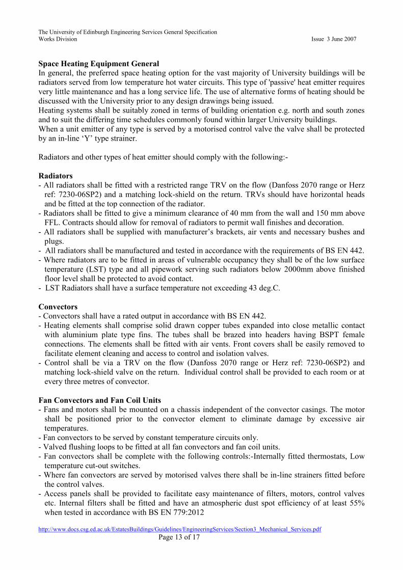
Space Heating Equipment General In general, the preferred space heating option for the vast majority of University buildings will be
radiators served from low temperature hot water circuits. This type of 'passive' heat emitter requires
very little maintenance and has a long service life. The use of alternative forms of heating should be
discussed with the University prior to any design drawings being issued.
Heating systems shall be suitably zoned in terms of building orientation e.g. north and south zones
and to suit the differing time schedules commonly found within larger University buildings.
When a unit emitter of any type is served by a motorised control valve the valve shall be protected
by an in-line ‘Y’ type strainer.
Radiators and other types of heat emitter should comply with the following:-
Radiators - All radiators shall be fitted with a restricted range TRV on the flow (Danfoss 2070 range or Herz
ref: 7230-06SP2) and a matching lock-shield on the return. TRVs should have horizontal heads
and be fitted at the top connection of the radiator.
- Radiators shall be fitted to give a minimum clearance of 40 mm from the wall and 150 mm above
FFL. Contracts should allow for removal of radiators to permit wall finishes and decoration.
- All radiators shall be supplied with manufacturer’s brackets, air vents and necessary bushes and
plugs.
- All radiators shall be manufactured and tested in accordance with the requirements of BS EN 442.
- Where radiators are to be fitted in areas of vulnerable occupancy they shall be of the low surface
temperature (LST) type and all pipework serving such radiators below 2000mm above finished
floor level shall be protected to avoid contact.
- LST Radiators shall have a surface temperature not exceeding 43 deg.C.
Convectors - Convectors shall have a rated output in accordance with BS EN 442.
- Heating elements shall comprise solid drawn copper tubes expanded into close metallic contact
with aluminium plate type fins. The tubes shall be brazed into headers having BSPT female
connections. The elements shall be fitted with air vents. Front covers shall be easily removed to
facilitate element cleaning and access to control and isolation valves.
- Control shall be via a TRV on the flow (Danfoss 2070 range or Herz ref: 7230-06SP2) and
matching lock-shield valve on the return. Individual control shall be provided to each room or at
every three metres of convector.
Fan Convectors and Fan Coil Units
- Fans and motors shall be mounted on a chassis independent of the convector casings. The motor
shall be positioned prior to the convector element to eliminate damage by excessive air
temperatures.
- Fan convectors to be served by constant temperature circuits only.
- Valved flushing loops to be fitted at all fan convectors and fan coil units.
- Fan convectors shall be complete with the following controls:-Internally fitted thermostats, Low
temperature cut-out switches.
- Where fan convectors are served by motorised valves there shall be in-line strainers fitted before
the control valves.
- Access panels shall be provided to facilitate easy maintenance of filters, motors, control valves
etc. Internal filters shall be fitted and have an atmospheric dust spot efficiency of at least 55%
when tested in accordance with BS EN 779:2012

The University of Edinburgh Engineering Services General Specification
Works Division Issue 3 June 2007
http://www.docs.csg.ed.ac.uk/EstatesBuildings/Guidelines/EngineeringServices/Section3_Mechanical_Services.pdf
Page 14 of 17
- Control valves shall be of 2-port type without bypass (variable flow) and interfaced to the BEMS
system
3.6 Space Cooling Equipment
Space Cooling Equipment General In general, full air conditioning or local cooling is not provided throughout the University Estate
where it is solely installed for the general comfort of individuals or group of individuals during the
'summer' period. This standard is to be applied to all new buildings or refurbishment undertaken by
external consultants.
The currently preferred method of space cooling is active chilled beam or ceilings, wherever
practical. Alternatively air based central plant should be considered. Ceiling mounted fan coils
should only be considered with the written approval of the Engineering Operations Manager.
Air conditioning or local cooling may only be installed if:-
it is required by regulation or enforceable code of practise e.g. Home Office Scientific
Procedures Act 1986 (see section 14.1).
there is a specific identifiable academic need (such as chemical deterioration at elevated
temperatures).
excessively high internal space temperatures are likely to be experienced.
there is no other practicable means of reducing heat gains. Practicable can include natural
ventilation, local ventilation, displacement ventilation, thermal store or passive solar measures
such as shading, orientation and high structural mass.
3.7 Ventilation Equipment
Air Handling Unit (AHU) An assembly of packaged plant components to provide treated air to ventilation systems. They
should be mounted in a plant room environment with adequate space for maintenance (external
locations only by prior agreement with the Engineering Operations Manager). All control functions
shall be undertaken directly by the BMS – AHU manufacturer controls will not be acceptable.
Each section shall be clearly labelled as to function.
Variable speed drives should be by stand-alone units should be fitted to all motors to permit areas
requiring ventilation to varying timescales and conditions from a single unit. Where appropriate, the
number of AHU’s should be minimised (e.g. combined) to minimise plant complexity and cost.
Motorised dampers shall generally be provided between ambient conditions and heater/cooler
batteries and controlled to “shut” when the ventilation is idle.
Where external intake grilles are at high level, provision should be made for access to the insect
screen from within the plant-room.
Valved flushing loops to be installed at all heater and cooler batteries.
Supply/Extract Fans Supply/extract fans with a duty in excess of 0.5 cu. m/sec shall be type tested to BS EN ISO5801
and BS EN ISO 5136 / BS EN ISO13347. Generally, ventilation fans should be centrifugal, of the
backward bladed type with a fan total efficiency of not less than 50%. Where fans are belt driven, a
minimum of two belts shall be used.

The University of Edinburgh Engineering Services General Specification
Works Division Issue 3 June 2007
http://www.docs.csg.ed.ac.uk/EstatesBuildings/Guidelines/EngineeringServices/Section3_Mechanical_Services.pdf
Page 15 of 17
Where appropriate, fans shall be controlled by inverter drives to maximise efficiency and plant life.
Supply and installation of the inverter shall be part of the BEMS contract.
Filters Supply air shall be filtered as specified in CIBSE Guide A Table 1.1. A set of spare filters shall be
provided under the contract and should only be fitted under direction of the University Engineer.
Panel Filters – air velocity at the filter face shall not exceed 1.75 m/sec. and manufactured to
standard sizes.
Bag Filters – air velocity at the filter face shall not exceed 2.5 m/sec. and manufactured to standard
sizes.
Filter condition indication shall be by magnahelic gauge, no BMS indication is required.
Humidifiers Selection of humidifiers shall ensure that hygiene is not compromised and that all risk from
legionella is removed. Where general humidification is required, an adiabatic evaporative type
humidifier, as manufactured by Condair (or an equivalent University approved unit) shall be used.
Adiabatic humidifiers shall be supplied complete with filters, pumps, staged control and a purpose
made control panel incorporating UV or chemical sterilisation. Care shall be exercised to ensure
maximum recommended face velocities within the humidifier are not exceeded.
Heat Reclaim Devices
The preferred device shall be a cross-plate exchanger with fully modulating bypass damper. Run-
around coils shall only be used in exceptional circumstances.
Ductwork and Terminal Devices General H&V ductwork shall be constructed from galvanised mild steel sheet or spriral wound for
small installations. The complete installation shall be in compliance with DW/144.
Fire Dampers with access doors shall be fitted to all penetrations of fire compartment partitions.
Flexible ductwork shall be used for connections to fans, grills and other terminal devices to a
maximum length of 1.5 metres.
Ductwork to/from commercial kitchen hoods shall conform to HVCA standard specification DW /
171.
3.8 Water Hygiene
Water can’t be entirely free from aquatic organisms, therefore, measures have to be taken to guard
against conditions that encourage microbial growth.
To reduce the risk of outbreaks the design of potable water systems should eliminate:
1) Direct contact of internal parts of pipes & structures by people, animals or birds.
2) Backflow of contaminated water into a system conveying potable water.
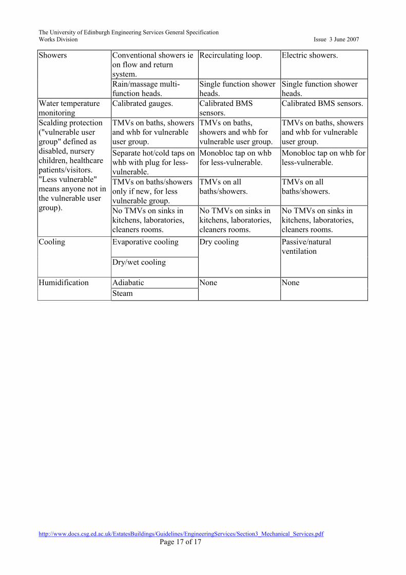
In order to avoid potentially costly remedial works, the design of new buildings and their water
systems is controlled in order to “get it right first time”. The RP provides the Projects/Design team
with a guide to ALARP (as low as reasonably practicable) which provides examples of design
preferences. This guide to ALARP is a matrix (see below). The guide is not a design brief and is not
intended to deal with all potential design issues.

The University of Edinburgh Engineering Services General Specification
Works Division Issue 3 June 2007
http://www.docs.csg.ed.ac.uk/EstatesBuildings/Guidelines/EngineeringServices/Section3_Mechanical_Services.pdf
Page 16 of 17
Hot & cold water supplies are considered potable. As such the design and installation of potable
hot and cold water services, and associated plant and equipment, in new, upgraded or refurbished
premises will comply with documents details below:-
[a] Scottish Water Byelaws 2004;
[b] BS8558:2011 Guide to the design, installation, testing and maintenance of services
supplying water for domestic use within buildings and their curtilages – Complementary
guidance to BS EN 806.
These documents detail the minimum standards for potable water storage for domestic use. For
example, the design of pipework should ensure no possible cross connection between installations
conveying potable and non-potable water or water from a private source.
The following document (held by Estates Maintenance/Project Staff) will be consulted for guidance
for the general design and operation of water systems on Trust premises:-
HSE Approved Code of Practice and Guidance Document [L8] – “Legionnaires’ disease: the
control of Legionella bacteria in water systems” and HSG274, Parts 1-3.
When new designs are produced, consideration is given to the impact of new technologies/
techniques and their impact on water consumption, e.g. the use of alcohol hand-rubs significantly
reducing the use of hand basin water supplies.
Yellow (Conventional
Practice)
Green (Good Practice) Blue (Best Practice)
Drinking water Stored mains water. Mains water. Mains water.
Cold water storage Single or multiple tanks
with conventional ball
valve(s).
Single tank with
delayed action inlet
valve.
No storage.
Water saving devices None. Fitted to existing with
attention to pipe sizing
eg fitted only in very
high use areas.
Fitted to new build or
major refurbishment.
Grey water (rain
water) systems
Present, with PPM,
labelling, UV treatment
with cartridge filtration,
transmission
detector/alarm, quartz
sleeve wiper mechanism.
Absent. Absent.
Small hot water
systems
Combi cylinder. Point of use water
heater.
Instantaneous water
heater.
Conventional domestic
cylinder.
Combi boiler.
Solar pre-heating
Large hot water
generation
Conventional calorifier. Plate heat exchanger
with buffer.
Plate heat exchanger.
Gas fired water heater
Vented or unvented
hot water.
Unvented with WRAS
approved cul-de-sac
diaphragm vessel.
Unvented with WRAS
approved flow-through
diaphragm vessel.
Unvented with WRAS
approved flow-through
diaphragm vessel.
Vented.
Large hot water
distribution
Single pipe. Flow and return
recirculating system.
Single pipe trace heating
The University of Edinburgh Engineering Services General Specification
Works Division Issue 3 June 2007
http://www.docs.csg.ed.ac.uk/EstatesBuildings/Guidelines/EngineeringServices/Section3_Mechanical_Services.pdf
Page 17 of 17
Showers Conventional showers ie
on flow and return
system.
Recirculating loop. Electric showers.
Rain/massage multi-
function heads.
Single function shower
heads.
Single function shower
heads.
Water temperature
monitoring
Calibrated gauges. Calibrated BMS
sensors.
Calibrated BMS sensors.
Scalding protection
("vulnerable user
group" defined as
disabled, nursery
children, healthcare
patients/visitors.
"Less vulnerable"
means anyone not in
the vulnerable user
group).
TMVs on baths, showers
and whb for vulnerable
user group.
TMVs on baths,
showers and whb for
vulnerable user group.
TMVs on baths, showers
and whb for vulnerable
user group.
Separate hot/cold taps on
whb with plug for less-
vulnerable.
Monobloc tap on whb
for less-vulnerable.
Monobloc tap on whb for
less-vulnerable.
TMVs on baths/showers
only if new, for less
vulnerable group.
TMVs on all
baths/showers.
TMVs on all
baths/showers.
No TMVs on sinks in
kitchens, laboratories,
cleaners rooms.
No TMVs on sinks in
kitchens, laboratories,
cleaners rooms.
No TMVs on sinks in
kitchens, laboratories,
cleaners rooms.
Cooling Evaporative cooling Dry cooling Passive/natural
ventilation
Dry/wet cooling
Humidification Adiabatic None None
Steam