‘engineering’ the software in systems
TRANSCRIPT

‘Engineering’ the software in systems by Derrick Morris, Peter Green and Richard Barker
The paper describes a method and notation for designing the software in embedded and other reactive systems. The design method is described in the context of a structured life-cycle, which recognises both functional and non-functional requirements, and it is illustrated by application to a substantial example. Mainly, for reasons of reuse and maintenance, an object-oriented solution is an implementation goal. The method focuses on producing s o h a r e fit for its intended purpose in terms of user functionality, while being concerned with other aspects of product quality. It also seeks to efficiently utilise the varied skills and experience in a project team, and assist the team in distributing and meeting responsibilities. Commercially available CASE tools are adapted to support the method.
1 Introduction
Today, software developers have to face not only the inher- ent difficulties of producing quality software [l], but also the plethora of methods, notations and tools currently on offer. This is against a background of ever-increasing com- plexity in the systems that are required, and pressure for better reliability and ‘time to market’ achievements. The demands are exacerbatedlincreased by the advances that have been made in the capabilities of micro-electronic technology, and by the apparent success of hardware col- leagues in improving their development process through the use of hardware specification languages, simulation, performance modelling and synthesis [2]. Thus, there is no escaping the need to improve the software engineering process, particularly in the way that it is applied to embed- ded systems.
Many methods, notations and tools are available, and difficult questions must be faced, such as which is the best method, how is it to be applied in practise, can the transi- tional costs be accommodated, and will the result be worth the effort and cost? We have had to face these questions as part of both teaching and research, particularly with respect to the software component of embedded systems. Although the term ‘embedded systems’ conveniently iden- tifies the market niche, the most significant features of
such systems from the developer’s perspective are that they are usually ‘reactive’ systems [3], they are developed by teams of mixed ability, skills and experience, and their designers have to operate in a constrained design space.
The approach to embedded system development dis- cussed in this paper results from the integration of a number of familiar concepts, notations and methods into a novel and coherent framework for analysis, design and implementation. By making extensive use of abstract models, it ensures that at each stage of development both functional and non-functional requirements are met, and it also provides a route into an implementation consistent with the model. Pragmatic goals include achieving a struc- ture that eases maintenance and creates reusable com- ponents. Throughout the paper, the method is illustrated by reference to an example system, described below.
2 System product example
The product example (Fig. 1) is a special-purpose oper- ating system (OS). Although not an embedded system, it is highly reactive and exhibits many of the same features and problems. Three other factors make it an appropriate choice for this work. First, there are few stated require- ments, and these can be understood without lengthy description. Secondly, the complexity of an OS is signifi- cant, and finally, the system has a substantial number of predetermined constraints. Thus, there is a clear need for applying two of the main features of the method, i.e. the evolution of system specification through models, and the development of a design subject to strong non-functional requirements.
Another reason for choosing this example concerns the relationship between OSs and embedded systems. Ideally, software for embedded systems should be written for a bare machine, to provide flexibility to optimise response times, to minimise the size of the software, and to integrate with application-specific hardware. However, this is a diffi- cult development route to follow, particularly as even mass-market products are now using sophisticated 32-bit microprocessors, and so real-time 0% are often used. An alternative under investigation is to create a library of (object-oriented) parts, from which a customised OS can be constructed. The chosen example is a first step in this direction, demonstrating that the notion and method make the use of a bare machine less formidable.
The specific example to be used to illustrate the method is a multi-user OS for a bus-based multi-processor system
Software Engineering Journal November 1995 253

operating system
kernel
V V Y
processor processor processor memory SCSl board 1 board 2 board 3 board board
VME bus
I/O board
/ )!I\
Fig. 1 Mapping operating system components onto hardware
that provides user access from dumb terminals, with pass- word protection. To reduce the example to a suitable size, it is assumed that it will be sufficient to run only pre- compiled application programs, such as word processors, expert systems etc., and so program development facilities need not be provided. Hence, a task shell may be per- manently allocated to each terminal, providing facilities for login and for the selection of application subsystems. These assumptions do not alter the key features that give the example relevance.
The initial product proposal is as follows. The interface required for applications should be a library of functions for basic input/output and file access. Program swapping and timesharing are to be as fast and unobtrusive as pos- sible. Type ahead is required on input, and sufficient output buffering must be provided to maintain full output rates despite timeslicing. Only programs that are ‘trusted’ will be used, and so the library functions may run in the user space rather than in protected OS space. Four ‘super- visor call’ functions are required: load and release applica- tion, suspend process (used when input is requested and there is none in the buffer, for example), and terminate, which terminates a session and causes a re-initialisation of the task shell.
The hardware is assumed to be a caged system, con- taining at least three single board computers (one with a memory management unit capable of supporting virtual memory), a shared memory board, a multi-channel serial communications board (providing interrupts) connected to dumb terminals, and an SCSI board (not providing interrupts) connected to a suitable disk. One processor manages the file system, while another controls input/ output, providing buffering in both directions. The third processor time-slices applications. Communication between software running on different processors is through shared memory. It will be seen later that this rather constraining, but not unrealistic, specification strongly influences the way in which the design develops, even from an early stage in the life-cycle.
3 Methods of analysis and design
One of the most heavily researched areas of software engineering over recent years concerns analysis and design methods, and it is appropriate to review this before deciding on the methods to be applied to the development of embedded and reactive systems. Two major categories of method merit particularly close examination. These’ are structured methods [4-61 and object-oriented methods [7-121. Many other methods have also been proposed [ 13, 141, but these are more specialised towards the develop ment of business information systems. Additionally, there is the Mascot (151 method, relevant because of its origins in the defence industries. This has not been considered here because it is less widely accepted and has lost ground to HOOD [lo]. Formal methods have also been widely researched, but currently their penetration into industrial practise, at a system level, is more sparse and usually exploratory, and so they are not considered further.
Another opinion that influenced our selection of poten- tial methods was that, regardless of other attributes, a method would not be suitable for embedded system pro- ducts unless it encouraged the use of abstract models of system behaviour, expressed in diagrammatic form. This is because such systems normally require a strong element of invention, the outcome of which is subject to review and agreement. From early in development, there is a need to produce and expose ideas. The popular view that a defini- tive requirement specification can be obtained through. the interrogation of customers breaks down with products that create new markets, or significantly broaden the applica- tion of existing products through upgrading. in these cases, there is a need to demonstrate new system propo- sals (at least through models) at a very early stage in the product life-cycle, in order to reach agreement on their suitability as a basis for further investment, and graphical models facilitate this better than text.
There is also wide agreement [ 161 that visual representa- tions of complex systems improve the capacity of engi-
254 Software Engineering Journal November 1995
neers to handle the complexity. However, it must be admitted that the requirement for a diagrammatic notation does not narrow the choice of method much, because most structured and object-oriented methods have this characteristic, although the features of some fulfil the underlying needs better than others.
3.1 Structured methods
The structured methods chosen for closer examination involve structured analysis (SA) followed by structured design (SD) [4] and specialised variants for real-time systems [5, 61 (RTSA). SA produces a behavioural model of a proposed system through functional decomposition and expresses it as a network of concurrent processes. After the SA model has been validated and approved, a SD is produced that models the implementation of the system as a hierarchy of sequentially executing modules. The need for the structural transformation from an approved behavioural model to a different implementation model, and the scope for error that this introduces, is a cause for serious concern [8]. Nevertheless, structured methods still have to be seriously considered for embed- ded systems because of the level of usage they have already achieved, partly through the availability of support- ing CASE tools such as Teamwork [lT]. However, it has become very clear that the weight of research opinion has turned away from structured methods and towards object- orientation, with some of leading proponents of structured methods [8] also moving in that direction.
3.2 Object-oriented methods
Arguments supporting object-oriented (00) software devel- opment appear in many publications, but their main thrust is consistent. 00 analysis is argued to be the most natural way to understand and model the problem domain, with real-world entities prompting the choice of objects on which the abstract system model can be based. Moving from analysis to design is also considered to be simpler when using 00 techniques, as it involves only incremental refinement and development rather than the creation of structurally different models.
The object concept, central to 00 approaches, may be briefly stated as follows. An object is a software module that presents a crisply defined interface, encapsulating data and associated functions (or methods) relating to an abstraction o f an application-relevant entity. As with abstract data types [18], the principle is that declarative statements are used to extend the basic type set of the language to include new types whose data can only be manipulated through specified functions.
The challenge in 00 analysis and design is how to dis- cover objects, and structure their class definitions, in a way that represents the best grouping of data and function. Clearly, in an information system, the primary purpose of many objects is to encapsulate the data that represents the attributes of application domain entities, and the func- tions will mainly provide controlled access to these attrib- utes. Suitable structures for many objects can therefore be discovered by entity analysis. However, in all systems there is a need for some objects that play a more active role, concerned, with implementing system strategies, for
example, and in practise the actual proportions of the dif- ferent kinds of objects vary according to the nature of the application. For example, in reactive (process-intensive) systems, the bias is towards objects that provide algorith- mically complex functions but contain little data. Entity analysis is not an adequate basis for object design in such systems, and alternative methods are needed, such as those based on the allocation of functional responsibilities to objects or ‘agents’ 1191.
Other proposals for dealing with reactive systems have considered the merger of the structured and 00 approaches, by using SA to front end an 00 result [20, 211. Part of the motivation for this derives from a desire to retain the best elements of a well tried and proven method (i.e. SA), but there is also a feeling that, in some applica- tions at least, analysis of the system’s functional behaviour is a legitimate ‘up-front’ issue. However, some workers [22, 231 consider the two approaches to be fundamentally incompatible, asserting that considerations of functional behaviour, applied at an early stage, will seriously deform the embryonic structure of a system.
Fortunately, there does at least appear to be a strong consensus that, whatever the initial approach, an 00 implementation is desirable. 00 programming can be demonstrated to yield a highly workable form of modular- ity, resulting in improved reliability, maintainability and the production of reusable software ‘parts’. The strong move- ment towards the 00 language C+ + is largely in recognition of these benefits. If only the change to 00 Analysis and Design was as clear cut.
3.3 Making a choice
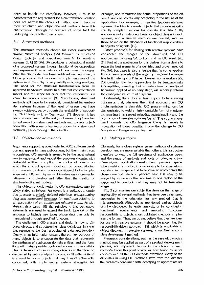
Obviously, for a given system, some methods of software development are more suitable than others. It is instructive therefore to view the full spectrum of application types, and the range of methods aud tools on offer, as a two- dimensional applicatioddevelopment process space. When making a choice, it is necessary to be clear where you stand in this space and to be clear at which points the chosen method needs to perform best. It is easy to be swayed by arguments that are true in one region of the space and to overlook that they may not be true else- where.
Fig. 2 summarises our subjective views on the range of applicability of several methods that have been examined (apologies to the originator for any method that is misrepresented). Although, as mentioned earlier, objects can be discovered by entity analysis, or by considering functional requirements and assigning functional responsibility to objects, most published methods empha- sise the former. Thus, we do not believe that they are ideal for use with reactive systems. It should be noted that the responsibility-driven approach [ 191, which is applicable to object discovery in reactive systems, is not itself a com- plete development method.
Pragmatic considerations, such as the ease with which a method may be applied as part of a product development process, are important factors in the choice of such methods. From this point of view, we have found cause for concern with all the 00 methods examined. Many of the difficulties in using 00 methods stem from the fact that the problems concerned with identifjmg an appropriate set
Software Engineering Journal November 1995 255

amtication
I data-in.-. ._. ._ .e e
Fig. 2
I
development process process-intensive
requirements requirements design code 8 test Capture analysis
Application/development-process space
of system objects are usually overwhelmed by the diffi- culties of constructing class definitions for the objects. This is typically done by producing hierarchical class definitions based on inheritance, so that not only is every object in the system an instance of one of these classes, but many of the class definitions are themselves built up by inheriting features from other classes. The concepts involved in gen- eralising class structures can be viewed as adding unnecessary complexity to the already formidable task of developing a complex reactive system.
It is reasonable to expect, therefore, that those with prac- tical experience in structured methods would prefer its more straightforward functional approach and will shy away from a sudden change to 00 methods, which requires them to leave behind all that is good in structured methods. However, it has to be admitted that even 'modern' structured methods [4-61 do not offer the same promise for reuse and maintainability as 00 methods, as it has to be agreed that abstractions based on functions are more volatile than those based on objects [7].
Thus, there is an attraction in seeking to evolve a method of producing an 00 design from the general structured methods approach, despite views that the two paradigms are incompatible [22]. These views appear to be the result of a conservative interpretation of SA seman- tics. For example, the notion that the purpose of a process is to transform data persists, and data flows are usually regarded as passive communications channels that do not trigger actions. Separate control mechanisms are used to start, stop and trigger processes, rather than using the idea of data-triggered processes. In addition, the potential to use data packets as a transport mechanism for com- mands has not been exploited; doing so enables pro- cesses to be regarded as command processors. We believe that, with a more liberal interpretation of SA semantics, it can be used to produce a suitable structure for object models of reactive systems. This being so, the final step of replacing process semantics by object seman- tics is simple compared with learning a totally new method. Others (20, 211 who have attempted to adapt SA have not taken the same liberties with its semantics.
These conclusions have prompted the development of the method described in this paper, which uses CASE tools intended for SA with additional conventions and
modified semantic rules. The development of models pro- ceeds via hierarchical decomposition, in a manner akin to SA. Models contain a context diagram which shows the system under development as a single object interacting with externals (e.g. devices, users, other systems). The system object is then decomposed into a set of interacting objects, which together provide the overall functionality of the system and define its architecture. Each object may then be incremental refined until the resulting set of objects are deemed to be primitiue, at which point textual specifications of the objects are produced. Thus, the method leads to a detailed specification of the 00 code to be written.
In order to ensure the large-scale applicability of the ideas embodied in the method, they are integrated into a comprehensive life-cycle, discussed in Section 5. The nota- tion used by the method is described below.
4 Modelling notation
Diagrams intended for SA are adapted to the role of docu- menting the models used throughout the proposed life- cycle, specifically state transition diagrams (STDs) and data-flow diagrams (DFDs). STDs are utilised to clarify aspects of system behaviour that are illustrated by intro- ducing a temporal partitioning of functionality. They rep resent the external behaviour of the system, observed by a user (Section 5.2), and also specify the behaviour of control objects, which are used to handle interrupts (Section 5.5). DFDs are more extensively used in two differ- ent non-standard ways discussed below.
4.1 Object interaction diagrams
The object hierarchy starts with a context diagram that shows the system to be developed as a single object ('bubble'), surrounded by the external entities (rectangles) that communicate with the system (Fig. 6). In the object interaction diagram (OID) hierarchy developed from this, each diagram represents a decomposition of an object at a higher level. The lines that connect each bubble are carried forward to the next level to become the lines that enter and leave the diagram (Fig. 7).
256 Software Engineering Journal November 1995

Three distinctive kinds of arrows are used on OIDs, rep resenting interactions, information floux and events. As the CASE tool only provides two kinds of lines, solid and dashed, interactions and information flows use solid lines and are distinguished by their labels as described below. Events use dashed lines.
Interaction lines represent message paths that carry requestlresponse pairs, the arrow showing the direction of the request, the response being implicit. When used on the context diagram of a user model (Section 5), they rep- resent the reactive aspects of required system behaviour. Within the system they represent messalges sent from one object to another requesting the execuljon of one of the receiving object’s operations. information flows are uni- directional and are semantically similar to data flows in SA. Their purpose is to represent the information flow between the objects in a system and its externals, and they should not exist between objects. Production and consumption of information by objects only take place when objects are active, which is normally when they are processing an interaction message or euent signals that represent hardware-generated signals (interrupts) and software traps. The responsibility for handling interrupts may be passed down the object hierarchy, but eventually resides in a special kind of primitive object, a control object, represent- ed by a dashed circle, and discussed in Section 5.5.
The hierarchical nature of the notation is intended to allow ‘large’ conceptual chunks of a system to appear as objects at the higher levels of the diagram hierarchy, and then be progressively refined into simpler objects on sub- ordinate (‘child) diagrams. There is also some advantage in placing a similar hierarchical structure on the connec- tions. For example, when there are several closely related operations, it is usually better to show them as a single line on the high-level diagrams, instead of individually. In addi- tion, when several interactions are necessary to complete a single logical transaction between objects, readability can be improved by postponing the presentation of this detail until later. Thus, the notation allows connections to be grouped into ‘bundles’, which are replaced at lower levels by their constituents.
4.2 Name and label conventions
All object symbols and connecting lines on OIDs are labelled with text to which the following ‘conventions apply. For primitive or library objects (see below), the text con- tains hhro names separated by a colon; the first name specifies the object’s class, and the second names the instance itself. Non-primitive objects are not given class names because the method does not require class defini- tions for them, but these may be synth’esised and named by a support tool. Repeated instances of a particular class must all have the same class name followed by a unique object name.
Labels on connecting lines are chosen to convey an impression of their purpose, and this is supported by con- ventions. For example, the name of an interaction, which specifies one of an object’s operations, is prefixed by the words GET, PUT or DO, depending on whether the oper-
I ation obtains or delivers data, or is algorithmically complex. Where appropriate, interaction names are also followed by parameter names in parentheses, which in
turn may be followed by \ and a result name($. Labels on interactions do not need to be unique, as their position on a diagram uniquely identifies them. However, this fails when several instances of one class occur on an OID and another object communicates with more than one of them, leading to ambiguity on the latter object’s OID. Thus, the labels of the appropriate interactions are pre- fixed with the object name to which they connect on the parent diagram.
Interaction and information flow names are written in lower case, whereas bundle names are written in upper case and have a dictionary entry (in the data dictionary provided by the CASE tool) which specifies the labels of the components, to which the above rules apply. Further conventions regarding the use of bundles are omitted in the interests of brevity.
4.3 Class implementation diagrams (CIDs)
The hierarchical decomposition of objects continues until objects are reached that are considered simple enough to be treated as primitiue. The class of each such object is then specified by a class implementation diagram. On these diagrams (Fig. 10) the ‘bubbles’ represent functions and data stores depict class state information. Functions may be public (e.g. DO.Suspend Task) or private, the latter supporting the implementation of the former (e.g. Get Next Task). Constructor functions (e.g. Scheduler) may also optionally be used. There will be a single interaction line entering the diagram for each of the class’s public func- tions, connecting to the appropriate function. Functions within a CID may call each other, with calls depicted by arrows between functions. If a constructor exists, it has the same name as the class and is automatically executed when instances objects of the class are created. Con- structors may have parameters which are enclosed in par- entheses. Objects that produce or consume information flows (not shown in Fig. 10) will have such flows leaving/ entering the CID and linking to the relevant function.
The specification of each object’s interface, which is all that should normally concern users of the class, is given in text linked to the CID. As the classes are intended to be reusable, the interface names must be appropriate to the abstraction represented by the class. These names may not be appropriate to any particular application. Thus, there is a further piece of text associated with each object that defines the mapping of its names into the equivalent class names.
Object models are complete once the textual specifi- cations of each CID function and data structure have been provided.
5 Proposed life-cycle
Before presenting the proposed embedded system soft- ware development life-cycle, it is useful to postulate a simple overall model of the project management structure in which it will operate. It is assumed that when a new product development begins, a senior engineer (the ‘Project Engineer’) will be appointed to lead the effort and will have overall technical responsibility for the project. They will shape the high-level structure of the product, based on systems engineering judgments that take
Software Engineering Journal November 1995 257

review and approve
review and agree - \ -
code detail a object-oriented implementation I
Fig. 3 Developmtrt life-cycle
account of all forms of requirements. Responsibility for more detailed development will then be allocated to specialist design teams. In a large project, the size of the team may require this kind of delegation at several levels.
5.1 Analysing product proposals
The first phase of the life-cycle (Fig. 3) is concerned with producing a set of structured requirements. Following the method of Esteal and Davies 1241, structured requirements are produced that distinguish between functional require- ments, non-functional requirements, design objectives and design decisions. The first of these set behavioural goals for the system, and the others constrain the design space in which its designers operate. Clear recognition and con- firmation of these constraints can be as important in launching a successful product development as approving its functional definition. However, the opposite view is often presented, curiously enough for the same motives, i.e. ‘to avoid (wrong) decisions being taken by the wrong person
Do ServiceReauest (service)
services availab!e
application commands
application information
at the wrong time’ [4, 241. The apparent contradiction arises because embedded system software is only one part of a larger product, and consideration of the system as a whole inevitably leads to restrictions on the software designer’s options, whereas in a large information system project, an unconstrained logical model is needed to set the scene for all implementation decisions.
5.2 Constructing the user model
The next phase of the life-cycle involves the creation of a user model. As in SA [4], this is an abstracted view of the system, based on functional requirements only, and it pro- vides an external view of how the system is to behave. Clearly embedded system software may affect end users indirectly through other system components whose behav- iour has been decided elsewhere. Thus, fine judgments are necessary to achieve a model that will satisfy the dual requirements of providing a basis for agreement on system behaviour, from a purely user perspective, and defining the overall functionality goals to be met in the subsequent ‘systems engineering’ phase.
The user model is a formalised deliverable of the life- cycle, in recognition of the fact that in speculative or inno vative developments the initial product proposal is likely to be incomplete and even flawed, and appropriate clari- fication and assumptions are necessary to achieve consis- tency and completeness. As with the non-functional requirements, interaction is required with those responsible for the initial product proposal and its expected market, in order to gain agreement. Both the notation and style of the model, and indeed other models used later in the life-cycle, are critical to the efficiency of these human interactions.
The user model for the example is documented by a system context diagram (Fig. 4), a behaviour diagram (Fig. 5), which is an STD, and supporting text. In effect, the user model structures and clarifies the functional requirements. For example, the communication lines on the context diagram provide a logical classification of the total inter- face, and the behaviour diagram provides temporal par- titioning of the system functionality. In both cases, clarification and detail are conveyed by associated text. As indicated in Section 4.2, there is a textual definition for bundles that describes their constituent parts. Thus, the bundle Supervisor Calls would be defined to be Suspend- Task, TerminateTask, LoadApplication and ReleaseAppli- cation. The text associated with each state of the behaviour diagram (not included here) will define the required behav- iour of the system while in that state.
5.3 Systems engineering phase
The phase that follows agreement on the user model/ structured requirements is where the critical ‘systems
operating system
IO-commands
supervisor calls
file-commands
application program
Fig. 4 User model context diagram
258 Software Engineering Journal November 1995 i

I power up
initialising task shell
initialisation complete
I display services
inviting login
'terminate' issued I I correct nameipassword
initialise task shell given
application services
application selected release application
I load application
behaviour in I C 1
10 command issued - this state *command performed
10 command
next time slice 10 not available I I
waiting next tlme slice
disk required I transfer complete
request transfer
polling i for completion
Fig. 5 Users view of system behaviour
engineering' judgments of the project engineer are con- centrated. Its purpose is to create, evaluate and gain approval for an architecture model, which defines the major software components (primary objects) of the system and how they are to interact. It is also appropriate at this stage to consider and agree test plans and accep- tance criteria, and these would be added to the structured requirements. However, this aspect is not developed further here.
Although the notation presented ih Section 4 provides for hierarchical definition of objects, normally the hierarchy will be quite shallow at the architecture stage. A new context diagram starts the hierarchy that subsumes the functionality specified in the user model, with the addi-
memory manager
unit . . MM-event
\ \
tional purpose of defining the context in which the software is to operate. Thus, relevant special features of the machine(s) or virtual machine(s) that will execute the soft- ware must be shown. If suitable library software is available to deal with these physical aspects, then the library objects may be shown as the externals. In either case, the logical command interface of the user model has to be replaced by the mechanisms through which the software will receive the commands.
The detailed differences between the two context dia- grams can be seen by comparing Figs. 4 and 6. The dashed lines in Fig. 6 represent the interrupts that the soft- ware must handle. Clearly, if an OS kernel is to be used (not the intention here), the interrupts would be its
I clock I /
/ /
/ /
pulse / \
PUTSetSegment- ', / /
/
operating system PUTSCSI-Cmnd IO-Interrupt - - - -
/
PUTSCSI Data-
SCSl controller
/ /
PUT Register- Value (value) out
Fig. 6 Architecture context diagram
Software Engineering Journal November 1995 259

responsibility and would not appear on the context diagram. Instead the kernel would be shown as an exter- nal, connecting with the system through the relevant com- mands.
In effect, the purpose of the diagrams that follow the context diagram is to decompose the system into its Primary Objects and to establish their responsibilities, which begs the question ‘how are the functional responsibilities decided?’. Although the following guide- lines do not provide a complete answer, we have found them helpful.
0 Invent objects to serve as ‘agents’ with clear functional responsibilities [ 19). 0 Assign to separate objects functions that will have real or quasi-concurrency. 0 Ensure that there is strong cohesion for functions assigned to an object. 0 Minimise the spread of responsibility for implementing action($ associated with a single system state (as defined in the user model). e Hierarchically decompose complex objects, stopping at a level that leaves maximum flexibility for the design to develop according to best software engineering practise, but 0 ensure that the level of decomposition is sufficient to support some worst case timing analysis relating to event response times and information throughput. 0 Show whatever detail is necessary to allow the specifi- cation of strategies that the project engineer deems critical to meeting objectives.
Figs. 7, 8a and 8b show the primary objects of the OS, and thereby complete the graphical part of the architec- ture model. The distribution of responsibility between primary objects of the OS is now briefly considered.
Responsibility for input/output buffering strategies rests with the communication channels object, and those for disk management with the disk system object. For both objects, the project engineer would probably impose per- formance constraints and would have a choice relating to the rigour of the functional specification. For example, operations could be fully specified or they may be left open for the present, which means that the authority to decide the best interface is delegated to the implementors of the objects. Where a specification is given, it is in the text associated with the object and/or the communication lines that enter it.
The disk command buffers and I/O buffers objects are interesting because they will be used by software running in two separate processors that communicate through shared memory, and these objects encapsulate the proto- col that controls the communication. In the actual imple- mentation, two instances of each object will be compiled, one into the software of each separate computer, but in the model their full responsibility is best defined by using one object.
The most complex object on Fig. 7 is the user task domain, and this leads to its functional decomposition (Fig. 822) being treated as part of the architecture.
After the functional responsibilities of the primary objects have been allocated and documented in text linked to the object symbols on the diagram, appropriate con-
straints are added. These are decided according to the project engineer’s interpretation of the structured require- ments for the whole system, with the goal that if every object satisfies its constraints, those of the total system will be satisfied. Usually the project engineer will have only pre- vious experience to guide the allocation of constraints, and decisions may sometimes have to be revised. However, clear documentation of constraints, even though they may be reviewed on the basis of later feedback from the design team, provide the project engineer with control over system issues that are often left to chance.
This feature of the life-cycle does, however, require that the project engineer’s experience is sufficient to justify the prerogative to constrain the design space in which other team members operate. Of course, in practise the archi- tecture is likely to be the result of a collaborative effort of senior members of the team, perhaps guided by the results of design studies and experiments. For example, if the architecture model is particularly complex, it is likely that the project engineer would commission analysis of critical system issues and possibly experiments, in order to build confidence that all non-functional requirements can be met when the further decomposition of primary objects is delegated. Reviews of the architecture based on ‘what-if scenarios might also be used to establish that the function- al requirements are met. The notation of the model is intended to support and control such investigations. When the studies are complete, the architecture will be ‘signed off, in the expectation that it firmly lays down the terms of reference for the further development of the primary objects.
5.4 Developing the hierarchical object model
Fig. 3 shows that there are two further stages in the life- cycle, after an architecture is produced and before the detailed coding begins. In the first of these stages a full hierarchical object model is produced, by continuing the decomposition of primary objects down to objects deemed simple enough to be treated as primitive. Both functional requirements and constraints are passed down this hierar- chical model, so that at each level the designer’s job is a specified and constrained task. During this stage, the reuse of previously defined objects (from a library) may be con- sidered and potentially reusable objects may be invented. Once the object hierarchy has been completed, all the parts (and sub-assemblies) needed to construct the system have been specified. At the lowest level of the hierarchy, class interaction diagrams (CIDs) are used to specify the behaviour and data content of the primitive objects, as indicated in Section 4.3.
Up to this stage, a designer experienced in structured methods should not have the feeling of being on unfamil- iar ground, provided that the requirement for good abstraction and strong encapsulation of detail by objects can be achieved. However, questions arise relating to the dynamics of the model. At this stage of the life-cycle they are similar to those of a SA model; the model is one of potentially concurrent objects, and those with no mes- sages to process or events requiring responses will be ‘busy waiting’. Behaviour of the model can be appraised by considering only the functions contained on the ClDs of
260 Software Engineering Journal November 1995

f I MM-Event
\ ’ PUT.SetSegment- \ Pointer[seament)
pulse
k
f \ \
f PUT.SCSI-Data-
In
system communication
channels
(channel)\char Complete GET.FILE- PUT.SCSl-Cmnd REQUEST Value\value PUT.Register-
Value(value) J Fig. 7 Architecture decomposition
the primitive objects, as the behaviour of the hierarchy is equivalent to that of ‘flattened’ network that results from substituting the OID for each non-primitive object in the hierarchy and the CID for each primitive object. Messages sent to functions are assumed to be automatically queued if necessary, and communication is synchronous, with a sending function always waiting for a response from the receiver. Obviously these dynamics are not exactly those of 00 languages, and this is one issue that is dealt with later in the life-cycle when the hierarchical model is transformed into an implementation model.
Research yet to be published has shown that the dynamics of hierarchical models can be investigated through interpretive execution, provided that suitable textual definitions are created for the operations of primi- tive objects. Executable models can be used to validate behaviour, explore performance, and later on, provide a test harness for implemented objects.
5.5 Developing the implementation model
The concurrency of the hierarchical object model will be restricted in the implementation according to whether the system is multi-processor or multi-tasking in nature, or is interrupt-driven. Objects that execute in a single task of a single processor will process their messages on the thread of execution of the senders. For software intended to be independent of OS support, the number of processors and the use of interrupts determine the number of threads of execution to be considered. Thus, the actual concurrency level of the implementation must be shown on the model so that it may be critically examined to ensure that dead- locks cannot occur, and that the integrity of the state infor- mation contained in the objects cannot be compromised. Another effect of the changes made to the model at this stage is that the low-level interface to hardware becomes
the responsibility of control objects, and none of the other objects need to be concerned with events and state changes in the processor. A corresponding approach can be developed to handle the task threads if a standard OS kernel is to be used in the system.
A control object is introduced into the OID hierarchy for each processor in the implementation. Other related changes are that events to be implemented as interrupts in a processor are re-routed through its control object. In a similar way, interactions between objects that imply a state change in the processor, for example between user level and ‘supervisor mode’, are also sent through the control object. Fig. 8b is a revision of Fig. 8a, showing the addi- tion of a control object and application of the above trans- formations.
The semantics of a model with control objects are that at power up only the control objects become active. Each control object may be ‘busy wait’, in which case other objects can only become active as a result of interrupts, or it may activate another object by sending it a message, thereby passing the thread of execution. When an interrupt occurs, the main thread of execution is paused and another message from the control object (taking with it the new thread of execution) activates the object(s) responsible for servicing the interrupt. This thread eventually returns to the control object, through the normal function return mechanism, where it terminates, allowing the main thread to resume.
A second transformation of the object model during this phase results from a review of the class structure specified by the CIDs. Here the full complexity of the 00 philosophy can be applied, and ‘kind of class hierarchies can be developed to produce the required class definitions. However, the amount of work and the skill level required are substantial, and the main benefit is in situations where there is potential for reuse. We have usually stopped short of this level of generalisation-specialisation elegance.
Software Engineering Journal November 1995 26 1

DO SuspendTask \ I \ I
\ I pulse MM Event
DO Release Application shell
2 DO TerminateTask
DO IsTranComplete DO StartPage
Transfer system
GET Inputchar PUTOutputChar- PUT FILE- GET FILE (channel)\char (channel, char) RESPONSE
J
b Fig. 8 a User task domain OID; b user task domain OID (incorporating control object)
Instead we normally produce the CID for each primitive object and then construct its class definition, making only sparse, ad hoc use of inheritance. We realise that this will be considered to be an object-based, rather than an 00, solution which in principle could be more elegant, and some of our current research is concerned with methods for specifying inheritance on CIDs.
5.6 Route to the source code
The issues involved in translating the implementation model into source code are now considered. In order to be specific, C + + is taken as the target language.
When coding an implementation model in C+ +, a number of problems arise associated with the way in which the hierarchy is represented and how reusable objects may be produced. A simple structure that completely avoids representing the hierarchy implements the system as if it were a flat network of primitive objects at the base level of the hierarchy. This requires a class definition for each primitive object at the start of the code and the declaration of instances of all the required objects at the head of the main program unit. In this structure, direct references (by name) to other objects are needed in the definitions of the operations. Although this solution is simple, it interferes with the reuse of the class definitions due to the embed-
262 Software Engineering Journal November 1995

ding of application-specific names in code for the member functions.
An alternative solution is to include pointers to objects whose methods are used, within the state space of a calling object, although additional member functions are then required to initialise these pointers at run time. This approach has the advantage that it can also be applied to the creation of class definitions for the nonprimitive objects throughout the hierarchy, although doing so can be tedious. However, the task is a deterministic one and as such can be automated, thereby synthesising a skeleton of all the class definitions for both primitive and non-primitive objects. These will contain declarations of pointers to the class types used, definitions of pointer initialisation func- tions, and in the case of classes representing non-primitive objects, instances of primitive objects or other non- primitive objects. The constructors of non-primitive classes will also require calls to the pointer initialisation functions.
6 OSmodel
Selected parts of the OS model have already been intro- duced that illustrate the notation and some of the stages of the method. In this section we aim to use the model to highlight the principal virtues of the method through a dis- cussion of the parts already presented, and by developing additional elements of the OS model,
Figs. 4 and 5, which depict part of the user model, clearly show the external view of the system in a form that is simple and easy to understand, features which are sig nificant if the user model is to form an appropriate vehicle for communication between customers and developers. The architecture context diagram shown in Fig. 6 is a development of Fig. 4, which indicates how the logical interactions between the system and its environment are to be realised. This two-stage procedure is important in that it
enables the logic of the required interactions to be estab- lished before considering their implementation, achieving a valuable separation of concerns. Once complete, the architecture context diagram rigorously defines the system’s interface to its environment. Fig. 6 also illustrates that, although the notation is simple, it is rich enough to describe the range of possible interactions between an embedded system and its hardware environment.
Hierarchical decomposition is illustrated by Figs. 7, 8a and 9, which demonstrate how a simple structure, con- forming to good 00 practice, can be obtained with the help of the guidelines presented in Section 5.3, particularly with respect to functional responsibility, concurrency, and the partitioning of states in the behaviour diagram (Fig. 5).
Comparing Figs 8a and b again shows how the method enables the logical structure of the system to be estab- lished, and how details of interactions with hardware can be introduced into the model and isolated from the system’s objects through the use of a control object.
It is not our intention to include the rest of the OS model, as it is much too large to present in this paper. However, the OS kernel has been chosen for further decomposition, as it demonstrates a number of additional features of the method. The decomposition of this object is shown in Fig. 9. The main criterion for choosing this decomposition was to cleanly separate responsibilities associated with tangible entities. Thus, objects are responsible for managing the virtual memory, scheduling tasks and controlling the allocation of RAM. The interfaces of these objects are established by considering both the services each object provides to its clients and also the facilities that each object requires. Careful choice of the latter is just as important as the former, a point that some other methods do not recognise.
Consider, for example, the VM manager object in Fig. 9. I t s main responsibilities are to initialise and reset the virtual memories, to load and release applications and service
Fig. 9 os
DO.ResetTaskShell DO.Release-
DO.ResetTaskShell Application
DOServiceVM-lnt
I shell:
manager / DO.AllocateBlock
DO.UpdateTaskTime
virtual memory :VM
manager timer :timer
DO.Start Page- Transfer
PUTSetSegment- Pointer(segment)
RAM;RAM manager
DO.SetTimeLimit- (time-limit)
- DO.SuspendTask scheduler
4
kernel OID
\ DOServiceVM-lnt DO. Load-
Application shell:
manager / DO.AllocateBlock
DO.UpdateTaskTime
virtual memory :VM
manager timer :timer
DO.Start Page- Transfer
PUTSetSegment- Pointer(segment)
RAM;RAM manager
DO.SetTimeLimit- (time-limit)
- DO.SuspendTask scheduler
4
kernel OID
Software Engineering Journal November 1995 263

virtual memory interrupts. In addition, it has a method (DO.PeriodicCheck) through which it is periodically activat- ed in case it needs to carry out timed actions. Responsibility for calling this method is assigned to the control object on Fig. 8b because it receives timer events. Another instance of anticipating a need is seen in Fig. 9, in the passing of information from the VM object to the task scheduler (PUT DiskWait) that relates to tasks held up waiting for disk transfers to complete. The task scheduler may choose to act on this information or not according to what seems to be the best strategy, but if the information was not passed, it would not have the choice. In a similar way, the VM object can choose from a wide range of stra- tegies how best to deal with VM interrupts, the simplest being to treat them as faults, but this, of course, has impli- cations on the definition of the virtual store facility.
We assert that this kind of generalisation of object inter- faces that provide flexibility for determining implementa- tion strategies inside objects can only be achieved in a design method strongly biased towards identification of functional responsibilities. It is most relevant if the long term intention is to build up libraries of reusable objects and, in the case of some objects, to offer several interface- compatible implementations of varying internal complex- ity.
Fig. 10 illustrates the class structure of the primitive task scheduler object, showing how the operations of the class affect the state of instances and how the operations inter- act with each other. It is evident that, by providing such a detailed class specification, the skeleton structure of the class, and indeed the whole system, can be synthesised from the model.
7 Experience in applying the method
We have constructed several models for products, such as video cassette recorders and PABXs, in order to assess the method and notation. Evaluation has also taken place in
an undergraduate software engineering laboratory. This is attended by second-year students and provides their first experience of complex software design. Previously, SA, SD and C were used in the laboratory, and the 00 method described in this paper has provided a satisfactory alterna- tive that provides experience in C + + . The students work in teams of five or six and are initially given a loose require- ments specification for an embedded system, from which they deduce a set of structured requirements. These are used to guide the construction of a hierarchical object model and CIDs, leading finally to an implementation in c+ +.
AI1 the projects involve some level of concurrency and low-level device handling, and so provide a reasonably challenging test of the method’s applicability. Project time- scales are very tight (12 weeks from start to finish), provid- ing little room for many iterations of the model before it is frozen for implementation.
Of the projects undertaken so far, all of the groups have been able to apply the method, with resulting implementa- tions which varied from fully integrated working systems to those where the primary objects had been implemented and successfully tested but not integrated.
Comparisons made with previous years in which SASD and C have been used show an improvement in program structure. There is now little global state information, the grouping of data and function demonstrates better cohe- sion, and system components are more loosely coupled.
The experience of the students in the design laboratory leads us to be optimistic about the applicability of the method, the feasibility of learning it, the cost of developing systems and the quality of the software that results. In addi- tion, our own work convinces us that it can be scaled up to industrial-sized problems. The students’ designs show how the method allows issues of low-level interfacing and con- currency to be handled in a simple and comprehensible manner, and enables constraints to be propagated through the design so that the developer can assess whether the resulting implementations actually meet the associated constraints.
\ I PUT DiskWait PUT DiskFree 1
DO TimeOut
(time-limit) - Y (task-no)
DO GetNextTask\- DO ChangeContext- (task no)
(time-limit)
\ DO.GetNextTask\. task-no, time-limit
Fig. 10 Task scheduler CID
264 Software Engineering Journal November 1995

8 Conclusions
In this paper, we set out to convey what we have learnt from our attempts to establish a process for engineering the software in reactive systems. A full life-cycle has been proposed, together with a notation supported by an impro- vised CASE tool. The graphical models facilitated by the notation are central to the operation of the life-cycle, and form the primary means by which non-functional consider- ations influence design decisions and ensure that the final product meets all its requirements. They also aid design validation. There is sufficient detail in the models for them to be executable, and this feature can be exploited for investigating design options, validating choice and finally testing an implementation.
Although we concede that many methods have a broad range of applicability, and indeed the method presented here may be applicable to systems that would not be clas- sified as reactive, it is reactive systems, and in particular embedded systems, that we have tailored the approach towards. Such systems are of growing importance, and we believe that other methods, unlike the approach proposed here, have not fully recognised some of the important issues which seriously affect embedded system develop ment, such as early treatment of non-functional require- ments, analysis of functional responsibility and the implications of reusable libraries.
We chose to base the notation on a concept of objects that map into class definitions in C+ +. The main reason was to obtain the recognised benefits of 00 methods: the clarity of understanding that comes from abstraction, the safety of implementation that comes from encapsulation, and the potential for reuse. From our experiences of both teaching and using the approach, we believe that it works well. Based on this, we are currently directing effort into extending the method to form a total systems approach to hardware/software codesign and the construction of tools to support it.
9 References
[I] PARNAS, D.L.: ‘Software aspects of strategic defence systems’, Commun. ACM, 1985, 28, (12), p. 1326
[2] MCFARLAND, M.C., PARKER, AC., and CAMPASANO, R.C.: ‘The high-level synthesis of digital systems’, Proc. I€€€,
[3] HAREL, D.: ‘STATECHARTS: a visual formalism for complex systems’, Sci. Comput. Progr., 1987, 8, p. 231
[4] YOURDON, E. : ‘Modern structured analysis’ (Prentice-Hall, Inc. Englewood Cliffs, New Jersey, 1989)
[5] WARD, P., and MELLOR, S.: ‘Structured development for real-time systems’ (Prentice-Hall, Inc., Englewood Cliffs, New Jersey, 1985)
[6] HATLEY, D., and PIRBHAI, I.: ‘Strategies for real-time system specification’ (Dorset House, New York, 1987)
1990,78, pp. 301-35
[7] BOOCH, G.: ‘Object-oriented design with applications’ (BenjamidCummings Publishing Company, Inc., Redwood City, California, 1994) 2nd edn.
[8] COAD, P., and YOURDON, E.: ‘Object-oriented analysis’ (Prentice-Hall, Inc. Englewood Cliffs, New Jersey, 1991) 2nd edn.
191 RUMBAUGH, J., BLAHA, M., PREMERIANI, W., EDDY, F., and LORENSEN, W. : ‘Object-oriented modelling and design’ (Prentice-Hall, Inc. Englewood Cliffs, New Jersey, 1991)
[ 101 ROBINSON, P.J. : ‘Hierarchical 00 design’ (Prentice-Hall International (UK) Ltd., 1992)
[ll] SHIAER, S., and MELLOR, S.: ‘Object lifecycles’ (Prentice- Hall Inc., Englewood Cliffs, New Jersey, 1991)
[12] COLEMAN, D., ARIYOLD, P., BODOFF, S., DOLLIN, C., GILCHRIST, H., HAYES, F., and JEREMAES, P.: ‘Object oriented development: the fusion method (Prentice-Hall Inc., Englewood Cliffs, New Jersey, 199 1)
[ 131 JACKSON, M. : ‘System development’ (Prentice-Hall, Engle- wood Cliffs, New Jersey, 1983)
[14] ASHWORTH, C., and GOODLAND, M.: ‘SSADM: a practical approach’ (McGraw-Hill, New York, 1990)
1151 SIMPSON, H.: ‘The Mascot method, Softw. Eng. J., 1986,
[16] HAREL, D.: ‘Biting the silver bullet’, /E€€ Comput., 1992,
[17] Hewlett Packard: ‘HP Teamwork User’s Manual (Edition l)’, Hewlett Packard, June 1989
[18] AHO, AV., HOPCROFT, E., and ULLMAN, J.D.: ‘Data struc- tures and algorithms’ (Addison-Wesley Publishing Company, 1987)
[ 191 WIRFS-BROCK, R., and WILKERSON, B. : ‘Object-oriented design: a responsibility-driven approach.’ OOPSlA ’89 Proc., October 1989
[20] ALABISO, B.: ‘Transformation of data flow analysis models to object-oriented design’, SlGPLAN Not., OOPSLA ’88 Proc., 25-30 September 1988
[21] WARD, P.T.: ‘How to integrate object-orientation with struc- tured analysis and design’, /E€E Softw., 1989, (3)
[22] Panel: ‘Structured analysis and object-oriented analysis’, S / G P M Not., Proc. OOPSWECOOP ’90, 21-25 October 1990, p. 15
[23] FICHMAN, R.G., and KEMERER, C.F.: ‘Object-oriented and conventional analysis and design methodologies’, /€E Comput., 1992, 25, (lo), p. 22
[24] EASTEAL, C., and DAVIES, G.: ‘Software engineering analysis and design’ (McGraw-Hill (UK) Ltd. Maidenhead, UK, 1989)
1, (3), pp. 103-120
25, (I), P. 8
0 IEE: 1995
The paper was first received on 8 September 1994 and in revised form on 24 July 1995.
The authors are with the Systems Engineering Group, Depart- ment of Computation, University of Manchester Institute of Science and Technology, PO Box 88, Manchester M60 IQD, UK.
Software Engineering Journal November 1995 265