engines assembly & integration entity isro propulsion ... · • throat masking • grit...
TRANSCRIPT
Request for proposal
On
Design, Detailed Engineering, Realization, Procurement,
Installation, Integration and Commissioning of an
Automated Thrust Chamber Preparation System
ENGINES ASSEMBLY & INTEGRATION ENTITY
ISRO PROPULSION COMPLEX
MAHENDRAGIRI
APRIL 2016
Report No: IPRC/EAIG/WCF/TR/08/16

TABLE OF CONTENTS
Chapter
No. Title
Page
No.
1 Introduction 1
2 Configuration 3
3 Technical description 5
4 Phases of work 35
5 General Terms and Conditions 40
6 Major points to be considered while
designing 59
7 Other terms and conditions 60
8 Instruction to bidders 61
9 Annexure -1, Price Format 66
10 Conceptual and Components Drawings

1
Chapter - 1
Introduction
ISRO Propulsion Complex (IPRC) intends to establish an Automated Thrust chamber preparation system for the preparatory activities of Liquid Rocket Engine Thrust chamber.
The Liquid Rocket Engine Thrust chamber preparation involves two major elements namely thrust chamber and throat. The major preparatory activities involved are:
• Measurement of dimensions in thrust chamber and throat • Computation and measurement of Annular gap • Handling and positioning of throat • Computation of Throat projection and misalignment and
measurement of the same • Grinding of thrust chamber throat seating ring • Grit blasting for throat fixing • Throat fixing • Retainer ring welding • Grinding of retainer ring weld bead projection • Throat masking • Grit blasting in divergent area for coating • Divergent area coating • Cleaning
This Request For Proposal (RFP) document is for inviting quotations from Indian companies either individually or as a consortium for the Design, Supply, procurement, installation and commissioning works of the required automated thrust chamber preparation system on turnkey basis. In case of consortium, the consortium partner shall be jointly and severally responsible for the execution of the work, if the contract is rewarded to the consortium. The scope of work includes the following
• Layout proposal • Detailed design and engineering • Procurement of necessary systems, equipments etc • Supply, installation and commissioning of the overall system on
turnkey basis

2
The overall system shall include the mechanical structures, electrical systems, measurement systems, software, interlocks, handling systems, processing systems, fixtures etc required for the entire process sequence mentioned in the technical description.
The Detailed scope of work in each phase is mentioned in chapter 4.0
The Civil Layout of the Building in which the system has to be established will be given to the parties at the time of Pre bid meeting as mentioned in chapter 8.1
The fully automated system is envisaged comprising the following major systems but not limited to,
• Mounting structures • Measurement devices • Throat handling and positioning system • Grinding system • Slurry mixers and dispensers • Throat fixing and poking system • Malleting system • Grippers • Software • Human Machine Interfaces • Electrical systems • Jigs and fixtures • Welding system • Grit blasting unit • Coating system • Linear guide ways etc
These are preliminary systems envisaged to be required for the
system. However conceptual models shall be presented to the
department at the initial phase of contract during basic engineering and
approval shall be obtained from the department before proceeding for
detailed design engineering and realization.
3
Chapter - 2
Configuration
The automated thrust chamber preparation system shall be configured to meet all the process requirements mentioned in the technical description column. The configuration shall be planned either with the thrust chamber held at a particular work table and all operations done on it, or the thrust chamber shall be made to move in a conveyor or a suitable handling system (automated) which goes to various stations for different operation or any other reliable and proven concept/configuration shall also be proposed. The usage of robots, stationary linear/rotary manipulators, manual jigs/fixtures etc for measurement, positioning, grinding, welding, grit blasting, coating etc shall also be envisaged in the configuration.
Currently three configurations of thrust chamber and throat combinations are under usage in ISRO. The variation in the thrust chamber configuration is mainly on the length and exit diameter of the divergent portion of the thrust chamber. The details mentioned in the drawings of this RFP are pertaining to the largest thrust chamber out of the three. The operation sequence remains the same and only the size of the thrust chamber varies. Hence the system shall be designed to accommodate the various versions of the thrust chamber. The proposed system shall have flexibility to accommodate all the three configurations of the thrust chamber and throat. In addition, the system shall have provision for future expansion for accommodating higher size by 25%. The throat diameter remains the same. Details of the other configurations shall be discussed at the time of awarding contract.
The system shall address all the requirements in the technical description including measurement, positioning, grinding, slurry mixing and dispensing, poking, malleting, welding, grit blasting, coating etc. The thrust chamber has to be moved to the grit blasting booth and coating booth as per the process sequence and the provision for moving the thrust chamber shall also be incorporated in the system.
The handling of throat shall be done through electrical actuators or suitable systems and configuration of the grippers or a better system for handling the throat shall also be selected properly to meet the requirements.
In case of an order, a conceptual design of the system outlaying
the basic configuration, major systems, process sequence, mounting
arrangements, actuators selected, major vendors and sub contractor

4
details etc shall be presented to the department and obtain approval,
initially before proceeding with detailed design engineering and
realization .

5
Chapter - 3
Technical description
The thrust chamber preparation consists of sequence of activities starting from positioning of the thrust chamber till fibroscopic inspection operation. The complete sequence of activities to be automated is given in the following flow chart and subsequently the details and automation requirements for each activity are detailed out.
These details brief about the technical requirements/specifications, the current manual practices followed for thrust chamber preparation and the major technical requirements to be met by the system during operation. The details mentioned in this column are preliminary, required for quoting for detailed engineering contract. Detailed specifications of the Grit blasting system and Plasma coating system and any additional points which may be felt appropriate will be given to the contractor after awarding of contract
6
3.1.0 THRUST CHAMBER PREPARATION PROCESS SEQUENCE TO BE
AUTOMATED

7

8

9
3.1.1. Positioning of Thrust Chamber on to the working table:
3.1.1.1 Details:
a. The drawing of the thrust chamber is given in fig.1. b. The thrust chamber will be lifted and brought to the working table
using a hoist crane and will be positioned on to the working table. c. The weight of the Thrust chamber will be approximately 330 kg.
3.1.1.2 Automation requirements:
a. The working table has to be designed in order to accommodate the thrust chamber rigidly without any play. To avoid play, the thrust chamber shall be held rigidly by having additional radial clamps on the outer cylindrical surface of the thrust chamber. The radial clamping shall be designed with soft padding in order to avoid any mechanical damage to the thrust chamber. The radial clamping shall be planned in the area between the top torroid and external forks
b. The height and envelop of the working table and allied fixtures shall be designed ergonomically and to meet the chamber requirements
c. The thrust chamber shall be held rigidly by using the tie rod forks available on the outer cylindrical surface
d. The working table shall be designed with a minimum factor of safety margin of 2.
e. Proper clamping arrangements and locking mechanisms shall be designed accordingly to facilitate easy mounting and dismantling of thrust chamber from the working table.
3.1.2. Measurement of Inner diameter of Thrust Chamber at various
heights
3.1.2.1 Details:
a. The Inner diameter of the thrust chamber has to be measured at five different heights as mentioned in the fig.2.
b. All the diameters Ø502, Ø487.8, Ø464.7, Ø425 and Ø1677.93 have to be measured at the respective heights and the same shall be recorded for future references.
3.1.2.2 Automation requirements:
a. The Injector plane and the centre point of the Ø502 circle shall be measured first.

10
b. An imaginary axis which is perpendicular to the injector plane and passing through the centre point of Ø502 circle shall be generated and same shall be considered as the centre axis of the thrust chamber.
c. The measurement shall be taken using a suitable sensor/device with a minimum accuracy of ±0.01mm
d. The measurement sensor shall be moved along the imaginary centre axis and diameters shall be measured at various heights
e. Suitable gripper/mounting arrangement for holding the measuring device shall be designed accordingly
f. The centre points of the measured circles are to be stored for later purpose of misalignment calculation.
g. The measurement shall be done thrice in order to check for repeatability. The variation between measurements should not exceed the minimum accuracy
h. Provision shall be included for measurement of diameter at other heights than the mentioned heights for future requirement
i. A two dimensional line sketch of the thrust chamber mentioning the measured dimensions at various heights shall be displayed in a display unit for the operator reference.
j. A suitable display unit shall be selected and programmed for this requirement.
3.1.3. Measurement of Outer Diameter of Throat as various height:
3.1.3.1 Details:
a. The outer diameter of the throat has to be measured at two different planes (Top and bottom) Ø 475 and Ø 457.8 as mentioned in the fig.3. The measured values shall be recorded for future references
b. The throat shall be positioned in a standalone fixture which could be used as a docking and measurement fixture for throat.
3.1.3.2 Automation requirements:
a. The fixture for positioning the throat in standalone condition shall be designed
b. Suitable measurement device/equipment shall be selected to measure the outer diameters within ±0.01mm

11
c. A two dimensional line sketch of the throat mentioning the measured dimensions at various heights shall be displayed in a display unit for operator reference.
3.1.3.3 Calculation of the annular gap
Based on the diameters measured in thrust chamber inner surface and throat outer surface the annular gap that occurs when positioning the throat on the thrust chamber is to be computed as follows
Location Top portion Bottom portion
Thrust chamber Inner diameter Ø 487.8 mm Ø 464.7 mm Throat Outer Diameter Ø 475.0 mm Ø 457.8 mm Difference in Diameters 12.8 mm 6.9 mm Annular gap that will be maintained if the Thrust chamber and Throat are positioned concentric to one another (as per drawing)
6.4mm 3.45 mm
Minimum specification of annular gap to be maintained accounting the fabrication hardware to hardware deviations
5.6 mm 2.7 mm
Hence based on the actual measured diameters the envisaged minimum annular gap has to be calculated and reported, when positioning the throat on to the thrust chamber. Refer Fig.4.
Example:
Let us assume
The measured Thrust chamber inner diameter against Ø487.8 mm is A1
The measured Throat Outer diameter against Ø 475.0 mm is A2
The measured Thrust chamber inner diameter against Ø 464.7 mm is B1
The measured Throat Outer diameter against Ø 457.8 mm is B2
Then the system has to report (A1-A2)/2 and (B1-B2)/2 as the annular gaps available at top and bottom.

12
3.1.4. Lifting and positioning of the throat inside the thrust chamber in such a way that the required annular gaps are maintained:
3.1.4.1 Details:
a. The throat has to be lifted from its docking and measurement fixture. b. The throat has to be positioned inside the thrust chamber on the
Throat seating ring (Refer Fig. 5) in such a way that the required minimum annular gap of 2.7mm (refer fig.4) shall be obtained on the bottom side of the throat.
c. Weight of the throat: 40 kg
3.1.4.2 Automation requirements:
a. The throat is made up of a composite material hence suitable handling system/grippers are to be designed for careful handling of throat.
b. A collapsible type grippers for holding and lifting the throat through the inner side of the throat/equivalent mechanism shall also be thought of. (Minimum inner diameter of throat: Ø306.15mm)
c. The positioning of the throat in the respective X, Y co-ordinate shall be calculated based on the diameter measurements taken as in chapter 3.1.2 and 3.1.3 and also through the annular gaps calculated as mentioned in 3.1.3.3.
d. The axis of the throat and the axis of the thrust chamber need not to be concentric as the primary criteria are the annular gap and not the concentricity.
e. The concentricity between throat circle and thrust chamber circle shall be measured after obtaining the minimum required annular gap of 2.7mm for reference.
f. A marking shall be made on the throat in order to have a reference for the roll positioning of the throat on the thrust chamber. This marking shall be sensed by an optical/ laser system by the actuator/handling system which is lifting the throat. Every time when the throat is handled and positioned this reference shall be maintained with respect to the thrust chamber. This is to maintain the same roll position of the throat on the thrust chamber while positioning each time. The repeatability of the roll position shall be 0.1˚

13
g. Suitable actuators shall be designed for handling and positioning of the throat to the required precision. The accuracy of the actuators shall be in such a way to meet the required dimensions.
h. After positioning of the throat, in order to ensure the availability of the required gaps at top and bottom a simple gauging type positioning setup/fixture shall be included in the system. This shall ensure proper gap availability between the throat and thrust chamber.
i. A two dimensional line sketch of the throat positioned inside the thrust chamber mentioning the resulting annular gaps after positioning shall be displayed in a display unit for operator reference.
3.1.5. Measurement of Throat projection over Throat seating ring:
3.1.5.1 Details:
a. After positioning the throat the inner diameter of the throat at the bottom side shall be measured. (Drawing dimension: Ø423.3mm, refer Fig 6)
b. The inner diameter of the throat seating ring is already measured in activity no 3.1.2.2.(Drawing dimension: Ø425.00 mm)
c. The difference between these two diameters will give the throat projection over throat seating ring (As per drawing: 425.00-423.3 = 1.7mm diametrically and 0.85mm radialy)
d. The diameter measurements shall be done in 18 positions of the circle as mentioned in fig.7 and the throat projection shall also be calculated at 18 locations. A mapping of throat projection for the entire circumference shall be planned.
e. The specification for this throat projection value is 0.75mm to 1.25mm. In ideal condition no grinding operation will be required on the throat seating ring if all the dimensions are as per drawing)
f. But however due to fabrication limitations this will not be in ideal case and hence the grinding of throat seating ring will be required in order to get the required throat projection as per specification
3.1.5.2 Calculation of TSR Projection over the Throat
Let us assume
The measured Thrust chamber inner diameter at the throat seating ring against Ø425.0 mm is X1, X2,. , . , X18

14
The measured Throat inner diameter against Ø 423.3mm is Y1, Y2,. , . , Y18
Then
, ,., …, has to be between 0.75 to 1.25mm
The values which are more than 0.75mm shall be considered acceptable.
If the value is less than 0.75mm the throat shall be rotated about the axis in steps of 20˚so that with the available diameter values the throat shall be positioned in the optimum position to get the required projection.
If, even after positioning in the optimum position the values are less than 0.75mm then that corresponding location the value of X has to be
increased in order to get minimum as 0.75mm
i.e.) if at some location X value is 424.5mm and Y value is 423.5, then the projection value is only 0.5mm against the minimum requirement of 0.75mm. Hence in that location the inner diameter of the throat seating ring X value has to be increased to 425.00mm by grinding operation in order to get the minimum throat projection.
Hence the minimum stock removal required in grinding operation is 0.25mm radialy.
3.1.5.3 Automation requirement:
a. The measurement of the Inner diameter of the throat and the Throat seating ring shall be done with the same measurement device used for activity no 3.1.2.2.
b. It must be noted that the minimum inner diameter in the throat is Ø306.15mm and the measurement device has to pass through this minimum diameter in order to measure the inner diameter at the throat bottom.
c. With the measurement diameters and the method given in 3.1.5.2 the system should automatically compute the grinding stock in all the 18 sectors in the entire circumference of TSR

15
d. A two dimensional line sketch of the throat inner diameter and throat seating sing inner diameter and the resulting Throat projection shall be displayed in a display unit for operator reference.
e. While measuring the inner diameter of the throat for projection requirement, the minimum inner diameter of the throat Ø306.15mm and its distance from the top injector plane shall also be measured and stored for future misalignment requirement.
3.1.6. Measurement of Misalignment:
3.1.6.1 Details:
a. The misalignment between the thrust axis and chamber axis has to be measured with throat in position in the thrust chamber
b. The following points shall be used for the measurement of misalignment
• Centre point (A) of Injector plane circle Ø502mm • Centre point(B) of throat minimum diameter with throat kept
inside the Thrust chamber Ø306.15mm as mentioned in 3.1.5.3 (e)
• Centre point(c) of exit circle diameter Ø1677.93mm c. An axis shall be generated by joining Point A and point B and the
same shall be extended till the exit diameter plane d. The radial distance between the axis and point C gives the
misalignment value. (Refer fig.8) e. The maximum specification of misalignment is 4mm. f. For certain configuration of thrust chambers the following
measurement are also to be done • Throat off set and exit off set - An imaginary axis which is
perpendicular to the injector plane and passing through the centre point of Ø502 circle shall be generated and the off set of throat circle diameter Ø306.15mm and exit circle diameter Ø1677.93mm centre points from the imaginary axis in X and Y co-ordinates has to be measured (Refer fig.8a)
3.1.6.2 Automation requirements:
a. In this activity all the diameters and the centre points were already measured and the System has to calculate the misalignment from the available data
b. Necessary program/ software shall be included in the system for these metrology requirements

16
c. A two dimensional line sketch shall be displayed by the system showing various diameters and centre points, imaginary axis generated and misalignment values with throat positioned inside thrust chamber.
3.1.7. Removal of Throat from the thrust chamber:
Details: a. The throat has to be taken out of the thrust chamber and kept in its
docking fixture b. All the necessary reference like roll orientation of the throat with
respect to the thrust chamber, XY co-ordinate position of the throat on the thrust chamber shall be taken before removal of the throat so that after grinding of throat seating ring the throat has to be positioned in the same position as in 3.1.4.2.
c. The same gripper or handling system used for positioning the throat as in point no 3.1.4.2 shall be used for this activity also.
3.1.8. Grinding of Throat seating ring:
3.1.8.1 Details:
a. In order to get the required projection of throat over the throat seating ring, the throat seating ring of the thrust chamber has to be ground
b. The stock to be removed while grinding is calculated as in point no 3.1.5.2 through the measured dimensions and the required specifications. The stock to be removed is calculated as given in 3.1.5.2.
c. The same has to be done throughout the throat seating ring in 18 sectors or mapping in the entire circumference of TSR
d. The thrust chamber is made of a super alloy material and the properties of the material shall be given at the time of awarding contract
3.1.8.2 Automation requirement:
a. The entire grinding process has to be automated. b. Suitable electrical or pneumatic grinders shall be selected for the
process.
17
c. The manipulation of the grinding machine for various positions and precise control of depth of cut shall also be completely automated in closed loop control.
d. The calculation of stock to be removed in each sector shall be automatically be calculated by the system based on the measured dimensions
e. The calculated values in each sector shall be displayed to the operator through the display unit and authorization shall be obtained before starting the grinding process
f. Since over grinding of the stock is highly unacceptable the grinding process for the required depth of cut shall be done in increments of 0.1mm. The required manipulators shall be selected precisely to meet this requirement
g. After each incremental steps in grinding the remaining stock and the resulting throat projection (calculated by the system though the previously measured values and the current depth of cut status) sector wise shall be displayed to the operator
h. Each step of grinding needs an authorization from the operator for further procedure
i. Utmost care is required while designing all the parts/actuators/ measurement systems/logical programs/etc as over grinding operation will result in rejection of thrust chamber.
j. Required additional safety aspects shall be incorporated while designing the grinding system to prevent over grinding.
k. After final grinding a de burring operation is also to be done on the ground edge
3.1.9. Lifting and positioning of the throat inside the thrust chamber in such a way the required annular gaps are maintained:
3.1.9.1 Details:
a. After the Grinding operation is completed the throat has to be again positioned inside the thrust chamber exactly similar to the activity done in point no 3.1.4.2.
b. The XY co ordinate and roll position of the throat on the thrust chamber has to be accurately repeated and the same annular gap attained in activity in point no 3.1.4.2 has to be obtained again
c. The positioning repeatability shall be 0.1mm in X and Y direction and 0.1˚ in roll direction

18
d. Suitable actuator with very high repeatability shall be designed/selected for this purpose.
e. Grippers/manipulators used for activity in point no 3.1.4.2 shall be used for this activity also.
3.1.10. Measurement of Throat projection over Throat seating
ring(after grinding):
3.1.10.1 Details:
a. Subsequent to the grinding operation the throat projection over the throat seating ring of the thrust chamber has to be measured and ensured to be as per specification
b. The Throat projection measurement shall be repeated as like in activity point no 3.1.5.3
c. All the reference points, axis etc shall be maintained the same in order to have very good repeatability in measurements
d. The resulting Throat projection values (after grinding) shall be displayed in the form of a line sketch in the display unit. The data shall be stored for future reference.
3.1.11. Measurement of Misalignment:
Details: a. The measurement of misalignment as in point no 6. shall be repeated
to confirm the misalignment values.
3.1.12. Removal of Throat from the thrust chamber:
Details: a. The throat has to be taken out of the thrust chamber and kept in its
docking fixture as in 3.1.7
3.1.13. Movement of Thrust Chamber to grit blasting booth for grit
blasting of Throat fixing area
3.1.13.1 Details:
a. After completing the Throat seating ring projection grinding and misalignment measurements the thrust chamber inner cylindrical area where the throat outer cylindrical area will be concentric has to be grit blasted before throat fixing

19
b. The thrust chamber has to be moved to the grit blasting booth for this purpose.
3.1.13.2 Automation requirement:
a. Arrangement to move the thrust chamber from the working table to the grit blasting booth has to be designed.
b. Linear guide ways/ equivalent concept shall be planned with rails/pallet system for moving the thrust chamber to the grit blasting booth
c. The working table shall be planned to have wheels which could be positively locked in the main working area and also inside the grit blasting booth.
d. The locking of the working table to the fixture shall be planned according so that the positional co-ordinates of the components does not vary when the thrust chamber is moved out for grit blasting and brought back again.
e. The working table shall be planned as two parts, one segment which is attached to the ground. The other segment, where the thrust chamber will be mounted, shall be on wheels and these two segments shall be connected through positive locking mechanisms.
f. The movable segment with the thrust chamber shall move on the line guide way rails for moving the thrust chamber to the grit blasting booth and then shall be brought back.
g. The segment of working table which goes into the grit blasting booth will be exposed to severe dust environment and hence the systems shall be planned accordingly to withstand the severe operating conditions
h. Equivalent designs shall also be proposed. i. The movement of the thrust chamber shall be motorized j. The main fixture used for other measurement and positioning activities
shall not be moved into the grit blasting booth as the rigorous environment in the grit blasting booth might deteriorate the dimensional accuracy and repeatability of measurement fixture. Hence a separate fixture shall be considered for grit blasting and the thrust chamber shall be transferred from the main fixture to the grit blasting fixture. The transfer mechanism shall be designed in such a way that the transferring activity is done in minimum time and efforts.

20
3.1.14. Throat area grit blasting
3.1.14.1 Details:
a. The throat fixing area in the thrust chamber is to be grit blasted before throat fixing in order to have proper bonding of the refractory cement with the thrust chamber inner wall. The area to be grit blasted is the inner wall surface area from Throat seating ring and 350mm above and 50mm below it as mentioned in fig.12.
b. At present the grit blasting operation is done inside booth using manual grit blasting equipment.
c. The following are the process parameters for grit blasting: Medium: Fused Alumina grit Carrier medium: Compressed air
d. At present the thrust chamber is mounted horizontally on a grit blasting fixture (The axis of thrust chamber is kept horizontal)
e. Currently the thrust chamber will be rotated in a motorized drive system and the grit blasting gun will be manually moved over a fixture having the moving path similar to that of the thrust chamber inner wall profile.
f. The grit blasting operation has to be done till the surface roughness of the thrust chamber inner wall reaches ≥7.5µm
g. The surface roughness has to be measured at 32 locations in various height levels
h. The roughness value is measured using a Taly Surf Ra portable measurement device with a minimum accuracy of 1µm
3.1.14.2 Automation requirement: a. New and fully automatic grit blasting equipment shall be included
in the proposed system capable of doing grit blasting with fused alumina and compressed air.
b. The grit blasting system shall consist of manipulators for thrust chamber and grit blasting gun manipulation, along with grit blast generator, grit recovery system, storage tanks, vibratory segregator, dust extraction system etc.
c. The grit blasting operation involves lot of noise and dust environment and hence suitable booth shall also be included in the grit blasting system

21
d. The basic working principle of the grit blasting equipment shall remain the same as practiced now or any advanced systems also shall be proposed.
e. The measurement of surface roughness after grit blasting shall also be automated
f. Necessary fixturing and actuator arrangements shall be included in the system.
g. The measurement shall be done by a similar touch type Ra measurement device as practiced now or new systems shall also be proposed
3.1.15. Movement of Thrust chamber back to the machine platform
3.1.15.1 Details:
a. The thrust chamber after grit blasting shall be brought back to the working area for throat fixing operation.
b. Before throat fixing operation the misalignment measurement shall be repeated.
c. Hence the thrust chamber shall be positioned in the same position and co-ordinates in order to have repeatability in measurements.
d. If the throat fixing is planned in a different lane then after misalignment measurement the thrust chamber has to be moved to the throat fixing station
3.1.15.2 Automation requirement:
a. The throat fixing activity is to be completed at the earliest and not more than 24 hrs from the completion of grit blasting activity.
b. Hence all the systems including thrust chamber transportation arrangement, misalignment measurement arrangement etc shall be planned to meet this time schedule
3.1.16. Lifting and positioning of the throat inside the thrust chamber
in such a way that the required annular gaps are maintained (in
same position as in point no 3.1.4.2)
Details: a. After the grit blasting operation is completed the Throat has to be again
positioned inside the thrust chamber exactly similar to the activity done in point no 3.1.4.2. before throat fixing operation

22
b. The XY co ordinate position of the throat on the thrust chamber has to be accurately repeated and the same annular gap attained in activity in point no 3.1.4.2 has to be obtained again
c. Suitable actuator with very high repeatability shall be designed/selected for this purpose.
d. Grippers/manipulators used for activity in point no 3.1.4.2 shall be used for this activity also.
3.1.17. Clamping of the throat in position on to the Thrust Chamber
3.1.17.1 Details:
a. After positioning the throat in the thrust chamber the throat has to be positively clamped on to the thrust chamber
b. Currently a cross bar and a tightening rod is used for clamping the throat on to the thrust chamber. Schematic of the currently used clamping arrangement is given in fig.9
c. Currently a torque of 25kgm is applied on to the tightening rod which in turn applies axial load on to the throat to clamp it firmly
d. After applying torque the gap between bottom surface of the throat and the top surface of the throat seating ring is measured using a feeler gauge and the value should be less than 0.05mm
3.1.17.2 Automation requirements:
a. The throat clamping arrangement shall be designed to arrest the throat in position during the throat fixing operation.
b. The clamping arrangement shall be similar to the existing setup or new ideas shall also be included.
c. Either the top injector plane surface or the inner cylindrical surface in the thrust chamber above the throat shall be used of holding the throat.
d. The throat clamping system should be designed to avoid obstruction in annular gap region while doing throat fixing operation.
e. Suitable systems like solenoid/vacuum cups/electronic actuators etc shall be planned for clamping the throat.
f. The clamping arrangement should be in such a way that the position of the throat in the thrust chamber does not get disturbed during the clamping process.
g. The gap between bottom surface of the throat and the top surface of the throat seating ring has to be measured and a suitable system for this purpose shall be designed/proposed. If this requirement could not be
23
automated provision for man entry inside the chamber from the bottom exit has to be provided in the thrust chamber handling work table so that this operation shall be done manually.
3.1.18. Throat fixing operation
3.1.18.1 Details:
a. Throat fixing is the most critical operation in which throat is fixed to the thrust chamber using refractory cement slurry mixed in various proportions.
b. Before starting throat fixing operation a split ring is positioned over the throat to allow over filling of the refractory slurry. The split ring is of 60mm height with inner diameter 440mm and outer diameter 475mm. The split rings are in three segments and they will be positioned over the throat in such way 6mm gap is achieved between the thrust chamber wall and the outer surface of the split ring. Adhesive tape will be pasted on the inner side of the split ring and over the throat where the split ring is kept on the throat. This is to prevent the seepage of the refractory cement through the gap between the split ring and the throat. Refer Fig.10 for positioning of the split ring over the throat.
c. The throat fixing operation is done in five steps and each step contains three important activities namely
1. Mixing of cement slurry in the given proportion for the mentioned time
2. Pouring of cement slurry into the annular gap between the throat and the thrust chamber
3. Poking of the poured cement at a specified level, for a particular duration and with a specific size of poking rod. The poking operation is done with three poking rods kept at 120˚ apart.
e. Throat fixing Operation is done in 5 steps and each step has the following activities
1. Mixing of cement with DM water. 2. Stirring for 5 min using stirrer rod 3. Pour the slurry into the annular gap uniformly throughout the
circumference.

24
4. Poking has to be done continuously for specified duration. The three numbers of poking rods kept in 120˚ apart has to be moved circumferentially throughout the annular gap continuously
5. Ensure the poking rods are inserted and lifted inside the refractory slurry for the required height (100mm above the injector plane)
f. During the entire filling process in all the layers, soft malleting is to be done from the outside of the thrust chamber with two Teflon mallets held at 180˚ apart and also made to move around the thrust chamber circumferentially. This is to provide a mild vibration to the thrust chamber for proper filling of the slurry. The malleting zone is synchronized with each layer of cement slurry
g. Production samples are prepared with the slurry for evaluation, by making 50mm x 50mm x 50mm cubes with the slurry mixed in each layer/step. The production samples are prepared by pouring the slurry in each step on to a mould and poking it for the duration as similar to the actual time for chamber throat fixing.
h. After filling, the cement will be allowed to set for 2 ½ hours. i. After setting of the cement for 2 ½ hours the split ring kept above
the throat will be removed j. The cement available over the throat (filled and set in the gap
between the split ring and the thrust chamber) will be cut and removed to the throat level.
k. With this the throat fixing process is completed and the throat and the thrust chamber is kept undisturbed for a duration of 8 hours
3.1.18.2 Automation requirement:
a. The automation requirement starts from positioning of a split ring type arrangement for over filling of cement above tht throat level. (Pasting of adhesive tape to prevent seepage of cement in the gap between the split ring and throat shall be done manually or automatically)
b. The cement mixing operation for all 5 level filling has to be automated.
c. Automatic dispensers containing separate hoppers for refractory cement, container for DM water, mixing arrangement shall be selected for this purpose.
d. The automatic dispenser shall have provision to accurately weigh the slurry contents and mix it for the required duration.

25
e. After mixing the required quantity of slurry, the same has to be transferred and poured into the annular gap between the throat and the thrust chamber.
f. The refractory slurry is highly erosive in nature and sets in 20 minutes hence after each level slurry mixing and pouring, the entire mixing system, transfer and pouring system shall be rinsed with water to prevent deposition of slurry in the system
g. This slurry mixing, pouring and rinsing operation shall completely be automated for each level filling.
h. After pouring the slurry of each layer the poking operation has to be done as per the details mentioned in 3.1.18.1.
i. Automatic poking arrangement using electrical actuator/any suitable system shall be planned for this poking operation. In addition to the reciprocatory motion the poking rods (3 numbers), the same has to be moved around circumferentially in the annular gap.
j. A separate port for slurry pouring in the production sample mould shall be included in the dispenser system. The required poking arrangement for the production samples shall also be planned.
k. Suitable actuators/robot/pneumatic system shall be planned for the movements required for poking. Also there are two sizes of poking rods to be used hence different end gripper shall be designed accordingly. The change over time should be minimum. The changeover of the poking rod shall be planned with a tool magazine or a better system
l. Also the height of raising the poking rods while poking varies for different levels of filling hence this control shall also be included in the poking mechanism.
m. Pneumatic/electrical/any other suitable systems shall be selected along with the required actuators for the malleting requirement.
n. After 2 ½ hours of last level filling the split rings shall be removed automatically.
o. The removal of excess cement over the throat shall be done automatically/manually.
p. Complete throat fixing operation starting from slurry preparation of first layer till removal of excess cement over the throat has to be automated. The entire operation is time bound in each activity starting from mixing time, poking time and setting time and hence the entire throat fixing system should be working in closed loop

26
system interconnecting the slurry dispenser, poking system, rinsing system and excess cement removal system.
q. Out of all the thrust chamber preparation activities the throat fixing is the only operation which shall not be stopped in between or reverted back in case of any system failure. Hence complete redundancy in the systems including slurry dispensers, poking arrangements, pouring systems etc shall be planned. Required Power backup systems shall also be included. Also manual intervention at any stage of the throat fixing process shall be allowed to avoid any stoppage in the process due to machine failure.
r. Since the thrust chamber after throat fixing is not to be disturbed for 8 days, if moving stations are planned as layout the same shall be considered as the process line shall not be blocked for 8 days for the next thrust chamber operations. A separate parallel throat fixing lane may also be thought off if moving chamber configuration is planned.
3.1.19. Measurement of Misalignment:
Details: a. The measurement of misalignment as in point no 3.1.6.2 shall be
repeated to confirm the misalignment values.
3.1.20. Retainer ring Welding
3.1.20.1 Details:
a. Subsequent to curing of the throat fixing operation a retainer ring is to be kept over the throat and welded with the thrust chamber.
b. The schematic sketch of the retainer ring is given in fig.13 c. The welding of Retainer ring contains three portions
i. Plug welding The retainer ring has to be welded with the thrust chamber through the plug holes available in the radial direction in thrust chamber. Schematic sketch given in Fig. 13. The sequence of plug welding is planned based on the radial/annular gap between retainer ring and thrust chamber Currently the welding is carried in SMAW process. The following are the process parameters
Process: SMAW Machine: Inventor based welding m/c Current: 100A DC (Approx)

27
ii. Circumferential TIG welding The retainer ring top portion is welded with the thrust chamber inner wall surface by TIG welding process. The following are the welding process parameters
Process: GTAW Machine: Inventor based welding m/c Current: 100A DC (Approx)
iii. Slit welding The retainer ring has a slit at on portion which enables the ring to be inserted into the thrust chamber in tight fit. This slit has to be closed by a welding operation. Currently this process is done by GTAW process and following are the process parameters
Process: GTAW Machine: Inventor based welding m/c Current: 100A DC (Approx)
3.1.20.2 Automation requirements:
a. The entire retainer ring welding process has to be automated with required welding machines, manipulators etc.
b. Use of automatic robots or other type manipulators or actuators for doing all the three welding requirements shall be included in the system
c. Process change from SMAW to MIG for plug welding shall also be proposed to facilitate automaton
d. The slit welding is very critical as the welding torch need to be accessed very close to the throat portion. Hence care must be taken to prevent any charring of the throat during the welding process
e. Required additional equipments like wire feeders, purging systems, fixtures, jig required for the welding process shall also be included in the system
3.1.21. Retainer ring Grinding
3.1.21.1 Details:
a. The retainer ring while fabrication will be fabricated to an inner diameter slightly lesser than the throat top portion inner diameter which results in a slight projection of the retainer ring

28
b. Subsequent to the welding of retainer ring this projection has to be ground and flushed inline with the throat surface to have uniform flow path.
c. The projections of the retainer ring inside the throat inner surface are to be measured in 20 locations before grinding
d. Currently this process is done manually using hand held grinding machines
e. After completion of the grinding process the retainer ring projection has to be flushed or inline with the throat surface and the same is measured using a plunger type dial gauge
3.1.21.2 Automation requirements:
a. The complete retainer ring grinding process has to be automated with automatic grinding system and manipulators
b. Suitable measurement systems for measuring the retainer ring projection into the throat surface shall be adopted
c. Required jig/fixture required for measurement, throat protection during grinding shall also be included in the system
d. The same measurement system used for TSR projection measurement, misalignment measurement shall be used for this purpose also.
e. Feedback from the measurement system shall be given to the retainer ring grinding system and grinding shall be done in steps as like TSR grinding operation in 3.1.8.2
f. The proper grinding of the Retainer ring shall be again confirmed through the measurement system
3.1.22. Throat masking
3.1.22.1 Details:
a. Throat masking is an operation for protecting the throat from any damage during the divergent area grit blasting operation.
b. This is done using a wooden fixture and a rubber sheet by mounting it in the divergent area of the throat and clamping it from the back side from the injector face side (Refer Fig. 14)
c. Currently the operation is completely done manually
3.1.22.2 Automation requirements:

29
a. Simplification of the throat masking process shall be envisaged with the used new fixtures or jigs
b. Any other concept for throat masking to meet the requirement of throat protection during grit blasting shall also be suggested.
3.1.23. Movement of Thrust Chamber to grit blasting booth for grit
blasting of divergent area
3.1.23.1 Details:
a. The thrust chamber divergent portion is to be coated with thermal barrier coating and for which grit blasting operation is one of the surface preparation activities.
b. The grit blasting operation is to be carried out in a closed booth as the operation has high level of noise and dust pollution
c. The thrust chamber has to be moved to the grit blasting booth for this purpose
3.1.23.2 Automation requirements:
a. The automation requirements are similar to that of the details mentioned in activity 3.1.14.2
b. The movement of the thrust chamber shall be carried out in vertical or horizontal mode depending on the grit blasting operation mode so that the material handling is reduced
3.1.24. Divergent area grit blasting
3.1.24.1 Details:
a. The thrust chamber divergent area is to be grit blasted before coating operation for better bonding adhesion of the coating. The inner surface area staring from Throat seating ring to divergent exit area of the thrust chamber is to be grit blasted. Refer Fig. 12
b. At present the grit blasting operation equipment, process parameters and measurement details are same as in activity 3.1.14.1
c. The Roughness measurement number of locations alone varies. The roughness measurement is done in 84 locations in the divergent portion covering the entire area diametrically and at various heights

30
3.1.24.2 Automation requirements:
a. A new completely automatic grit blasting system shall be included in the proposed system.
b. The specifications and requirement of the new system are similar to the same mentioned in activity 3.1.14.2
c. A single system for both this activity and activity 3.1.14.2 shall also be considered and the layout of the proposed system shall be designed in such a way that process line doesn’t get affected.
d. Also two different grit blasting system one of smaller volume for activity 3.1.14.2 and one of larger volume for this activity shall also be considered.
e. The measurement of the roughness value in the divergent portion after grit blasting shall also be automated.
f. The actuators, drives, manipulators etc shall be designed in order to grit blast and measurement of the entire thrust chamber divergent portion
3.1.25. Movement of Thrust Chamber to Plasma coating booth for
Divergent area coating
3.1.25.1 Details:
a. Subsequent to grit blasting of the thrust chamber divergent portion the thrust chamber divergent coating activity is to be carried out.
b. Currently this is done using a plasma spraying process using thermal spray powders.
c. Since the coating process involves noise, UV radiation, Dust etc the coating process is to be carried out inside an acoustic booth for personal safety reasons
d. Hence the thrust chamber after grit blasting has to be moved into the acoustic booth for coating operation
3.1.25.2 Automation requirements:
a. Suitable arrangements shall be made available in the process lane to transfer the thrust chamber from the grit blasting booth to the coating acoustic booth
b. The time gap between grit blasting and coating is to be minimum and not more than 24 hrs in order to have better coating properties. Hence the thrust chamber handling, transportation,

31
distance of travel everything shall be minimized to start the coating operation at the earliest.
c. The transportation of the thrust chamber could be done either in vertical or horizontal mode depending on the mode of operation in grit blasting and coating operation.
d. The thrust chamber divergent portion which was grit blasted shall not be touched in order to avoid any contamination. Hence suitable care shall be taken while designing the transferring arrangement
3.1.26. Divergent area coating
3.1.26.1 Details:
a. The thrust chamber divergent area is to be coated with thermal barrier coating. The coating process and specification details are mentioned below Bond coat: Powder: Nickel Aluminide Process: Atmospheric plasma spraying process Coating Thickness: 100 to 140µm Top coat: Powder: Zirconium oxide Process: Atmospheric plasma spraying process Coating Thickness: 500 to 600µm
b. Currently the coating process is done in Sulzer Metco Atmospheric plasma spraying equipment using a METCO 3MB-II plasma gun.
c. The coating operation is carried out in horizontal position using a CNC manipulator. The Thrust chamber is rotated using a turn table and the plasma gun is moved in X and Y axis using a linear manipulation system.
d. The measurement of the coating is currently measured manually using an Elcometer working in eddy current principle
e. The divergent coating measurement is taken in 120 locations in the divergent portion equally distributed in the entire area covering diametrically and at various heights.
3.1.26.2 Automation requirements:
a. A new completely automatic atmospheric plasma spraying system along with the plasma gun, job manipulator and all ancillary

32
equipments shall be included in the process line to meet the coating requirement
b. The coating operation shall be planned with thrust chamber in horizontal mode or vertical mode with thrust chamber rotating or stationary.
c. Loading of the thrust chamber to the machine shall also be automated.
d. The measurement of coating thickness shall also be automated. e. Suitable actuators and coating thickness measurement systems
shall be included f. The actuators of the plasma gun manipulator and the thickness
measurement manipulator shall be selected to cover the entire divergent area.
g. The new plasma spraying system shall be compatible to the mentioned thermal spray powders
h. The accuracy of the coating thickness measurement system shall be minimum 10µm
i. Closed loop feedback control and interlocks for the process parameters and drive system shall be included
3.1.27. Torroid cleaning
3.1.27.1 Details:
a. The thrust chamber contains injector holes on the top portion of it which are directly connected to the Thrust chamber torroid. (Refer Fig 15.a)
b. Currently these holes are always open and the Thrust chamber torroid is bound to get contaminated with metal chips, cement, grit, coating powders etc during the series of processes which the thrust chamber undergo.
c. Hence as a final step of thrust chamber preparation this torroid has to be rinse cleaned with Iso propyl alcohol to remove all the contaminations
d. The cleaning operation is currently done manually with thrust chamber in horizontal condition, by pouring Iso propyl alcohol through the injector holes and the chamber will be rotated manually and the Iso propyl alcohol will be taken out through the Torroid inlet port. (Refer Fig 15.b)

33
e. This operation is repeated till complete cleaning is achieved. i.e the poured Iso propyl alcohol comes out without any contamination.
3.1.27.2 Automation requirements:
a. The complete cleaning operation shall be automated with a Pressurized Rinsing with Iso Propyl Alcohol
b. The cleaning operation could be done with Thrust chamber in vertical/horizontal condition and with thrust chamber kept stationary or rotated.
c. A separate station in the process line shall be included for cleaning operation
d. Suitable drive systems, actuators, rinsing equipment etc shall be selected for cleaning process
e. The rinsing equipment shall have provision for filtering and reusing the Iso propyl alcohol
f. A suitable jig/Fixture shall be adopted to cover the Injector holes during thrust chamber preparation to reduce contamination entry and thereby minimizing the cleaning process.
g. The Jig/fixture for covering the injector holes shall be designed in such a way no hindrance is there for any of the other thrust chamber preparation activity.
h. The material of the Jig/fixture could be selected with soft material to prevent any damage to the Injector holes
3.1.28. Fibroscopic inspection
3.1.28.1 Details:
a. After completion of the torroid cleaning operation, the torroid has to be inspected using a fibro scope equipment to ensure the torroid free from any particle , contamination or rusting
b. The fibroscope probe will be inserted manually into the torroid through the torroid inlet port and the entire torroid area will be viewed for contamination.
c. Currently this operation is done with thrust chamber kept in stationary in vertical position

34
3.1.28.2 Automation requirements:
a. The possibility of automation in the fibroscopic inspection is to be explored
b. An exclusive station shall be provided in the process line for this activity
c. Automation in inserting the probe into the thrust chamber torroid shall also be considered
d. Video Recording of the fibroscopic inspection shall also be considered for future references.

35
Chapter -4
Phases of Work
The overall scope of work is divided into 3 phases as follows:
• Phase 1: Basic Engineering and Detailed Engineering • Phase 2: Procurement, Shop Fabrication and Supply • Phase 3: Erection, Installation and Commissioning
4.1 Phase 1- Basic Engineering and Detailed Engineering
This phase shall commence immediately upon award of the contract. It broadly consists of basic engineering design and detailed engineering design, obtaining design approval from department before realization.
Basic Engineering Design:
Basic Engineering works includes and not limited to
• Overall system configuration design • Layout design • Selection of type of actuators/measurement systems etc • Preparation of design and basic engineering document related to all the
subsystem systems • Obtaining approval from Department for basic engineering before
starting detailed engineering
Detailed Engineering Design:
Detailed Engineering works includes and not limited to
• Foundation design for the overall system • Mechanical equipments design • Structural works design • Electronics and instrumentation systems design • Electrical systems design • Measurement system design • Wiring circuits design • Electrical cabinets design

36
• Safety systems and interlocks design • Selection of bought out systems • Design of fixtures, grippers and actuators • Software and program design • Control system and PLC system design • Human machine interface design • Preparation of detailed design document, • Preparation of detailed part and assembly drawings for the entire
system/process lane • Preparation of complete bill of materials including major equipments,
structures, measuring equipments, actuators, jigs, fixtures, electrical systems, sensors, electronic items, computers, mechanical items like fasteners, bearings, structural materials etc
• Over all electrical load on the system at its full capacity shall be calculated and submitted to department
• Preparation of a complete 3D model of the system and an animation explaining the functioning of the system
• Preparation of major specifications, model numbers, make and probable suppliers for all the major items for the system. The List of vendors shall be approved by IPRC
• Obtaining Department’s approval for all specifications before proceeding with procurement
• Generation of vendor list for all raw materials & bought out items and obtaining department’s approval before proceeding with procurement
• Obtaining approval from department for Detailed Engineering before starting realization
List of deliverables at the end of phase-1:
The contractor on completion of the phase-1 of the contract shall submit, in general, following documents, diagrams and drawings to the department. Apart from these documents, the contractor shall submit any other document, which may be considered necessary by either the department or the contractor during the establishment of the complete system.
• Equipment layout • General arrangement drawings of all the subsystems • Bill of materials • Civil foundation details

37
• Electrical wiring diagrams • Electronics and instrumentation layouts • MIMIC diagrams • Detailed design report with calculation containing
o Foundation design o Design of all mechanical structures including base mounting
fixtures, grippers, handling systems, actuators and all other mechanical elements
o Electrical circuits design o PLC and software design o Design of Human machine interface etc
• Details of all bought out items, their models, make and major specifications
• Fabrication dimensional drawings and material details for all structures and mechanical elements
• Vendor details for each items in the bill of materials • Interlock details • Details of electronic bought out items like sensors, actuators, PLC’s,
HMI’s etc • Details of dispensers for slurry mixing and pouring • Detailed layout drawing of common utilities • Detailed of input electric supply requirement • Complete set of drawings for the entire system • Details of number of personnel required for operating the system
Quality Assurance Plan (QAP):
Mutually agreeable Quality Assurance Plan (QAP) for all the items including structures, electrical equipments, measuring equipments, handling equipments, other major equipments for welding, grinding, throat fixing, grit blasting and coating, software programmes, electrical panels, sensors, flow components etc shall be finalized at the end of Phase-1 before starting realization. The Quality Assurance Plan shall be strictly adhered to at the time realization, procurement and installation of the items. All relevant document to be provided for each items as per QAP shall be supplied by the contractor as on when applicable. The details of documents to be provided and schedule providing the documents shall be mentioned in the QAP and the same shall be audited by the Department before installation at site. Involvement of Third Party Inspection (TPI) for shop fabricated items shall also be finalized at the end of phase-1 while

38
finalizing QAP. The TPI agencies will be approved by the department before executing third party inspection by the contractor
4.2 Phase 2- Procurement, Shop Fabrication and Supply
This phase shall commence upon approval of the detailed engineering documents by the Department. During this phase, the Contractor shall carry out the procurement, shop fabrication and supply of items as per bill of material required for the system. This phase involves purchase of materials, shop fabrication, testing, transportation to and unloading at the department’s site. After completion of shop fabrication and obtaining dispatch clearance from Department, the Contractor shall pack and transport the consignments to the Department’s site and unload them at the site. The Contractor shall ensure minimum period of storage of consignments at the Department’s site. The consignments shall arrive at right phases so as to avoid both storage problems and delays. The Contractor shall undertake full responsibility of handling, transportation and safe storage at Department’s site.
4.3 Phase 3- Erection, Installation and Commissioning
This phase shall commence upon unloading of the consignments at the Department’s site. The phase -3 activities includes but not limited to final integration, interfacing, erection, installation of all the systems and overall commissioning of the entire Automatic thrust chamber preparation system
Installation and Integration:
• Mechanical integration and erection of all mechanical systems and structures
• Electrical integration of all the major subsystems, electrical cabinets including power and control signals etc
• Installation of all functional, safety and personal interlocks in the system
• Installation of any stand alone sensors, fixtures, jigs, actuators, drive systems etc which are required for the integration of the system
• Installation of software, HMI, MIMIC etc for the overall system • Installation of any other electronic systems required for interlocking,
measurement, data logging, interfacing, integration, automation etc.

39
Commissioning: • Commissioning of overall automated thrust chamber preparation
system. • Demonstration of the systems for proper functioning of each activity
mentioned in the technical specification flow chart. • The system shall meet each of the individual activities technical
specification requirements and accuracies. • The complete system shall be demonstrated for proper functioning in
its full capacity. • The accuracy and repeatability of individual operations and related
systems shall be demonstrated. • Operator training for IPRC personnel for operation, maintenance and
troubleshooting shall be given during commissioning • All the software (both custom build and standard) shall be supplied in
CD’s for future usage. • Submission of all documents as mentioned in Quality Assurance Plan

40
Chapter - 5
General Terms and Conditions
5.1 Warranty:
The Contractor shall provide warranty for the entire Automatic thrust chamber preparation system for a period of 12 months from the date of final acceptance (after commissioning) of the system at the Department’s site.
5.2 System Performance:
The Contractor shall provide warranty for performance of the systems under the Contract as per the specifications. The Contractor shall successfully demonstrate the performance during the commissioning. If the Contractor is unable to demonstrate the performance as per the specifications, within the stipulated period, and if the commissioning test results deviate from the specifications, the Contractor shall correct those deviations at no extra cost for the Department and repeat the tests within a reasonable period of time as agreed to by the Department. The Department reserves the option to reject the ill-performing equipments/ systems partly or fully and when this option is exercised by the Department, the Contractor shall replace the rejected equipments/ systems by new ones at his own cost to the Department’s satisfaction within a reasonable period of time as indicated by the Department.
If any defect is noticed by the Department during the warranty period and contractor fails to rectify the defects, the Department will have the right to get this done by other agencies and recover the cost incurred, as determined by the Department, by invoking the bank guarantee.
In the event of rejection, in order to minimize the consequential losses, the faulty equipment/system shall be retained until new equipment/system arrives at site for erection. It shall be noted that if the faulty equipment/system has not been accepted and not taken over by the Department; the responsibility for such short performance of the system entirely lies with the Contractor.

41
5.3 Security Deposit:
The Contractor shall submit Security Deposit (SD) in the form of bank guarantee from any nationalized/scheduled bank approved by RBI for 10% of the Contract value to the Department within 30 days upon award of contract. This deposit is to ensure satisfactory execution of the contract. The SD shall be valid for a period of sixty days beyond the date of completion of the contract.
5.4 Performance Guarantee
On completion of commissioning of the system/facility and acceptance of the same by the Department, the contractor shall provide “Performance bank guarantee” equivalent to 10% of the contract value and the same shall be valid till the expiry of warranty period of 12 months and sixty days beyond. The work shall not be considered completed until the Department has certified in writing that they have been actually accepted and the performance guarantee period shall commence from the date of such certificate. In case any defect in the work due to bad design, materials, and/ or bad workmanship develops in the work before the expiry of performance guarantee period, the Contractor, on notification by the Department, shall rectify or remedy the defects at their own cost and shall make their own arrangements to provide materials, labor, equipment and any other appliances required in this regard. The equipments or components repaired or replaced by the Contractor shall be guaranteed for a period of 12 months from the date of acceptance after repairs or replacement. It is Contractor’s responsibility to transport the defective equipment/system from Department site to factory and back to the Department’s site after rectification of the defect.
The Contractor shall furnish performance guarantee in the form of a bank guarantee from any nationalized/scheduled bank approved by Reserve Bank of India (RBI) to the extent of 10% of the Contract value valid during the performance guarantee period plus 2 months claim period. If any defect is noticed by the Department during the warranty period and contractor fails to rectify the defects, the Department will have the right to get this done by other agencies and recover the cost incurred, as determined by the Department, by invoking the bank guarantee.
42
5.5 Cancellation of Work
5.5.1 The Department will have the right, at any time, to cancel the Contract either wholly or in part by giving written notice one month in advance. The Contractor shall undertake to observe the instructions of the Department as to the winding up of the Contract both on his own part and on the part of his sub-contractors.
5.5.2 In the case of cancellation of the Contract by the Department without any fault of the Contractor, the Contractor shall forthwith take the necessary steps to implement the Department’s instructions. The period to be allowed to implement shall be fixed by the Department after consultation with Contractor and, in general, shall not exceed 3 months.
5.5.3 Subject to the Contractor conforming with the instructions referred to in the above mentioned clause the Department will take over from the Contractor at a fair and reasonable price of all finished parts not yet delivered to the Department, all unused and undamaged materials, bought-out components and articles in course of fabrication in the possession of the Contractor for the performance of the work, except such material, the Contractor shall, with the agreement of the Department, elect to retain.
5.5.4 The Department will, in no circumstances, be liable to pay any sum which, when added to the other sums paid, due or becoming due to the Contractor under the Contract and its amendments, if any, exceeds the Contract payment for the work set forth in the Contract and its amendments, if any.
5.5.5 The ownership of all materials, part and unfinished work paid for by the Department under the provisions of this Section shall be vested in or transferred to the Department as soon as they have been paid for.
5.5.6 The Department will pay to the Contractor as per the quoted price in the work for completed system/ sub-systems/ equipment delivered to and accepted by the Department and for manufacturing materials delivered and accepted. For the partially completed system/ sub-systems/ equipment delivered to and accepted by the Department, payment will be made at mutually agreed prices.
5.6 Contractor’s Default Liability
5.6.1 The Department shall reserve the right to terminate the work in the circumstances detailed hereunder:

43
a. If the Contractor fails to rectify, re-construct or replace any defective system/ sub-system/ equipment within a period of 30 days after the Department having given a notice to the Contractor to rectify, reconstruct or replace the said defective system/ subsystem/ equipment or the Contractor delays, suspends or is unable to complete the system/ subsystem/ equipment by the date mutually agreed upon.
b. If the Contractor commits breach of any of the terms and conditions of the Contract.
5.6.2 When the Contractor makes themselves liable for action under the circumstances mentioned above, the Department will have power to invoke the bank guarantee of Contractor and the Contractor shall have no claim for damages whatsoever on such invoking.
5.6.3 The work remaining to be completed at the time of termination of the Contract shall be got executed through any other Contractor, in which case the expenses, which may be incurred in excess of sums, which would have been paid to the original Contractor, had the whole work been executed by them, shall be borne by the original Contractor and shall be recovered from them.
5.6.4 If this work happens to be terminated as provided in this clause the Department, in addition to any other right provided in this article, may require the Contractor to change the title and deliver to the Department in the manner and as directed by Department.
a. Any completed system/sub-system/equipment
b. Such partially completed system/sub-system/equipment, drawings, information, which Contractor specifically produced/acquired for the performance of the work
5.6.5 The Department will pay to the Contractor as per the quoted price in the work for completed system/ sub-systems/ equipment delivered to and accepted by the Department and for manufacturing materials delivered and accepted. For the partially completed system/ sub-systems/ equipment delivered to and accepted by the Department, payment will be made at mutually agreed prices. After termination of the Contract, the balance items of work shall be executed by the Department at their discretion through other agencies. In such cases, clause no. 5.6.3 shall apply.

44
5.7 Changes and Modifications to Specifications and Qualitative
Requirements
5.7.1 The Department shall reserve the right at any time to modify the qualitative requirements, specifications or drawings related to the work covered by the Contract. The Contractor shall inform to the Department within 30 days, of any objections they have to the modifications required.
5.7.2 The Department may also accept the modification proposed by the Contractor on his own initiative or on behalf of sub-contractors or as a result of detailed engineering review.
5.7.3 Unless the Department directs otherwise, the Contractor shall, in either case, submit within reasonable time limit to be specified by the Department, an estimate of the effect of any such modification in the cost of performance of work and/ or on the delivery schedule. In the light of these estimates, the Department will decide whether and if so at what stage, the modifications are to be introduced and shall advise the Contractor in writing together with the Department’s new limits of liability. When a modification or other change is so authorized, the Contractor shall proceed with action in accordance with the Department’s direction.
5.7.4 Modifications shall be classified as:
• Any changes in the scope of work, for which unit rates are available in the contract.
• If unit rates are not available in the Contract, then changes shall be implemented through amendment signed by both parties after mutual agreement on the terms and conditions of the amendment. A Joint Review Board including Contractor’s representatives shall be constituted to arrive at the price & schedule on mutual agreement without holding the work. Formal amendment shall be released within 10 weeks.
5.8 Material Insurance
The Contractor shall provide a storage cum erection all risk insurance policy from a Nationalized insurance company for all the materials/systems supplied by the Contractor for their full value and endorse the policy (which shall remain current till the final acceptance of the system) in favour of the Department.

45
5.9 Sub-Contracting
The Contractor shall not assign or sub-contract the work or any part of the work without the written approval of the Department. However the responsibility of such sub-contracted systems shall lie with the Contractor. Any defect in carrying out the work by the sub-contractor which affects the overall quality of the work does not absolve the Contractor from payment of compensation for the defects. All terms and conditions applicable to the Contractor shall also be applicable to sub-contractor.
5.10 Compliance with standards
5.10.1All the materials supplied or used shall be new and of first quality and manufactured and tested in accordance with the latest editions of the relevant Indian/ International standards. Wherever imported components are used, they shall be manufactured in accordance with the relevant standards published in the country of manufacture after allowing for specific aspects under Indian conditions such as tropical climate, etc. Any material or work, where no specific standard is applicable, shall be fabricated as per the instructions and directions of the Department.
5.10.2 All the electrical equipments used shall conform to the latest Indian Electricity rules as regards safety, earthing and other essential provisions specified therein for installation and operation of electrical parts.
5.11 Secrecy
The technical information, drawings, specification and other related documents forming part of enquiry or Contract are the property of the Department and shall not be used for any other purpose, except for execution of the Contract. The technical information, drawings, specifications, records and other documents shall not be copied, transcribed, traced or reproduced in any other form or otherwise in whole and/ or duplicated, modified and/or disclosed to a third party and/or not misused in any other form whatsoever without the Department’s consent in writing except to the extent required for the execution of the work. This technical information, drawings, specifications, records and other documents shall be returned to the Department with all approved copies and duplicates, if any, immediately after they have been used for the agreed purpose.

46
5.12 Force Majeure
Neither the Department nor the Contractor shall be considered in default in performance of the obligations under the terms of this agreement, from the happening of the event and the notice to be served if such performance is prevented or delayed for any cause beyond the control of the party affected, such as war, hostilities, revolution, riots, civil commotion, strikes, lock-outs, epidemic, fire, accidents, floods, earthquake or because of any law and order, proclamation or regulation or ordinance of any government thereof or because of any Act of God, provided notices in writing of any such cause with necessary evidence that the obligation under the agreement thereby affected or prevented or delayed is given within 30 days. As soon as the cause of Force majeure ceases to exist, the party whose ability to perform its obligation has been affected, shall notify and establish the other party, the actual delay occurred with documents to substantiate the same.
5.13 Indemnity to Department against infringement of Labor Laws
The Contractor shall indemnify the Department against any action, claim or proceedings relating to infringement of all or any of the prevailing labor laws of India like Workmen’s Compensation Act 1923, Contract Labor (Regulation and Abolition), Central Rules 1971, Employees Liability Act 1938, Industrial Disputes Act 1947, Employees Provident Funds and Miscellaneous Act 1952 as amended from time to time during erection and commissioning at Department’s site.
5.14 Patent Rights
The Contractor shall fully indemnify the Department against any action, claim or proceedings relating to infringements or use of any patent or any design or any alleged patent or design rights by the contractor towards the execution of work under this contract and shall pay any royalty which may be payable in respect of any claims made under or any action brought against the Department. In respect of such matters as aforesaid, the Contractor shall be set at liberty, at their own expense, to settle any dispute or to conduct any litigation that may arise there-from. The Contractor shall not be liable to indemnify the Department on the infringement of the patent or design or any alleged patent or design right which is the direct result of an order passed by the Department.

47
5.15 Statutory Compliances
Contractor shall arrange under their responsibility all statutory compliances, formalities and certificates necessary for any / all the systems of this contract. Such statutory requirements shall be informed by the Contractor to the Department so as to enable the Department to have access and participation.
5.16 Arbitration
Except matters in respect of which the decision of the Department is final as specified in the Contract, any dispute, disagreement or question arising out of or relating to or in consequence of the work or fulfillment or the validity of the enforcement thereof which cannot be settled mutually, shall be within 30 days from the date that either party informs the other in writing that such dispute or disagreement exists, be referred to arbitration. The Arbitrator shall be a serving Law officer not below the rank of Joint Secretary to the Government of India and shall be nominated by Director, IPRC. The award of the Arbitrator so appointed shall be final and binding on the parties.
The arbitration proceedings shall be in compliance with the Arbitration and Conciliation Act 1996. The performance under this work shall continue during the arbitration proceedings and no payment due or payable by the Department will be withheld unless any such payment is or forms part of the subject matter of the arbitration proceedings. All expenditures towards arbitration shall be equally shared by both the Parties.
5.17 Assignment
The work shall be binding upon the successors and the assignees of the parties hereto. It shall not be assigned in whole or in part by either party without prior written consent of the other. If the Contractor becomes insolvent or being a firm or a company whether incorporated or not is dissolved or goes into bankruptcy or is caused to be wound up except for re-construction purposes or carried on its business under a receiver, the representatives in law of estate of the Contractor or any such receiver, liquidator or any person in whom the agreement may be vested shall forthwith give notice thereof in writing to the Department and shall remain liable for the successful performance of the Contractor or the successors of their obligations under this Contract under any circumstances.

48
5.18 Jurisdiction and Applicable Law
The work shall be governed by the laws of India in force. The courts of the state of Tamilnadu only shall have jurisdiction to deal with and decide any legal matters or dispute whatsoever arising out of the work.
5.19 Execution of Work
The specifications of the work are intended to describe and provide for a finished system. It is to be understood and agreed by the Contractor that the work described shall be complete in every detail, even though every item necessarily involved is not particularly mentioned. The Contractor shall be required to provide all labor, materials and equipments necessary for the completion of the work described and shall not avail themselves of any manifesting unintentional error, omission or inconsistency that may exist. The Contractor shall carry out and complete the work in every respect in accordance with the Contract and the directions and to the satisfaction of the Department.
5.20 Rights of the Department
5.20.1 Right to illustrate and explain plans
a. The various parts of the Contract are intended to be complementary to each other but if any discrepancies appear or any misunderstanding arises, the explanation of the Department in line with the any of the existing clauses or conditions in the contract will be final and binding.
b. The corrections of any errors or omissions of specifications may be made by the Department, when such correction is necessary to bring out clearly the intention which is indicated by a reasonable interpretation of the specifications as a whole.
5.20.2 Right to Direct Work
a. The Department will have the right to direct the manner in which all work under this Contract shall be done, in so far as it may be necessary to secure the safe and proper progress and the specified quality of the work and all work shall be done and all material shall be furnished to the satisfaction and approval of the Department.
b. The work by the Contractor at the site beyond normal working hours (08:45 to 17:15 hr) on working days and anytime on holidays (including Saturdays and Sundays) shall be permitted only with prior approval of the Department. The Department may also direct the Contractor to operate

49
extra shifts over and above normal day shift to ensure completion of the work on schedule if, in the opinion of the Department, such work is required.
5.20.3 Right to order modifications of methods and equipment
If at any time the Contractor’s methods, materials or equipments appear to the Department to be unsafe, inefficient or inadequate for securing the safety of the workmen or the public, the quality of the work or the rate of progress required, the Department may order the Contractor to ensure their safety and increase the efficiency and adequacy and the Contractor shall promptly comply with such orders. If at any time the Contractor’s work-force and equipment are in the opinion of the Department, inadequate for securing the necessary progress, as herein stipulated, the Contractor shall, if so directed, increase the work-force and equipment to such an extent as to give reasonable assurance of compliance with the schedule of completion. The absence of such demands from the Department will not relieve the Contractor of their obligations to secure the quality, the safe conducting of the work and the rate of progress required by the work and the Contractor alone shall be and remain liable and responsible for the safety, efficiency and adequacy of their methods, materials, work-force and equipment, irrespective of whether or not they make any change as a result of any order or orders received from the Department.
5.21 Contractor’s Functions
5.21.1The Contractor shall provide everything necessary for proper execution of the work according to the intent and meaning of the specifications whether the same may or may not be particularly shown or described therein, provided that the same can reasonably be inferred there-from and if the Contractor finds any discrepancy there-in, they shall immediately and in writing refer the same to the Department whose decision shall be final and binding on the Contractor.
5.21.2 Contractor shall not sell, assign, mortgage, hypothecate or remove equipments or materials which have been erected or which may be necessary for the completion of the work without the written consent of the Department.
5.21.3 After identifying the manpower and arranging all the necessary erection tools & equipments at site, Contractor shall apply for Work Permit and

50
Safety Permit from Department for commencing erection work at site. After ascertaining the adequacy of these tools and compliance with contract & safety requirements, Department will give Work Permit and Safety Permit to the Contractor to commence the erection work.
5.21.4 In the execution of the work, no person other than the Contractor, or their duly appointed representatives, their sub-contractors, and their workmen, shall be allowed to work at the site except by special permission, in writing by the Department.
5.21.5 The Contractor shall proceed with the work to be performed under this Contract and each and every part and detail thereof, in the best practices by engaging qualified and experienced workers as per the approved scheme and finish such work in strict conformance with the schemes/plans, drawings and/or specifications and any changes, modifications or amplifications thereof made by the Department.
5.21.6 The Contractor’s personnel shall not be permitted to reside inside the Department’s premises after the work. The Contractor shall make their own arrangement for transportation, accommodation, food, health care, communication, insurance etc. for their personnel.
5.21.7 During erection and commissioning of the system at EAIE, Mahendragiri, the Contractor shall provide Third party business liability insurance to cover damages caused by fault of the Contractor to the Department and third parties. This liability insurance shall cover the entire/whole liability.
5.21.8 It is the responsibility of the Contractor for arranging necessary Workmen’s Compensation Policy for their employees and laborers as per statutory requirements. It is compulsory to produce records of insurance details to the safety division of IPRC for obtaining “Safety Permit” to commence site work by Contractor.
5.21.9 In respect of observance of local rules, administrative orders, working hours and the like, the Contractor and their personnel shall co-operate with the Department.
5.22 Protection of Work
5.22.1The Department will not be responsible or held liable for any damage to person or property consequent upon the use, misuse or failure of any fabrication tools and equipments used by the Contractor or any of their sub-contractor’s, even though such tools and equipment may be furnished,

51
rented, or loaned by the Contractor or their sub-contractor. The acceptance and / or use of any such tools and equipment by the Contractor or their sub-contractors shall be construed to mean that Contractor accepts all responsibilities for and agree to indemnify the Department.
5.22.2 All other works completed or in progress as well as machinery and equipment that are liable to be damaged by Contractor’s work shall be protected by the Contractor and such protection shall remain and be maintained until its removal is directed by the Department.
5.22.3 The Contractor shall effectively protect all the works from action of weather and from damages or defacement and shall cover finished parts where ever required for their thorough protection.
5.23 First Aid
The Contractor shall provide a first aid kit at the work site to meet the requirements of minor injuries. Contractor shall make his own medical and transport arrangements to take care of his employees in case of accident. The Contractor may have access to the Departments’ qualified first aid personnel and ambulance in case of accidents, subject to the availability of the same.
5.24 Employment of Laborers
The Contractor shall employ, on the work, only his regular employees with experience of this particular work as far as possible. Employment of laborers shall be as per extant Labor Act.
The Contractor shall pay to each person, wages not less than those specified by extant Minimum Wages Act and Labor Act and such other benefits as ESI, EPF etc as applicable. The employees / labor, for carrying out all the site works shall be identified well in advance by the Contractor and necessary approval shall be obtained from the Department for entry to the work site.
5.25 Reporting
The Contractor must report the following information to the Department by the end of every month during the work at Department’s site.
a. Progress achieved
b. Expected dates for completion of individual works

52
c. Any actual or likely delay in the execution of work
5.26 Working and Safety Regulations
5.26.1 The Contractor shall observe all statutory and legal requirements enforced by Central and State Government applicable to the work as well as any local regulations applying to the site issued by Department or any other authority.
5.26.2 Particular attention is drawn to the following;
a. Contractor shall comply with all the security regulations of Department.
b. Smoking, use of mobile phone, camera, match box, lighter and any other source of ignition is strictly prohibited inside IPRC Campus.
5.26.3 Contractor shall establish a safe work procedure and strictly comply with
• All electricity rules and regulations.
• Standard safety procedures to be followed in scaffolding, operating hoisting equipments, welding & gas cutting, grinding and painting.
• Statutory requirements for inspection and test of all lifting appliances.
5.26.4 Contractor shall ensure that all persons employed at site use necessary standard Personal Protective Equipments.
5.26.5 In case of accident, the Department shall be informed in writing forthwith. The Contractor shall strictly follow the regulations laid down by the Factory Inspector, Central and State Government authorities in this regard
5.26.6 The Contractor shall notify the Department of his intention to bring on to the site any equipment such as heating or welding apparatus, or any container holding liquid or gaseous fuel or other substance, which might create a hazard. The Department will have the right to prohibit the use of such equipment or to prescribe the conditions under which such equipment may be used.
5.26.7 Erection work shall conform to IS 7205 (latest edition)
53
5.27 Electrical Safety Regulations
5.27.1 The Contractor shall arrange temporary Power Distribution Panel (PDP) with Moulded Case Circuit Breaker (MCCB), Earth Leakage Circuit Breaker and calibrated energy meter for taking electrical power from Department’s power termination point. Necessary power cabling from the Department’s power termination point to the Contractor’s PDP and from the Contractor’s PDP to the Contractor’s utility points shall be arranged by Contractor. PDP shall be grouted properly. All temporary cabling must comply with rules & regulations and subject to Department’s satisfaction. After making all temporary power cabling, Contractor shall formally apply to Department for safety and work permits. After ascertaining the compliance of the Contractor’s temporary cabling with Department safety regulations, Department will energize the Contractor’s PDP. The Contractor shall employ a full time electrician to maintain his temporary installations. The Contractor shall not however have any claim against the Department in the event of any failure, interruption/ insufficiency of these services. If required, the Contractor may employ a portable Diesel Generator (DG) set to get regular power supply.
5.27.2 In no circumstances Contractor shall interfere with fuses and electrical equipment belonging to the Department or other Contractors. Before the Contractor connects any electrical appliance to any plug or socket belonging to other Contractor or Department, Contractor shall
a. Ensure Department that the appliances are in good working condition
b. Inform the Department of the maximum current rating, voltage and phase of the appliance
c. Obtain permission of the Department detailing the sockets, to which the appliance may be connected
5.27.3 There shall be a separate temporary power supply panel with MCCB & ELCB for connecting Contractor’s electrical equipments like welding, drilling, cutting, grinder machines. The Department will not grant permission to plug-in until the Department is satisfied that:
a. The appliance is in good condition and is fitted with suitable plug.
b. The appliance is fitted with suitable cable, having two earth conductors.

54
5.27.4 All panels shall be grouted properly. All power and welding cables used shall be of double insulated cable of suitable capacity. No weight of any description shall be imposed on any such cable and no ladder or similar equipment shall rest against or be attached to it. The voltage for all portable equipments like drilling machines, temporary lighting etc, shall be 240 ± 10% volts.
5.27.5 No electric cable in use by the Department/Contractor will be disturbed without prior permission.
5.28 Clean-Up of Work Site
The Contractor shall not store or place the equipment, materials or erection equipment on the drive ways and streets and shall take care that their work in no way restricts or impedes traffic or passage of men and material. During erection, the Contractor shall without any additional payment, at all times keep the working and storage area used by him free from accumulation of loose and combustible material, waste materials or rubbish to avoid fire hazard and hindrance to other works of the Department. If the Contractor fails to comply with these requirements, the Department will proceed to clear those areas and the expenses incurred by the Department in this regard shall be payable by the Contractor. Before completion of the work, the Contractor shall remove or dispose in satisfactory manner all scaffolding, temporary structures, sheds, stores, waste and debris and leave the premises in a condition satisfactory to the Department.
5.29 Purchase of Materials
5.29.1 The Contractor shall process purchase action generally with the identified sub-vendors/ sub-contractors as approved by the Department and if necessary purchase action shall be initiated with any additional sub-vendor/ sub-contractor after obtaining approval from the Department.
5.29.2 The criteria for selection of particular product and the reasoning involved therein shall be submitted to the Department for necessary approval. However Department’s decision will be final.
5.29.3 In keeping with the terms of the Contract, the Contractor shall undertake full responsibility for storage, handling, packaging and transportation involved to the accepted level of any sub-systems/ equipment covered by the work in the Contract.

55
5.30 Gate Pass
For Contractor’s equipment, tools, materials, etc. which are to be taken out from IPRC Mahendragiri campus after completion of work, proper entry shall be made at the main gate duly endorsed by Department’s security personnel (CISF). The Department shall issue necessary gate passes for taking out the Contractor’s materials, as and when required and after completion of work.
5.31 Limitation of Liability
The Warranties, representations, obligations and liabilities of the Contractor for non-performance/breach as set forth herein are exclusive, and not in substitution of any other warranties, conditions, representations, obligations and liabilities, express or implied, arising by law or otherwise. The total cumulative and aggregate liability of Contractor in connection with the contract including liquidated damages and damage to the property of Department shall not exceed 20% of the contract price excepting, however, Contractor’s cost of completing his scope of supply, of rectification work or of repairs or replacements as well as any amounts recovered under Contractor’s insurance. The contractor shall be liable to Department by way of indemnity or by reason of negligence or breach of contract or in tort or otherwise for loss of production or products, loss of profits, damages or losses claimed by third parties, loss of use, loss of contracts, increased cost of operation , maintenance or staffing needs, any other financial or economic loss, or any indirect, incidental, special punitive or consequential damages of any description and howsoever arising in connection with the Contract.
5.32 Prices and Payment Terms
5.32.1 Prices
5.32.1.1 The bidder shall quote firm and fixed prices valid during the currency of the Contract till commissioning and final acceptance of the systems to the satisfaction of the Department. All taxes, levies like octroi, duties, royalties, permits charges, etc. levied by any Central/State, local or other Governmental authority, which the Contractor is required to pay in any country as well as in India with reference to fabrication, purchase, transportation up to the delivery point stated in this document shall be quoted separately.

56
5.32.1.2 Prices shall be quoted on lump sum basis for work covered under phase-1.
5.32.1.3 The bidder shall provide the minimum level of break-up prices in the price format given in Annexure-1.
5.32.2 Milestone payments
5.32.2.1 Milestone payment will be considered as follows:
• 10% advance against bank guarantee (valid beyond 60 days till final acceptance of the system) immediately after signing the contract and submission of Proforma Invoice.
• 10% against bank guarantee upon completion of detailed engineering.
• 40% upon receipt of items at Department’s site on pro rata basis at actuals.
• 25% upon satisfactory completion of erection/installation.
• 15% upon satisfactory completion of commissioning against performance bank guarantee for 10% of the total Contract price valid over a period of 14 months (which includes 12 months performance guarantee period plus 2 months claim period) from the date of final acceptance of the system at the site by the Department.
5.32.2.2 The Contractor shall furnish all bank guarantees in the form of an irrevocable guarantee from any nationalized / scheduled bank approved by RBI.
5.32.2.3 AMC charges are payable on Pro-rata basis against AMC report submission upon completion of AMC activity every year after warranty period.
5.32.3 Taxes and Duties
5.32.3.1 Wherever prices quoted are excluding taxes and duties, Department will reimburse all taxes and duties at actuals as per the prevailing rates for those materials which are directly consigned to IPRC Mahendragiri and for the services provided by the Contractor against documentary evidence.
5.32.3.2 Forms C or D for concessional rate of CST for interstate purchase will not be issued by the Department.

57
5.32.3.3 The statutory deductions on account of Income tax shall be made as per the extant provisions contained in the Indian Income Tax Act, 1961 and tax deducted-at-source certificate will be issued to the Contractor.
5.32.3.4 Customs duty and Excise Duty Exemption Certificate will be provided by Department only for those imported/indigenous items respectively consigned to IPRC Mahendragiri against Proforma Invoice submitted by the Contractor/Sub-vendor.
5.32.3.5 Service tax is payable against documentary proof
5.33. Execution Schedule:
The contractor shall submit the technically self-explanatory, comprehensible detailed design engineering documents with drawings, design calculations and the details as mentioned in clause 4.1 within a period of 2 months from the date of awarding the contract. The Department will review and issue the clearance for phase-2 activities (as mentioned in clause 4.2) within a period of one month subject to the availability of clear technical explanations/descriptions for the said work from the contractor.
The total work period for realization, Installation, erection, commissioning and demonstration, reckoned from the date of Approval of Detailed design, technical specifications and vendors list by the Department at the end of phase-1 to the date of Final acceptance of the system shall be 12 months. The contractor shall prepare “Realisation Schedule” a PERT network indentifying key milestones. Upon award of approval at the end of Phase-1 for establishment of the system, the contractor shall prepare a detailed and comprehensive schedule for review and approval by the Department. This approved schedule shall form the basis for all the works to be performed by the contractor.
The schedule shall be shown in the form of master PERT/CPM network and show the date on which each part of the work is expected to begin and to be finished. The contractor shall prepare the detailed network charts for the total work period and it shall be updated once in a month. For each sub-system or work package, an independent network chart is to be prepared. It is to be noted that the schedule is the essence of the contract and Department will closely monitor and take appropriate actions wherever necessary.

58
A joint review meeting will be conducted along with contractor’s representatives 2 months before scheduled completion of contract to discuss various aspects of the contract such as technical matters, schedule, payment issues, liquidated damages clause, etc. Department will recommend appropriate action according to the situation for smooth completion of contract.
5.34 Compensation for Delay (Liquidated Damages):
Due to reasons not attributable to Department, if the contractor fails to complete the work or fails to meet delivery date within the time specified in the contract or any extension thereof, the department will recover for the undelivered portion of the order value per week subject to a maximum of 10% of the order value from the contractor as Liquidated damages (LD) a sum of 0.5% of the total value of the contract for each calendar week of delay or part thereof

59
Chapter - 6
Major points to be considered while designing
• The new system shall have reduction in cycle time for the entire thrust chamber preparation. Currently the cycle time is 28 + 8 days for curing of refractory cement. The new system shall have a cycle time of maximum of 7 + 8 days for curing of refractory cement on two shifts working basis
• The automation systems shall be made with simple devices and each activity shall be automated and shall have operator authorization key before proceeding the activity
• All the functional safety interlocks shall be included in the system. The safety interlocks shall be of multi level to avoid any abnormalities. The level of safety shall be to the fullest satisfaction of IPRC.
• The designed system shall have enough flexibility to handle different types of thrust chambers of various dimensions.
• Redundant PLC systems, I/O’s shall be included in the system in order to avoid any break down of the complete system
• Some minor activities where automation is not possible like adhesive tape bonding, removal of excess cement after throat fixing, positioning of split ring before throat fixing, etc shall be done manually. These manual activities shall however be improved using jigs, fixtures, mechanisms etc to reduce skill dependency, reduce cycle time and better repeatability.
• The complete system shall be designed with a Fail Safe Design. In case of power failure during operation the system should go to a fail safe mode to avoid any damage to the hardware
• The entire layout shall be designed in such a way the automated production line shall be reasonably balanced.
• The system shall be designed in such a way the overall quality of the product is improved and all the quality protocols are met. All the technical specifications and requirements shall be strictly adhered to.

60
Chapter - 7
Other Terms and Conditions
• The required spares, consumables for smooth operation of the entire automated systems for a period of 3 years shall be supplied.
• The party shall under take AMC contract of 10years after expiry of warranty.

61
Chapter - 8
Instructions to Bidders
The proposals are invited in sealed envelopes on behalf of the President of India by the Head, Purchase & Stores, IPRC, Mahendragiri, from Indian companies either individually or as a consortium responsible to take up “Establishment of Thrust Chamber Preparation System” work at IPRC, Mahendragiri, Tirunelveli District, Tamil Nadu, India.
Validity: The quotation submitted shall be valid for a period of 6 months from the date of opening of quotation.
8.1 Scope of Work:
The scope of the work shall comprise detailed engineering, procurement, inspection, shop fabrication, supply, site fabrication, erection, installation & commissioning of Thrust Chamber Preparation System, as per the specifications given in this document.
The bidder is required to submit quotation for the entire works mentioned herein. The incomplete quotations shall be summarily rejected. The deviation, if any, in the bidder’s proposal with respect to this document shall be explicitly mentioned in the schedule of deviations to be provided in the quotation. If the bidder does not mention any deviation, it shall be construed by the Department that the bidder agrees to comply with each and every aspect of this document.
It is proposed to brief all interested bidders on the requirements of this RFP in the Pre-bid meeting planned at IPRC, Mahendragiri within 6 weeks from date of floating of tender. Bidders who are interested to quote for the tender has to attend the pre-bid meeting and their willingness for the same shall be communicated in writing to Senior Purchase & Stores officer in any case not later than 3 weeks from the date of receipt of this document/tendering whichever is earlier. The date of Pre bid meeting will be communicated by the Department. Attending pre bid meeting is an essential criterion to be eligible to quote for the tender. Quotations received from parties who have not participated in the Pre bid meeting shall be considered invalid.

62
8.2. Eligibility criteria:
The bidder shall elaborately bring out in their quotation their company profile, which shall be commensurate with the level demanded for the execution of the work specified in this document. The details shall include the as in 8.2.2
8.2.1. Form of quotation/Bid submission
The quotation shall be submitted in 2 separate sealed envelopes as follows.
8.2.2 Technical and commercial quotation
The first cover shall contain the technical and commercial aspects along with the format of price quotation (without price details). It shall be super-scribed as “Technical and commercial quotation for Establishment of an Automated Thrust Chamber Preparation system, Enquiry No: ___________, Due on ___________.”
Technical and commercial quotation shall have the following details arranged in order as given below.
a. Covering letter for submission of quotation.
b. Memorandum of Undertaking as per clause 8.4
c. Bidders profile mentioning infrastructural facilities such as factory area,
machineries, equipments, material handling systems, etc.
d. Human resource inventory under the categories such as executives,
managers, engineers, supervisors, safety officers, foreman, technicians,
unskilled labourers, clerical staff, auxiliary staff, etc. The educational
qualification, expertise and experience of the key staff shall also be submitted
e. Certified copy of annual turnover and audited balance sheet showing profit
and loss account for the last three financial years.
f. Details of Expertise in Similar/Equivalent works carried out by the party in
the last 5 years
g. Clientele, specifying the clients to whom they have executed works of
nature similar/equivalent to that specified in this document. The address,

63
telephone, fax, e-mail and contact person of the clients shall also be
specified
h. Quality management system: If any bidder is certified for ISO 9001:2008
quality management system , a copy of the certificate by the accreditation
agency shall be submitted
i. Detailed execution plan with clear technical description
j. Realization schedule
k. Schedule of deviations if any.
l. Price quotation format (without price details) with all commercial terms.
m. Any other relevant document, bidder desires to submit.
8.2.3 Price quotation
The second cover shall contain the prices. The price format given in Annexure-2 shall be duly filed, signed and stamped. The prices shall be quoted in figures as well as in words. No deviations in terms and conditions, assumptions, conditions, discounts etc. shall be stipulated in price quotation.
The second cover shall be super-scribed as “Price quotation for Establishment of an Automated Thrust Chamber Preparation system, Enquiry No: _____________, Due on ____________.”
All corrections in quotation shall be attested by initials of the bidder with date.
The first sealed cover containing the technical and commercial aspects will be opened first. The price quotation and the revision in prices thereof if any submitted subsequently based on authorization from the Department, will be opened only after the evaluation of the technical and commercial quotation.
All documents (including the drawings) issued in this tender enquiry shall be returned along with the quotation. The bidder not quoting for this enquiry shall return the tender documents (including the drawings) to the Senior Purchase & Stores Officer, IPRC, Mahendragiri within 15 days from due date of opening.
The Department reserves the right to reject any or all quotations in whole or part without assigning any reasons thereof.

64
8.3 Execution Plan
The bidder shall provide execution plan for detailed engineering, procurement, inspection, shop fabrication, supply, site fabrication, erection, installation and commissioning with the quotation. The indicative list of sub-vendors from whom the bidder proposes to purchase the materials and the sub-contractors with whom the bidder proposes to sub-delegate part of the work shall be provided. Any change from the submitted list shall be with the written consent from the Department. The bidder shall highlight the works proposed to be done in their own factory and the works proposed to be done by their sub-contractors. Details of infra-structural facilities such as machineries, material handling equipments, factory area, etc. shall be listed. The Department will have the right to scrutinize and to agree/ disagree with the sub-vendors/ sub-contractors proposed by the bidder.
8.4 Memorandum of Undertaking
A Memorandum of Undertaking, as per the following format, shall be submitted by the bidder along with the quotation.
I / We hereby submit the quotation for the execution, to the President of India of the work specified in the underwritten memorandum within the time specified in such memorandum at a total price as specified and in all respects in accordance with the specifications, design, drawings and instructions in writing referred to in this document and with such materials as provided for by and in all other respects in accordance with such conditions as are applicable.
Should this tender be accepted in whole or in part, I / We hereby agree to abide by and fulfil all the terms and provisions contained in the tender enquiry documents which have been read by me/ read and explained to me so far as applicable or in default thereof to forfeit and pay to the President of India or his successors in office the sum of money mentioned in the said conditions.
I / We agree to execute all the works referred to in the tender enquiry documents upon the terms and conditions contained or referred to therein and to carry out such deviation / variation as may be ordered in excess of original scope at the rates to be determined in accordance with the provision contained in this document.

65
Witness Bidder
(Signature) (Signature)
Name: Name:
Designation: Designation:
Address: Address:

66
ANNEXURE -1
PRICE FORMAT
Sl.No Description Price in INR
1 Detailed design and Engineering
2 Major systems
2.1 Measurement system
2.2 Positioning system
2.3 Grinding system
2.4 Welding system
2.5 Grit blasting system
2.6 Coating system
2.7 Throat fixing system
2.8 Cleaning system
2.9 Structures
2.10 Jigs and Fixtures
2.11 Electrical systems
2.12 PLC systems
2.13 Software
2.14 Other systems for integration
2.15 Ancillary systems
3 Installation, integration,
Commissioning and Training
4 Other over heads
5 AMC charges for 10 years
6 Taxes and Duties
Total

Tie
rod fo
rks fo
r handlin
g
Thre
aded h
ole
s in
inje
cto
r pla
ne
Fig
.1 T
HR
US
T C
HA
MB
ER

Inner d
iam
ete
r measure
ments
on T
hru
st c
ham
ber
Fig
. 2

Fig
. 3

�����
������
>5.6mm
>2.7mm
Thrust Chamber
Throat
Fig 4.Annular Gap between Throat and Thrust chamber

Thro
at s
eatin
g rin
g
2.7
Thro
at P
ositio
ned o
n to
the th
rust c
ham
ber
Fig
. 5
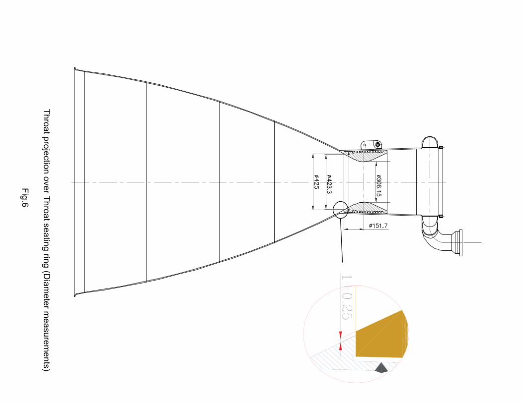
3.3
306.1
5
Thro
at p
roje
ctio
n o
ver T
hro
at s
eatin
g rin
g (D
iam
ete
r measure
ments
)
Fig
.6

����
5
6
Throat seating ring diameter Throat ID measurement at bottom
Diameters overlapped
Throat projection overthroat seating ring
Throat Projection
Fig. 7
��� ������
��
�
�
�
�
��
�
�
��
��
��
��
��
�
�
����
���
��
�
�
��
��
��
��
����
��
�
�
�
�
�
��
��
��
�
�
��
��
��
��
����
��
�
�
�
�
�
��

Inje
cto
r circ
le c
entre
Dia
502m
m
Thro
at c
ircle
centre
Dia
306.1
5 m
m
Exit c
ircle
centre
Dia
1677.9
3 m
m
4m
m
Axis
exte
nded till th
e e
xit
Fig
. 8M
isalig
nm
ent M
easure
ment
AB
C

Injector circle centre Dia 502mm
Throat circle centre Dia 306.15 mm
Exit circle centre Dia 1677.93 mm
Inje
ctor
ref
eren
ce A
xis
exte
nded
till
the
exit
Fig. 8.aThroat and Exit off set Measurement
A
B
C
Throat off set
Exit off set
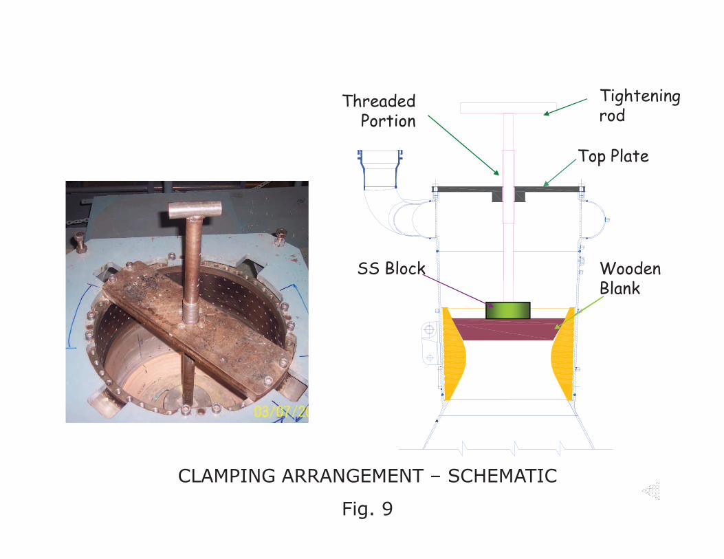
������������
��� ����
����������
�������� ���
�������
����������������� ���������
�����
������

�������������� �����
������������������������������������������������������� ���
�
������������������������� ����� ���� ����
�������

THROAT FIXING OPERATION
EACH LAYER
3. Pouring2. Stirring of 5 min
4. Poking
1. Mixing of cement withDM water
Fig. 11

Fig
.12 G
RIT
BLA
ST
ING
AR
EA
DE
TA
ILS
35050
Inner s
urfa
ce a
rea to
be g
rit bla
ste
d b
efo
re th
roat fix
ing
Com
ple
te D
iverg
ant In
ner s
urfa
ce a
rea
to b
e g
rit bla
ste
d a
nd c
oate
d

Throat
Retainer
Ring SS304L
Th
ru
st
ch
am
ber
Plug welds
Th
roat
1.7
mm
(1.5
-3.5
mm
)
Circumferential TIG welding
Throat
Refractory
cement
Th
ru
st
ch
am
ber
Th
roat
)
Slit weld
������������������� ��������
������

Rubber sheetWooden Fixture
Throat Masking Clamping Arrrangement Shcematic
Fig. 14

������� �������
������� ���������������
���������

������� ��������������
���������