english - 2020
TRANSCRIPT
English - 2020
▪Product Overview
▪ Installation
▪ECU-C configuration
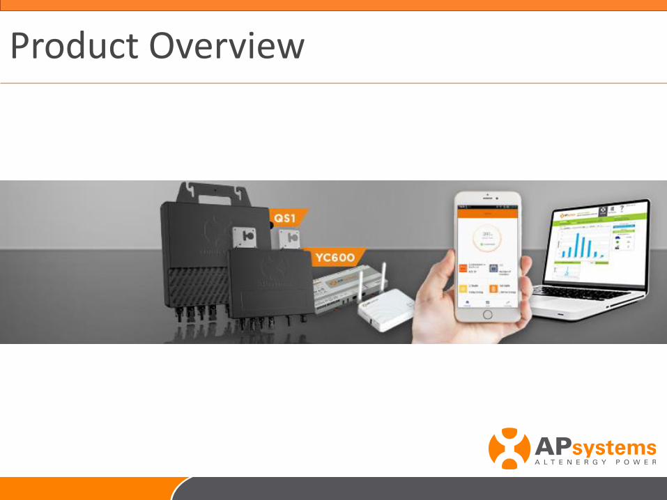
Product Overview
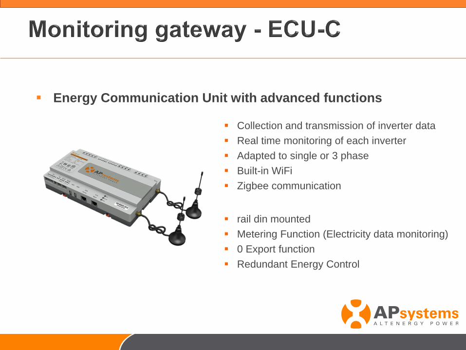
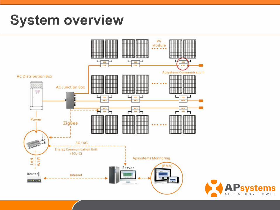
▪ Collection and transmission of inverter data
▪ Real time monitoring of each inverter
▪ Adapted to single or 3 phase
▪ Built-in WiFi
▪ Zigbee communication
▪ rail din mounted
▪ Metering Function (Electricity data monitoring)
▪ 0 Export function
▪ Redundant Energy Control
▪ Energy Communication Unit with advanced functions
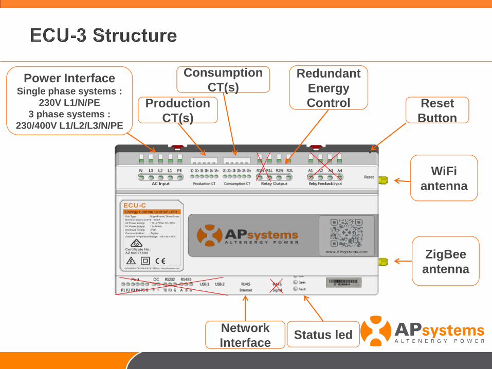
Power InterfaceSingle phase systems :
230V L1/N/PE
3 phase systems :
230/400V L1/L2/L3/N/PE
Network
Interface
Reset
Button
WiFi
antenna
Production
CT(s)
Consumption
CT(s)
ZigBee
antenna
Redundant
Energy
Control
Status led
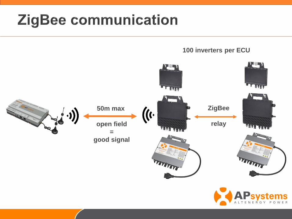
50m max
open field
=
good signal
100 inverters per ECU
ZigBee
relay
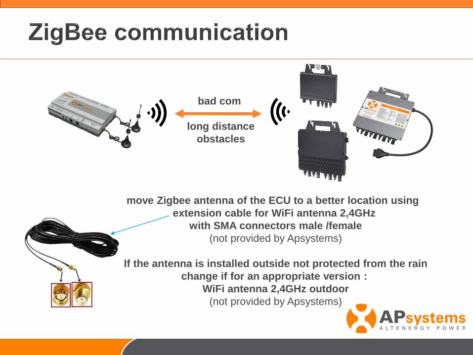
bad com
long distance
obstacles
move Zigbee antenna of the ECU to a better location using
extension cable for WiFi antenna 2,4GHz
with SMA connectors male /female
(not provided by Apsystems)
If the antenna is installed outside not protected from the rain
change if for an appropriate version :
WiFi antenna 2,4GHz outdoor
(not provided by Apsystems)
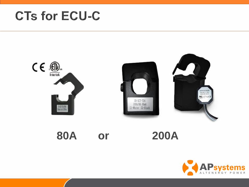
80A or 200A
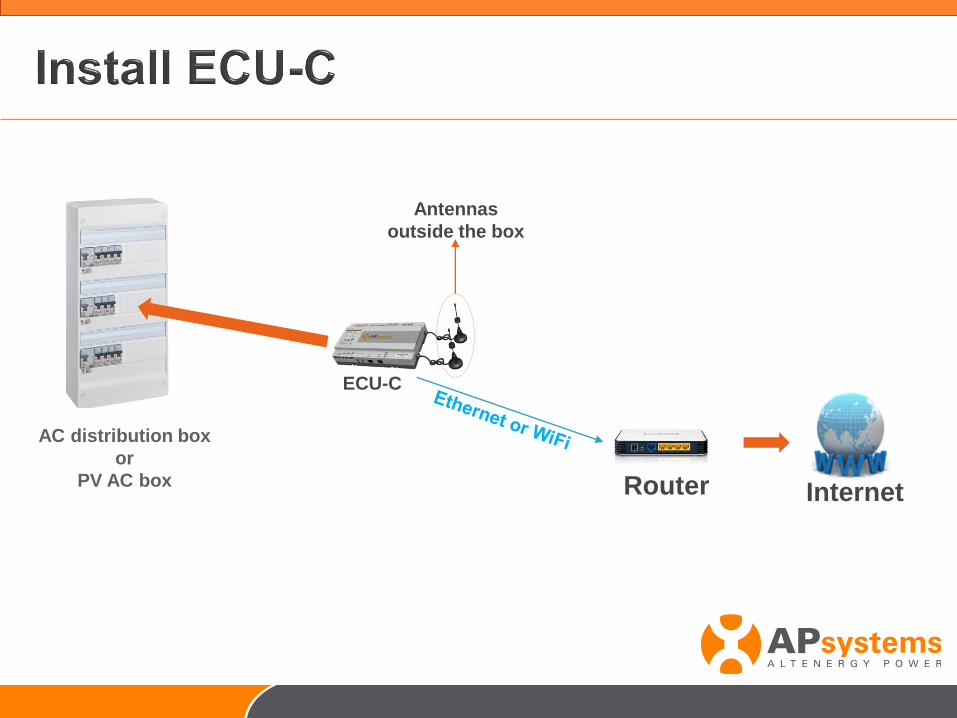
Router Internet
AC distribution box
or
PV AC box
ECU-C
Antennas
outside the box
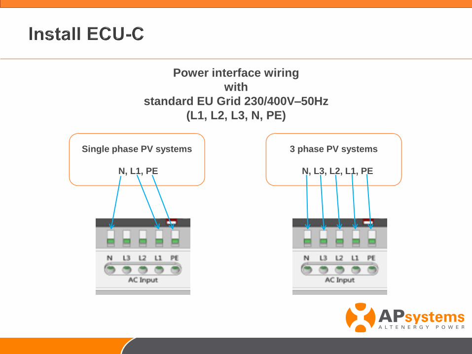
Single phase PV systems
N, L1, PE
Power interface wiring
with
standard EU Grid 230/400V–50Hz
(L1, L2, L3, N, PE)
3 phase PV systems
N, L3, L2, L1, PE
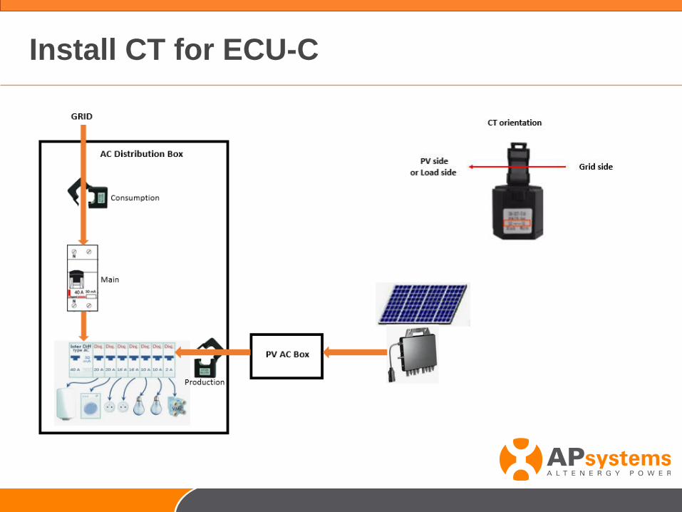
Install CT for ECU-C
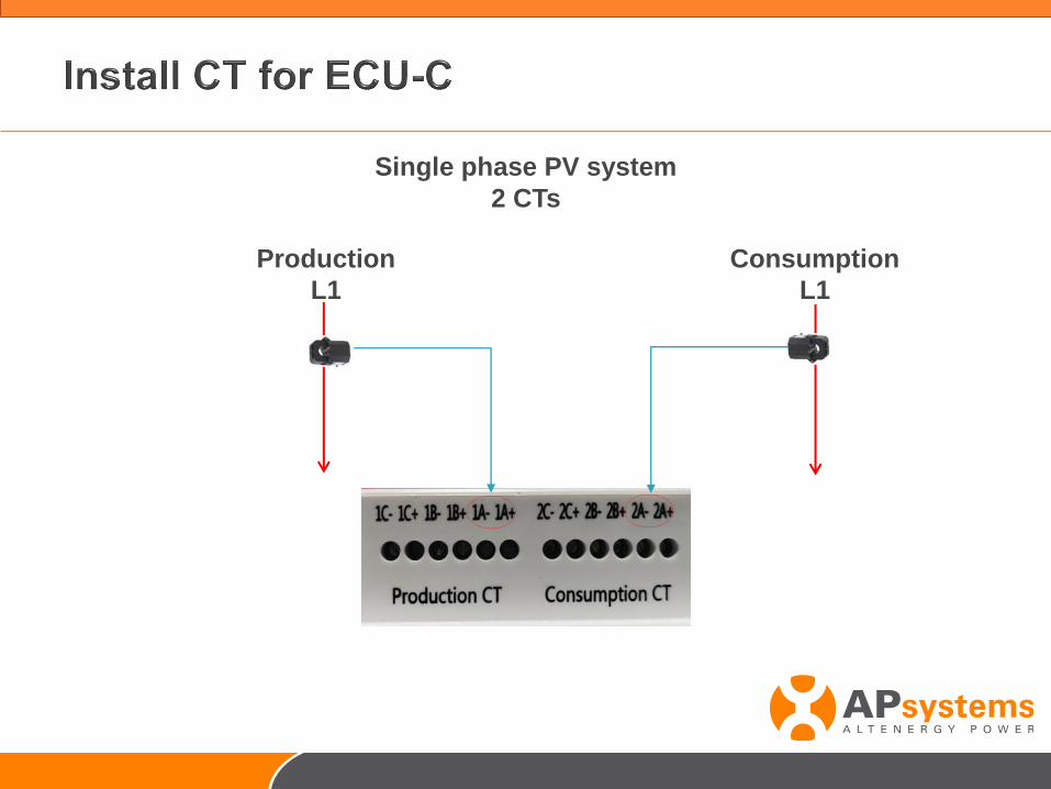
Single phase PV system
2 CTs
Consumption
L1
Production
L1
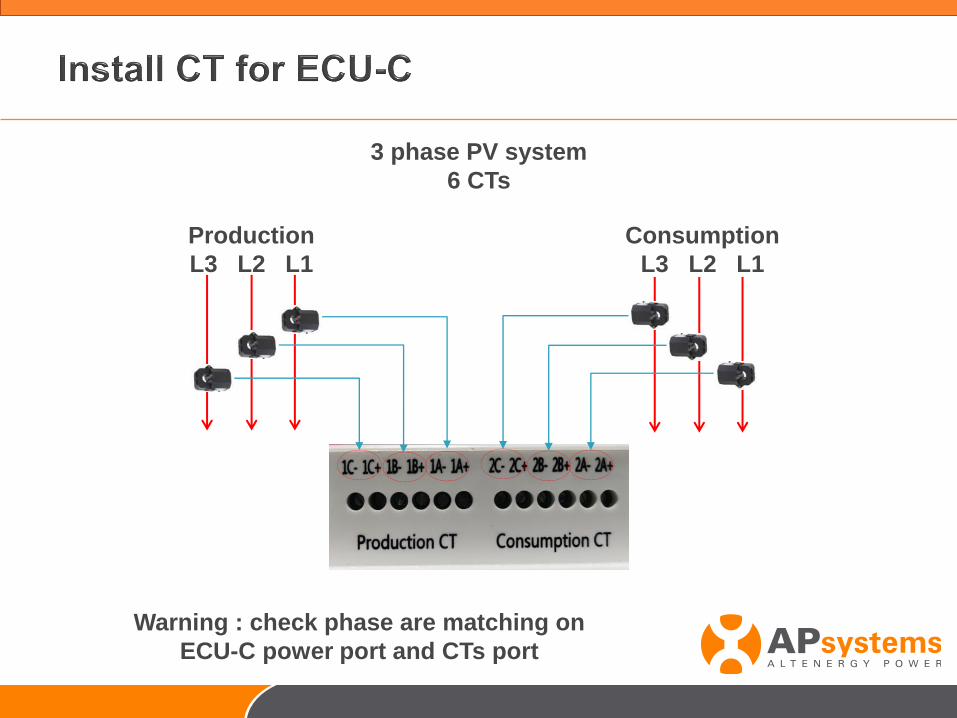
3 phase PV system
6 CTs
Consumption
L3 L2 L1
Production
L3 L2 L1
Warning : check phase are matching on
ECU-C power port and CTs port
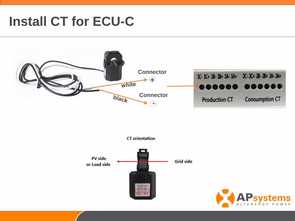
Install CT for ECU-C
Connector
-
Connector
+
Proprietary and confidential. Property of APsystems.17
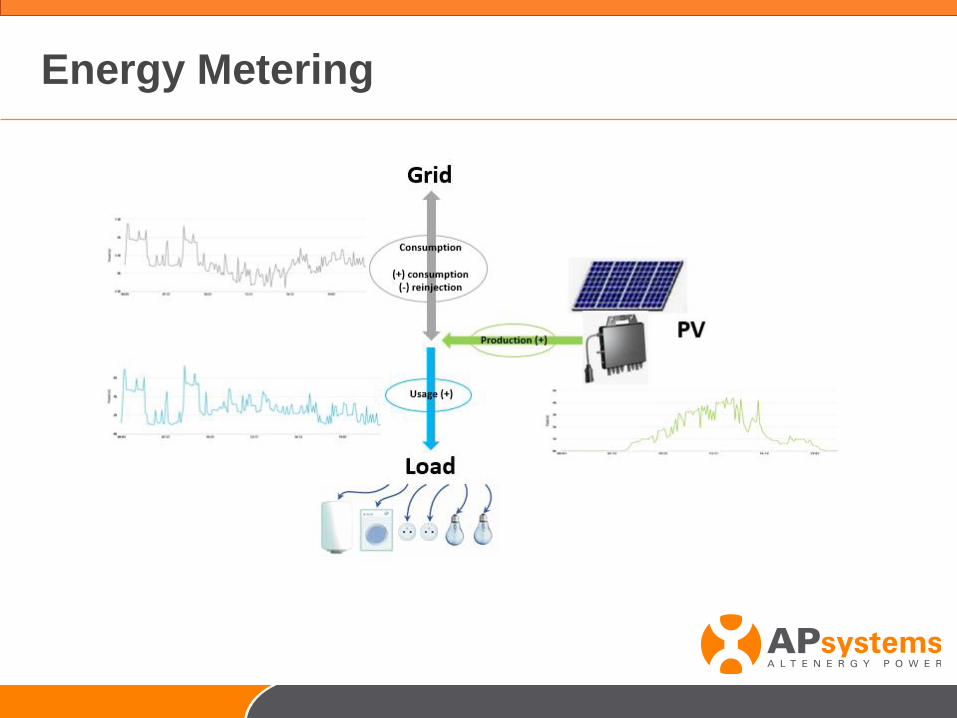
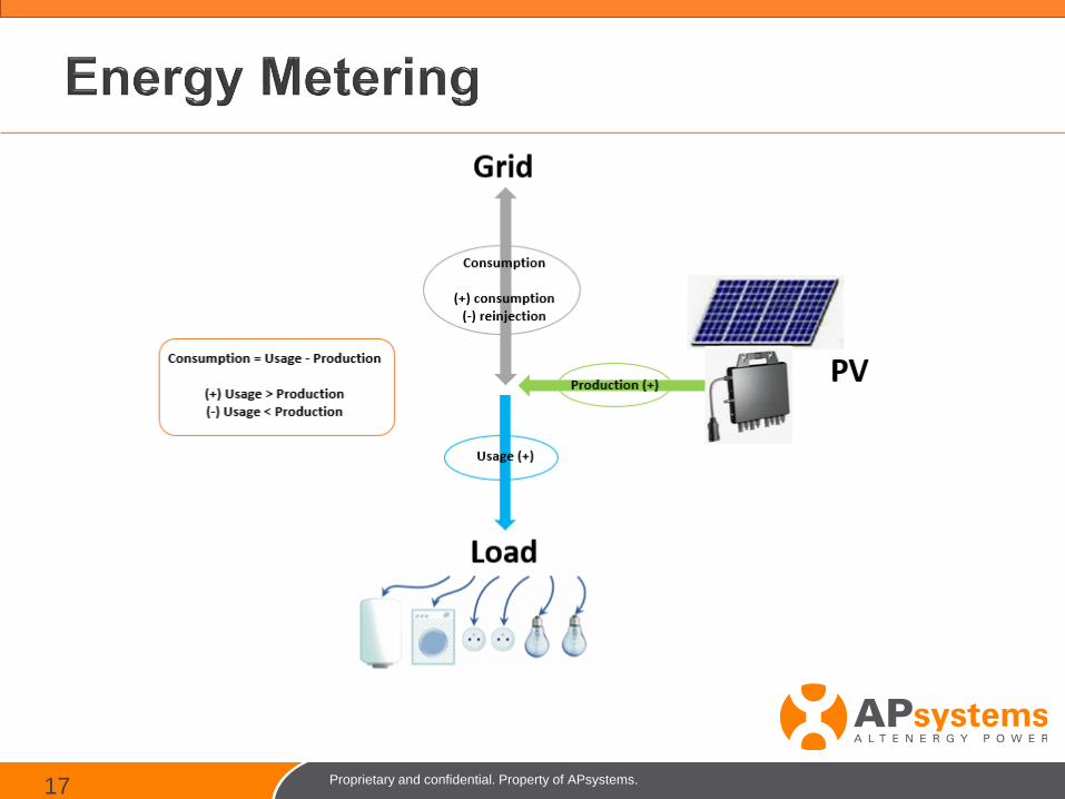
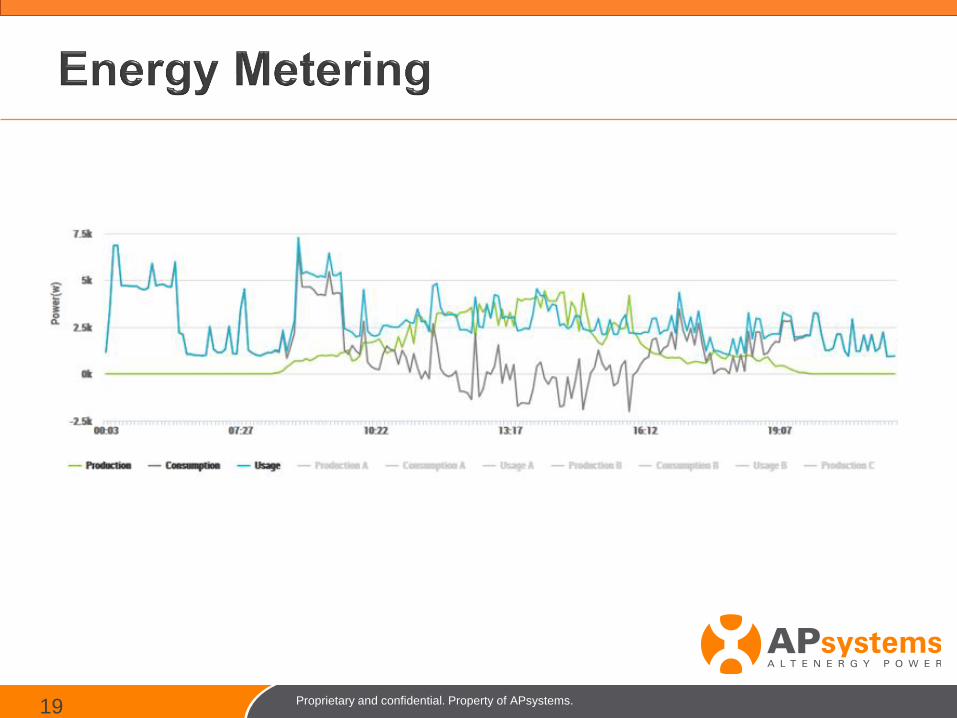
Energy Metering
Proprietary and confidential. Property of APsystems.19
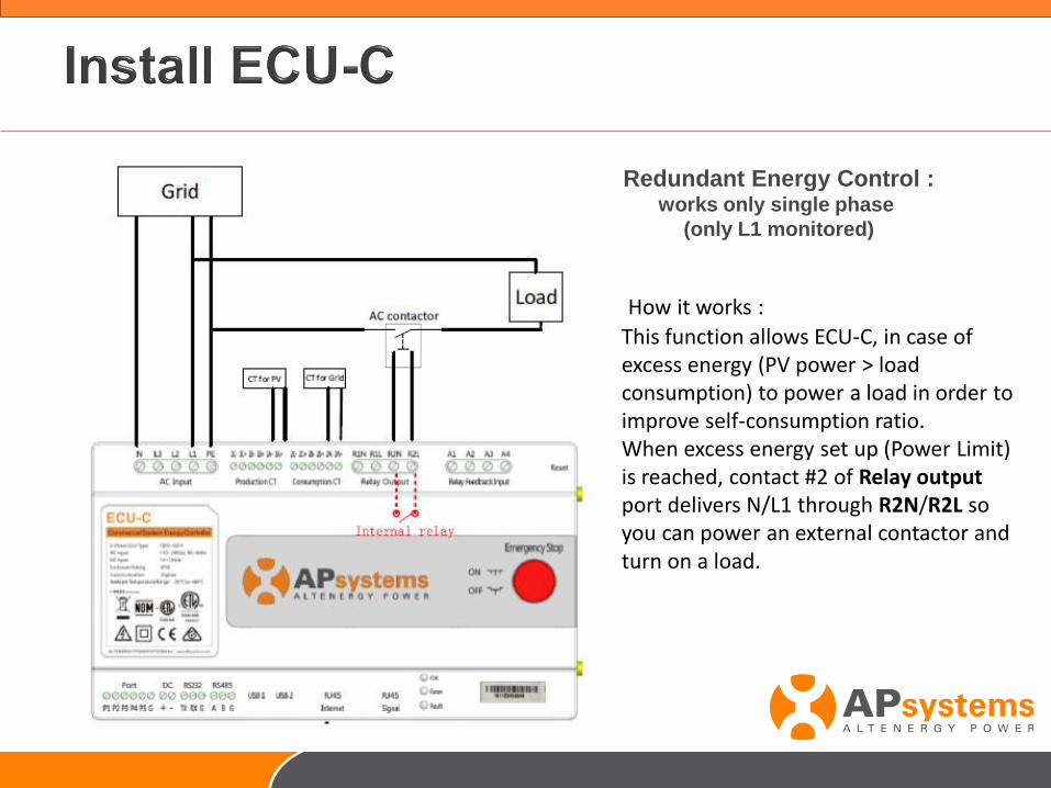
Redundant Energy Control :works only single phase
(only L1 monitored)
How it works :
This function allows ECU-C, in case of excess energy (PV power > load consumption) to power a load in order to improve self-consumption ratio. When excess energy set up (Power Limit) is reached, contact #2 of Relay output port delivers N/L1 through R2N/R2L so you can power an external contactor and turn on a load.
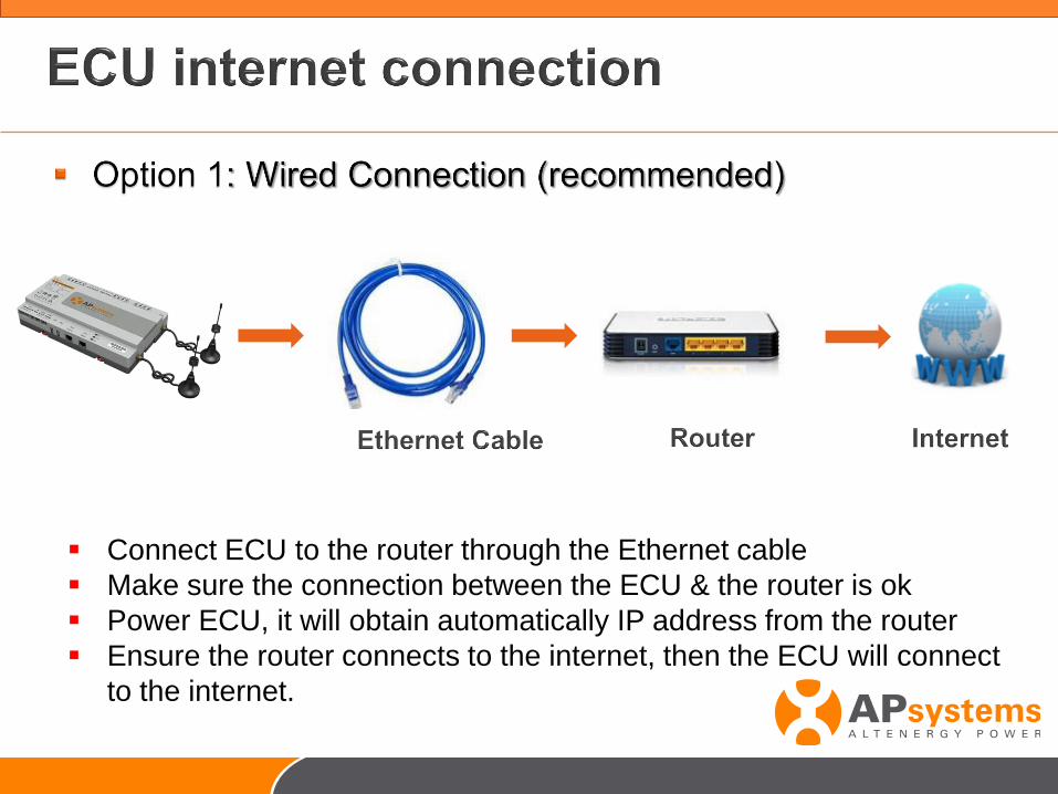
▪ Connect ECU to the router through the Ethernet cable
▪ Make sure the connection between the ECU & the router is ok
▪ Power ECU, it will obtain automatically IP address from the router
▪ Ensure the router connects to the internet, then the ECU will connect
to the internet.
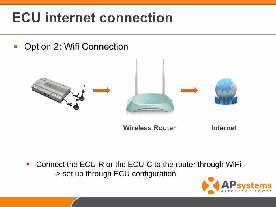
▪ Connect the ECU-R or the ECU-C to the router through WiFi
-> set up through ECU configuration
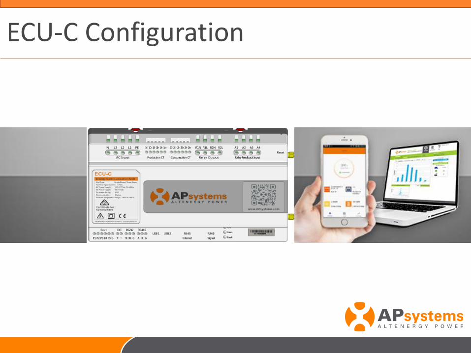
ECU-C Configuration
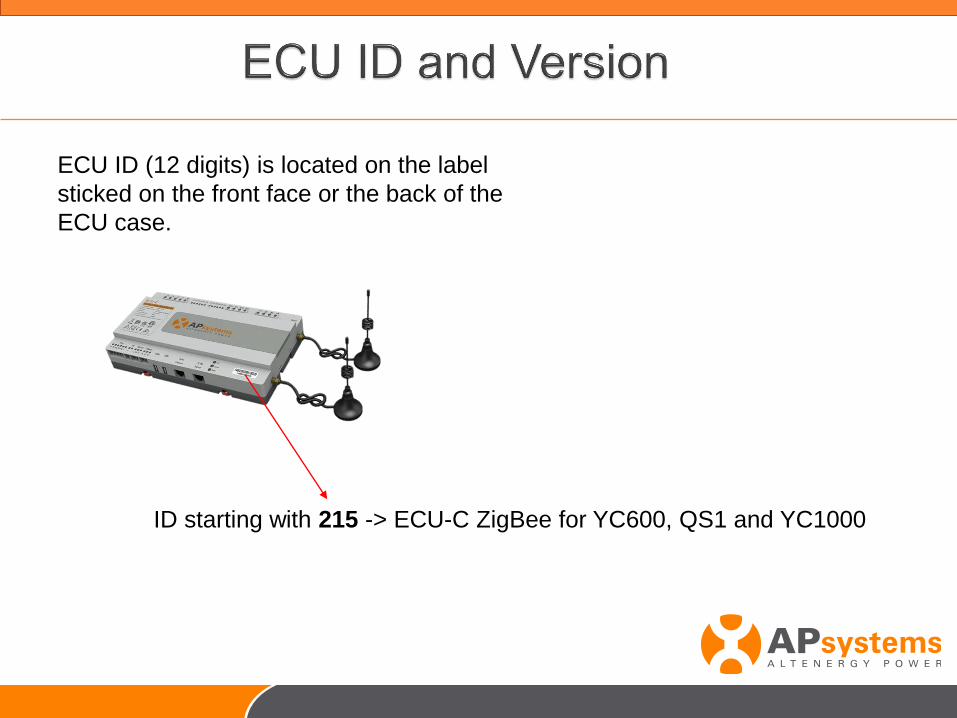
ECU ID (12 digits) is located on the label
sticked on the front face or the back of the
ECU case.
ID starting with 215 -> ECU-C ZigBee for YC600, QS1 and YC1000
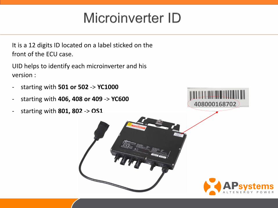
It is a 12 digits ID located on a label sticked on the
front of the ECU case.
UID helps to identify each microinverter and his
version :
- starting with 501 or 502 -> YC1000
- starting with 406, 408 or 409 -> YC600
- starting with 801, 802 -> QS1408000168702
- Connect your smartphone to ECU-C through WiFi
- Log on ECU-C local interface
- Set up ECU-C
- System check up
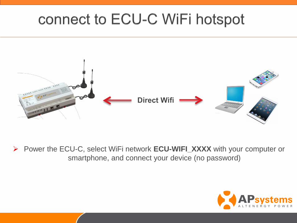
➢ Power the ECU-C, select WiFi network ECU-WIFI_XXXX with your computer or
smartphone, and connect your device (no password)
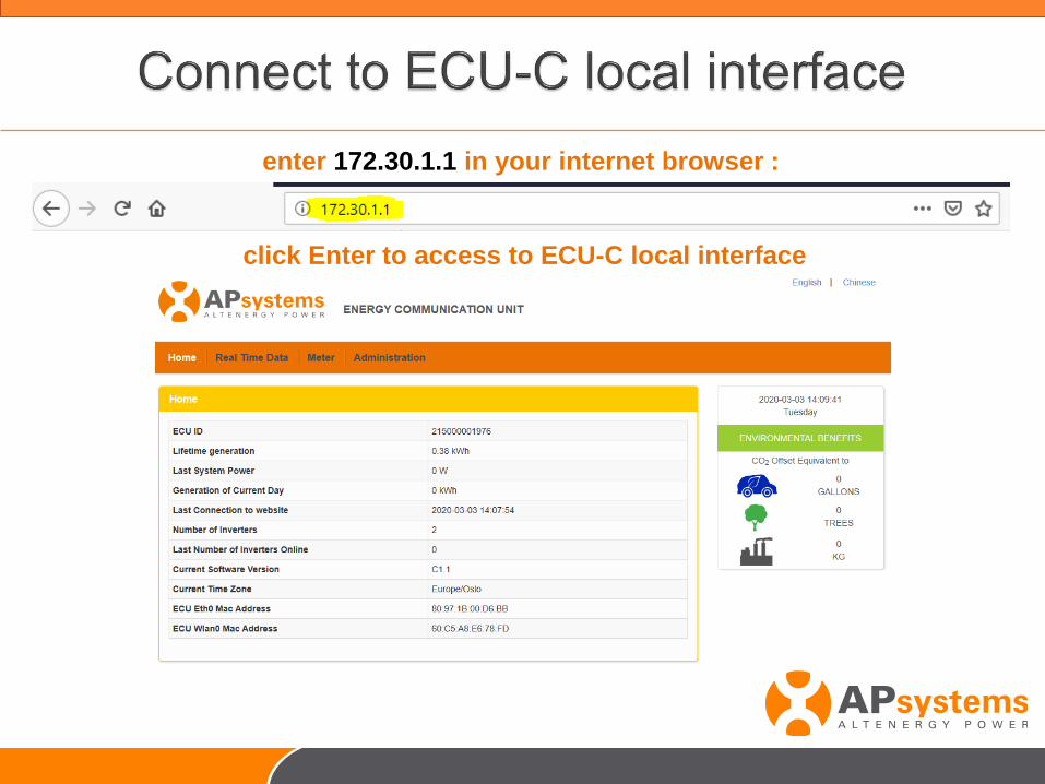
enter 172.30.1.1 in your internet browser :
click Enter to access to ECU-C local interface
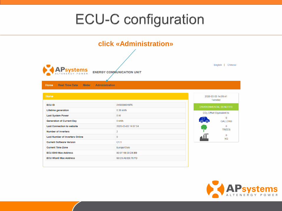
click «Administration»
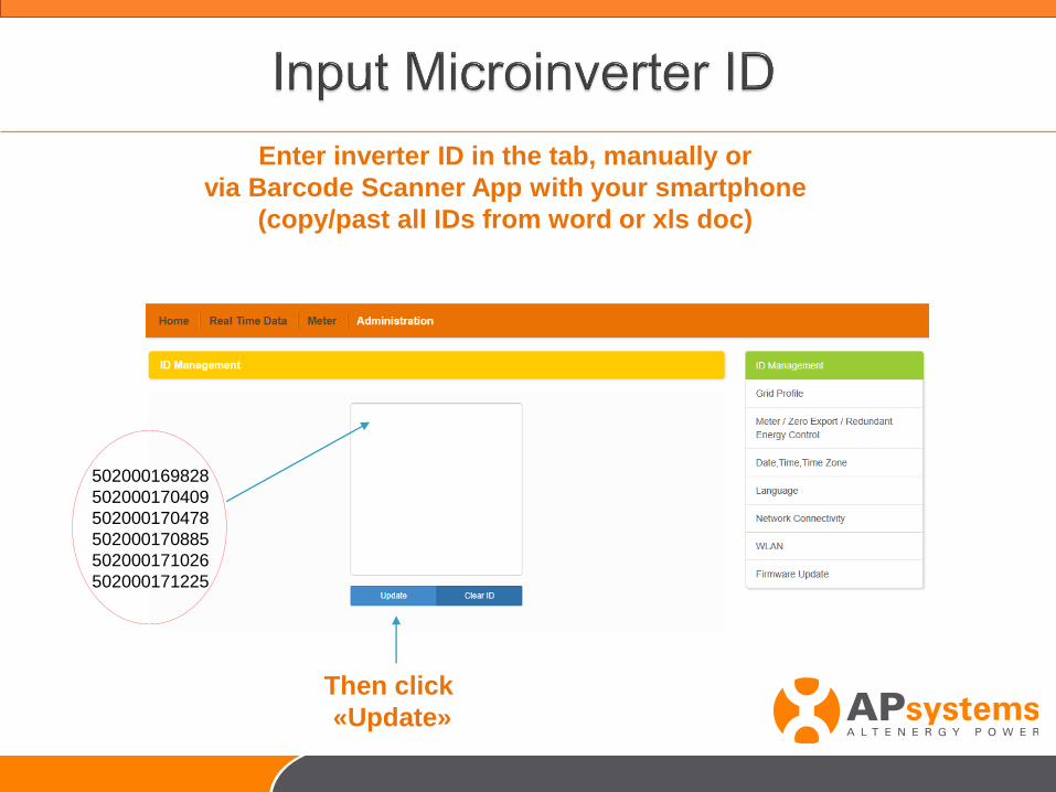
Enter inverter ID in the tab, manually or
via Barcode Scanner App with your smartphone
(copy/past all IDs from word or xls doc)
502000169828
502000170409
502000170478
502000170885
502000171026
502000171225
Then click
«Update»
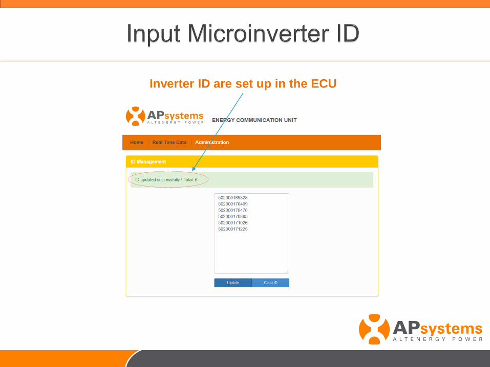
Inverter ID are set up in the ECU
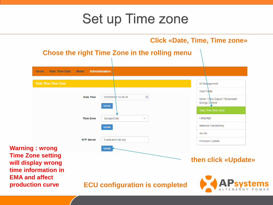
ECU configuration is completed
Click «Date, Time, Time zone»
Chose the right Time Zone in the rolling menu
then click «Update»
Warning : wrong
Time Zone setting
will display wrong
time information in
EMA and affect
production curve
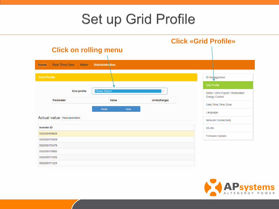
Click «Grid Profile»
Click on rolling menu
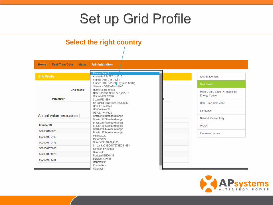
Select the right country
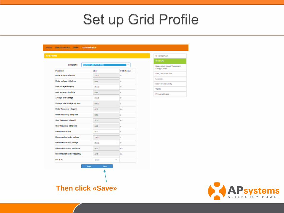
Then click «Save»
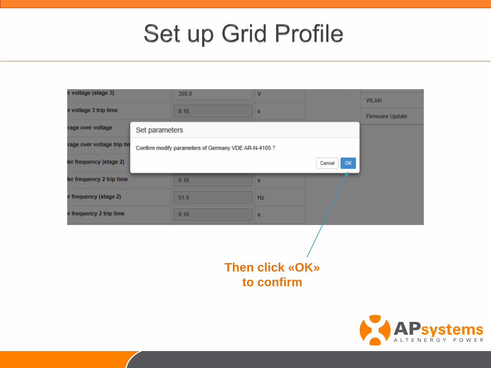
Then click «OK»
to confirm
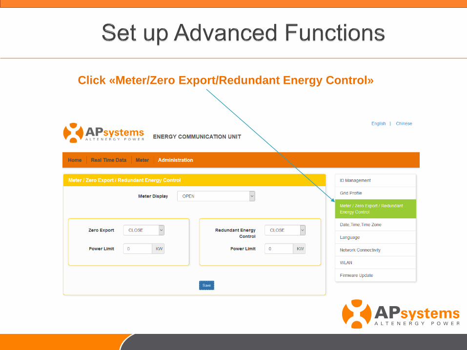
Click «Meter/Zero Export/Redundant Energy Control»
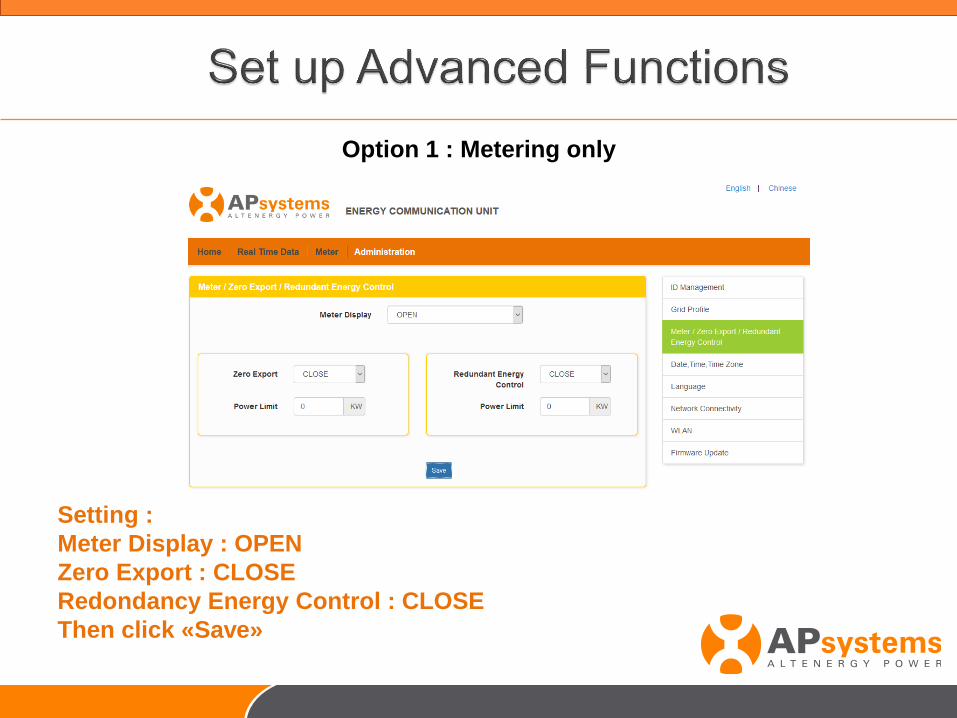
Option 1 : Metering only
Setting :
Meter Display : OPEN
Zero Export : CLOSE
Redondancy Energy Control : CLOSE
Then click «Save»
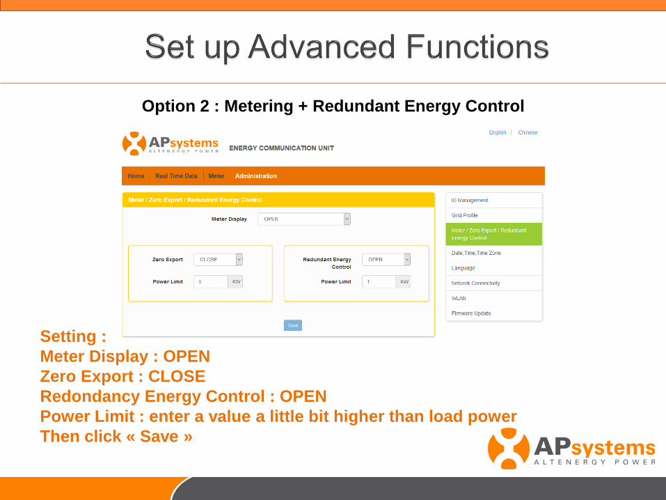
Option 2 : Metering + Redundant Energy Control
Setting :
Meter Display : OPEN
Zero Export : CLOSE
Redondancy Energy Control : OPEN
Power Limit : enter a value a little bit higher than load power
Then click « Save »
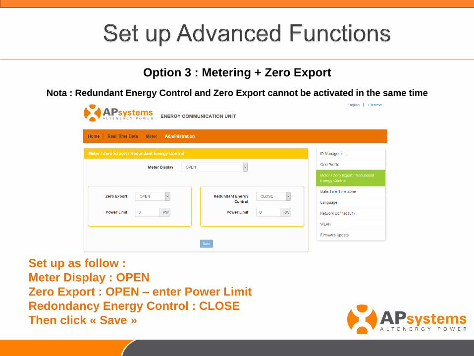
Option 3 : Metering + Zero Export
Nota : Redundant Energy Control and Zero Export cannot be activated in the same time
Set up as follow :
Meter Display : OPEN
Zero Export : OPEN – enter Power Limit
Redondancy Energy Control : CLOSE
Then click « Save »
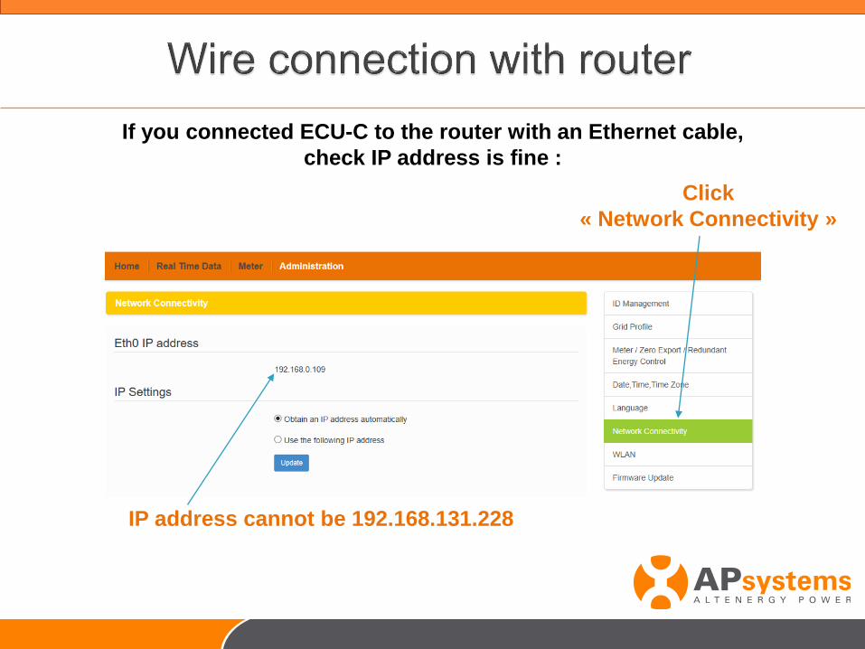
If you connected ECU-C to the router with an Ethernet cable,
check IP address is fine :
Click
« Network Connectivity »
IP address cannot be 192.168.131.228
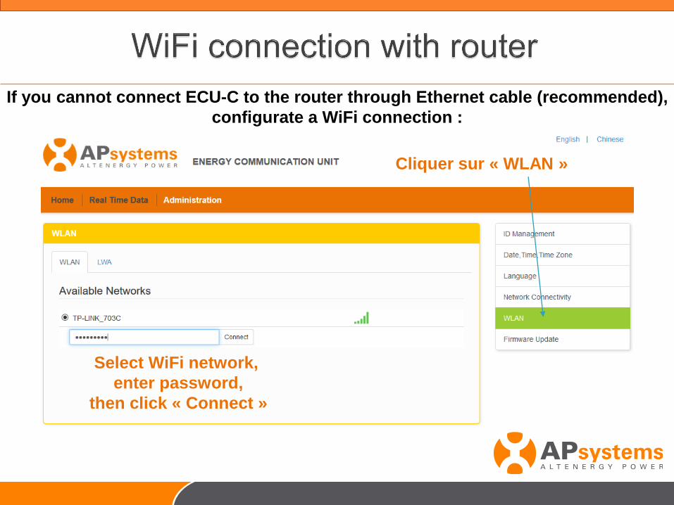
If you cannot connect ECU-C to the router through Ethernet cable (recommended),
configurate a WiFi connection :
Cliquer sur « WLAN »
Select WiFi network,
enter password,
then click « Connect »
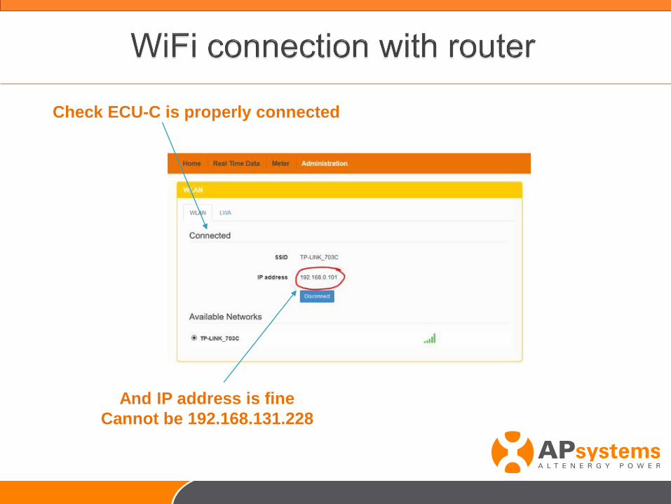
Check ECU-C is properly connected
And IP address is fine
Cannot be 192.168.131.228
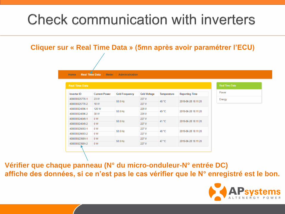
Cliquer sur « Real Time Data » (5mn après avoir paramétrer l’ECU)
Vérifier que chaque panneau (N° du micro-onduleur-N° entrée DC)
affiche des données, si ce n’est pas le cas vérifier que le N° enregistré est le bon.
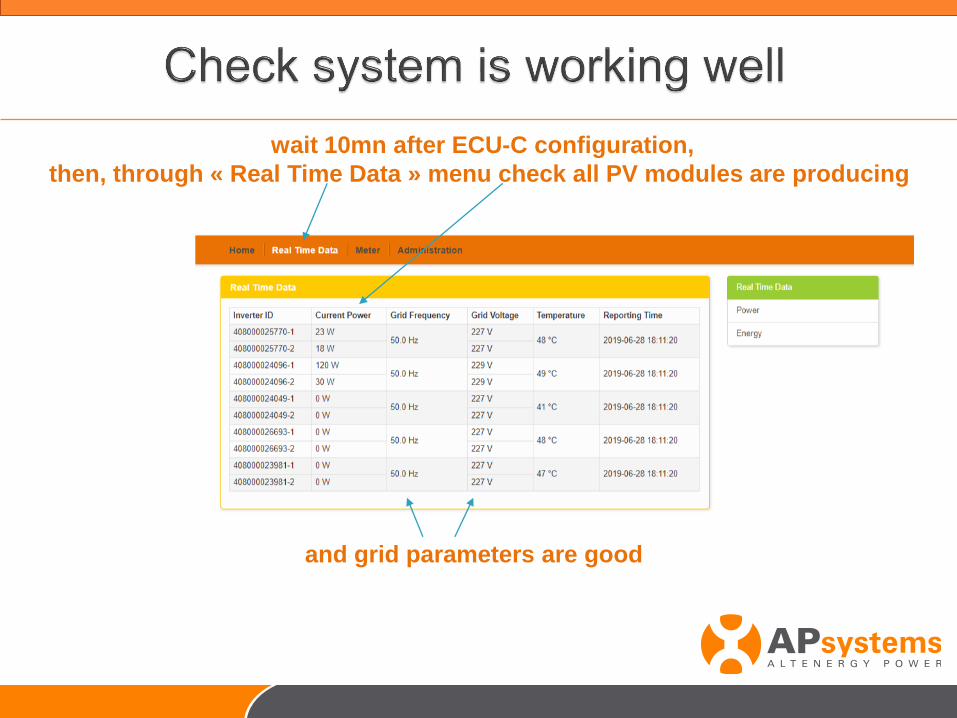
wait 10mn after ECU-C configuration,
then, through « Real Time Data » menu check all PV modules are producing
and grid parameters are good
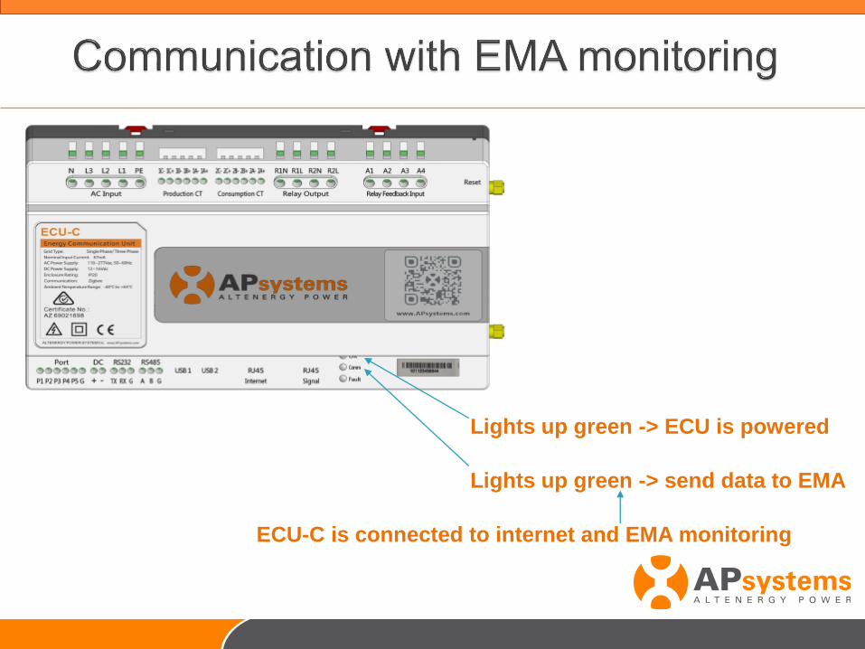
ECU-C is connected to internet and EMA monitoring
Lights up green -> send data to EMA
Lights up green -> ECU is powered