english - delta ohm...following built-in sensors: pressure, temperature, relative humidity, in order...
TRANSCRIPT

Operating manual 3-axis ultrasonic anemometersHD2003 – HD2003.1
www.deltaohm.com
English
Keep for future reference.
Companies / Brands of GHM
HD2003 - 2 - V4.1
INDEX
1. Introduction 1.1. Conventions 1.2. Models
1.2.1. Heaters Option 1.2.2. RS422 Option
1.3. Features 1.4. Operating Modes 1.5. Specifications 1.6. (HD2003 Model) Pressure - Temperature – Relative Humidity Sensors
2. Installation and Maintenance 2.1. Packaging 2.2. Mounting and Positioning 2.3. Alignment 2.4. Electrical Connections
2.4.1. Power Supply and Earthing 2.4.2. RS232 Serial Communication Mode 2.4.3. RS422 Serial Communication Mode 2.4.4. RS485 ModBus RTU and Multidrop Communication Mode 2.4.5. Analog Output Mode 2.4.6. Analog Output Extended Mode AoXnd
2.5. Maintenance
3. Programming 3.1. Introduction 3.2. RS232 and RS422 Serial Communication Mode
3.2.1. Parameter Setup 3.2.2. Measuring mode
3.2.2.1. RS232 Serial Mode Examples 3.2.3. Setup
3.2.3.1. Baud rate 3.2.3.2. Gain 3.2.3.3. Minimum Threshold 3.2.3.4. Average Interval 3.2.3.5. Analog Output Format 3.2.3.6. Output Quantities 3.2.3.7. Unit of Measurement 3.2.3.8. Sonic Transducer Heating 3.2.3.9. RS232, RS422, RS485 and AoXnd Communication Mode 3.2.3.10. Identicode 3.2.3.11. Output Rate and Digital-Analog High Frequency
3.2.4. Logging 3.3. RS485 Multidrop and RS485 ModBus RTU Communication Mode
3.3.1. RS485 Multidrop Parameter Setup 3.3.2. HD2003 Communication Protocol
3.3.2.1. S Command (Setup) 3.3.2.2. M Command (Output Data) 3.3.2.3. H Command (Digital High Frequency enable)
L Command (Digital High Frequency disable) 3.3.3. RS485 ModBus RTU Parameter Setup
3.4. Analog Output Mode 3.4.1. Analog Output Mode Examples
3.5. Analog Output Extended Mode (AoXnd) 3.5.1. Setting ICP DAS I-7024® module 3.5.2. Setting HD2003 3.5.3. Analog Output Extended Mode Examples
4. How to Order 4.1. Order codes

HD2003 - 3 - V4.1
1. INTRODUCTION
Ultrasonic Anemometers allow detecting surface wind speed and direction. These instruments measure the transit time of the ultrasonic pulse between a pair of opposite sonic transducers, in both directions. From the measurement of tA and tR times, you can trace to the wind speed component in the direction of the two transducers, through the formula:
V = D/2 · (1/tA – 1/tR) Where: D = distance between two transducers. tA = forward transit time tR = backward transit time
This formula ensures that the wind speed does not depend on Pressure, Temperature and Humidity. Three couples of transducers allow to make a three-axis vector measurement of wind. 1.1 CONVENTIONS
DEFINITIONS OF THE ANEMOMETRIC QUANTITIES MEASURED BY THE HD2003
The wind direction is established through the calculation of angles: • azimuth The azimuth is the angle that defines the position of the wind flow along the Horizontal Plane, with reference to the direction from which the wind itself is coming. The angle is calculated from 0° to 360° clockwise along the Horizontal Plane. The origin 0° is the direction of Geographical North. The HD2003 built-in integrated compass measures the magnetic azimuth, with reference to Magnetic North. • elevation This is the angle that defines the position of the wind flow along the Vertical Plane. It varies from +/-60° along the Vertical Plane: positive inclinations are those over the Horizontal Plane while the negative ones are those under it.
The wind speed is calculated in terms of intensity of components or resultants: • SoW, SUV and SoS The intensity of wind speed is indicated by SoW, that of its component along the Horizontal Plane U-V is indicated by SUV, while that of sound by SoS. • U-V-W These are the three Cartesian components of wind speed. If we draw a Cartesian plane with U and V along the Horizontal Plane, W will be the Vertical Axis. The “V” direction coincides with Geographical North and, consequently, the “U” will coincide with East and the “W” with the vertical.
The wind gust measurement is determined as follows: • the wind speed averages in a time interval equal to 3 seconds are calculated continuously; • the maximum value of the averages calculated in the previous point is detected over a time
interval equal to the Average Interval set in the instrument; the maximum value detected is the measure of wind gust.
Note: the wind gust measure is not averaged over the Averaging Interval, but the Averaging Interval is only taken as a reference for the duration of the interval in which to detect the maximum value. The wind gust measurement only reports the wind intensity, not the direction.
OTHER CONVENTIONS • F.S. and Zero F.S. identifies the Full Scale of a quantity, while Zero identifies the Scale Minimum Value. • Factory Default The Factory Default corresponds to the value of a factory set parameter, when first programming an instrument which comes out of the production department. • Internal Refresh It represents the automatic frequency by which all the calculations are refreshed according to the set average intervals.

HD2003 - 4 - V4.1
• Symbols The keys of an IBM compatible PC keyboard are identified with a white text on a black background, for example:
[Esc] = Esc key, [Enter] = Enter key, [A] = A key
One ASCII generic character or several ASCII generic characters can be identified with the symbol: <name>, where name is any expression that gives the title to that character. Example of peculiar characters: <CR> = Carriage Return <LF> = Line Feed • Output Data It is the digital string of all formatted measuring data available for RS232, RS422, AoXnd and RS485 Serial communication interfaces. 1.2 MODELS The code HD2003 mentioned in this manual refers to both models:
HD2003 HD2003.1
They represent the same kind of Anemometer, except for the fact that the HD2003 has the following built-in sensors: Pressure, Temperature, Relative Humidity, in order to measure these additional output quantities. When necessary, the difference between the two models is unequivocally underlined. 1.2.1 HEATERS OPTION The HD2003 is guaranteed to function in temperatures as low as –20°C if ice or snow is absent, without any heating circuits for sonic transducers. Temperature conditions below –20°C, or temperatures around 0°C when snowing or ice possibly forms on the transducers, prevent the HD2003 from functioning correctly, making the use of the heaters option essential. The heating circuit intervenes at temperatures below +5°C, with a minimum additional power of 4 W (with temperature no lower than –10°C), preventing the formation of ice, and ensuring that the HD2003 functions correctly even during sleet or snow. The defrosting time depends on the quantity of snow that has deposited on the measurement volume where the ultrasonic sensors are housed. The models equipped with the heaters option are named with the additional letter R:
HD2003R HD2003.1R
1.2.2 RS422 OPTION
The RS422 serial communication mode works with an internal circuit, which must be requested as an option when ordering and which provides a 4-wire full duplex communication.

HD2003 - 5 - V4.1
1.3 FEATURES The HD2003 main features are: ♦ Determination of anemometric quantities with different units of measurement: wind speed
and direction, U-V-W Cartesian components, wind gust, sonic speed and temperature. ♦ (HD2003 Model) Additional quantities measured: pressure, temperature, relative humidity. ♦ 5 analog outputs in current or voltage, with different ranges. ♦ Up to 12 extended analog outputs in current and voltage, at different measuring ranges. ♦ 5 digital communication interfaces: Serial RS232, RS422, RS485 Modbus, RS485 proprietary
and AoXnd. ♦ Digital strings of output data at a configurable emission frequency. ♦ Average intervals for all output quantities, configurable at 1÷60 sec or at 1÷60 min. ♦ Processing and validity Algorithms for raw measurement signals to provide the
measurement of the anemometric quantity with ±1% precision. ♦ Operating mode at High Digital Frequency with serial data output at 50 Hz, or High Analog
Frequency with analog data output from 5Hz to 20Hz. ♦ Self-diagnosis with checking and error reporting. ♦ Reliability and precision for the whole measurement field, without any need for further
calibrations. ♦ Flexible and easy-to-use demonstration software which can be adapted to the customer’s
requirements through a computer interface. ♦ Setup user interface and software upgrade via RS232, RS422 or RS485. ♦ Compass with magnetoresistive sensor for automatic alignment to the Magnetic North. ♦ No moving parts, with reduced maintenance and servicing costs. ♦ Robust construction, suitable to operate continuously in severe climatic conditions. ♦ Low power consumption.
♦ (On request) Heaters Option: Sonic transducers integrated heating device, to prevent ice and snow formation, ensuring a correct functioning even when sleeting or snowing.
♦ (On request) RS422 Option: 4-wire full duplex RS422 communication integrated circuit.
HD2003 - 6 - V4.1
1.4 OPERATING MODES The HD2003 has five operating modes: ♦ RS232 and RS422 Serial Communication Mode (Chap. 3.2) A connection over a RS232 or RS422 Serial line is established between a Host Computer and only one HD2003 Anemometer. The Host Computer (Slave) is continuously receiving on its RS232 serial port, Output Data digital strings, which are automatically supplied by HD2003 (Master), with its own frequency (configurable at a cadence from 1 to 3600s). In this mode the Setup user interface can be managed from the computer. ♦ RS485 ModBus – RS485 Multidrop Communication Mode (Chap. 3.3) A network with ModBus RTU protocol over the RS485 line can be established, with a Master (typically the PC or PLC) and one or more HD2003 anemometers together with other sensors, all operating as Slave unit. Or a RS485 Multidrop network can be established between a Host Computer and several HD2003 or HD52.3D anemometers (up to 32). The Host Computer (Master) sends a command to the univocal address of a HD2003 (Slave). Only the Anemometer which is identified by that address answers on request, giving the Output Data. In this mode the command to activate the Setup user interface is available. ♦ Digital High Frequency Mode (Chap. 3.2.3.11 and Chap. 3.3.2.3) When in RS232 or RS422 serial communication mode, the Digital High Frequency functioning can be set up, by obtaining Output Data of the quantities in RS232 or RS422 at a fixed frequency of 50 Hz (baud rate=115200 and 4 measurement quantities). When in RS485 Multidrop communication mode, a command for activating the Digital High frequency can be sent. Then, any command for requiring a measurement can be sent to the HD2003 up to a maximum frequency of 50 Hz (baud rate=115200 and 4 measurement quantities). ♦ Analog Output Mode (Chap. 3.4) All measurement quantities can be configured to be converted into 5 analog outputs in current or voltage, available in different measurement ranges, with a refresh of 1Hz. This mode is always active, combined with the RS232 Serial, RS422, AoXnd and RS485 Multidrop modes. When on Digital or Analog High Frequency mode, the 5 analog outputs are still available with a refresh of 1Hz. ♦ Analog Output Extended Mode (AoXnd) - Analog High Frequency ( Chap. 3.5 ) A single HD2003 Anemometer (Master) sends spontaneously digital strings of command over his RS485 serial line directly connected to a remote module (Slave) ICP DAS I-7024 ® (provided on Request). There are 4 extended analog outputs, voltage or current, to the output terminals of the module, related to the measured quantities requested. Up to 3 ICP DAS I-7024® modules can be connected, for a maximum total of 12 extended analog output. In normal operation, cadences are settable from 1 to 3600s of update of the analog outputs, that is to say a maximum frequency of 1Hz. Under this mode, it is possible to get analog outputs at a considerable distance from the place of installation of the HD2003, up to 1200m, even in routes subject to high electromagnetic interference. The analog signals to the output terminals of the module, placed in proximity of the acquisition device (such as the data logger DeltaOHM HD32MT.1), are electrically insulated and are not subject to disturbances and interference in the electrical path forming, as it happens in the analog signals that come directly from anemometer and have a long way before reaching acquisition device. Under this mode of AoXnd communication, the High Frequency Analog operation can be set, by getting the analog output of the measuring quantities needed, at a frequency of 5Hz to 20Hz, depending on the baud rate of the digital strings of command over the RS485 line. The Serial RS232, RS422, RS485 ModBus RTU, RS485 Multi-drop and AoXnd Communication modes are alternative: only one of them can be active. Their activation is obtained via software (see Chap. 3.2.3.9), subsequently switching the HD2003 off and on. It is always possible to return to RS232 Serial mode by providing a suitable command when switching the HD2003 on.
HD2003 - 7 - V4.1
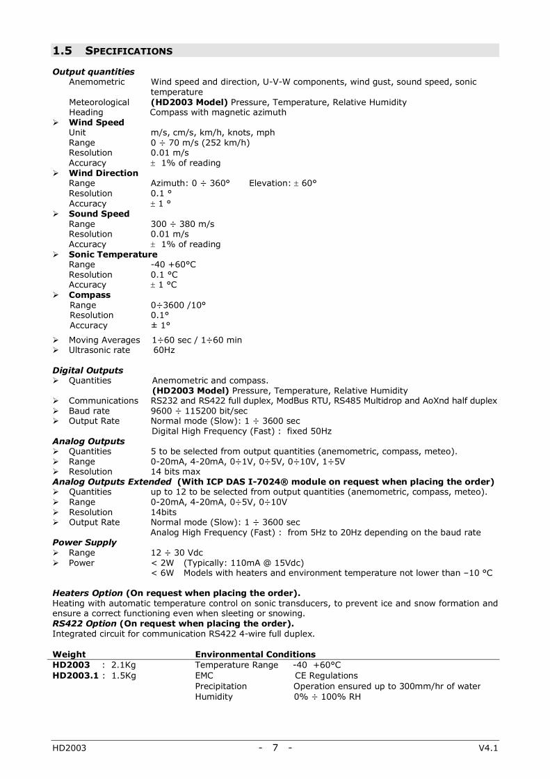
1.5 SPECIFICATIONS Output quantities
Anemometric Wind speed and direction, U-V-W components, wind gust, sound speed, sonic temperature
Meteorological (HD2003 Model) Pressure, Temperature, Relative Humidity Heading Compass with magnetic azimuth
Wind Speed Unit m/s, cm/s, km/h, knots, mph Range 0 ÷ 70 m/s (252 km/h) Resolution 0.01 m/s Accuracy ± 1% of reading
Wind Direction Range Azimuth: 0 ÷ 360° Elevation: ± 60° Resolution 0.1 ° Accuracy ± 1 °
Sound Speed Range 300 ÷ 380 m/s Resolution 0.01 m/s Accuracy ± 1% of reading
Sonic Temperature Range -40 +60°C Resolution 0.1 °C Accuracy ± 1 °C
Compass Range 0÷3600 /10° Resolution 0.1° Accuracy ± 1°
Moving Averages 1÷60 sec / 1÷60 min Ultrasonic rate 60Hz
Digital Outputs
Quantities Anemometric and compass. (HD2003 Model) Pressure, Temperature, Relative Humidity
Communications RS232 and RS422 full duplex, ModBus RTU, RS485 Multidrop and AoXnd half duplex Baud rate 9600 ÷ 115200 bit/sec Output Rate Normal mode (Slow): 1 ÷ 3600 sec
Digital High Frequency (Fast) : fixed 50Hz Analog Outputs
Quantities 5 to be selected from output quantities (anemometric, compass, meteo). Range 0-20mA, 4-20mA, 0÷1V, 0÷5V, 0÷10V, 1÷5V Resolution 14 bits max
Analog Outputs Extended (With ICP DAS I-7024® module on request when placing the order) Quantities up to 12 to be selected from output quantities (anemometric, compass, meteo). Range 0-20mA, 4-20mA, 0÷5V, 0÷10V Resolution 14bits Output Rate Normal mode (Slow): 1 ÷ 3600 sec
Analog High Frequency (Fast) : from 5Hz to 20Hz depending on the baud rate Power Supply
Range 12 ÷ 30 Vdc Power < 2W (Typically: 110mA @ 15Vdc)
< 6W Models with heaters and environment temperature not lower than –10 °C Heaters Option (On request when placing the order). Heating with automatic temperature control on sonic transducers, to prevent ice and snow formation and ensure a correct functioning even when sleeting or snowing. RS422 Option (On request when placing the order). Integrated circuit for communication RS422 4-wire full duplex. Weight Environmental Conditions HD2003 : 2.1Kg Temperature Range -40 +60°C HD2003.1 : 1.5Kg EMC CE Regulations Precipitation Operation ensured up to 300mm/hr of water Humidity 0% ÷ 100% RH

HD2003 - 8 - V4.1
1.6 (HD2003 MODEL) PRESSURE - TEMPERATURE – RELATIVE HUMIDITY SENSORS Pressure. Piezoresistive Sensor Analog Output: 0-20mA, 4-20mA, 0÷1V, 0÷5V, 0÷10V, 1÷5V Analog Output Extended (AoXnd): 0-20mA, 4-20mA, 0÷5V, 0÷10V Range: 600 ÷ 1100 mbar Resolution: 0.1 mbar Accuracy: ± 0.4 mbar @ 20 °C Temperature Effects: ± 0.8mbar between –40°C and +60°C Long-term stability: 1mbar in 6 months @ 20 °C Temperature. Sensor: Pt100 Analog Output: 0-20 mA, 4-20 mA, 0÷1V, 0÷5V, 0÷10V, 1÷5V Analog Output Extended (AoXnd): 0-20mA, 4-20mA, 0÷5V, 0÷10V Range : –40 + 60 °C Resolution: 0.1 °C Accuracy: ± 0.2 °C, ± 0.15% of reading Relative Humidity. Capacity sensor: H6100 Analog Output (0 %÷100 % RH): 0-20mA, 4-20mA, 0÷1V, 0÷5V, 0÷10V, 1÷5V Analog Output Extended (AoXnd): 0-20mA, 4-20mA, 0÷5V, 0÷10V Range: 5÷98% RH Resolution: 0.1 % Accuracy: ± 2.5% RH @ 23°C
HD2003 - 9 - V4.1
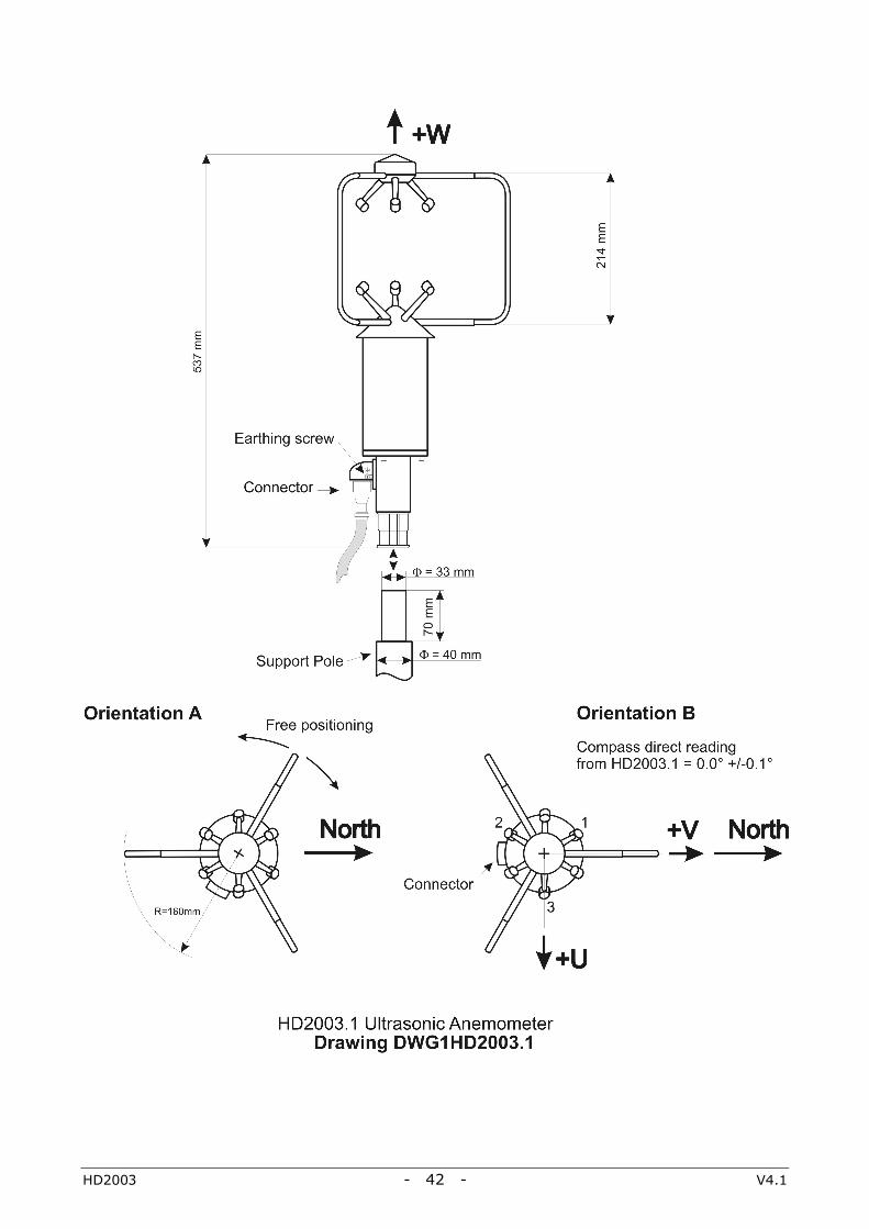
2. INSTALLATION AND MAINTENANCE 2.1 PACKAGING In order to avoid damage due to transport, the HD2003 Anemometer is supplied fixed in a special container. Carefully remove the Anemometer from its container and save this one, for any future packaging and transport. The warranty does not cover the instrument if, in further shipments, containers other than the one supplied are used, or if the HD2003 is not fixed inside it. 2.2 MOUNTING AND POSITIONING The instrument will be vertically mounted and positioned on “open terrain”, far from turbulences due to near trees or buildings. In the presence of buildings, trees or any other obstruction, the HD2003 should be positioned at a height of 10 meters above the ground; the distance between the instrument and any obstruction should be at least 10 times the relevant height. 2.3 ALIGNMENT (SEE DRAWING DWG1HD2003 PAGE 41) ORIENTATION A If the HD2003 is rotated on its vertical axis, it can be fixed in any other angular position. The HD2003 built-in magnetoresistive sensor allows to automatically refer angular measurements to Magnetic North, independently of its position. ORIENTATION B The HD2003 is connected to a computer in RS232 Serial, RS422 or RS485 Multidrop communication mode (Chap. 3.2 and Chap. 3.3). Then the HD2003 is rotated on its vertical axis until the measurement of the compass shows 0.0° +/- 0.1° on the serial communication program of the computer. This ‘Orientation B’ ensures greater precision in angular measurements and U-V-W Cartesian components of wind speed correspond to cardinal points: V direction= North U direction = East W direction = Instrument Vertical Axis. In order to refer angular measurements to Geographical North, you should consider the Magnetic Declination error, which is to be algebraically summed to Magnetic North. Once the alignment is finished, tighten the clamp which fixes HD2003 to the mounting mast. With strong magnetic fields, (for example radio or telephone antennas are in the same installation), the automatic calculation of the azimuth angle, may be independent from the compass meaurement. In order to do it, make an RS232 serial connection (Chapter 2.4.2), and if you press # on the keyboard of the Host computer, when turning the HD2003 on, (auto ranging takes a few seconds), you set it up to work with manual North orientation. To align the instrument, rotate the HD2003 on its vertical axis, so the Geographical North corresponds to the north side of HD2003, which is identified by the direction of the metal support opposite the connector (see Orientation B, Drawing DWG1HD2003 page 41). 2.4 ELECTRICAL CONNECTIONS Electrical connections to the HD2003 are made with its 26 pole connector. Each pin of the connector, is marked with an identity label and a mnemonic symbol. See HD2003 Connector on page 38 for references to connector labels and symbols. (On request) Multipolar cable: the HD2003 may be supplied with a cable and plug. Various lengths of the cable are available. (On request) USB cable RS2003: The HD2003 can be supplied with a cable for connection to the USB port of a PC and a power supply.
HD2003 - 10 - V4.1
2.4.1 POWER SUPPLY AND EARTHING
♦ Power supply: 12÷30 Vdc 110mA @ 15Vdc: without Heaters Option 400mA @ 15Vdc and –10°C: with Heaters Option (heating circuit activated) Power Supply 12÷30 Vdc
HD2003 Connector / Symbol
pole G / PWR+ pole − H / PWR-
Note for the model with Heaters Option: When the HD2003 has remained off in temperatures below 0°C, being switched on later will give initial absorption peaks when the heating circuit turns on. These peaks should be planned when dimensioning the power supply circuit used (absorption: from 5A to 1A first 5sec @ 15Vdc and –20°C). For greater effectiveness of the heating circuit, it is advisable to use a Power Supply of 30Vdc, by connecting two pairs of wires, one towards the poles G and K (PWR +) and the other one towards the poles and J and H (PWR-) of the connector of the HD2003. (In RS422 the poles K and J are not available).
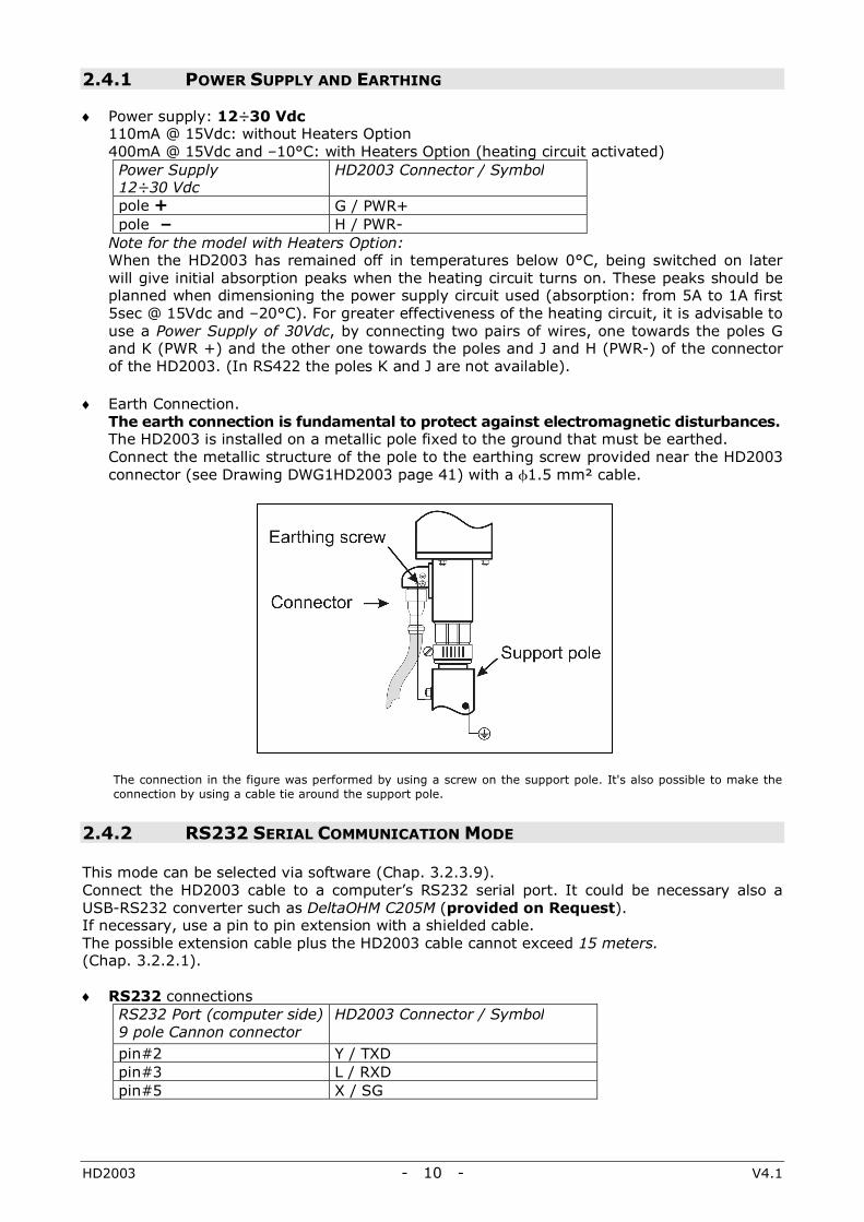
♦ Earth Connection. The earth connection is fundamental to protect against electromagnetic disturbances. The HD2003 is installed on a metallic pole fixed to the ground that must be earthed. Connect the metallic structure of the pole to the earthing screw provided near the HD2003 connector (see Drawing DWG1HD2003 page 41) with a φ1.5 mm² cable.
The connection in the figure was performed by using a screw on the support pole. It's also possible to make the connection by using a cable tie around the support pole.
2.4.2 RS232 SERIAL COMMUNICATION MODE This mode can be selected via software (Chap. 3.2.3.9). Connect the HD2003 cable to a computer’s RS232 serial port. It could be necessary also a USB-RS232 converter such as DeltaOHM C205M (provided on Request). If necessary, use a pin to pin extension with a shielded cable. The possible extension cable plus the HD2003 cable cannot exceed 15 meters. (Chap. 3.2.2.1). ♦ RS232 connections
RS232 Port (computer side) 9 pole Cannon connector
HD2003 Connector / Symbol
pin#2 Y / TXD pin#3 L / RXD pin#5 X / SG
HD2003 - 11 - V4.1
2.4.3 RS422 SERIAL COMMUNICATION MODE
This mode can be selected via software (Chap. 3.2.3.9). Connect the cable of the HD2003 to the RS232/RS422 converter connected to the computer. The cable length can be at maximum 1,200m. ♦ RS422 connections
RS422 Port (computer side)
HD2003 Connector / Symbol
Polo Tx B J / Tx + Polo Tx A K / Tx - Polo Rx B F / Rx + Polo Rx A W / Rx -
2.4.4 RS485 MODBUS RTU AND MULTIDROP COMMUNICATION MODE This mode can be selected via software (Chap. 3.2.3.9). Make a parallel connection between each HD2003 of the network and the RS485 port on the computer, (or the RS232/RS485 converter connected to the computer), by using a shielded twisted pair cable. The maximum cable length between the Anemometers placed in the extreme places of the ModBus or Multidrop RS485 network is 1,200m (Chap. 3.3.1). ♦ RS485 ModBus RTU and Multidrop connections
RS485 Port (computer side)
HD2003 Connector / Symbol
pole B F / DATA + for all the HD2003 of the network
pole A W / DATA - for all the HD2003 of the network
2.4.5 ANALOG OUTPUT MODE (CHAP. 3.4.1)
♦ 5 Analog Outputs at 14 bits in voltage, 0 ÷ 1V, 0 ÷ 5V, 0 ÷10V ,1 ÷ 5V
Analog Outputs of voltage
HD2003 Connector/ Symbol
#1 E / OUTV1 #2 V / OUTV2 #3 c / OUTV3 #4 Z / OUTV4 #5 M / OUTV5 Analog ground of voltage D / REF
♦ 5 Analog Outputs at 14 bits in current, 0-20mA, 4-20mA
Analog Outputs of current
HD2003 Connector/ Symbol
#1 U / OUTmA1 #2 b / OUTmA2 #3 a / OUTmA3 #4 N / OUTmA4 #5 C / OUTmA5 Analog ground of current H / PWR−
The maximum loading resistance of the current circuit is 500Ω at 12Vdc of power supply of the HD2003

HD2003 - 12 - V4.1
2.4.6 ANALOG OUTPUT EXTENDED MODE AOXND
With ICP DAS I-7024® module On request when placing the order This mode can be selected via software (Chap. 3.2.3.9). Realize a connection, with shielded twisted pair, between the HD2003 and the module ICP DAS I-7024 ®. The cable length between the most extreme points of the RS485 line, can be at max. 1,200m. For a long distance connection, a 240Ω resistance in parallel between DATA+ and DATA- of the ICP DAS I-7024 ® module, is recommended. ♦ AoXnd connections
Terminal ICP DAS I-7024®
HD2003 Connector/ Symbol
DATA+ F / DATA + DATA- W / DATA -
♦ Power Supply ICP DAS I-7024 ® module
The same power supply can be used for the HD2003. Power Supply 12÷30 Vdc
Terminal ICP DAS I-7024®
polo (R) +Vs polo − (B) GND
In order to use the 5 voltage analog outputs of theHD2003 together with those of the ICP DAS I-7024 ® module, so to have a single ground reference, you should connect:
HD2003 Connector/ Symbol Terminal ICP DAS I-7024®
D / REF AGND
2.5 MAINTENANCE
The HD2003 maintenance consists of periodic checks in order to: ♦ Find and possibly eliminate all deposits of ground, leaves or any other kind of debris that
may accumulate on the sonic transducers. In highly polluted areas, remove all fouling deposits from the measuring elements such as sonic transducers, support rods, etc.
♦ Verification and possible elimination of the snow mass deposited in the measurement volume. The presence of a large amount of snow in the volume between the sonic sensors, delays the process of thawing (Heaters Option).
♦ Check and possibly restore the integrity of the connector seal. ♦ Check and repair any damage caused by third parties. ♦ Check and possibly restore the correct power supply level, especially in case of supply
provided by accumulators or solar panels.
HD2003 - 13 - V4.1
3. PROGRAMMING 3.1 INTRODUCTION RS232 Serial, RS232, RS485 Multidrop and AoXnd Communication modes are selected via software, as shown in Chapter 3.2.3.9. The Setup user interface is available for all modes. 3.2 RS232 AND RS422 SERIAL COMMUNICATION MODE 3.2.1 PARAMETER SETUP From the Host Computer, open a serial communication program such as Hyper Terminal® or DeltaMet8u® which is Delta OHM demonstration software. By using Hyper Terminal® , select and set up the following Menus: • Port Configuration:
Bit per second Data bit Parity Stop bit Flow Control
HD2003 baud rate (115200 Factory Default, see Chapter 3.2.3.1) 8 None 2 None
• Settings / Terminal Setup / Rows:
Set the number of rows at 24. • Settings / ASCII Setup:
Select ‘Echo typed characters locally’. Connect power supply and RS232 or RS422 as shown in Chapters 2.4.1, 2.4.2 and 2.4.3. After the power supply of the instrument has been switched on, the HD2003 will enter the auto ranging mode for a few seconds and then it will work in Measuring mode and automatically supply the Output Data which can be displayed on Hyper Terminal ®. On the computer keyboard, press the character ? to enter Setup mode. 3.2.2 MEASURING MODE While in Measuring mode, the HD2003 Anemometer transmits the digital strings of Output Data, each one in a separate line of ASCII characters which correspond to the last measurement, at an emission frequency and an average interval which may be configured in the Setup (Chap. 3.2.3). The quantities to be represented in Output Data are selected in Setup mode, up to 16. Each quantity’s measured value is formatted into 8 ASCII characters, right justified, with the space character before the sign and a number of decimal positions depending on the unit of measurement. Each string of data is followed by <LF> + <CR> characters.
HD2003 - 14 - V4.1
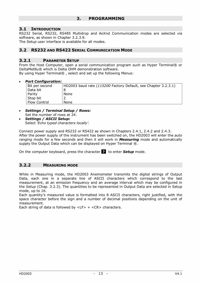
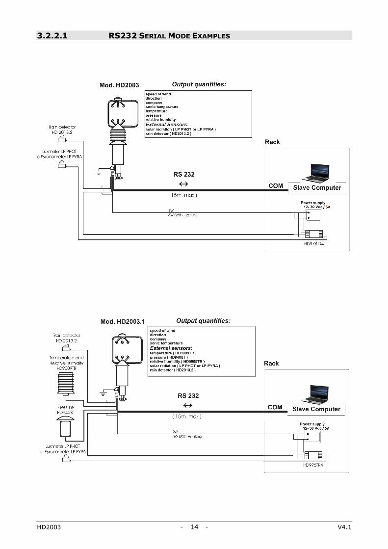
3.2.2.1 RS232 SERIAL MODE EXAMPLES
HD2003 - 15 - V4.1
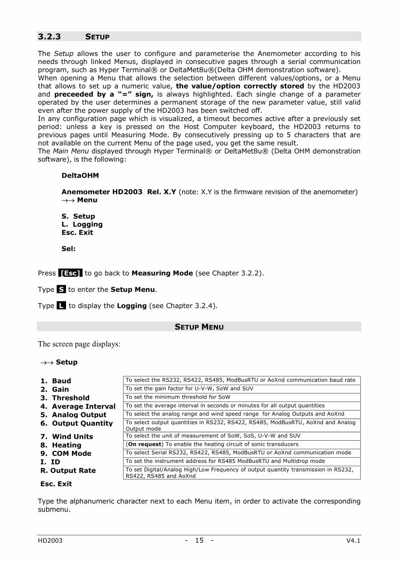
3.2.3 SETUP
The Setup allows the user to configure and parameterise the Anemometer according to his needs through linked Menus, displayed in consecutive pages through a serial communication program, such as Hyper Terminal® or DeltaMet8u®(Delta OHM demonstration software). When opening a Menu that allows the selection between different values/options, or a Menu that allows to set up a numeric value, the value/option correctly stored by the HD2003 and preceeded by a “=” sign, is always highlighted. Each single change of a parameter operated by the user determines a permanent storage of the new parameter value, still valid even after the power supply of the HD2003 has been switched off. In any configuration page which is visualized, a timeout becomes active after a previously set period: unless a key is pressed on the Host Computer keyboard, the HD2003 returns to previous pages until Measuring Mode. By consecutively pressing up to 5 characters that are not available on the current Menu of the page used, you get the same result. The Main Menu displayed through Hyper Terminal® or DeltaMet8u® (Delta OHM demonstration software), is the following:
DeltaOHM
Anemometer HD2003 Rel. X.Y (note: X.Y is the firmware revision of the anemometer) →→ Menu S. Setup L. Logging Esc. Exit Sel:
Press [Esc] to go back to Measuring Mode (see Chapter 3.2.2). Type S to enter the Setup Menu. Type L to display the Logging (see Chapter 3.2.4).
SETUP MENU
The screen page displays: →→ Setup
1. Baud To select the RS232, RS422, RS485, ModBusRTU or AoXnd communication baud rate 2. Gain To set the gain factor for U-V-W, SoW and SUV 3. Threshold To set the minimum threshold for SoW 4. Average Interval To set the average interval in seconds or minutes for all output quantities 5. Analog Output To select the analog range and wind speed range for Analog Outputs and AoXnd 6. Output Quantity To select output quantities in RS232, RS422, RS485, ModBusRTU, AoXnd and Analog
Output mode 7. Wind Units To select the unit of measurement of SoW, SoS, U-V-W and SUV 8. Heating (On request) To enable the heating circuit of sonic transducers 9. COM Mode To select Serial RS232, RS422, RS485, ModBusRTU or AoXnd communication mode I. ID To set the instrument address for RS485 ModBusRTU and Multidrop mode R. Output Rate To set Digital/Analog High/Low Frequency of output quantity transmission in RS232,
RS422, RS485 and AoXnd Esc. Exit
Type the alphanumeric character next to each Menu item, in order to activate the corresponding submenu.
HD2003 - 16 - V4.1
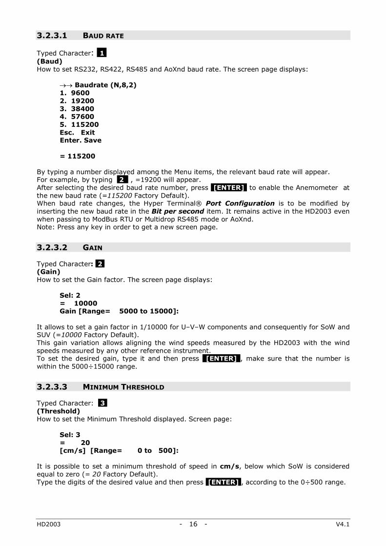
3.2.3.1 BAUD RATE
Typed Character: 1 , (Baud) How to set RS232, RS422, RS485 and AoXnd baud rate. The screen page displays:
→→ Baudrate (N,8,2) 1. 9600 2. 19200 3. 38400 4. 57600 5. 115200 Esc. Exit Enter. Save = 115200
By typing a number displayed among the Menu items, the relevant baud rate will appear. For example, by typing 2 , =19200 will appear. After selecting the desired baud rate number, press [ENTER] to enable the Anemometer at the new baud rate (=115200 Factory Default). When baud rate changes, the Hyper Terminal® Port Configuration is to be modified by inserting the new baud rate in the Bit per second item. It remains active in the HD2003 even when passing to ModBus RTU or Multidrop RS485 mode or AoXnd. Note: Press any key in order to get a new screen page.
3.2.3.2 GAIN
Typed Character: 2 , (Gain) How to set the Gain factor. The screen page displays:
Sel: 2 = 10000 Gain [Range= 5000 to 15000]:
It allows to set a gain factor in 1/10000 for U–V–W components and consequently for SoW and SUV (=10000 Factory Default). This gain variation allows aligning the wind speeds measured by the HD2003 with the wind speeds measured by any other reference instrument. To set the desired gain, type it and then press [ENTER] , make sure that the number is within the 5000÷15000 range.
3.2.3.3 MINIMUM THRESHOLD
Typed Character: 3 , (Threshold) How to set the Minimum Threshold displayed. Screen page:
Sel: 3 = 20 [cm/s] [Range= 0 to 500]:
It is possible to set a minimum threshold of speed in cm/s, below which SoW is considered equal to zero (= 20 Factory Default). Type the digits of the desired value and then press [ENTER] , according to the 0÷500 range.

HD2003 - 17 - V4.1
3.2.3.4 AVERAGE INTERVAL
Typed Character: 4 , (Average Interval) How to set the interval value in seconds or minutes in order to calculate the moving averages of all output quantities. The average interval is also the interval considered for the wind gust measurement (which however is not averaged, see the measurement description on page 3). The first screen page displays:
→→ Average Interval 1. [sec] 2. [min] Esc. Exit = [min]
The time unit of the moving average interval can be chosen, in seconds or minutes (=[min] Factory Default). After typing the number corresponding to the desired unit: … if you choose seconds:
→→ Average Interval = 2 [sec] [Range= 1 to 60]:
… if you choose minutes:
→→ Average Interval = 2 [min] [Range= 1 to 60]:
The interval value should be set between 1 and 60 (=2 Factory Default) for calculating the moving average. The moving average is the average calculated by the samples acquiring in the last time interval, equivalent to the set period in seconds or minutes. Averages can be calculated over a period from 1 to 60 seconds, or from 1 to 60 minutes. The moving average is calculated on the U-V-W and SoS components (and consequently on all the other anemometric quantities resulting from them), and for all the remaining output quantities (HD2003 Model: Pressure, Temperature, Relative Humidity). In substance, all quantities chosen as Output Data in RS232, RS422, RS485 or AoXnd as well as those chosen as Analog Outputs, are supplied by the HD2003 with values that represent the average calculated on the last time interval. The magnetic azimuth provided by the compass is excluded from moving averages. Type the digits of the desired number according to the range displayed on the screen and then press [ENTER ]. After choosing the average interval, the instrument automatically sets its Internal Refresh (Chap. 1.1). The Internal Refresh is equal to 1s if you choose the interval in seconds; if you choose it in minutes, it is equal to as many seconds as the minutes chosen. (For example, an average interval of 10min corresponds to an Internal Refresh each 10sec).
3.2.3.5 ANALOG OUTPUT FORMAT
Typed Character: 5 , (Analog Output) How to select the analog range and the wind speeds range for Analog Outputs and Analog Output Extended (AoXnd) mode. Screen page:
→→ Analog Output 1. mA-V Ranges
2. Speed Ranges Esc. Exit
HD2003 - 18 - V4.1
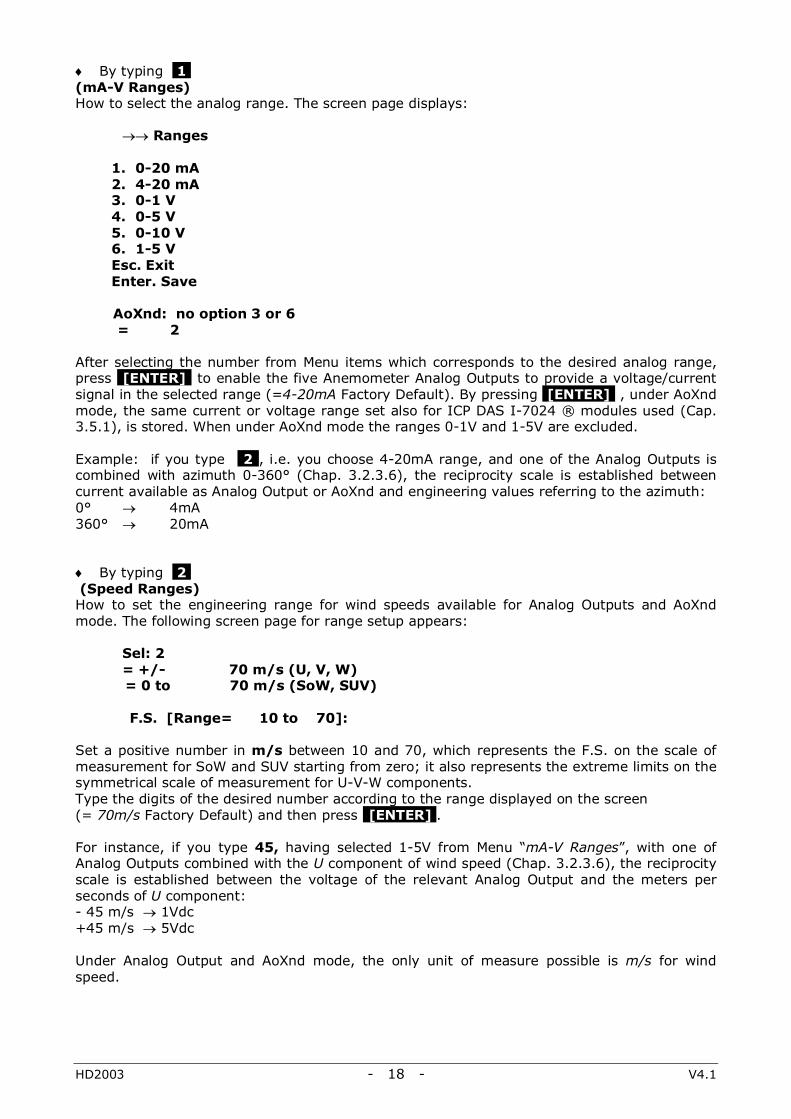
♦ By typing 1 , (mA-V Ranges) How to select the analog range. The screen page displays: →→ Ranges
1. 0-20 mA 2. 4-20 mA 3. 0-1 V 4. 0-5 V 5. 0-10 V 6. 1-5 V Esc. Exit Enter. Save
AoXnd: no option 3 or 6 = 2
After selecting the number from Menu items which corresponds to the desired analog range, press [ENTER] to enable the five Anemometer Analog Outputs to provide a voltage/current signal in the selected range (=4-20mA Factory Default). By pressing [ENTER] , under AoXnd mode, the same current or voltage range set also for ICP DAS I-7024 ® modules used (Cap. 3.5.1), is stored. When under AoXnd mode the ranges 0-1V and 1-5V are excluded. Example: if you type 2 , i.e. you choose 4-20mA range, and one of the Analog Outputs is combined with azimuth 0-360° (Chap. 3.2.3.6), the reciprocity scale is established between current available as Analog Output or AoXnd and engineering values referring to the azimuth: 0° → 4mA 360° → 20mA ♦ By typing 2 , (Speed Ranges) How to set the engineering range for wind speeds available for Analog Outputs and AoXnd mode. The following screen page for range setup appears:
Sel: 2 = +/- 70 m/s (U, V, W)
= 0 to 70 m/s (SoW, SUV) F.S. [Range= 10 to 70]: Set a positive number in m/s between 10 and 70, which represents the F.S. on the scale of measurement for SoW and SUV starting from zero; it also represents the extreme limits on the symmetrical scale of measurement for U-V-W components. Type the digits of the desired number according to the range displayed on the screen (= 70m/s Factory Default) and then press [ENTER] . For instance, if you type 45, having selected 1-5V from Menu “mA-V Ranges”, with one of Analog Outputs combined with the U component of wind speed (Chap. 3.2.3.6), the reciprocity scale is established between the voltage of the relevant Analog Output and the meters per seconds of U component: - 45 m/s → 1Vdc +45 m/s → 5Vdc Under Analog Output and AoXnd mode, the only unit of measure possible is m/s for wind speed.
HD2003 - 19 - V4.1
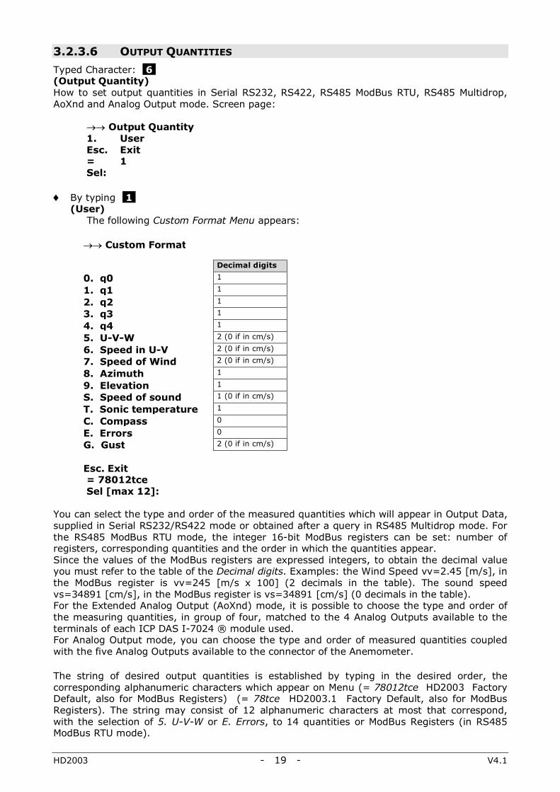
3.2.3.6 OUTPUT QUANTITIES Typed Character: 6 , (Output Quantity) How to set output quantities in Serial RS232, RS422, RS485 ModBus RTU, RS485 Multidrop, AoXnd and Analog Output mode. Screen page:
→→ Output Quantity 1. User Esc. Exit = 1 Sel:
♦ By typing 1 ,
(User) The following Custom Format Menu appears:
→→ Custom Format
Decimal digits
0. q0 1
1. q1 1
2. q2 1
3. q3 1
4. q4 1
5. U-V-W 2 (0 if in cm/s)
6. Speed in U-V 2 (0 if in cm/s)
7. Speed of Wind 2 (0 if in cm/s)
8. Azimuth 1
9. Elevation 1
S. Speed of sound 1 (0 if in cm/s)
T. Sonic temperature 1
C. Compass 0
E. Errors 0
G. Gust 2 (0 if in cm/s)
Esc. Exit
= 78012tce Sel [max 12]:
You can select the type and order of the measured quantities which will appear in Output Data, supplied in Serial RS232/RS422 mode or obtained after a query in RS485 Multidrop mode. For the RS485 ModBus RTU mode, the integer 16-bit ModBus registers can be set: number of registers, corresponding quantities and the order in which the quantities appear. Since the values of the ModBus registers are expressed integers, to obtain the decimal value you must refer to the table of the Decimal digits. Examples: the Wind Speed vv=2.45 [m/s], in the ModBus register is vv=245 [m/s x 100] (2 decimals in the table). The sound speed vs=34891 [cm/s], in the ModBus register is vs=34891 [cm/s] (0 decimals in the table). For the Extended Analog Output (AoXnd) mode, it is possible to choose the type and order of the measuring quantities, in group of four, matched to the 4 Analog Outputs available to the terminals of each ICP DAS I-7024 ® module used. For Analog Output mode, you can choose the type and order of measured quantities coupled with the five Analog Outputs available to the connector of the Anemometer. The string of desired output quantities is established by typing in the desired order, the corresponding alphanumeric characters which appear on Menu (= 78012tce HD2003 Factory Default, also for ModBus Registers) (= 78tce HD2003.1 Factory Default, also for ModBus Registers). The string may consist of 12 alphanumeric characters at most that correspond, with the selection of 5. U-V-W or E. Errors, to 14 quantities or ModBus Registers (in RS485 ModBus RTU mode).
HD2003 - 20 - V4.1
SERIAL RS232, RS422, RS485 MULTIDROP AND MODBUS RTU MODE
For output quantities format in Serial RS232 and RS422 modes see Chapter 3.2.2 Measuring mode. For RS485 Multidrop mode see Chapter 3.3.2 HD2003 Communication Protocol. The output quantities will be available in the digital Output Data in the same order as they have been chosen in the string. For output quantities format in the HD2003 ModBus registers see Chapter 3.3.3 RS485 ModBus RTU Parameter Setup.
ANALOG OUTPUT MODE
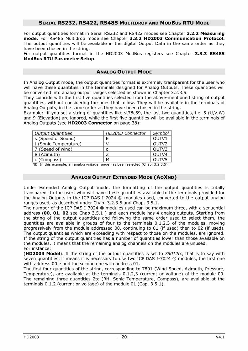
In Analog Output mode, the output quantities format is extremely transparent for the user who will have these quantities in the terminals designed for Analog Outputs. These quantities will be converted into analog output ranges selected as shown in Chapter 3.2.3.5. They coincide with the first five quantities selected from the above-mentioned string of output quantities, without considering the ones that follow. They will be available in the terminals of Analog Outputs, in the same order as they have been chosen in the string. Example: if you set a string of quantities like st78c59, the last two quantities, i.e. 5 (U,V,W) and 9 (Elevation) are ignored, while the first five quantities will be available in the terminals of Analog Outputs (see HD2003 Connector on page 38):
Output Quantities HD2003 Connector Symbol s (Speed of Sound) E OUTV1 t (Sonic Temperature) V OUTV2 7 (Speed of wind) c OUTV3 8 (Azimuth) Z OUTV4 c (Compass) M OUTV5
NB: In this example, an analog voltage range has been selected (Chap. 3.2.3.5).
ANALOG OUTPUT EXTENDED MODE (AOXND)
Under Extended Analog Output mode, the formatting of the output quantities is totally transparent to the user, who will have these quantities available to the terminals provided for the Analog Outputs in the ICP DAS I-7024 ® modules used, converted to the output analog ranges used, as described under Chap. 3.2.3.5 and Chap. 3.5.1. The number of the ICP DAS I-7024 ® modules used can be maximum three, with a sequential address (00, 01, 02 see Chap 3.5.1 ) and each module has 4 analog outputs. Starting from the string of the output quantities and following the same order used to select them, the quantities are available in groups of four to the terminals 0,1,2,3 of the modules, moving progressively from the module addressed 00, continuing to 01 (if used) then to 02 (if used). The output quantities which are exceeding with respect to those on the modules, are ignored. If the string of the output quantities has a number of quantities lower than those available on the modules, it means that the remaining analog channels on the modules are unused. For instance: (HD2003 Model). If the string of the output quantities is set to 78012tc, that is to say with seven quantities, it means it is necessary to use two ICP DAS I-7024 ® modules, the first one with address 00 e and the second one with address 01. The first four quantities of the string, corresponding to 7801 (Wind Speed, Azimuth, Pressure, Temperature), are available at the terminals 0,1,2,3 (current or voltage) of the module 00. The remaining three quantities 2tc (RH, Sonic Temperature, Compass), are available at the terminals 0,1,2 (current or voltage) of the module 01 (Cap. 3.5.1).

HD2003 - 21 - V4.1
CUSTOM FORMAT MENU
By typing: 0 , (q0)
1 , (q1)
2 , (q2)
3 , (q3)
4 , (q4)
(HD2003 Model). The arbitrary selection of 0 , 1 , 2 , allows to include the measurement of an additional meteorological quantity, in the output quantities. In the HD2003 Model, the following correspondence exists: q0 → Pressure (600 ÷ 1100mbar) q1 → Temperature (-40 ÷ 60°C ) q2 → Relative Humidity ( 0 ÷ 100% ) q3 → Optional q4 → Optional Therefore, if you type characters 0 (referring to Pressure), 1 (referring to Temperature) 2 (referring to Relative Humidity), you can add these measurements to output quantities in the desired order. (On request) Additional output quantities (see figure Chap. 3.2.2.1): (HD2003 Model). When you place your order, you can combine the two optional quantities q3 and q4, with two 0-1V external sensors connectable to the Anemometer. Thus, two additional measurements are added to the output quantities already available in the HD2003. Quantities q0, q1, q2 are already combined with Pressure, Temperature, Relative Humidity respectively. (HD2003.1 Model). When ordering, you can combine additional quantities q0, q1, q2, q3, q4, with five 0-1V external sensors connectable to the Anemometer. Thus, five additional measurements are added to output quantities of the HD2003.1. By typing 5 , (U-V-W) Intensity with sign of the three Cartesian components U-V-W of wind speed. (Orientation B, see Drawing DWG1HD2003 page 41). Sign + appears if the component measured is in the same direction of the standard reference, otherwise sign – appears. The unit of measurement is the same as for SoW. If you use them as Analog Outputs and AoXnd, you can set the engineering F.S. (Chap. 3.2.3.5), otherwise it is fixed (+/- 70 m/s). By typing 6 , (Speed in U-V) SUV Intensity, in the same unit of measurement as for SoW. (Orientation B, see Drawing DWG1HD2003 page 41). If you use it as Analog Output and AoXnd, you can set the engineering F.S. (Chap. 3.2.3.5), otherwise it is fixed (0 ÷ 70 m/s). By typing 7 , (Speed of Wind) SoW intensity, with unit of measurement setting as shown in Chapter 3.2.3.7. If you use it as Analog Output and AoXnd, you can set the engineering F.S. (Chap. 3.2.3.5), otherwise it is fixed (0 ÷ 70 m/s). By typing 8 , (Azimuth) Azimuth angle amplitude, considered as shown in Chapter 1.1 and Chapter 2.3. Range: 0 ÷ 360°.
HD2003 - 22 - V4.1
By typing 9 , (Elevation) Elevation angle amplitude, considered as shown in Chapter 1.1. Range: +/- 60°. By typing S , (Speed of sound) SoS in the same unit of measurement as for SoW. Range: 0 ÷ 400 m/s. By typing T , (Sonic temperature) Sonic Temperature calculated by SoS in °C. Range: -40 ÷60°C. By typing C , (Compass) Magnetic azimuth angle, provided by the compass as shown in Chapter 1.1 and Chapter 2.3. Range: 0 ÷ 3600 /10°. By typing E , (Errors) In the Output Data, three numbers will appear from left to right corresponding to: ♦ Error code ♦ Previous error code ♦ Number of invalid measurements. NOTE: The option Errors should not be used under Analog Output and AoXnd mode. Error Codes Table The error code consists of two digits: - The one referring to tens, identifies the sonic transducers with possible anomaly.
Sonic transducers are grouped in pairs of facing elements. For the first pair, the upper transducer is next to the HD2003 metallic support which indicates the North direction. The other pairs follow anti-clockwise. (See Drawing DWG1HD2003.1 page 42, numbering 1,2,3 in “Orientation B”). First pair of transducers: code 1 for lower transducer, 2 for the upper one. Second pair of transducers: code 3 for lower transducer, 4 for the upper one. Third pair of transducers: code 5 for lower transducer, 6 for the upper one. Code 7 is combined with the compass.
- The one referring to units highlights the kind of anomaly: Code Anomaly 0 None (combined with 0 for transducer too) 1 Electrical interruption transducer circuit. Transducer’s break. Obstruction of the path 2,5,7 Time anomaly or wave amplitude anomaly of ultrasonic pulse Others Internal codes
Example: If there is an anomaly in transducer n. 4, due to a physical obstruction in the measurement volume, which brings to the rejection of 2 raw measurements during a measure loop, in the Output Data string the following set of three numbers appears: 41 0 2 Without anomalies: 0 0 0 By typing G , (Wind Gust) Wind Gust in the same unit of measurement as for SoW.

HD2003 - 23 - V4.1
3.2.3.7 UNIT OF MEASUREMENT Typed Character: 7 , (Wind Units) How to select the unit of measurement. The screen page will display:
→→ Wind Units 1. m/s Meters per second 2. cm/s Centimetres per second 3. km/h Kilometres per hour 4. knots Knots 5. mph Miles per hour Esc. Exit Enter. Save
= m/s From the Menu, you select the unit for SoW and consequently for SoS, U-V-W and SUV. By typing a number chosen from Menu items , the corresponding unit of measurement will be displayed. For example, by typing 3 , =km/h will appear. After selecting the desired unit, press [ENTER] to enable the Anemometer to the new unit of measurement; this unit will be stored permanently until a new configuration is given (=m/s Factory Default). Under Analog Output and AoXnd mode, the only unit of measure possible for the wind speed is m/s.
3.2.3.8 SONIC TRANSDUCER HEATING This function is provided on request, and refers just to HD2003.R and HD2003.1.R models supplied with sonic transducer heating circuit. The climatic conditions which make it necessary to use the Heaters Option are indicated in Chapter 1.2.1. Typed Character: 8 , (Heating) How to enable the sonic transducer heating circuit. Screen page:
Sel: 8 = Y Enable Heat(y/n):
You can enable (by typing y or Y ) or disable (by typing n o N ) the circuit which controls the sonic transducer heating in severe climatic conditions (=Y Factory Default). Heating prevents ice formation or the deposit of sleet on sonic transducers, and activates the dissolution of the deposit of snow/sleet in the sonic transducers, guaranteeing their correct functioning.
3.2.3.9 RS232, RS422, RS485, MODBUS RTU AND AOXND COMMUNICATION MODE Typed Character: 9 , (COMM Mode) How to select Serial RS232, RS422, RS485 ModBus RTU, RS485 Multidrop or AoXnd Communication Mode. Screen page:
→→ COMM Mode 1. RS232 2. RS485 3. RS422 4. AoXnd Esc. Exit Enter. Save =RS232
HD2003 - 24 - V4.1
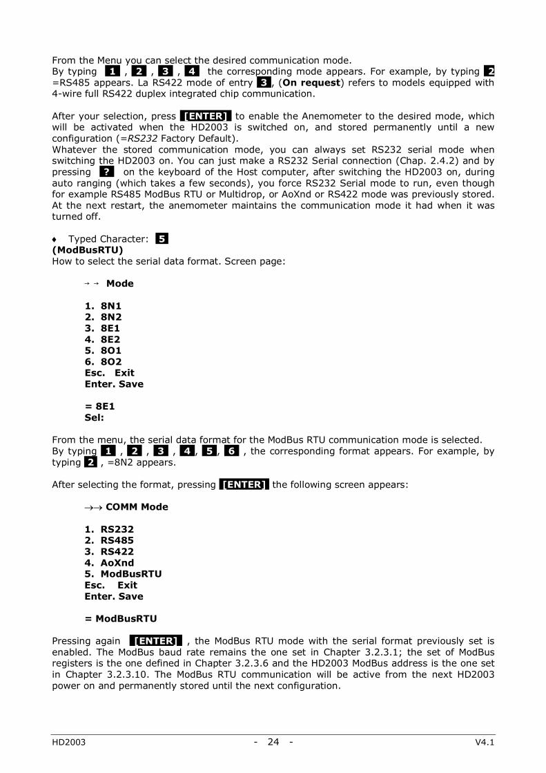
From the Menu you can select the desired communication mode. By typing 1 , 2 , 3 , 4 the corresponding mode appears. For example, by typing 2 =RS485 appears. La RS422 mode of entry 3 , (On request) refers to models equipped with 4-wire full RS422 duplex integrated chip communication. After your selection, press [ENTER] to enable the Anemometer to the desired mode, which will be activated when the HD2003 is switched on, and stored permanently until a new configuration (=RS232 Factory Default). Whatever the stored communication mode, you can always set RS232 serial mode when switching the HD2003 on. You can just make a RS232 Serial connection (Chap. 2.4.2) and by pressing ? on the keyboard of the Host computer, after switching the HD2003 on, during auto ranging (which takes a few seconds), you force RS232 Serial mode to run, even though for example RS485 ModBus RTU or Multidrop, or AoXnd or RS422 mode was previously stored. At the next restart, the anemometer maintains the communication mode it had when it was turned off. ♦ Typed Character: 5 , (ModBusRTU) How to select the serial data format. Screen page: Mode 1. 8N1 2. 8N2 3. 8E1 4. 8E2 5. 8O1 6. 8O2 Esc. Exit Enter. Save = 8E1 Sel: From the menu, the serial data format for the ModBus RTU communication mode is selected. By typing 1 , 2 , 3 , 4 , 5 , 6 , the corresponding format appears. For example, by typing 2 , =8N2 appears. After selecting the format, pressing [ENTER] the following screen appears:
→→ COMM Mode 1. RS232 2. RS485 3. RS422 4. AoXnd 5. ModBusRTU Esc. Exit Enter. Save
= ModBusRTU
Pressing again [ENTER] , the ModBus RTU mode with the serial format previously set is enabled. The ModBus baud rate remains the one set in Chapter 3.2.3.1; the set of ModBus registers is the one defined in Chapter 3.2.3.6 and the HD2003 ModBus address is the one set in Chapter 3.2.3.10. The ModBus RTU communication will be active from the next HD2003 power on and permanently stored until the next configuration.
HD2003 - 25 - V4.1
3.2.3.10 IDENTICODE
Typed Character: I , (ID) How to set the HD2003 address for RS485 ModBus RTU or Multidrop mode. Screen page:
Sel: I = 1 Identicode
Type any alphanumeric character, (0,1,2…9,a,b,…z,A,B,…Z) which will identify univocally the Anemometer (=1 Factory Default). The identicode is used in RS485 Multidrop communication mode in order to address the HD2003 Anemometers used in a two-wired Multidrop network.
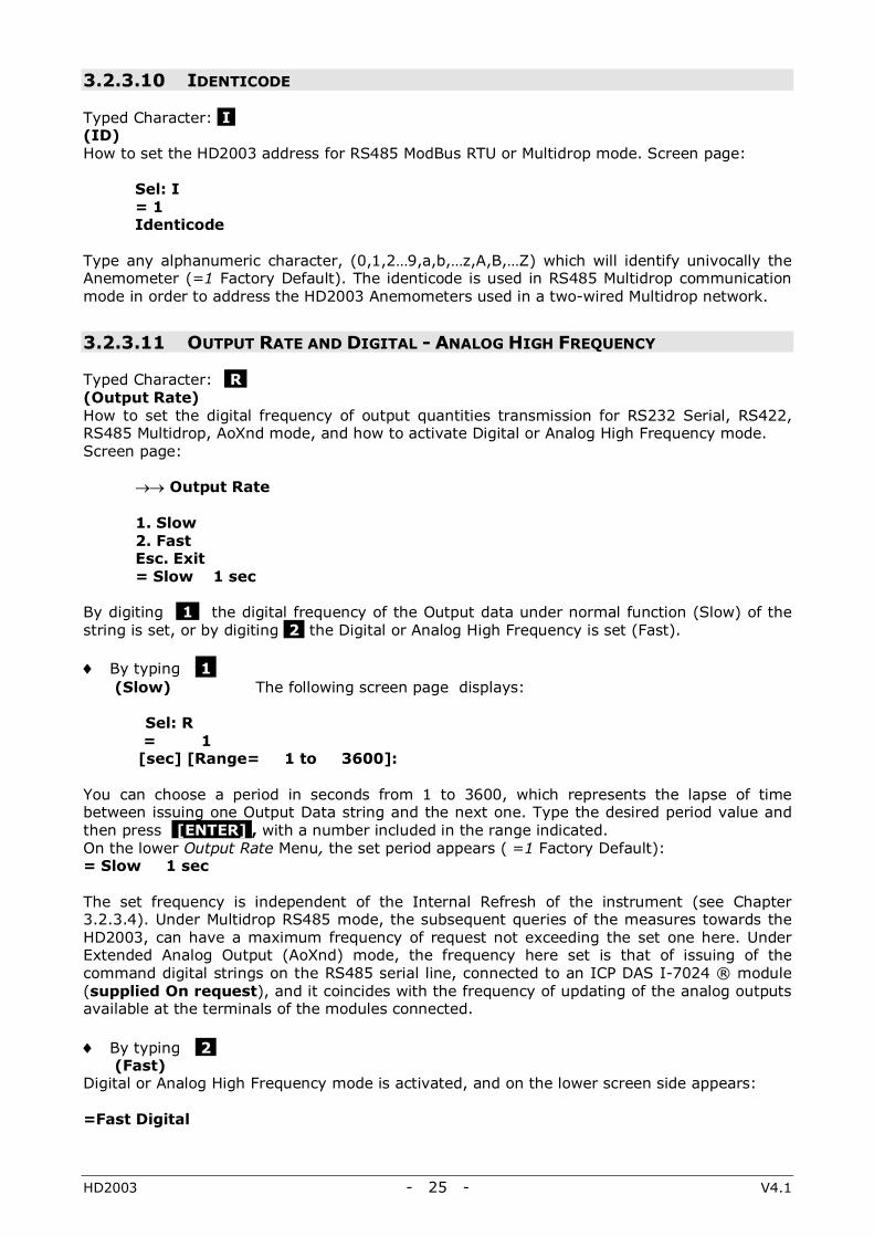
3.2.3.11 OUTPUT RATE AND DIGITAL - ANALOG HIGH FREQUENCY
Typed Character: R , (Output Rate) How to set the digital frequency of output quantities transmission for RS232 Serial, RS422, RS485 Multidrop, AoXnd mode, and how to activate Digital or Analog High Frequency mode. Screen page:
→→ Output Rate 1. Slow 2. Fast Esc. Exit = Slow 1 sec
By digiting 1 the digital frequency of the Output data under normal function (Slow) of the string is set, or by digiting 2 the Digital or Analog High Frequency is set (Fast)., ♦ By typing 1 ,
(Slow) The following screen page displays: Sel: R = 1 [sec] [Range= 1 to 3600]: You can choose a period in seconds from 1 to 3600, which represents the lapse of time between issuing one Output Data string and the next one. Type the desired period value and then press [ENTER] , with a number included in the range indicated. On the lower Output Rate Menu, the set period appears ( =1 Factory Default): = Slow 1 sec The set frequency is independent of the Internal Refresh of the instrument (see Chapter 3.2.3.4). Under Multidrop RS485 mode, the subsequent queries of the measures towards the HD2003, can have a maximum frequency of request not exceeding the set one here. Under Extended Analog Output (AoXnd) mode, the frequency here set is that of issuing of the command digital strings on the RS485 serial line, connected to an ICP DAS I-7024 ® module (supplied On request), and it coincides with the frequency of updating of the analog outputs available at the terminals of the modules connected. ♦ By typing 2 ,
(Fast) Digital or Analog High Frequency mode is activated, and on the lower screen side appears: =Fast Digital

HD2003 - 26 - V4.1
Under Digital High Frequency, the Output Data string in Serial RS232 or RS422 mode, is supplied at a fixed 50Hz frequency under the following conditions:
Baud rate bit/s Frequency / measurement quantities 115200 50Hz / 4
A number of quantities higher than four or baud rates lower than 115200 bit/s, determine emission frequencies of Output data, lower than 50Hz. Under Multidrop RS485 mode, the option Fast has no effect, because the Digital High Frequency under RS485 is achieved by a command (Chap. 3.3.2.3). The Analog High Frequency is available only in the AoXnd communication mode. It allows obtaining the voltage or current analog output of the measuring quantities under interest, at a frequency from 5Hz to 20Hz and for a maximum number of requested quantities, according to the baudrate of the command digital strings in the RS485 line:
Baud rate bit/s Frequency / measurement quantities 9600 5Hz / 4 19200 10Hz / 4 38400 10Hz / 10 57600 20Hz / 4 115200 20Hz / 7
The Digital or Analog High Frequency remains active if the instrument is switched off and on again.
3.2.4 LOGGING
As shown in Chapter 3.2.3, by typing L from the Main Menu, the following screen page will display:
Here are summarized the values set by the factory calibration, as well as the current configuration of the main parameters that can be managed by the user in Setup. Press any key to go back to the Main Menu.

HD2003 - 27 - V4.1
3.3 RS485 MULTIDROP AND RS485 MODBUS RTU COMMUNICATION MODE 3.3.1 RS485 MULTIDROP PARAMETER SETUP From the Host Computer, start an RS485 communication program made by the user, able to (Chap. 3.3.2): ♦ Transmit commands in agreement with the HD2003 Communication Protocol, towards the
Anemometers of the RS485 Multidrop network. ♦ Display and record the data and menu pages received from the queried Anemometers. The Computer Host must have an RS485 serial interface. Alternatively use an RS232/RS485 converter like ICP DAS I-7520® (supplied On Request), to be placed between the RS232 serial port of the Computer Host and the network of the HD2003. A USB-RS232 converter can be also necessary, like DeltaOHM C205M (supplied On Request). Set the following communication parameters in the RS485 communication program:
RS485 communication program parameters: Bit per second Data bit Parity Stop bit Flow Control
baud rate of each HD2003 in the network 8 None 2 None
Before connecting HD2003 Anemometers in the network, set the baud rate and identicode of each one, using the RS232 Serial Communication mode, (see Chapters 2.4.1 and 2.4.2 for electrical connections). The baud rate, the same for all the HD2003 units in the network, is selected following the Chapter 3.2.3.1 instructions. The identicode must be different for each HD2003 unit in the network, and it’s selected following the Chapter 3.2.3.10 instructions.
Connect the Anemometers in the RS485 Multidrop network and set electrical connections as illustrated in Chapters 2.4.1 and 2.4.3. After the power is supplied, each HD2003 unit (Slave) will work on Stand by continuing to execute its normal measurement cycle, waiting for commands from the Computer Host (Master).
HD2003 - 28 - V4.1
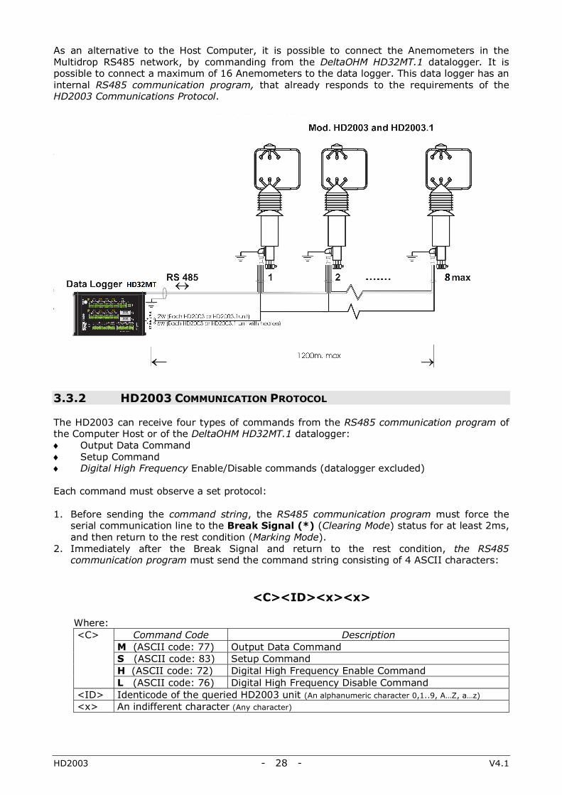
As an alternative to the Host Computer, it is possible to connect the Anemometers in the Multidrop RS485 network, by commanding from the DeltaOHM HD32MT.1 datalogger. It is possible to connect a maximum of 16 Anemometers to the data logger. This data logger has an internal RS485 communication program, that already responds to the requirements of the HD2003 Communications Protocol.
3.3.2 HD2003 COMMUNICATION PROTOCOL The HD2003 can receive four types of commands from the RS485 communication program of the Computer Host or of the DeltaOHM HD32MT.1 datalogger: ♦ Output Data Command ♦ Setup Command ♦ Digital High Frequency Enable/Disable commands (datalogger excluded) Each command must observe a set protocol: 1. Before sending the command string, the RS485 communication program must force the
serial communication line to the Break Signal (*) (Clearing Mode) status for at least 2ms, and then return to the rest condition (Marking Mode).
2. Immediately after the Break Signal and return to the rest condition, the RS485 communication program must send the command string consisting of 4 ASCII characters:
<C><ID><x><x>
Where: <C> Command Code Description
M (ASCII code: 77) Output Data Command S (ASCII code: 83) Setup Command H (ASCII code: 72) Digital High Frequency Enable Command L (ASCII code: 76) Digital High Frequency Disable Command
<ID> Identicode of the queried HD2003 unit (An alphanumeric character 0,1..9, A…Z, a…z) <x> An indifferent character (Any character)
HD2003 - 29 - V4.1
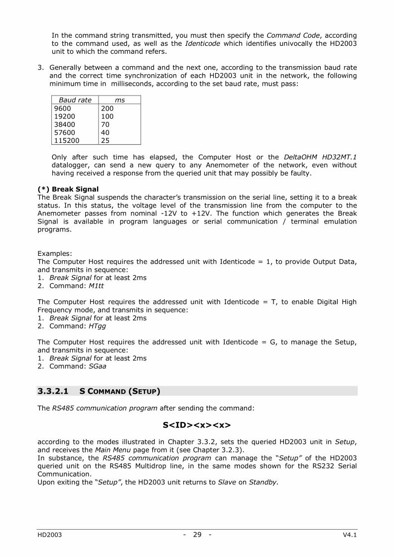
In the command string transmitted, you must then specify the Command Code, according to the command used, as well as the Identicode which identifies univocally the HD2003 unit to which the command refers.
3. Generally between a command and the next one, according to the transmission baud rate
and the correct time synchronization of each HD2003 unit in the network, the following minimum time in milliseconds, according to the set baud rate, must pass:
Baud rate ms
9600 19200 38400 57600 115200
200 100 70 40 25
Only after such time has elapsed, the Computer Host or the DeltaOHM HD32MT.1 datalogger, can send a new query to any Anemometer of the network, even without having received a response from the queried unit that may possibly be faulty.
(*) Break Signal The Break Signal suspends the character’s transmission on the serial line, setting it to a break status. In this status, the voltage level of the transmission line from the computer to the Anemometer passes from nominal -12V to +12V. The function which generates the Break Signal is available in program languages or serial communication / terminal emulation programs. Examples: The Computer Host requires the addressed unit with Identicode = 1, to provide Output Data, and transmits in sequence: 1. Break Signal for at least 2ms 2. Command: M1tt The Computer Host requires the addressed unit with Identicode = T, to enable Digital High Frequency mode, and transmits in sequence: 1. Break Signal for at least 2ms 2. Command: HTgg The Computer Host requires the addressed unit with Identicode = G, to manage the Setup, and transmits in sequence: 1. Break Signal for at least 2ms 2. Command: SGaa 3.3.2.1 S COMMAND (SETUP) The RS485 communication program after sending the command:
S<ID><x><x> according to the modes illustrated in Chapter 3.3.2, sets the queried HD2003 unit in Setup, and receives the Main Menu page from it (see Chapter 3.2.3). In substance, the RS485 communication program can manage the “Setup” of the HD2003 queried unit on the RS485 Multidrop line, in the same modes shown for the RS232 Serial Communication. Upon exiting the “Setup”, the HD2003 unit returns to Slave on Standby.
HD2003 - 30 - V4.1
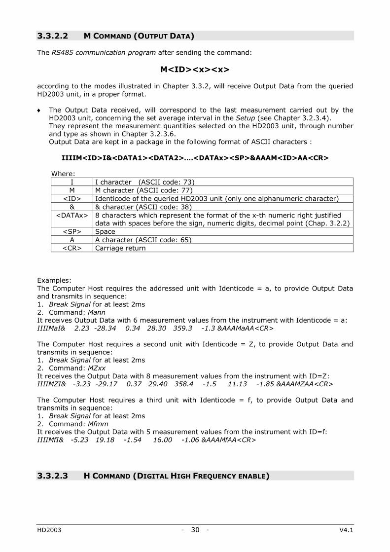
3.3.2.2 M COMMAND (OUTPUT DATA) The RS485 communication program after sending the command:
M<ID><x><x> according to the modes illustrated in Chapter 3.3.2, will receive Output Data from the queried HD2003 unit, in a proper format. ♦ The Output Data received, will correspond to the last measurement carried out by the
HD2003 unit, concerning the set average interval in the Setup (see Chapter 3.2.3.4). They represent the measurement quantities selected on the HD2003 unit, through number and type as shown in Chapter 3.2.3.6. Output Data are kept in a package in the following format of ASCII characters :
IIIIM<ID>I&<DATA1><DATA2>….<DATAx><SP>&AAAM<ID>AA<CR>
Where:
I I character (ASCII code: 73) M M character (ASCII code: 77)
<ID> Identicode of the queried HD2003 unit (only one alphanumeric character) & & character (ASCII code: 38)
<DATAx> 8 characters which represent the format of the x-th numeric right justified data with spaces before the sign, numeric digits, decimal point (Chap. 3.2.2)
<SP> Space A A character (ASCII code: 65)
<CR> Carriage return Examples: The Computer Host requires the addressed unit with Identicode = a, to provide Output Data and transmits in sequence: 1. Break Signal for at least 2ms 2. Command: Mann It receives Output Data with 6 measurement values from the instrument with Identicode = a: IIIIMaI& 2.23 -28.34 0.34 28.30 359.3 -1.3 &AAAMaAA<CR> The Computer Host requires a second unit with Identicode = Z, to provide Output Data and transmits in sequence: 1. Break Signal for at least 2ms 2. Command: MZxx It receives the Output Data with 8 measurement values from the instrument with ID=Z: IIIIMZI& -3.23 -29.17 0.37 29.40 358.4 -1.5 11.13 -1.85 &AAAMZAA<CR> The Computer Host requires a third unit with Identicode = f, to provide Output Data and transmits in sequence: 1. Break Signal for at least 2ms 2. Command: Mfmm It receives the Output Data with 5 measurement values from the instrument with ID=f: IIIIMfI& -5.23 19.18 -1.54 16.00 -1.06 &AAAMfAA<CR> 3.3.2.3 H COMMAND (DIGITAL HIGH FREQUENCY ENABLE)

HD2003 - 31 - V4.1
L COMMAND (DIGITAL HIGH FREQUENCY DISABLE) The RS485 communication program after sending the command:
H<ID><x><x> according to the modes illustrated in Chapter 3.3.2, sets the addressed HD2003 unit in the Digital High Frequency mode. In substance, the RS485 serial communication program, can subsequently query the HD2003 through command M (Output Data) at a maximum frequency of 50 Hz, under the following conditions:
Baud rate bit/s Frequency / measurement quantities 115200 50Hz / 4
The Digital High Frequency remains active if the instrument is switched off and on again. The RS485 communication program after sending the command:
L<ID><x><x> according to the modes illustrated in Chapter 3.3.2, sets the HD2003 in the normal Output Data emission mode, and disables the Digital High Frequency mode.

HD2003 - 32 - V4.1
3.3.3 RS485 MODBUS RTU PARAMETER SETUP In MODBUS-RTU mode, the HD2003 sends the measurements only on a specific request from the PC. This mode is available with the RS485 serial connection (Chapter 2.4.4).
The PC or data logger communication parameters, in accordance with the HD2003 configuration (Chapters 3.2.3.9 and 3.2.3.1), must be set as follows:
ModBus RTU communication parameters: Bits per second Data Bits Parity Stop Bits Flow Control
same as the baud rate set in the instrument (=115200 bydefault) 8 equal to the one set in the instrument (=None by default) equal to the number set in the instrument (=2 by default) None
The ModBus protocol is Master-Slave type. There is only a Master device in the network, typically the PC or a PLC or a data logger, while the other units are all Slave type. The Master unit can send commands and requests of data to the Slave devices in the network. A slave device communicates only with the Master unit, in response to a request from the latter. The direct communication between two Slave devices is not allowed and a Slave unit can not send data unless requested.
If the HD2003 does not receive the commad correctly, it does not send any response to the PC. If the PC does not receive a response within a given time (time-out), it assumes that the recipient has not received the command and and may retry the transmission or generate an error message.
The function of the ModBus protocol that can be requested by the PC to the HD2003, with the corresponding code, is shown in the following table:
Function code Function
04h Reading of HD2003 measurements
The address of the instrument (Identicode) can be set with the alphanumeric character 1,2,…9, A,B,…Z, a,b,…z (Par. 3.2.3.10); the correspondence with the ModBus address is the following: The address of the HD2003 Slave in the ModBus network must therefore be between 1 and 61 (in the case of serial RS485 Multipoint connection, see paragraph 3.3.1 for the maximum number of HD2003 that can be connected). Example: the Identicode A corresponds to 10, B corresponds to 11, a corresponds to 36, b corresponds to 37. The numbers of the ModBus registers depend on the set of registers configured in the HD2003 (Par. 3.2.3.6). Example: if the string of the output quantities is the default one, i.e. 78012tce for HD2003 or 78tce for HD2003.1, it corresponds to the following number of ModBus registers:
Output string Nr. ModBus register 78012tce 1, 2, 3, 4, 5, 6, 7, 8, 9, 10 78tce 1, 2, 3, 4, 5, 6, 7
Note: the selection e corresponds to 3 output values and therefore to 3 registers.
In the ModBus command of the Master there is the register address, which is equal to the register number decreased by one. The Master device sends the measurements reading command 04h, indicating:
• the address of the Slave HD2003 to which the command is sent; • the address of the register containing the first quantity to be read; • the number of consecutive quantities to be read.
Identicode ModBus network address 1,2,…9 1, 2,…9 A,B,…Z 10, 11,...35 a,b,...z 36, 37,...61
HD2003 - 33 - V4.1
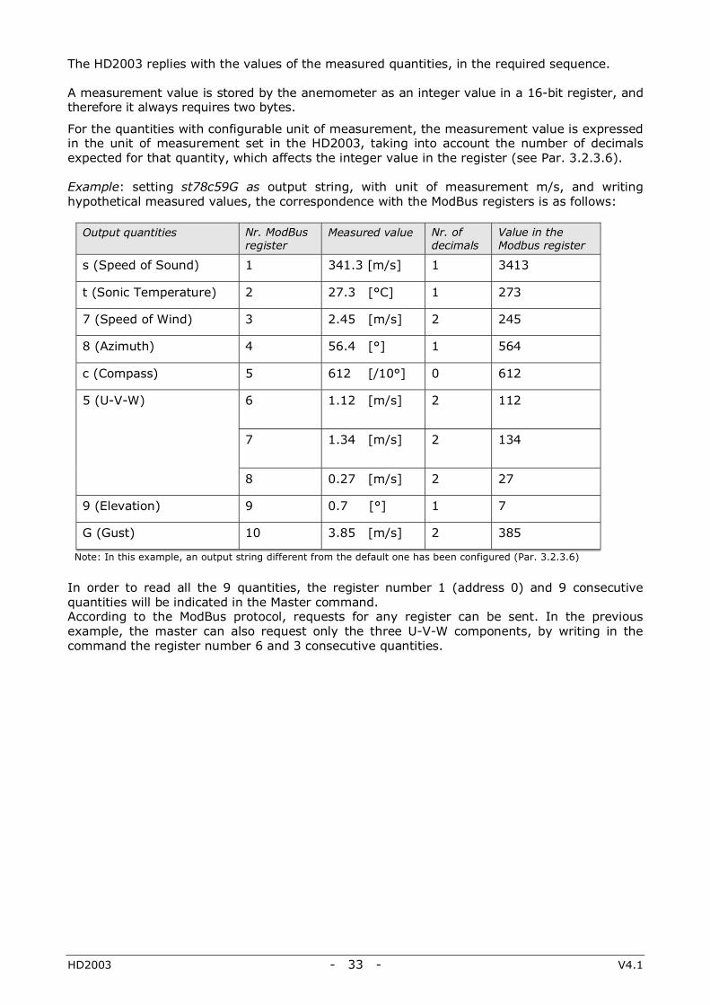
The HD2003 replies with the values of the measured quantities, in the required sequence.
A measurement value is stored by the anemometer as an integer value in a 16-bit register, and therefore it always requires two bytes.
For the quantities with configurable unit of measurement, the measurement value is expressed in the unit of measurement set in the HD2003, taking into account the number of decimals expected for that quantity, which affects the integer value in the register (see Par. 3.2.3.6). Example: setting st78c59G as output string, with unit of measurement m/s, and writing hypothetical measured values, the correspondence with the ModBus registers is as follows:
Output quantities Nr. ModBus register
Measured value Nr. of decimals
Value in the Modbus register
s (Speed of Sound) 1 341.3 [m/s] 1 3413
t (Sonic Temperature) 2 27.3 [°C] 1 273
7 (Speed of Wind) 3 2.45 [m/s] 2 245
8 (Azimuth) 4 56.4 [°] 1 564
c (Compass) 5 612 [/10°] 0 612
5 (U-V-W) 6
1.12 [m/s] 2 112
7 1.34 [m/s]
2 134
8 0.27 [m/s] 2 27
9 (Elevation) 9 0.7 [°] 1 7
G (Gust) 10 3.85 [m/s] 2 385
Note: In this example, an output string different from the default one has been configured (Par. 3.2.3.6)
In order to read all the 9 quantities, the register number 1 (address 0) and 9 consecutive quantities will be indicated in the Master command. According to the ModBus protocol, requests for any register can be sent. In the previous example, the master can also request only the three U-V-W components, by writing in the command the register number 6 and 3 consecutive quantities.
HD2003 - 34 - V4.1
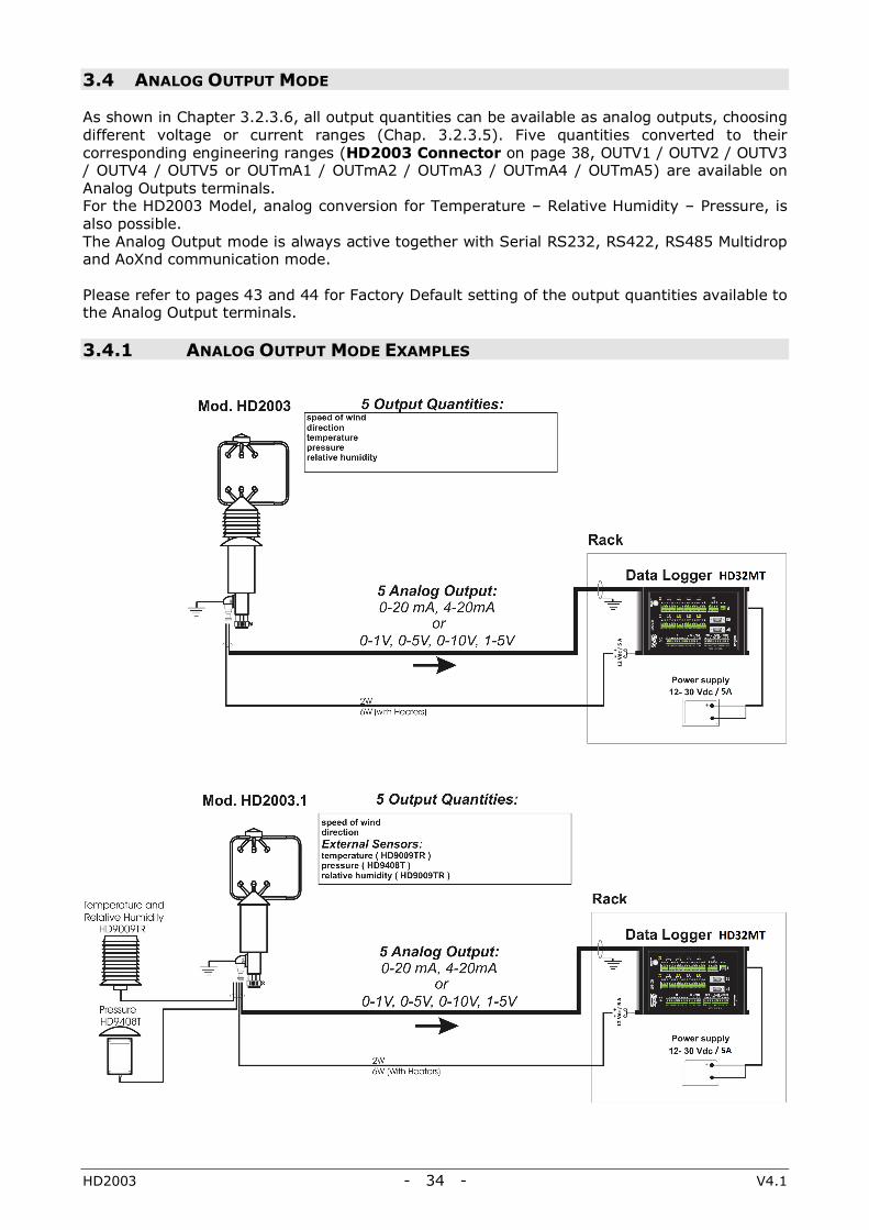
3.4 ANALOG OUTPUT MODE As shown in Chapter 3.2.3.6, all output quantities can be available as analog outputs, choosing different voltage or current ranges (Chap. 3.2.3.5). Five quantities converted to their corresponding engineering ranges (HD2003 Connector on page 38, OUTV1 / OUTV2 / OUTV3 / OUTV4 / OUTV5 or OUTmA1 / OUTmA2 / OUTmA3 / OUTmA4 / OUTmA5) are available on Analog Outputs terminals. For the HD2003 Model, analog conversion for Temperature – Relative Humidity – Pressure, is also possible. The Analog Output mode is always active together with Serial RS232, RS422, RS485 Multidrop and AoXnd communication mode. Please refer to pages 43 and 44 for Factory Default setting of the output quantities available to the Analog Output terminals. 3.4.1 ANALOG OUTPUT MODE EXAMPLES
HD2003 - 35 - V4.1
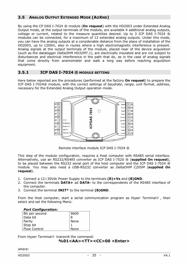
3.5 ANALOG OUTPUT EXTENDED MODE (AOXND) By using the CP DAS I-7024 ® module (On request) with the HD2003 under Extended Analog Output mode, at the output terminals of the module, are available 4 additional analog outputs, voltage or current, related to the measure quantities desired. Up to 3 ICP DAS I-7024 ® modules can be connected, for a maximum of 12 extended analog outputs. Under this mode, you can have the analog outputs at a considerable distance from the place of installation of the HD2003, up to 1200m, also in routes where a high electromagnetic interference is present. Analog signals at the output terminals of the module, placed near of the device acquisition (such as the datalogger DeltaOHM HD32MT.1), are electrically insulated and are not subject to disturbances and electrical interference in the path that do, as in the case of analog signals that come directly from anemometer and walk a long way before reaching acquisition equipment. 3.5.1 ICP DAS I-7024 ® MODULE SETTING Here below reported are the procedures (performed at the factory On request) to prepare the ICP DAS I-7024® module, with the correct settings of baudrate, range, unit format, address, necessary for the Extended Analog Output operation mode.
Remote interface module ICP DAS I-7024 ® This step of the module configuration, requires a Host computer with RS485 serial interface. Alternatively, use an RS232/RS485 converter as ICP DAS I-7520 ® (supplied On request), to be placed between the RS232 serial port of the host computer and the ICP DAS I-7024 ® module. You may also need a USB-RS232 converter as DeltaOHM C205M (supplied On request). 1. Connect a 12÷30Vdc Power Supply to the terminals (R)+Vs and (B)GND. 2. Connect the terminals DATA+ ad DATA- to the correspondents of the RS485 interface of
the computer. 3. Connect the terminal INIT* to the terminal (B)GND. From the Host computer, start a serial communication program as Hyper Terminal® , then select and set the following Menù:
Port Configuration: Bit per second Data bit Parity Stop bit Flow Control
9600 8 None 1 None
From Hyper Terminal® transmit the command:
%01<AA><TT><CC>00 <Enter> where:

HD2003 - 36 - V4.1
<AA> 00 01 02 ICP DAS I-7024 ® Modules first second third
<TT> 30 31 32 34 Range 0-20mA 4-20mA 0÷10V 0÷5V
<CC> 06 07 08 09 0A Baud rate 9600 19200 38400 57600 115200
Examples: by choosing a baudrate=19200 and a range=0÷10V and by using 1 module, the command is: %0100320700<Enter> Response: !0000320700 by choosing a baudrate=115200 and a range=4-20mA, using 3 modules, the commands are: %0100310A00<Enter> first module Response: !0000310A00 %0101310A00<Enter> second module Response: !0101310A00 %0102310A00<Enter> third module Response: !0202310A00 Remove the connection referred to in paragraph 3 above. If the baudrate has been changed, setting it to a different value from 9600 (default module), the settings are operative when the module is re-started. The module settings for baudrate, range and address (related to the number of modules), must coincide with those of the HD2003 (Chapter 3.5.2). 3.5.2 HD2003 SETTING From the Host computer select the measuring quantities to be converted into extended analog outputs, their upgrading frequency, the baudrate and the analog range, by the RS232 serial communication, (for the electrical connections see Chapters 2.4.1 and 2.4.2). Select the Extended Analog Outputs mode and the number of modules to be connected, according to the instructions at Chap. 3.2.3.9. It is possible to choose the type and the order of the measuring quantities combined with the four additional analog outputs of each module, by following the instructions on Chap. 3.2.3.6. The frequency rate for the update of the extended analog outputs can be set by following the instructions on Chap. 3.2.3.11. Baudrate, analog range and number of modules (related to the addresses of the modules), must match those set in each ICP DAS I-7024® module (previous Chap. 3.5.1). The baudrate is selected according to the instructions on Chapter 3.2.3.1, while the range is selected according to the information on Chapter 3.2.3.5. Remove the electrical connections of the RS232 communication mode and connect the Anemometer to each ICP DAS I-7024 ® module, by making the electrical connections as described on Chapters 2.4.1 and 2.4.6 for the Extended Analog Output mode. After providing electricity, the HD2003 (Master) works under Measure, by spontaneously providing command strings to the frequency set, on the RS485 serial line directly connected to each ICP DAS I-7024® remote module (Slave). Four extended analog outputs, active in the selected analog range and related to the measured quantities desired, are available at the output terminals of each module. If the measuring quantities chosen correspond to the anemometric quantities, the engineering ranges are the same preset or set by the user, according to Chapter 3.2.3.5, with the only speed of wind possible unit: m/s. Whether they included the quantities present at the analog inputs, the engineering ranges are those set by the user according to the procedures in Chapter 3.2.3.6. It is possible to change the HD2003 settings from the Host computer also on the RS485 line, by using an RS232/RS485 converter such as ICP DAS I-7520® (supplied On Request), between the RS232 serial port of the Host computer and the ICP DAS I-7024® module. From a Host Computer, start a serial communication program as Hyper Terminal® and by following the instructions on Cap. 3.2.1, send to Setup the queried HD2003 unit and then the page Main Menù will be received (Chapter 3.2.3 ).

HD2003 - 37 - V4.1
In practice, the serial communication program can handle the Setup of the queried HD2003 unit on the RS485 line, in the same way as for the RS232 and RS422 Serial Communications. After exiting the Setup, the HD2003 unit returns to Master in Measure. 3.5.3 EXAMPLES OF ANALOG OUTPUT EXTENDED MODE
The Host computer is used only to configure the ICP DAS I-7024 ® modules and the Anemometer, or for debug. The Analog Outputs of the module, converge for storage in the datalogger DeltaOHM HD32MT.1, placed close to the module. The journey of analog signals is very short, so it is not affected by electromagnetic interferences.

HD2003 - 38 - V4.1
HD2003 CONNECTOR
HD2003 - 39 - V4.1
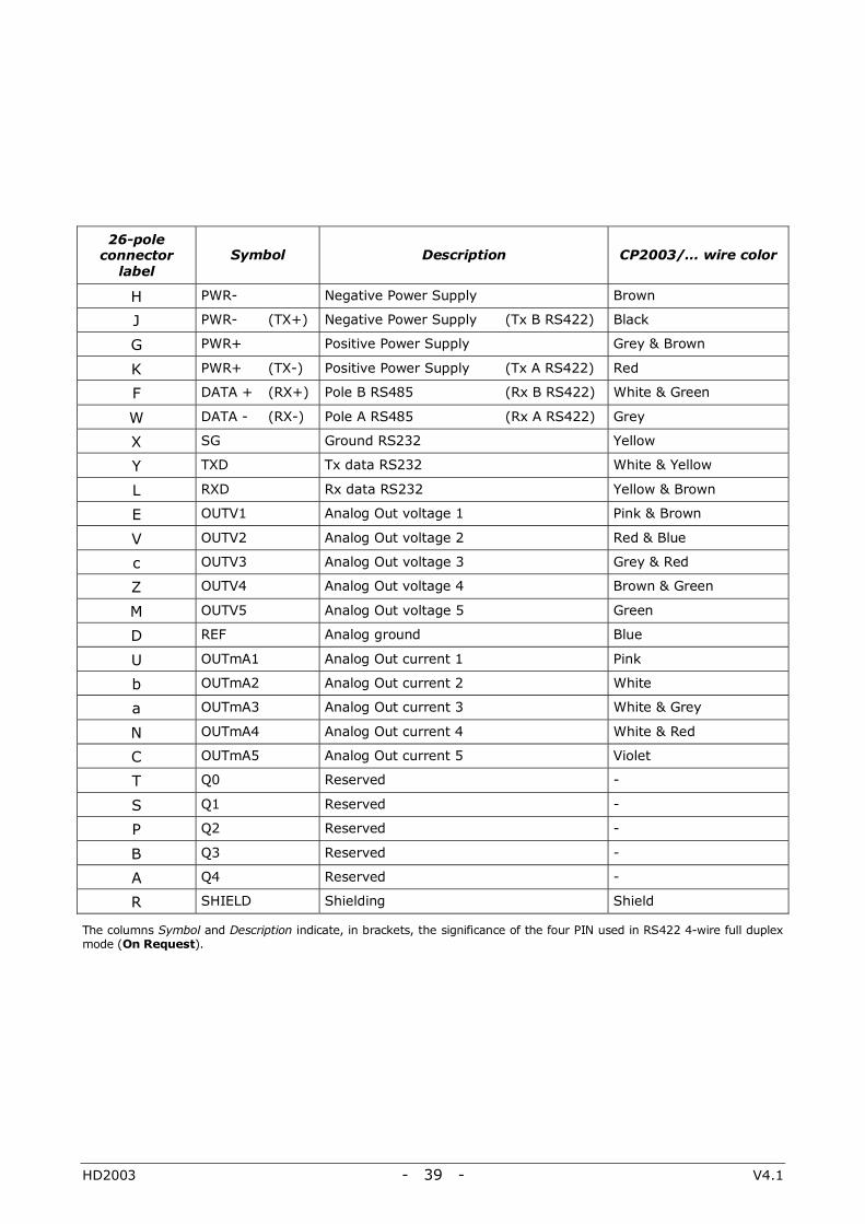
The columns Symbol and Description indicate, in brackets, the significance of the four PIN used in RS422 4-wire full duplex mode (On Request).
26-pole connector
label Symbol Description CP2003/… wire color
H PWR- Negative Power Supply Brown
J PWR- (TX+) Negative Power Supply (Tx B RS422) Black
G PWR+ Positive Power Supply Grey & Brown
K PWR+ (TX-) Positive Power Supply (Tx A RS422) Red
F DATA + (RX+) Pole B RS485 (Rx B RS422) White & Green
W DATA - (RX-) Pole A RS485 (Rx A RS422) Grey
X SG Ground RS232 Yellow
Y TXD Tx data RS232 White & Yellow
L RXD Rx data RS232 Yellow & Brown
E OUTV1 Analog Out voltage 1 Pink & Brown
V OUTV2 Analog Out voltage 2 Red & Blue
c OUTV3 Analog Out voltage 3 Grey & Red
Z OUTV4 Analog Out voltage 4 Brown & Green
M OUTV5 Analog Out voltage 5 Green
D REF Analog ground Blue
U OUTmA1 Analog Out current 1 Pink
b OUTmA2 Analog Out current 2 White
a OUTmA3 Analog Out current 3 White & Grey
N OUTmA4 Analog Out current 4 White & Red
C OUTmA5 Analog Out current 5 Violet
T Q0 Reserved -
S Q1 Reserved -
P Q2 Reserved -
B Q3 Reserved -
A Q4 Reserved -
R SHIELD Shielding Shield

HD2003 - 40 - V4.1
4. HOW TO ORDER When ordering, you should specify the Order Code, according to the type of Anemometer and the desired cable and/or plug. 4.1 ORDER CODES Order Code Description
HD2003 Three-Axis Ultrasonic Anemometer with internal sensors of Pressure Temperature – Relative Humidity
HD2003R Three-Axis Ultrasonic Anemometer with internal sensors of Pressure Temperature – Relative Humidity, with Heaters Option
HD2003.1 Three-Axis Ultrasonic Anemometer
HD2003.1R Three-Axis Ultrasonic Anemometer with Heaters Option
CP2003.5 Cable Ф=8mm, length=5m, and 26 pole shielded watertight plug (only on one end)
CP2003.10 Cable Ф=8mm, length=10m, and 26 pole shielded watertight plug (only on one end)
CP2003.15 Cable Ф=8mm, length=15m, and 26 pole shielded watertight plug (only on one end)
CP2003.20 Cable Ф=8mm, length=20m, and 26 pole shielded watertight plug (only on one end)
CP2003.30 Cable Ф=8mm, length=30m, and 26 pole shielded watertight plug (only on one end)
CP2003.C 26 pole watertight plug Tyco® 62IN-16A-16-26S-4 0445 (for plug pin, see HD2003 Connector on page 38)
RS2003 Cable with a USB connector on one side and watertight 26-pin connector on the other, with 12Vdc plug for main power supply
ICP DAS I-7024 CR® Module for Extended Analog Output mode. Indicate how many modules (up to a maximum of 3) and which configuration is needed
ICP DAS I-7520 CR® RS232/RS485 converting module for the RS485 Multidrop mode and the Extended Analog Output mode
C205M USB-RS232 converter cable with USB connector on one side and a 9-pin male connector on the other
Also, it is fundamental to specify whether any of the following is requested: ♦ HD2003 and HD2003.1 Model: the integrated circuit for RS422 4-wire full duplex
communication. ♦ HD2003 Model: to extend the output quantities by using external sensors, with analog
output signal 0-1V to be connected to the anemometer as input sensors. Specify how many sensors are used (up to a maximum of two) and their range so for linearization of the scale 0-1V.
♦ HD2003.1 Model: to extend the output quantities by using external sensors, with analog output signal 0-1V to be connected to the anemometer as input sensors. Specify how many sensors are used (up to a maximum of five) and their range so for linearization of the scale 0-1V.

HD2003 - 41 - V4.1
HD2003 - 42 - V4.1

HD2003 - 43 - V4.1
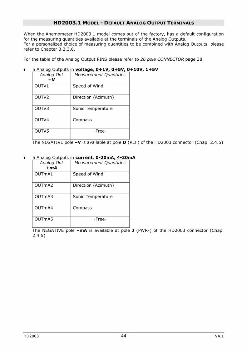
HD2003 MODEL - DEFAULT ANALOG OUTPUT TERMINALS When the Anemometer HD2003 model comes out of the factory, has a default configuration for the measuring quantities available at the terminals of the Analog Outputs. For a personalized choice of measuring quantities to be combined with Analog Outputs, please refer to Chapter 3.2.3.6. For the table of the Analog Output PINS please refer to 26 pole CONNECTOR page 38. ♦ 5 Analog Outputs in voltage, 0÷1V, 0÷5V, 0÷10V, 1÷5V
Analog Out +V
Measurement Quantities
OUTV1 Speed of Wind
OUTV2 Direction (Azimuth)
OUTV3 Pressure
OUTV4 Temperature
OUTV5 Relative Humidity
The NEGATIVE pole –V is available at the pole D (REF) of the HD2003 connector (Chap. 2.4.5)
♦ 5 Analog Outputs in current, 0-20mA, 4-20mA
Analog Out +mA
Measurement Quantities
OUTmA1 Speed of Wind
OUTmA2 Direction (Azimuth)
OUTmA3 Pressure
OUTmA4 Temperature
OUTmA5 Relative Humidity
The NEGATIVE pole –mA is available at the pole J (PWR-) of the HD2003 connector (Cap. 2.4.5)
HD2003 - 44 - V4.1
HD2003.1 MODEL - DEFAULT ANALOG OUTPUT TERMINALS When the Anemometer HD2003.1 model comes out of the factory, has a default configuration for the measuring quantities available at the terminals of the Analog Outputs. For a personalized choice of measuring quantities to be combined with Analog Outputs, please refer to Chapter 3.2.3.6. For the table of the Analog Output PINS please refer to 26 pole CONNECTOR page 38. ♦ 5 Analog Outputs in voltage, 0÷1V, 0÷5V, 0÷10V, 1÷5V
Analog Out +V
Measurement Quantities
OUTV1 Speed of Wind
OUTV2 Direction (Azimuth)
OUTV3 Sonic Temperature
OUTV4 Compass
OUTV5 -Free-
The NEGATIVE pole –V is available at pole D (REF) of the HD2003 connector (Chap. 2.4.5) ♦ 5 Analog Outputs in current, 0-20mA, 4-20mA
Analog Out +mA
Measurement Quantities
OUTmA1 Speed of Wind
OUTmA2 Direction (Azimuth)
OUTmA3 Sonic Temperature
OUTmA4 Compass
OUTmA5 -Free-
The NEGATIVE pole –mA is available at pole J (PWR-) of the HD2003 connector (Chap. 2.4.5)
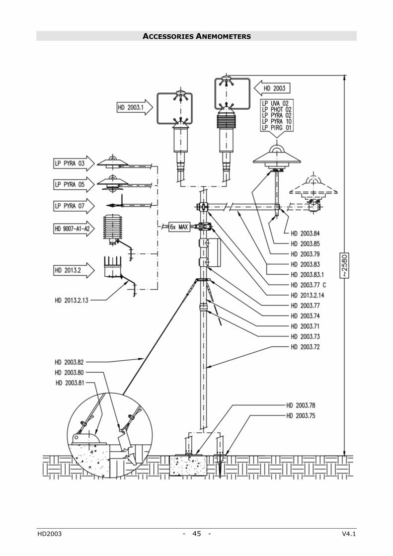
HD2003 - 45 - V4.1
ACCESSORIES ANEMOMETERS

NOTES
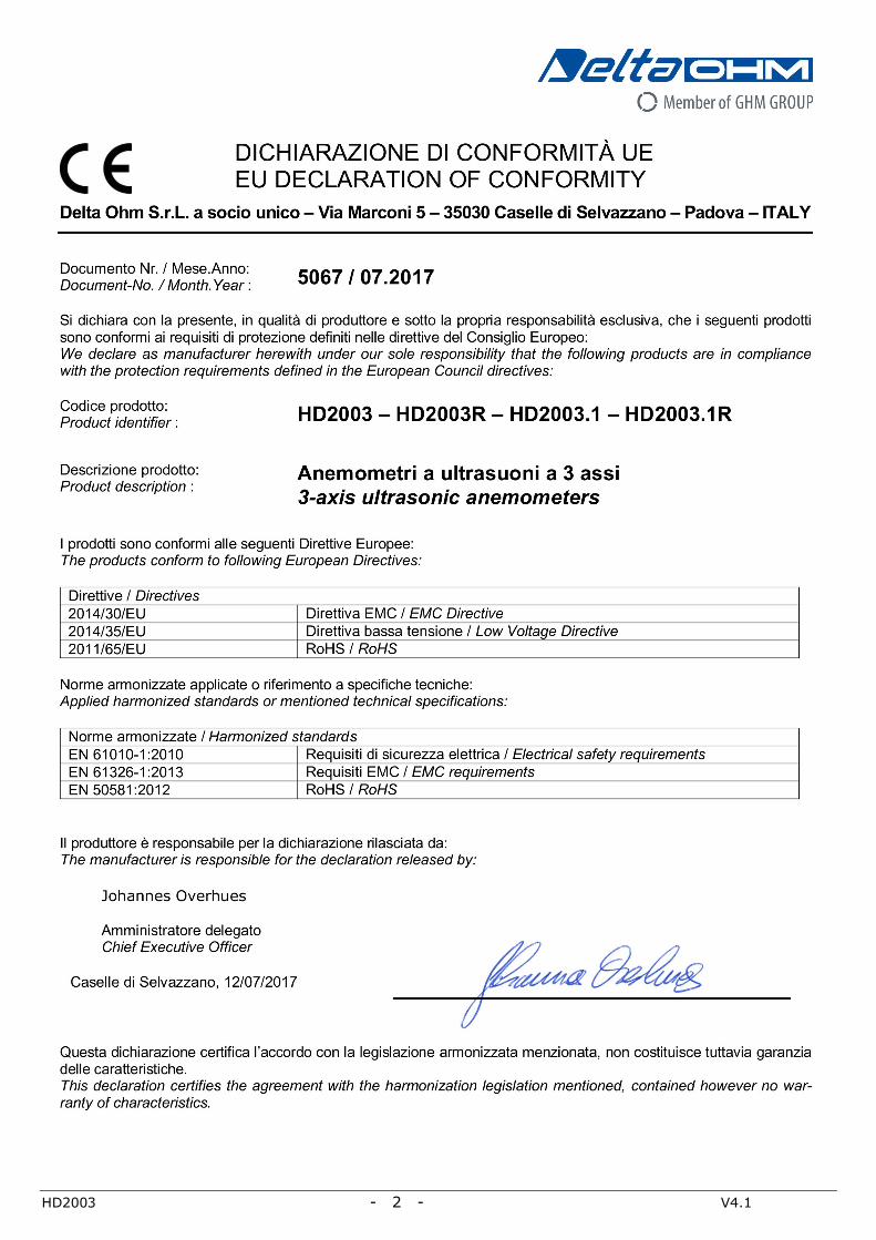
HD2003 - 2 - V4.1

GUARANTEE
TERMS OF GUARANTEE All DELTA OHM instruments are subject to accurate testing, and are guaranteed for 24 months from the date of purchase. DELTA OHM will repair or replace free of charge the parts that, within the warranty period, shall be deemed non efficient according to its own judgement. Complete replacement is excluded and no damage claims are accepted. The DELTA OHM guarantee only covers instrument repair. The guarantee is void in case of incidental breakage during transport, negligence, misuse, connection to a different voltage than that required for the appliance by the operator. Finally, a product repaired or tampered by unauthorized third parties is excluded from the guarantee. The instrument shall be returned FREE OF SHIPMENT CHARGES to your dealer. The jurisdiction of Padua applies in any dispute.
The electrical and electronic equipment marked with this symbol cannot be disposed of in public landfills. According to the Directive 2011/65/EU, the european users of electrical and electronic equipment can return it to the dealer or manufacturer upon purchase of a new one. The illegal disposal of electrical and electronic equipment is punished with an administrative fine.
This guarantee must be sent together with the instrument to our service centre. IMPORTANT: Guarantee is valid only if coupon has been correctly filled in all details.
Instrument Code: HD2003 HD2003R
HD2003.1 HD2003.1R Serial Number
RENEWALS
Date Date
Inspector Inspector
Date Date
Inspector Inspector
Date Date
Inspector Inspector
GHM GROUP – Delta OHM | Delta Ohm S.r.l. a socio unico Via Marconi 5 | 35030 Caselle di Selvazzano | Padova | ITALY Phone +39 049 8977150 | Fax +39 049 635596 www.deltaohm.com | [email protected]
The quality level of our instruments is the result of the constant development of the product. This may produce some differences between the information written in this manual and the instrument you have purchased. We cannot completely exclude the possibility of errors in the manual, for which we apologize.
The data, images and descriptions included in this manual cannot be legally asserted. We reserve the right to make changes and corrections with no prior notice.

GHM GROUP – Delta OHM | Delta Ohm S.r.l. a socio unico Via Marconi 5 | 35030 Caselle di Selvazzano | Padova | ITALY Phone +39 049 8977150 | Fax +39 049 635596 www.deltaohm.com | [email protected]
V4.1 08/03/2019