enhanced multicarrier techniques for professional ad...
TRANSCRIPT
ICT 318362 EMPhAtiC Date: 21/05/2015
ICT-EMPhAtiC Deliverable D9.4 1/45
Enhanced Multicarrier Techniques for Professional Ad‐Hoc and Cell‐Based Communications
(EMPhAtiC)
Document Number D9.4
Evaluation of the implemented communication system
Contractual date of delivery to the CEC: 28/02/2015
Actual date of delivery to the CEC: 16/03/2015
Project Number and Acronym: 257626 EMPhAtiC
Editor: Dejan Rakic
Authors: Dejan Rakic (Bitgear), Vukasin Pejovic (Bitgear),
Nikolaos Bartzoudis (CTTC), Oriol Font‐Bach (CTTC), David López Bueno (CTTC), Vidar Ringset (SINTEF), Tor André Myrvoll (SINTEF), Philippe Mege (CASSIDIAN), Laurent Martinod (CASSIDIAN), Dmitry Petrov (Magister)
Participants: CTTC, CNAM, TUT, SINTEF, CASSIDIAN, Bitgear, Magister
Workpackage: WP9
Security: Public (PU)
Nature: Report
Version: 1.2
Total Number of Pages: 45
Abstract:
This document presents the evaluation of the system‐level software simulation platform and provides the results of a performance measurement campaign of the hardware demonstrator. This demonstrator configuration consists of an FBMC transmitter, a channel emulator, an FBMC receiver and two TETRAPOL units working in parallel. Al these elements have been configured to illustrate the feasibility of coexistence with other legacy narrowband systems on the same spectral band.
Ref. Ares(2015)2205332 - 27/05/2015
ICT 318362 EMPhAtiC Date: 21/05/2015
ICT-EMPhAtiC Deliverable D9.4 2/45
Document Revision History
Version Date Author Summary of main changes
1.0 02.20.2015 Dejan Rakic (Bitgear) Initial structure of the document and main sections.
1.1 02.20.2105 ALL Rearrangement of the document structure and provision of initial text.
1.2 21.05.2015 Oriol Font Modifications in the caption of Figures 6.4 and 6.5. Inclusion of BER graphs for standalone TETRAPOL system.
ICT 318362 EMPhAtiC Date: 21/05/2015
ICT-EMPhAtiC Deliverable D9.4 3/45
Executive Summary
This document aims at evaluating the proposed broadband filter‐bank system in coexistence with primary narrowband PMR communications. Towards that end, it includes system level simulation study, which leverage the flexibility of software modelling to the analysis of complex operating scenarios. A subset of those simulation results are then experimentally validated by means of the hardware EMPhAtiC demonstrator. Furthermore, the document thoroughly evaluates the cost of physical realization of the proposed filter‐bank techniques, by targeting different prototyping approaches and considering both pure software and FPGA‐based implementations of the different baseband functionalities.

ICT 318362 EMPhAtiC Date: 21/05/2015
ICT-EMPhAtiC Deliverable D9.4 4/45
Table of Contents
1. System level simulations and demonstration of cell-based PMR system ........ 5 1.1 Simulation parameters ................................................................................. 5 1.2 Simulator and models .................................................................................. 6
1.2.1 Pathloss implementation ........................................................................ 7 1.2.2 Shadowing implementation ..................................................................... 9 1.2.3 Link to system mapping ....................................................................... 11 1.2.4 Transport block sizes ........................................................................... 13
1.3 Simulation results ..................................................................................... 14 1.4 Demonstration and NEF player .................................................................... 16
2. Hardware demonstrator ............................................................................... 19 2.1 Basic description of the hardware-demonstrator ............................................ 19 2.2 Hardware-acceleration of algorithms and building blocks ................................. 20
3. Implementation of the transmitter ............................................................... 21 3.1 Real-time SoC-based implementation of the broadband transmitter systems ...... 21
4. Implementation of the receiver .................................................................... 23 4.1 SDR-based implementation of the SISO broadband receiver ............................ 23
4.1.1 The USRP component .......................................................................... 23 4.1.2 Rate converter .................................................................................... 23 4.1.3 Preamble search ................................................................................. 24 4.1.4 Demodulation ..................................................................................... 24 4.1.5 Equalizer ............................................................................................ 24 4.1.6 Symbol demapper ............................................................................... 24 4.1.7 Conclusion ......................................................................................... 24
4.2 SDR-based implementation of the MIMO broadband receiver ........................... 25 4.2.1 USRP component ................................................................................ 25 4.2.2 Preamble search ................................................................................. 25 4.2.3 MIMO decoding ................................................................................... 26 4.2.4 Conclusion ......................................................................................... 26
5. Analysis of building blocks in the FBMC system that can be accelerated on hardware .......................................................................................................... 27
5.1 Transmitter side ........................................................................................ 27 5.1.1 Complexity comparison: CP-OFDM and FBMC .......................................... 27
5.2 Receiver side ............................................................................................ 28 5.2.1 Synchronisation module ....................................................................... 28 5.2.2 Long overlap ...................................................................................... 29 5.2.3 Long DFT ........................................................................................... 29 5.2.4 Frequency domain weighting ................................................................. 29 5.2.5 Short IDFT ......................................................................................... 30 5.2.6 Phase shifting ..................................................................................... 30 5.2.7 OQAM processing ................................................................................ 30 5.2.8 Channel Estimation .............................................................................. 30 5.2.9 Equaliser ............................................................................................ 31 5.2.10 Receiver resource usage ..................................................................... 31
5.3 Overall resource usage, transmitter and receiver ........................................... 32 6. Experimental coexistence evaluation of the EMPhAtiC demonstrator under mobile channels ............................................................................................... 33
6.1 Experimental results .................................................................................. 33 7. Conclusion .................................................................................................... 42 Glossary and definitions ................................................................................... 43 References ....................................................................................................... 45
ICT 318362 EMPhAtiC Date: 21/05/2015
ICT-EMPhAtiC Deliverable D9.4 5/45
1. System level simulations and demonstration of cell‐based PMR system System simulation is an important phase in the development of every new telecommunication technology. The main purpose of such simulative study is to evaluate the performance of a larger‐scale network that includes sufficient number of base stations and network users. All these entities are included into the same simulation setting. Thus, it becomes possible to study the effect of their interaction and inter‐dependence, such as realistic interference, user and traffic scheduling, etc. In general, with the results of such a study it is possible to achieve the following targets:
Test new and advanced features and their gains
Study wide range of scenarios
Identify bottlenecks in processes
Prevent under or over‐utilisation of resources
Safe and cheaper way to evaluate the side effects
Optimize the performance of the system
Balance expenses and improvements in user experience
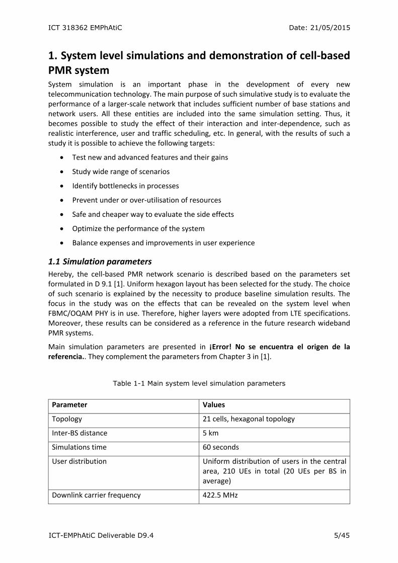
1.1 Simulation parameters
Hereby, the cell‐based PMR network scenario is described based on the parameters set formulated in D 9.1 [1]. Uniform hexagon layout has been selected for the study. The choice of such scenario is explained by the necessity to produce baseline simulation results. The focus in the study was on the effects that can be revealed on the system level when FBMC/OQAM PHY is in use. Therefore, higher layers were adopted from LTE specifications. Moreover, these results can be considered as a reference in the future research wideband PMR systems.
Main simulation parameters are presented in ¡Error! No se encuentra el origen de la referencia.. They complement the parameters from Chapter 3 in [1].
Table 1-1 Main system level simulation parameters
Parameter Values
Topology 21 cells, hexagonal topology
Inter‐BS distance 5 km
Simulations time 60 seconds
User distribution Uniform distribution of users in the central area, 210 UEs in total (20 UEs per BS in average)
Downlink carrier frequency 422.5 MHz
ICT 318362 EMPhAtiC Date: 21/05/2015
ICT-EMPhAtiC Deliverable D9.4 6/45
Bandwidth 5 MHz, 25 RBs
Pathloss model SEAMCAT Extended Hata, urban environment
Slow fading Correlated Callusen model, map‐based; Standard deviation = 9.0; Inter‐site correlation = 0.5.
UE mobility Random way‐point mobility
HO criteria A3, RSRP‐based handover
Scheduling Proportional fare
Frame structure 14 MC symbols per sub‐frame in LTE case,
15 MC symbols per sub‐frame in PMR case
Downlink traffic Constant bit rate, 2048 kbps per user, UDP traffic, full buffer, packet size = 512 kb.
FBMC distortion Trace‐based; LTE – off;
PMR – on: average, maximum scenarios
1.2 Simulator and models
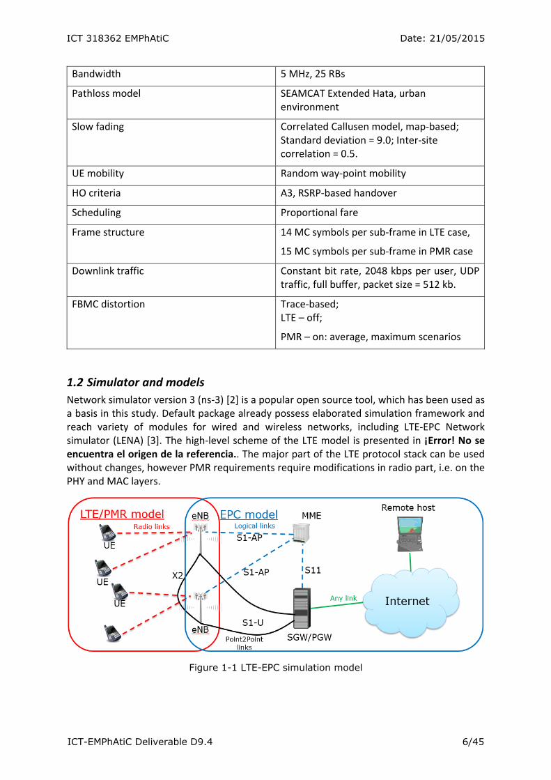
Network simulator version 3 (ns‐3) [2] is a popular open source tool, which has been used as a basis in this study. Default package already possess elaborated simulation framework and reach variety of modules for wired and wireless networks, including LTE‐EPC Network simulator (LENA) [3]. The high‐level scheme of the LTE model is presented in ¡Error! No se encuentra el origen de la referencia.. The major part of the LTE protocol stack can be used without changes, however PMR requirements require modifications in radio part, i.e. on the PHY and MAC layers.
Figure 1-1 LTE-EPC simulation model

ICT 318362 EMPhAtiC Date: 21/05/2015
ICT-EMPhAtiC Deliverable D9.4 7/45
1.2.1 Pathloss implementation
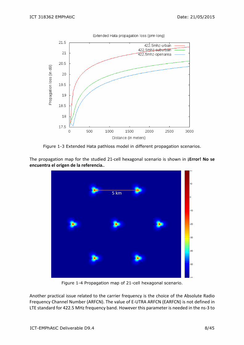
A SEAMCAT extended Hata pathloss model [4] was adopted as one of the propagation models in the ns‐3 platform. The implementation allows a selection from one of three scenarios: Open area, Suburban and Urban (¡Error! No se encuentra el origen de la referencia.). For the current study only Urban model at 422.5 MHz carrier frequency was used (¡Error! No se encuentra el origen de la referencia.).
Figure 1-2 Extended Hata pathloss at different frequencies, urban scenario.
ICT 318362 EMPhAtiC Date: 21/05/2015
ICT-EMPhAtiC Deliverable D9.4 8/45
Figure 1-3 Extended Hata pathloss model in different propagation scenarios.
The propagation map for the studied 21‐cell hexagonal scenario is shown in ¡Error! No se encuentra el origen de la referencia..
Figure 1-4 Propagation map of 21-cell hexagonal scenario.
Another practical issue related to the carrier frequency is the choice of the Absolute Radio Frequency Channel Number (ARFCN). The value of E‐UTRA ARFCN (EARFCN) is not defined in LTE standard for 422.5 MHz frequency band. However this parameter is needed in the ns‐3 to
60
-50
-40
-30
-20
-10
0
10
20
5 km
ICT 318362 EMPhAtiC Date: 21/05/2015
ICT-EMPhAtiC Deliverable D9.4 9/45
configure eNBs. Therefore the values of Uplink and Downlink EARFCN where calculated explicitly: DlEarfcn = 6625 and UlEarfcn = 24625.
1.2.2 Shadowing implementation
By default, shadowing model is quite simplistic in ns‐3. It is simulated as a log‐normal random variable, which is appropriate for static nodes only. For that reason, more elaborated correlation‐based shadowing map approach was implemented based on [5].
The main idea behind this algorithm is to generate shadowing map with the values that are correlated with its geographical neighbours. Correlation function is selected to be exponential distance dependent , 0. In general, random values with required correlations can be constructed from uncorrelated normal random variables using a Cholesky factor of correlation matrix :
, .
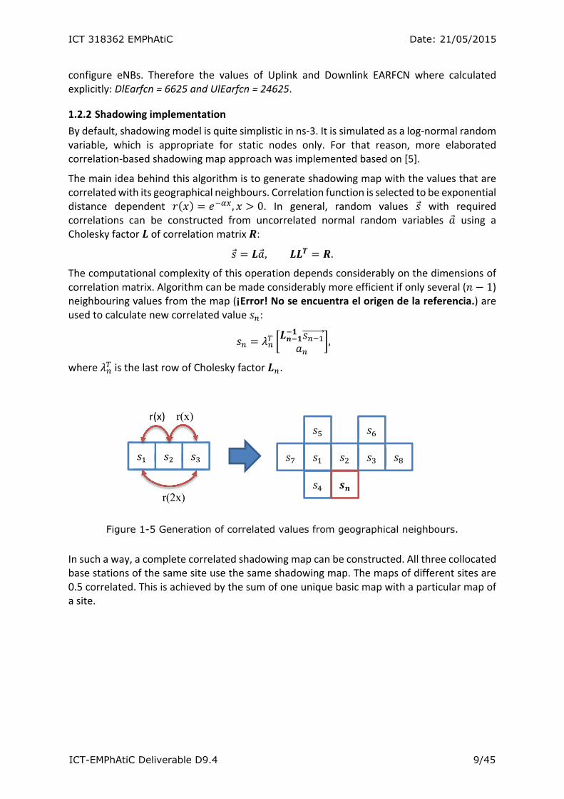
The computational complexity of this operation depends considerably on the dimensions of correlation matrix. Algorithm can be made considerably more efficient if only several ( 1) neighbouring values from the map (¡Error! No se encuentra el origen de la referencia.) are used to calculate new correlated value :
,
where is the last row of Cholesky factor .
Figure 1-5 Generation of correlated values from geographical neighbours.
In such a way, a complete correlated shadowing map can be constructed. All three collocated base stations of the same site use the same shadowing map. The maps of different sites are 0.5 correlated. This is achieved by the sum of one unique basic map with a particular map of a site.
r(x) r(x)
r(2x)
ICT 318362 EMPhAtiC Date: 21/05/2015
ICT-EMPhAtiC Deliverable D9.4 10/45
Figure 1-6 Implementation of correlated scheduling in the ns-3.
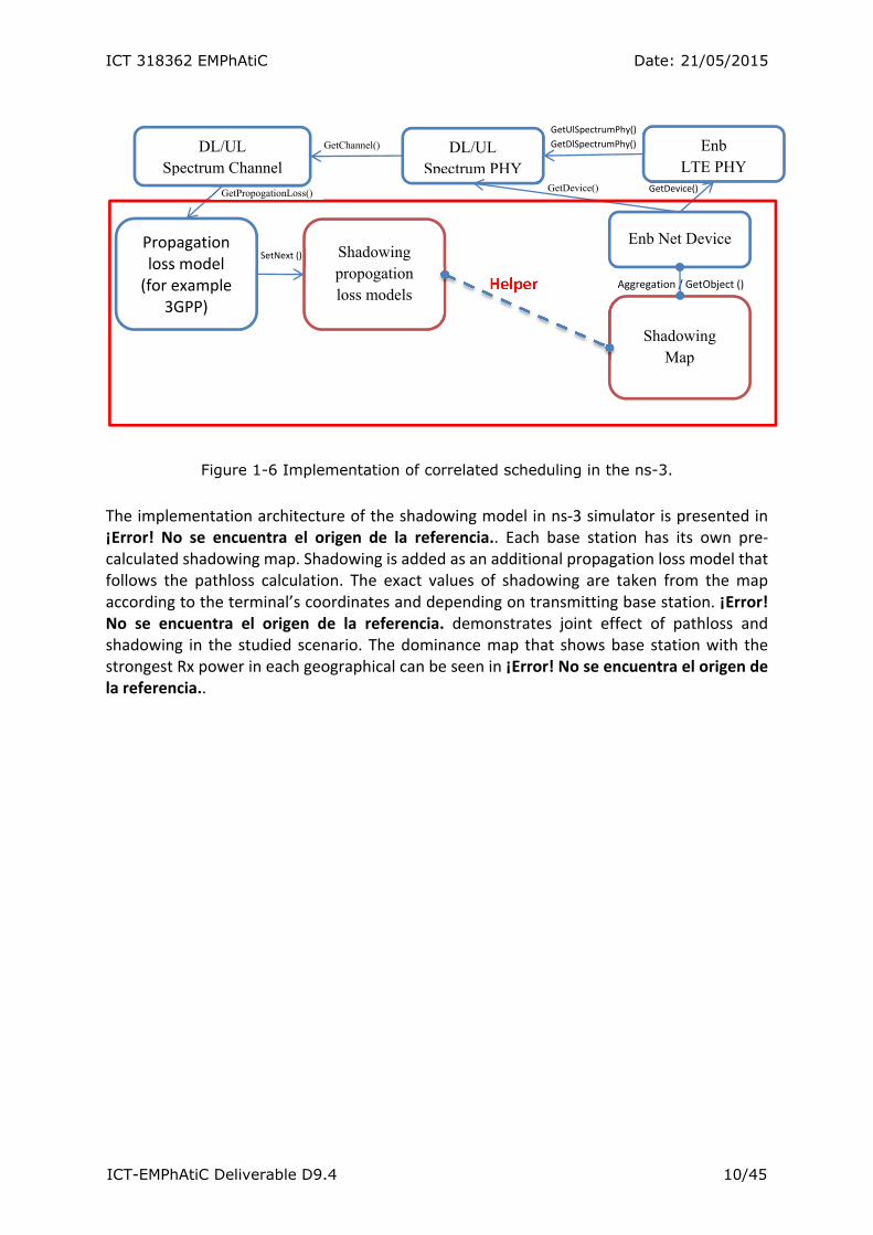
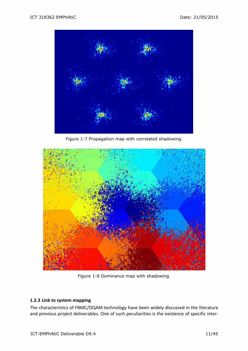
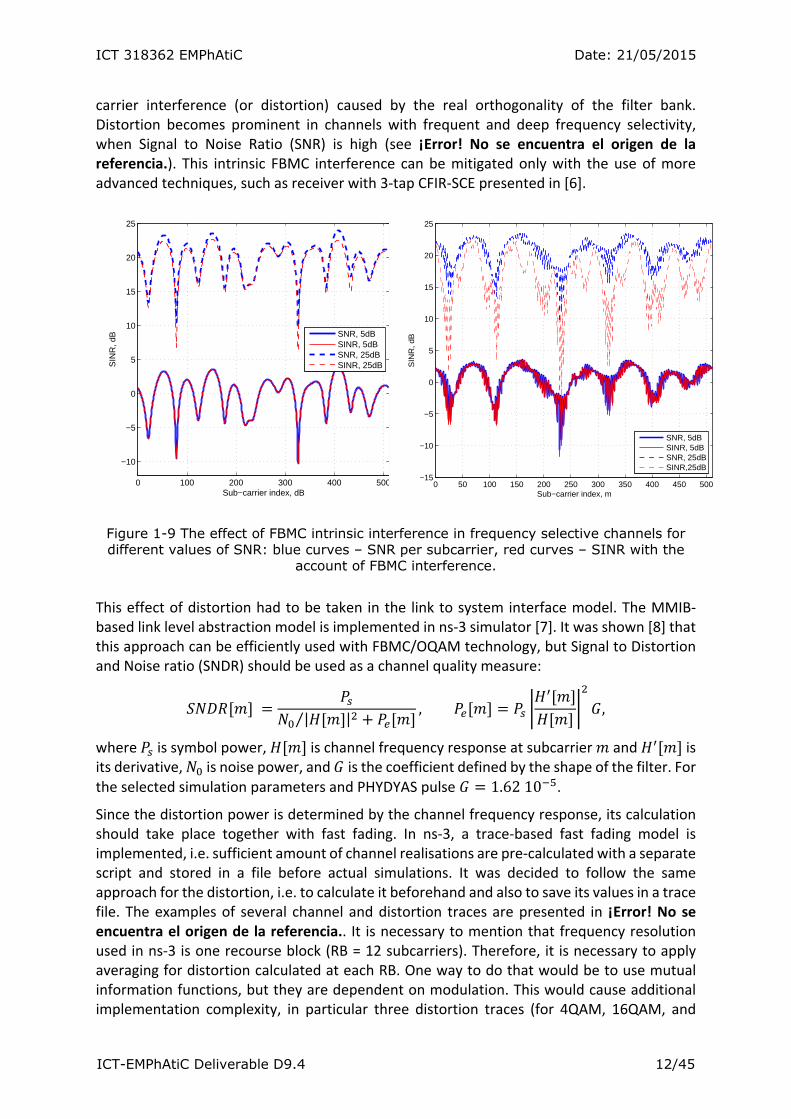
The implementation architecture of the shadowing model in ns‐3 simulator is presented in ¡Error! No se encuentra el origen de la referencia.. Each base station has its own pre‐calculated shadowing map. Shadowing is added as an additional propagation loss model that follows the pathloss calculation. The exact values of shadowing are taken from the map according to the terminal’s coordinates and depending on transmitting base station. ¡Error! No se encuentra el origen de la referencia. demonstrates joint effect of pathloss and shadowing in the studied scenario. The dominance map that shows base station with the strongest Rx power in each geographical can be seen in ¡Error! No se encuentra el origen de la referencia..
Propagation loss model (for example
3GPP)
DL/UL Spectrum Channel
Shadowing propogation loss models
Enb LTE PHY
SetNext ()
DL/UL Spectrum PHY
Enb Net Device
GetUlSpectrumPhy()
GetDlSpectrumPhy()
Shadowing Map
GetDevice()
Aggregation / GetObject ()
GetChannel()
GetDevice()
Helper
GetPropogationLoss()
ICT 318362 EMPhAtiC Date: 21/05/2015
ICT-EMPhAtiC Deliverable D9.4 11/45
Figure 1-7 Propagation map with correlated shadowing.
Figure 1-8 Dominance map with shadowing.
1.2.3 Link to system mapping
The characteristics of FBMC/OQAM technology have been widely discussed in the literature and previous project deliverables. One of such peculiarities is the existence of specific inter‐
ICT 318362 EMPhAtiC Date: 21/05/2015
ICT-EMPhAtiC Deliverable D9.4 12/45
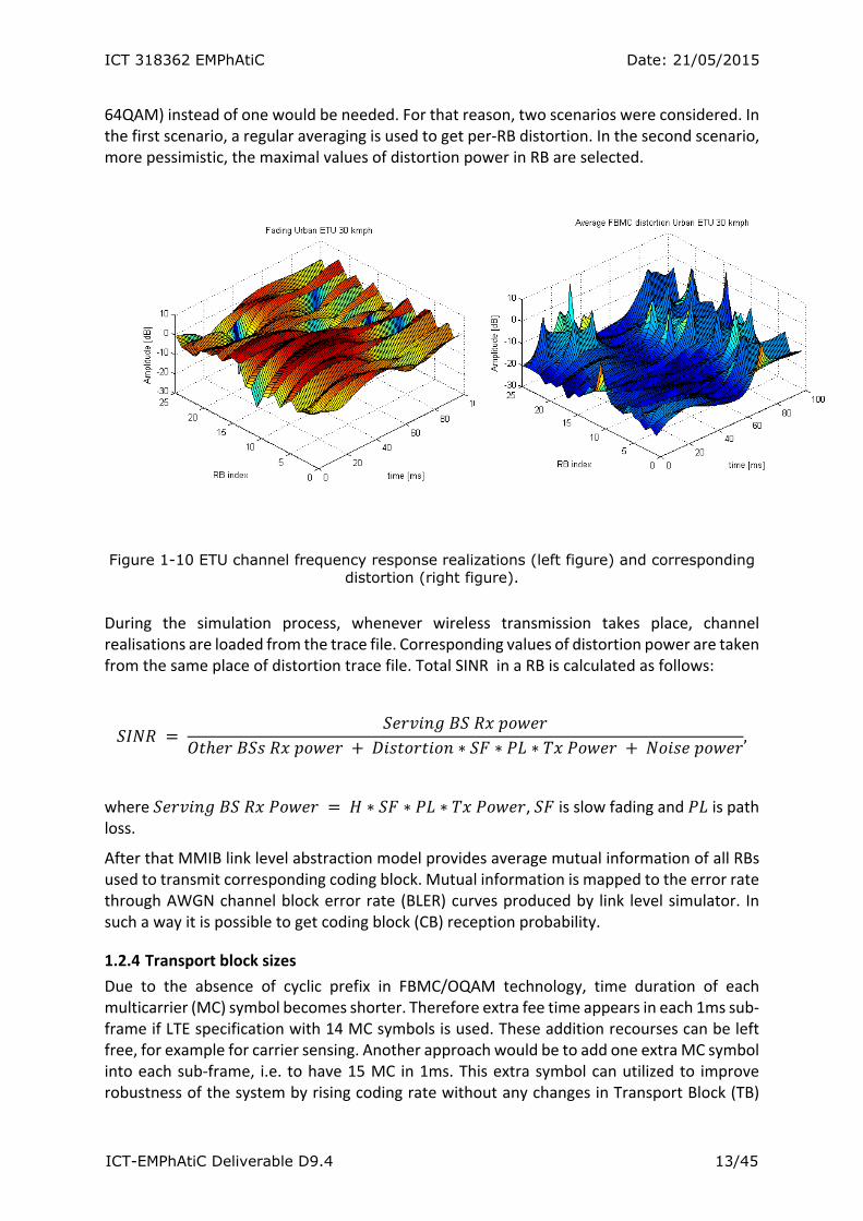
carrier interference (or distortion) caused by the real orthogonality of the filter bank. Distortion becomes prominent in channels with frequent and deep frequency selectivity, when Signal to Noise Ratio (SNR) is high (see ¡Error! No se encuentra el origen de la referencia.). This intrinsic FBMC interference can be mitigated only with the use of more advanced techniques, such as receiver with 3‐tap CFIR‐SCE presented in [6].
Figure 1-9 The effect of FBMC intrinsic interference in frequency selective channels for different values of SNR: blue curves – SNR per subcarrier, red curves – SINR with the
account of FBMC interference.
This effect of distortion had to be taken in the link to system interface model. The MMIB‐based link level abstraction model is implemented in ns‐3 simulator [7]. It was shown [8] that this approach can be efficiently used with FBMC/OQAM technology, but Signal to Distortion and Noise ratio (SNDR) should be used as a channel quality measure:
| |⁄
, ,
where is symbol power, is channel frequency response at subcarrier and is its derivative, is noise power, and is the coefficient defined by the shape of the filter. For the selected simulation parameters and PHYDYAS pulse 1.6210 .
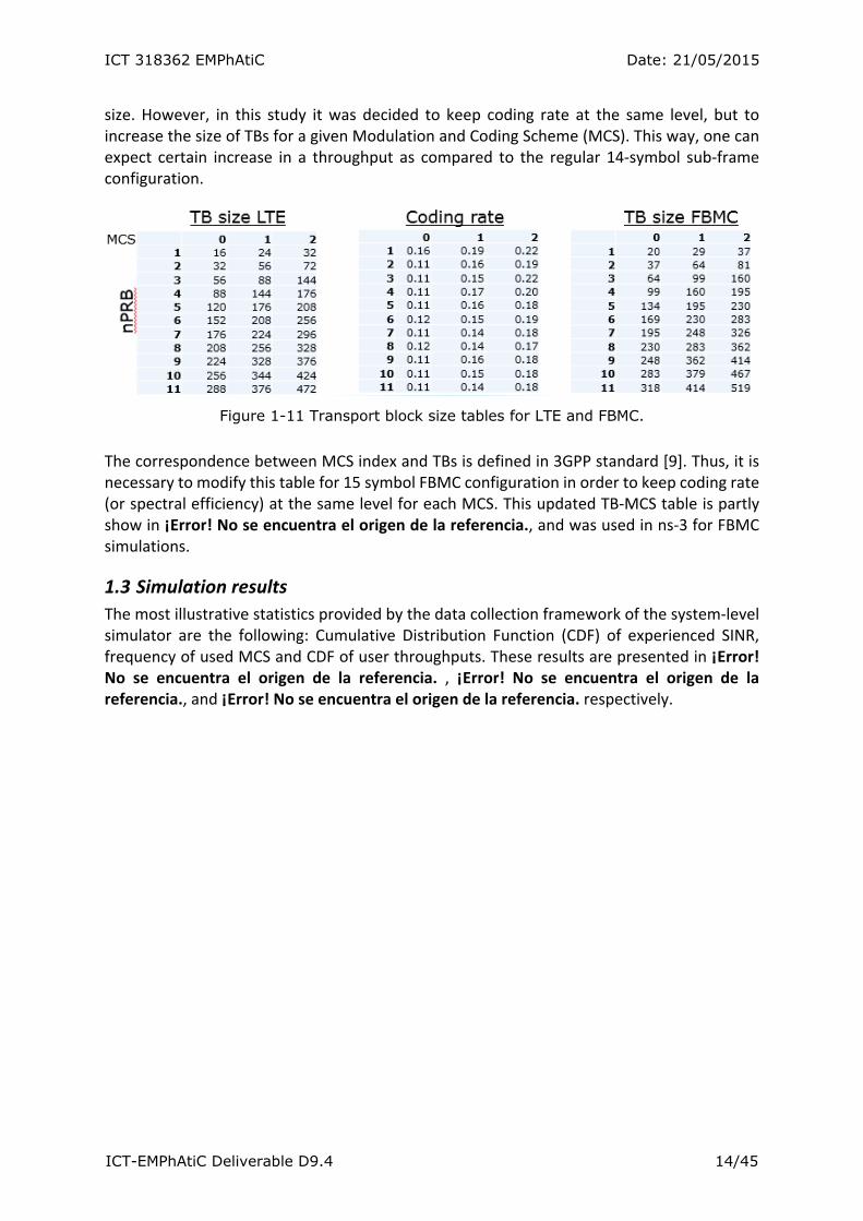
Since the distortion power is determined by the channel frequency response, its calculation should take place together with fast fading. In ns‐3, a trace‐based fast fading model is implemented, i.e. sufficient amount of channel realisations are pre‐calculated with a separate script and stored in a file before actual simulations. It was decided to follow the same approach for the distortion, i.e. to calculate it beforehand and also to save its values in a trace file. The examples of several channel and distortion traces are presented in ¡Error! No se encuentra el origen de la referencia.. It is necessary to mention that frequency resolution used in ns‐3 is one recourse block (RB = 12 subcarriers). Therefore, it is necessary to apply averaging for distortion calculated at each RB. One way to do that would be to use mutual information functions, but they are dependent on modulation. This would cause additional implementation complexity, in particular three distortion traces (for 4QAM, 16QAM, and
0 100 200 300 400 500
−10
−5
0
5
10
15
20
25
Sub−carrier index, dB
SIN
R, d
B
SNR, 5dBSINR, 5dBSNR, 25dBSINR, 25dB
0 50 100 150 200 250 300 350 400 450 500−15
−10
−5
0
5
10
15
20
25
Sub−carrier index, m
SIN
R, d
B
SNR, 5dBSINR, 5dBSNR, 25dBSINR,25dB
ICT 318362 EMPhAtiC Date: 21/05/2015
ICT-EMPhAtiC Deliverable D9.4 13/45
64QAM) instead of one would be needed. For that reason, two scenarios were considered. In the first scenario, a regular averaging is used to get per‐RB distortion. In the second scenario, more pessimistic, the maximal values of distortion power in RB are selected.
Figure 1-10 ETU channel frequency response realizations (left figure) and corresponding distortion (right figure).
During the simulation process, whenever wireless transmission takes place, channel realisations are loaded from the trace file. Corresponding values of distortion power are taken from the same place of distortion trace file. Total SINR in a RB is calculated as follows:
∗ ∗ ∗ ,
where ∗ ∗ ∗ , is slow fading and is path loss.
After that MMIB link level abstraction model provides average mutual information of all RBs used to transmit corresponding coding block. Mutual information is mapped to the error rate through AWGN channel block error rate (BLER) curves produced by link level simulator. In such a way it is possible to get coding block (CB) reception probability.
1.2.4 Transport block sizes
Due to the absence of cyclic prefix in FBMC/OQAM technology, time duration of each multicarrier (MC) symbol becomes shorter. Therefore extra fee time appears in each 1ms sub‐frame if LTE specification with 14 MC symbols is used. These addition recourses can be left free, for example for carrier sensing. Another approach would be to add one extra MC symbol into each sub‐frame, i.e. to have 15 MC in 1ms. This extra symbol can utilized to improve robustness of the system by rising coding rate without any changes in Transport Block (TB)
ICT 318362 EMPhAtiC Date: 21/05/2015
ICT-EMPhAtiC Deliverable D9.4 14/45
size. However, in this study it was decided to keep coding rate at the same level, but to increase the size of TBs for a given Modulation and Coding Scheme (MCS). This way, one can expect certain increase in a throughput as compared to the regular 14‐symbol sub‐frame configuration.
Figure 1-11 Transport block size tables for LTE and FBMC.
The correspondence between MCS index and TBs is defined in 3GPP standard [9]. Thus, it is necessary to modify this table for 15 symbol FBMC configuration in order to keep coding rate (or spectral efficiency) at the same level for each MCS. This updated TB‐MCS table is partly show in ¡Error! No se encuentra el origen de la referencia., and was used in ns‐3 for FBMC simulations.
1.3 Simulation results
The most illustrative statistics provided by the data collection framework of the system‐level simulator are the following: Cumulative Distribution Function (CDF) of experienced SINR, frequency of used MCS and CDF of user throughputs. These results are presented in ¡Error! No se encuentra el origen de la referencia. , ¡Error! No se encuentra el origen de la referencia., and ¡Error! No se encuentra el origen de la referencia. respectively.
ICT 318362 EMPhAtiC Date: 21/05/2015
ICT-EMPhAtiC Deliverable D9.4 15/45
Figure 1-12 SINR CDF in scenarios with different distortion.
Figure 1-13 MCS utilization frequency for LTE and FMBC based PMR systems.
ICT 318362 EMPhAtiC Date: 21/05/2015
ICT-EMPhAtiC Deliverable D9.4 16/45
Figure 1-14 User throughput CDFs in LTE and PMR systems with different equalizers and distortion strength.
As expected, the effect of distortion is mostly visible for higher values of SINR, when noise and interference from other base stations is not very strong. For lower SINRs the influence of distortion is not considerable. This SINR behaviour results in the fact that higher MCS indexes are not used that often in PMR system as in LTE.
Finally, ¡Error! No se encuentra el origen de la referencia. demonstrates the fact that regardless of extra resources in a sub‐frame, throughput of PMR users with simple 1‐tap equalizer is comparable, but slightly lower than in LTE system. Higher throughputs can be achieved only when more advanced 3‐tap equalizer is utilized.
1.4 Demonstration and NEF player
Modern simulation environment is not only simulator itself, but also accompanying infrastructure. It includes tools for code storage and team development, for testing and integration, for running simulation campaigns, for processing and visualization of the results. A simulator‐independent event visualisation tool has been used together with the simulation scenario to demonstrate the network dynamics and characteristics during the runtime. A special library and appropriate function calls were integrated into the ns‐3. The library outputs proprietary network events into a binary file. This explains the naming of the tool ‐ Network Event File (NEF) player.
ICT 318362 EMPhAtiC Date: 21/05/2015
ICT-EMPhAtiC Deliverable D9.4 17/45
Figure 1-15 Simulation infrastructure.
The network event file is complemented by new events during simulation process. Then it is read by the player. NEF Player visualizes the following contents of the file:
Simulation playback (real‐time, slow‐motion, increased speed), stop, rewind, fast‐
forward;
Nodes visualized as changeable and scalable icons;
Node selections, search, movement tracing, parameters / statistics visualization
(numerical, bar graph);
Connections visualization;
Dynamically updatable background images (Propagation data, buildings, roads, walls,
maps, satellite imagery);
Node/connection statistics as time traces (e.g. throughput, RSRP, MCS, etc.);
Node/connection state visualization (e.g. node sleep/idle state);
Node icons, background images, sub‐icons can be embedded into the file.
The interface of the NEF player with the studied scenario is shown in the figure below.
ICT 318362 EMPhAtiC Date: 21/05/2015
ICT-EMPhAtiC Deliverable D9.4 18/45
Figure 1-16 NEF GUI for visualisation of simulations.
Between the benefits of NEF player it is possible to point out the following features: 1. Savings in development and maintenance
a. No need to develop or maintain separate graphical user interfaces (GUI) or
visualization tools for different simulators
2. Easily to integrate
a. Optimized C++ based NEF‐library can be easily integrated with different
simulators.
b. Simulations can be visualized with QT based NEF Player in Windows and Linux
environments
3. Faster results analysis and development cycle
a. Efficient simulation visualization helps to analyse the simulated system /
network performance for R&D and marketing purposes for both technical
and non‐technical audience
4. Demystifying R&D work
a. Visual representation of the results offers a window for non‐technical
personnel to the oftentimes theoretical R&D work
The NEF library is a static library that is integrated into a simulator. The library offers a C/C++ interface to record simulation events that describe what happens in a simulation: time stepping, node creations/deletions, connection creation/deletion and various statistic updates (which can be freely added and updated): continuous statistics such as signal level, throughput, state statistics such as nodes sleep/idle mode or transmission direction (UL/DL) and event‐like statistics such as occurrences of handovers or radio link failures.
ICT 318362 EMPhAtiC Date: 21/05/2015
ICT-EMPhAtiC Deliverable D9.4 19/45
2. Hardware demonstrator The purpose of this document is to provide evaluation results of the EMPhAtiC demonstrator and system level simulator. The main focus is on the FBMC transmitter and receiver, which are based on a fast convolution processing scheme. Implementation metrics of the different target technologies are provided: that is, embedded programmable area‐usage in the case of the real‐time SoC‐based transmitter implementation and processor usage and latencies in the case of the SDR‐based receiver system. Furthermore, experimental performance results are given that allow to characterize the gains of the proposed FBMC scheme when coexisting with current PMR systems.
2.1 Basic description of the hardware‐demonstrator
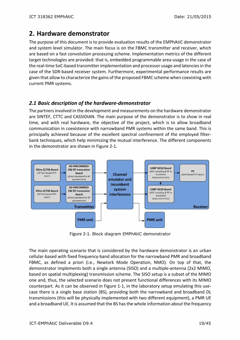
The partners involved in the development and measurements on the hardware demonstrator are SINTEF, CTTC and CASSIDIAN. The main purpose of the demonstrator is to show in real time, and with real hardware, the objective of the project, which is to allow broadband communication in coexistence with narrowband PMR systems within the same band. This is principally achieved because of the excellent spectral confinement of the employed filter‐bank techniques, which help minimizing the mutual interference. The different components in the demonstrator are shown in Figure 2‐1.
Figure 2‐1. Block diagram EMPhAtiC demonstrator
The main operating scenario that is considered by the hardware demonstrator is an urban cellular‐based with fixed frequency‐band allocation for the narrowband PMR and broadband FBMC, as defined a priori (i.e., Newtork Mode Operation, NMO). On top of that, the demonstrator implements both a single antenna (SISO) and a multiple‐antenna (2x2 MIMO, based on spatial multiplexing) transmission scheme. The SISO setup is a subset of the MIMO one and, thus, the selected scenario does not present functional differences with its MIMO counterpart. As it can be observed in Figure 1‐1, in the laboratory setup emulating this use‐case there is a single base station (BS), providing both the narrowband and broadband DL transmissions (this will be physically implemented with two different equipment), a PMR UE and a broadband UE. It is assumed that the BS has the whole information about the frequency
ICT 318362 EMPhAtiC Date: 21/05/2015
ICT-EMPhAtiC Deliverable D9.4 20/45
planning of the two networks. Hence, the operation of the broadband system does not interfere the PMR system (which is considered to be the primary one). The RF frequency used is around 400 MHz. Finally, the demonstrator also implements an LTE CP‐OFDM transmission which serves as a performance‐comparison point (i.e., benchmarking of FBMC versus CP‐OFDM).
2.2 Hardware‐acceleration of algorithms and building blocks
Despite the flexibility that a fully SDR solution offers, the upper‐bound performance limit and the excessive power consumption of a general purpose computer (GPC) might reduce the end‐scenarios that can be targeted. A main issue that has been tackled in EMPhAtiC is the performance bottleneck of GPCs. A popular solution, which has been investigated in the project, is to offload the GPC processor by moving part of the bit‐intensive digital signal processing (DSP) operations to a custom designed co‐processor (i.e., custom design targeting a real‐time FPGA‐based implementation). In this sense, both Bitgear and CTTC have investigated the hardware cost and performance gains of using FPGAs.
From Bitgear, the following problems related to the efficient implementation of FBMC schemes have been considered:
Architecture of the FPGA implementation of both FBMC transmitter and receiver systems based on polyphase filters (D2.1);
Architecture of the FPGA implementation of FBMC based on fast convolution (D2.1);
Transmitter and receiver realization based on fast convolution operating on the same frequency (D2.2 and D9.1);
Hardware acceleration of the synchronization module and CFO estimation (D9.2).
FBMC based on FC FPGA implementation on N200 (Ettus Radio) and integration with RF AD9361.
Regarding CTTC, the real‐time transmitter implemented as part of the EMPhAtiC demonstrator is based on a hardware‐assisted SDR approach, which targets a System‐on‐Chip (SoC) baseband processor. Its digital design details, as well as those related to the selected implementation hardware, have been widely covered on previous deliverables (e.g., D9.1, D9.2).
SoCs enclose in a single chip (multi‐core) embedded processors, high performance purpose‐built logic functions, high‐speed embedded memories and a number of I/O and bus interfaces. Hence, the entire idea of hardware‐assisted SDR can be efficiently replicated in a SoC that features programmable logic area (FPGA) and a powerful enough embedded microprocessor. Likewise, the performance bottlenecks introduced by the utilized SDR communication interfaces could be eliminated and the power‐consumption of SDR solutions is dramatically decreased. Conceptually‐wise, the embedded hardware‐assisted SDR also reaches closer to end‐products and commercial end‐solutions, making it more appealing for a whole new range of applications.
In the current document, the resource utilization of the proposed implementations for the transmitter and receiver systems is studied.
ICT 318362 EMPhAtiC Date: 21/05/2015
ICT-EMPhAtiC Deliverable D9.4 21/45
3. Implementation of the transmitter The transmitter implements both FBMC/OQAM and CP‐OFDM modulations. Additionally, in the two cases, both SISO and 2x2 MIMO transmitting schemes are implemented. The transmitted frame is fully detailed in deliverable D9.3.
3.1 Real‐time SoC‐based implementation of the broadband transmitter systems
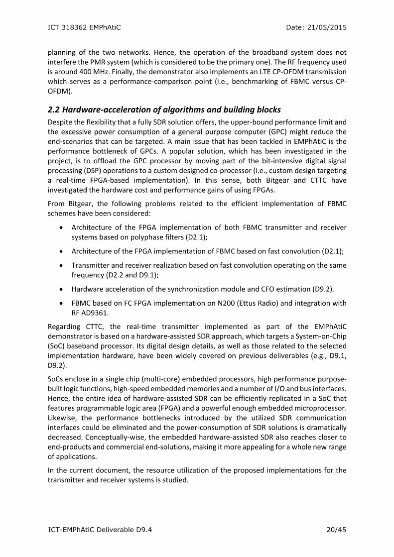
As it is also detailed in D9.3, the real‐time transmitter of the EMPhAtiC demonstrator targets a Xilinx Zynq all‐programmable (AP) SoC. The block diagram of baseband 2x2 MIMO transmitter is shown in Figure 3‐1. The design is implemented on a SoC‐based platform which, besides the SoC‐based baseband processor, also hosts an AD FMCOMMS3 RF dual transceiver chip. The FBMC DSP stages are, thus, fully accelerated and realised on the programmable logic embedded within the Zynq AP SoC (i.e., FPGA).
Figure 3-1. Demonstrator Transmitter Block Diagram
The optimized digital design is based on a modular hierarchical design, which helps identifying and sharing common blocks among the different antenna configurations and between the CP‐OFDM and FBMCFBMC systems. This approach leads to resource usage minimisation, low power consumption, and the possibility to operate at higher clock frequencies. The same architecture is applied to SISO system (except for the precoding scheme). Table 3‐1 provides the attained implementation metrics regarding the broadband transmitter. Besides detailing the costs of implementing all the required antenna and baseband DSP schemes, results of each transmitter configuration as a standalone system are also provided.
Table 3‐1. Implementation metrics (i.e., programmable‐area of the target SoC device) of the
FBMC and LTE CP‐OFDM transmitter systems.
System Slices DSP48E1 RAMB18E1 RAMB36E1

ICT 318362 EMPhAtiC Date: 21/05/2015
ICT-EMPhAtiC Deliverable D9.4 22/45
SISO LTE 6% 2% 1% 1%
MIMO LTE 9% 4% 1% 2%
SISO FBMC 6% 5% 1% 4%
MIMO FBMC 13% 11% 2% 10%
ALL 4 TXs 26% 18% 4% 16%
ICT 318362 EMPhAtiC Date: 21/05/2015
ICT-EMPhAtiC Deliverable D9.4 23/45
4. Implementation of the receiver The demonstrator implements both the SISO and 2x2 MIMO configurations of the proposed FBMC system.
4.1 SDR‐based implementation of the SISO broadband receiver The hardware description used for receiver side is in details described in Deliverable 9.3, the RF front end is Analog Device WBX that covers range from 50 MHz to 2200MHz. The baseband processor is partially placed in the USRP 210 and PC computer. The PC computer is connected with USRP 210 over high speed Ethernet.
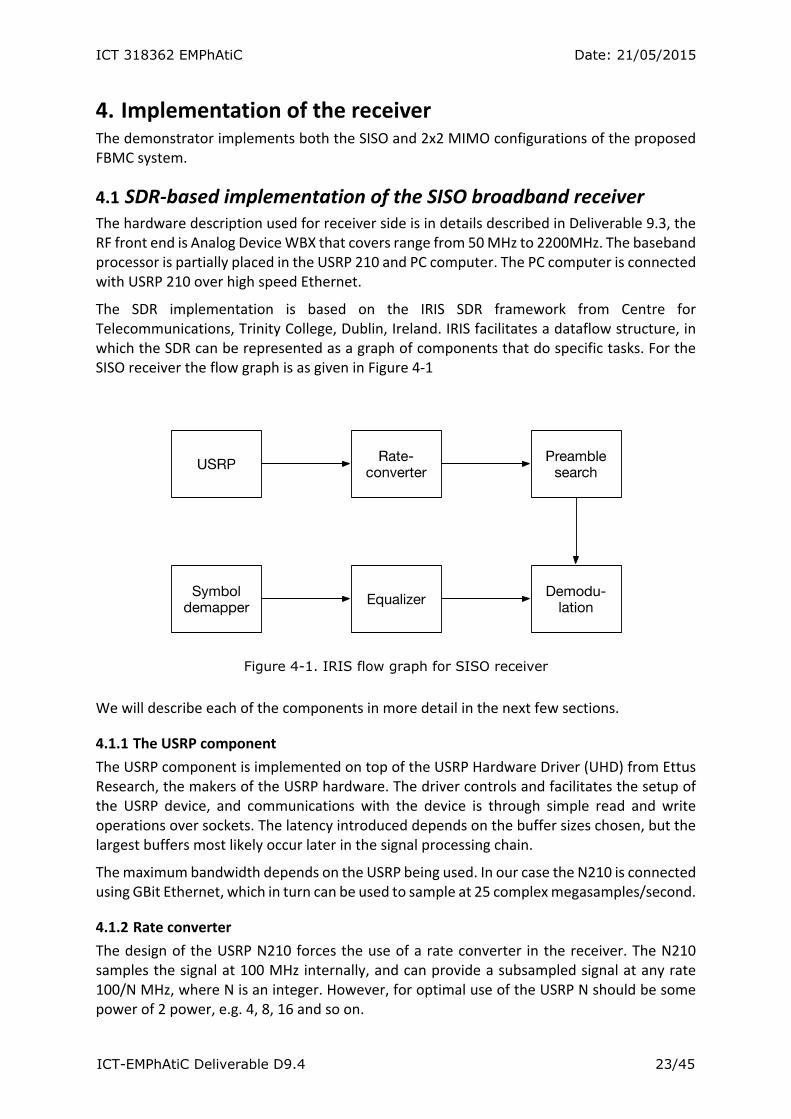
The SDR implementation is based on the IRIS SDR framework from Centre for Telecommunications, Trinity College, Dublin, Ireland. IRIS facilitates a dataflow structure, in which the SDR can be represented as a graph of components that do specific tasks. For the SISO receiver the flow graph is as given in Figure 4‐1
Figure 4-1. IRIS flow graph for SISO receiver
We will describe each of the components in more detail in the next few sections.
4.1.1 The USRP component
The USRP component is implemented on top of the USRP Hardware Driver (UHD) from Ettus Research, the makers of the USRP hardware. The driver controls and facilitates the setup of the USRP device, and communications with the device is through simple read and write operations over sockets. The latency introduced depends on the buffer sizes chosen, but the largest buffers most likely occur later in the signal processing chain.
The maximum bandwidth depends on the USRP being used. In our case the N210 is connected using GBit Ethernet, which in turn can be used to sample at 25 complex megasamples/second.
4.1.2 Rate converter
The design of the USRP N210 forces the use of a rate converter in the receiver. The N210 samples the signal at 100 MHz internally, and can provide a subsampled signal at any rate 100/N MHz, where N is an integer. However, for optimal use of the USRP N should be some power of 2 power, e.g. 4, 8, 16 and so on.
ICT 318362 EMPhAtiC Date: 21/05/2015
ICT-EMPhAtiC Deliverable D9.4 24/45
The EMPhAtiC frame format has been chosen to be similar to LTE, with 15 kHz subchannel bandwidths. The 128 channel band then becomes 1.92 MHz, which does not match 100/N for any N. The closest match is 100/32 = 3.125 MHz, which means that a rate converter with interpolation/decimation ration I/D=384/625 must be used.
The filter becomes very long with thousands of taps, and so an efficient polyphase structure has been utilized and implemented using SSE, the SIMD instruction set for INTEL processors. All in all, about eight additions and multiplications are needed per sample in the current implementation.
4.1.3 Preamble search
The preamble search implements a gliding correlation between the input signal and four distinct preamble sequences. There are only two preamble symbols, but the real and imaginary parts need to be handled separately to implement a coherent detector.
The gliding correlation is implemented using fast convolution FFTs based on the FFTW library from MIT. The computational complexity depends on several choices, but the dominating factor is the relative lengths of the FFT and the overlap factor. If the length of the FFT is N and the overlap factor L, the number of arithmetic operations per sample is in the order of (N log N + C N)/(N‐L). Here the coefficient C includes operations like linear time searches and absolute value computations.
4.1.4 Demodulation
Once the preamble has been found, the demodulation consists of fast convolution computation using a long FFT, followed by matched filtering in the frequency plane and fast convolution IFFT. Again, the computation complexity depends on the ratio between the FTT lengths N, and the overlap L. If the number of channels used is K, the short FFT length is M=2N/K, the number of arithmetic operations per real channel symbol is (N log N + 2N + K M log M)/K. Our implementation uses M=16, K=128, N=1024 and L=384, which in turn gives 20480 arithmetic operations, or 160 arithmetic operation per real channel symbol.
4.1.5 Equalizer
The current implementation is a one tap, zero forcing equalizer. The equalizer is computed using interpolation between pilots in time and frequency. Each data symbol is then equalized using the interpolated pilot.
The complexity of the equalizer is linear in the number of data symbols.
4.1.6 Symbol demapper
The symbol de‐mapper is implemented using a table lookup.
4.1.7 Conclusion
The implementation of the SDR is done using a somewhat high‐level approach, with heavy use of well tested, high quality open source frameworks. This means that an exact analysis of memory and CPU use is impractical. Testing however, shows that a modern PC with an Intel(R) Core(TM) i7‐3720QM CPU @ 2.60GHz uses about 60% of a single core when running the receiver. The memory footprint is in the tens of MB and thus negligible.
ICT 318362 EMPhAtiC Date: 21/05/2015
ICT-EMPhAtiC Deliverable D9.4 25/45
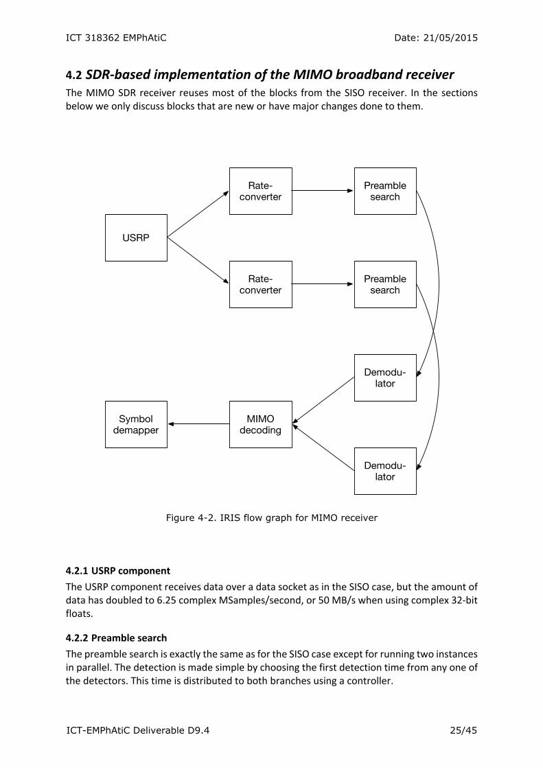
4.2 SDR‐based implementation of the MIMO broadband receiver The MIMO SDR receiver reuses most of the blocks from the SISO receiver. In the sections below we only discuss blocks that are new or have major changes done to them.
Figure 4-2. IRIS flow graph for MIMO receiver
4.2.1 USRP component
The USRP component receives data over a data socket as in the SISO case, but the amount of data has doubled to 6.25 complex MSamples/second, or 50 MB/s when using complex 32‐bit floats.
4.2.2 Preamble search
The preamble search is exactly the same as for the SISO case except for running two instances in parallel. The detection is made simple by choosing the first detection time from any one of the detectors. This time is distributed to both branches using a controller.
ICT 318362 EMPhAtiC Date: 21/05/2015
ICT-EMPhAtiC Deliverable D9.4 26/45
4.2.3 MIMO decoding
The MIMO decoder receives the demodulated signals from both branches. Using the pilots from each branch the channel matrix is computed for every symbol time and channel number using linear interpolation between pilots in time and frequency. Since there are four such parameters for 2x2 MIMO, this operation is four times as complex as for SISO. MIMO decoding involves solving a 2x2 set of linear equations for every symbol, which requires approximately ten arithmetic operations. Compared to the simple one‐tap equalizer used in SISO, this is again approximately four times as complex in the MIMO case.
4.2.4 Conclusion
With the exception of the MIMO decoder, most operations for the 2x2 MIMO case uses twice the resources as for the SISO case. The decoder uses four time the resources. As the SISO receiver used 60% CPU, this means that the computation needs to be distributed across several CPU cores.

ICT 318362 EMPhAtiC Date: 21/05/2015
ICT-EMPhAtiC Deliverable D9.4 27/45
5. Analysis of building blocks in the FBMC system that can be accelerated on hardware
5.1 Transmitter side
For both transmitter schemes, CP‐OFDM and FBMCFBMC, these common blocks are identified:
Data source generator and QAM symbol mapping for CP‐OFDM, additional QAM processing for FBMC;
Data framing, preamble and pilots insertions;
Precoding for 2x2 MIMO case;
CP‐OFDM or FBMC modulation.
The first two operations are related to extensive memory manipulation, so based on the selected hardware platform, these operations should be done using embedded ARM processor. The formatted data are allocated in time and frequency domain in order to prove coexistence with TETRA system.
Formatted data are further processed by MIMO precoder or simply passed to CP‐OFDM or FBMC modulator. The main processing power is basically required by modulator blocks, if we neglect for the moment precoder that can be extremely complicated and demanding.
5.1.1 Complexity comparison: CP‐OFDM and FBMC
Basic FBMC processing block is shown in Figure 5‐1, the complete analysis and implementation is given in D2.1 and D2.2, here is easy to identify large IFFT block which is in common for both processing schemes.
Figure 5-1 Receiver Processing
ICT 318362 EMPhAtiC Date: 21/05/2015
ICT-EMPhAtiC Deliverable D9.4 28/45
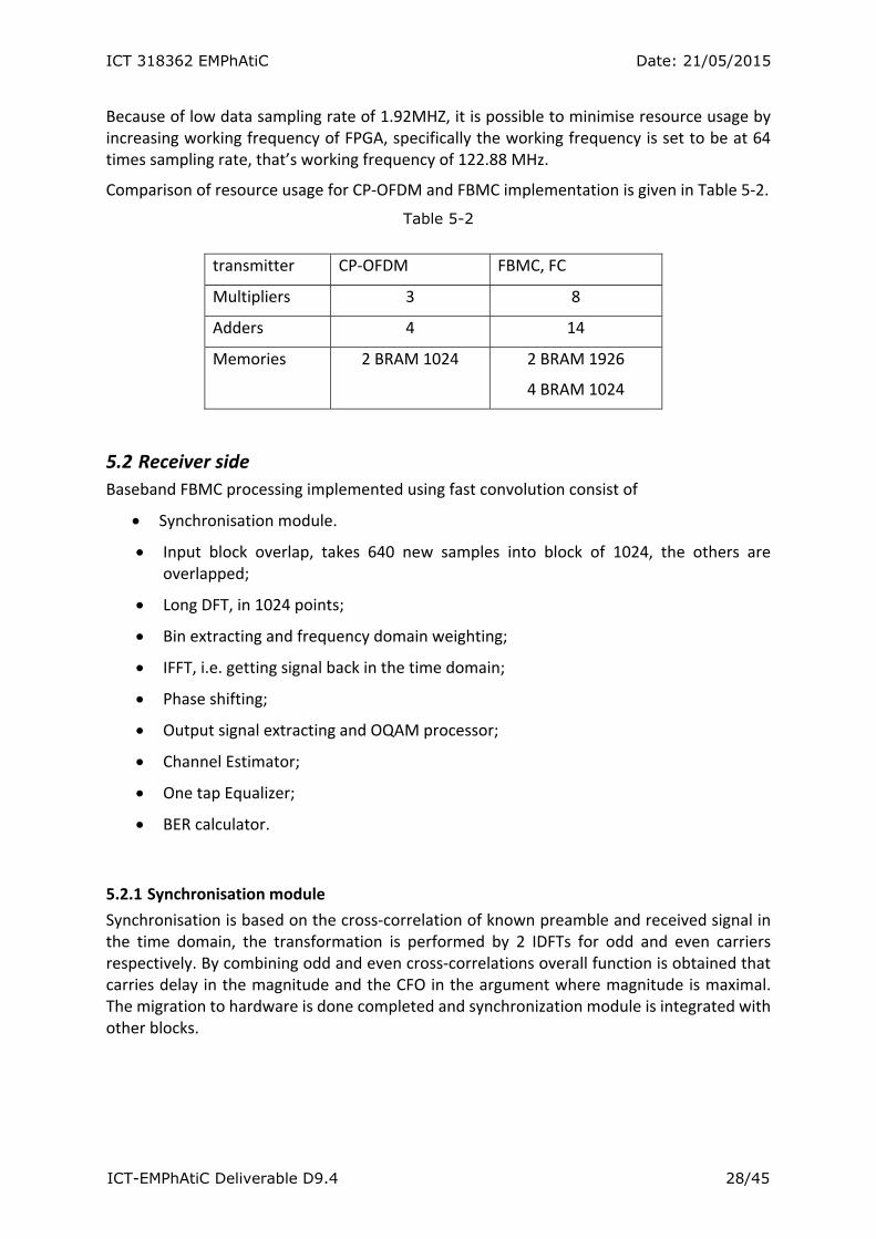
Because of low data sampling rate of 1.92MHZ, it is possible to minimise resource usage by increasing working frequency of FPGA, specifically the working frequency is set to be at 64 times sampling rate, that’s working frequency of 122.88 MHz.
Comparison of resource usage for CP‐OFDM and FBMC implementation is given in Table 5‐2.
Table 5-2
transmitter CP‐OFDM FBMC, FC
Multipliers 3 8
Adders 4 14
Memories 2 BRAM 1024
2 BRAM 1926
4 BRAM 1024
5.2 Receiver side Baseband FBMC processing implemented using fast convolution consist of
Synchronisation module.
Input block overlap, takes 640 new samples into block of 1024, the others are overlapped;
Long DFT, in 1024 points;
Bin extracting and frequency domain weighting;
IFFT, i.e. getting signal back in the time domain;
Phase shifting;
Output signal extracting and OQAM processor;
Channel Estimator;
One tap Equalizer;
BER calculator.
5.2.1 Synchronisation module
Synchronisation is based on the cross‐correlation of known preamble and received signal in the time domain, the transformation is performed by 2 IDFTs for odd and even carriers respectively. By combining odd and even cross‐correlations overall function is obtained that carries delay in the magnitude and the CFO in the argument where magnitude is maximal. The migration to hardware is done completed and synchronization module is integrated with other blocks.

ICT 318362 EMPhAtiC Date: 21/05/2015
ICT-EMPhAtiC Deliverable D9.4 29/45
Table 5-3 Synchronisation Resources
Synchronization Module FBMC
Multipliers 6
Adders 44
Memories 10 BRAM 1024
Magnitude and phase of cross‐correlations is calculated using CORDIC engine; therefore the number of adders is increased comparing to multipliers.
5.2.2 Long overlap
Long overlap performs data blocking, where each block consist of 640 new samples and 384 are overlapped from the previous block.
Table 5-4 Long Overlap
Long Overlap FBMC
Multipliers 0
Adders 0
Memories 1 BRAM 1024
5.2.3 Long DFT
The DFT transforms from time domain to frequency domain blocked signals with desired overlap. The DFT is made of one dragonfly with 3 multipliers, adders and 2 memories for storage and one ROM for coefficients. One dragonfly is sheared and used for all necessary calculations.
Table 5-5 Long DFT
Resources FBMC
Multipliers 3
Adders 4
Memories 3 BRAM 1024
5.2.4 Frequency domain weighting
Weighting is using two multipliers, for real and imaginary part separately. Considering real case weights, Table 5‐6 shows used resources.
ICT 318362 EMPhAtiC Date: 21/05/2015
ICT-EMPhAtiC Deliverable D9.4 30/45
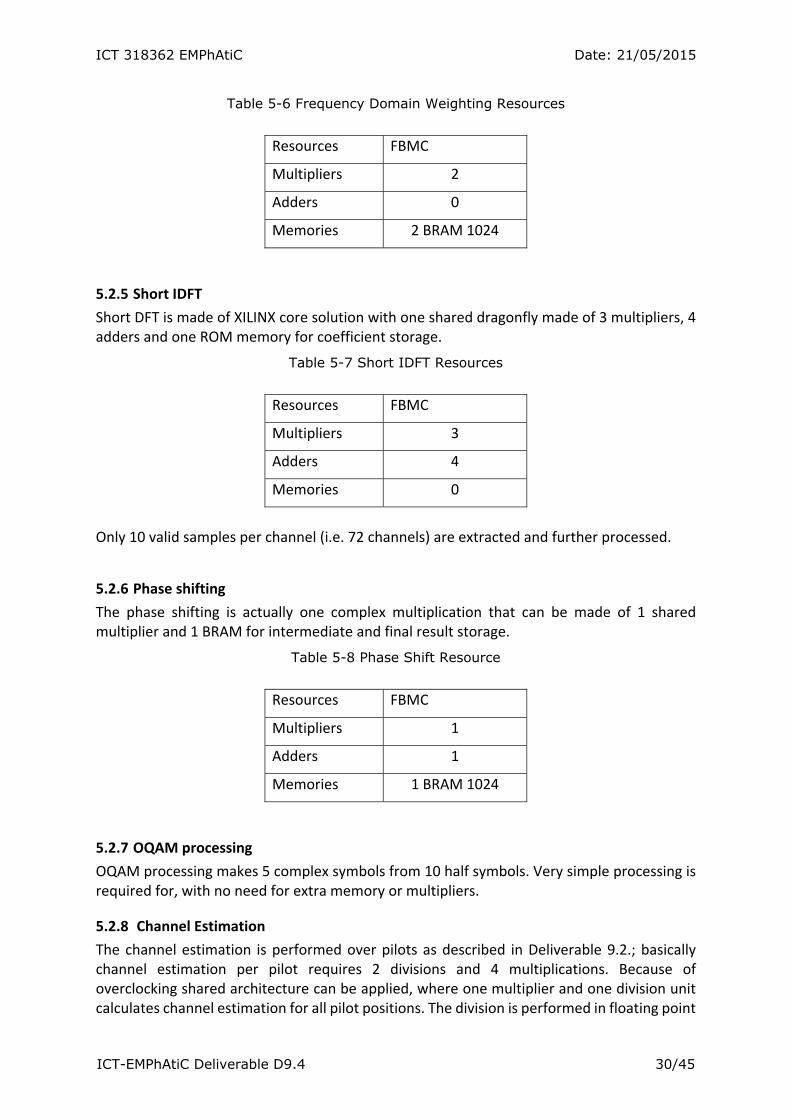
Table 5-6 Frequency Domain Weighting Resources
Resources FBMC
Multipliers 2
Adders 0
Memories 2 BRAM 1024
5.2.5 Short IDFT
Short DFT is made of XILINX core solution with one shared dragonfly made of 3 multipliers, 4 adders and one ROM memory for coefficient storage.
Table 5-7 Short IDFT Resources
Resources FBMC
Multipliers 3
Adders 4
Memories 0
Only 10 valid samples per channel (i.e. 72 channels) are extracted and further processed.
5.2.6 Phase shifting
The phase shifting is actually one complex multiplication that can be made of 1 shared multiplier and 1 BRAM for intermediate and final result storage.
Table 5-8 Phase Shift Resource
Resources FBMC
Multipliers 1
Adders 1
Memories 1 BRAM 1024
5.2.7 OQAM processing
OQAM processing makes 5 complex symbols from 10 half symbols. Very simple processing is required for, with no need for extra memory or multipliers.
5.2.8 Channel Estimation
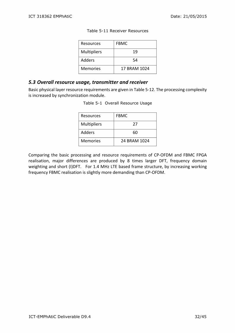
The channel estimation is performed over pilots as described in Deliverable 9.2.; basically channel estimation per pilot requires 2 divisions and 4 multiplications. Because of overclocking shared architecture can be applied, where one multiplier and one division unit calculates channel estimation for all pilot positions. The division is performed in floating point
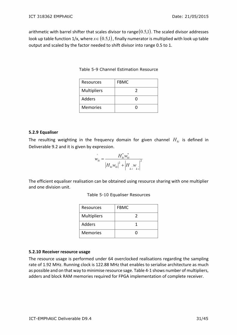
ICT 318362 EMPhAtiC Date: 21/05/2015
ICT-EMPhAtiC Deliverable D9.4 31/45
arithmetic with barrel shifter that scales divisor to range 1,5.0 . The scaled divisor addresses
look up table function 1/x, where 1,5.0x , finally numerator is multiplied with look up table
output and scaled by the factor needed to shift divisor into range 0.5 to 1.
Table 5-9 Channel Estimation Resource
Resources FBMC
Multipliers 2
Adders 0
Memories 0
5.2.9 Equaliser
The resulting weighting in the frequency domain for given channel kiH is defined in
Deliverable 9.2 and it is given by expression.
22
**^
~~ikik
kiki
kikiki
wHwH
wHw
The efficient equaliser realisation can be obtained using resource sharing with one multiplier and one division unit.
Table 5-10 Equaliser Resources
Resources FBMC
Multipliers 2
Adders 1
Memories 0
5.2.10 Receiver resource usage
The resource usage is performed under 64 overclocked realisations regarding the sampling rate of 1.92 MHz. Running clock is 122.88 MHz that enables to serialise architecture as much as possible and on that way to minimise resource sage. Table 4‐1 shows number of multipliers, adders and block RAM memories required for FPGA implementation of complete receiver.
ICT 318362 EMPhAtiC Date: 21/05/2015
ICT-EMPhAtiC Deliverable D9.4 32/45
Table 5-11 Receiver Resources
Resources FBMC
Multipliers 19
Adders 54
Memories 17 BRAM 1024
5.3 Overall resource usage, transmitter and receiver
Basic physical layer resource requirements are given in Table 5‐12. The processing complexity is increased by synchronization module.
Table 5-1 Overall Resource Usage
Resources FBMC
Multipliers 27
Adders 60
Memories 24 BRAM 1024
Comparing the basic processing and resource requirements of CP‐OFDM and FBMC FPGA realisation, major differences are produced by 8 times larger DFT, frequency domain weighting and short (I)DFT. For 1.4 MHz LTE based frame structure, by increasing working frequency FBMC realisation is slightly more demanding than CP‐OFDM.
ICT 318362 EMPhAtiC Date: 21/05/2015
ICT-EMPhAtiC Deliverable D9.4 33/45
6. Experimental coexistence evaluation of the EMPhAtiC demonstrator under mobile channels The EMPhAtiC’s hardware demonstrator aims to provide a physical proof of concept of the gains that the FBMC system in a coexistence scenario with a legacy PMR communication. Towards that end, a number of laboratory tests have been conducted:
1. A baseline cabled setup, composed by two Vector Signal Generators (VSGs) and one Tetrapol terminal, allowed to showcase an ordinary use case, where simultaneous narrowband PMR and opportunistic broadband transmissions where filling up the available spectrum. The superiority of the proposed FBMC signal has been demonstrated against a classical CP‐OFDM one (i.e., 4G LTE) when coexisting with a Tetrapol transmission. An analysis of the performance of the primary system (i.e., Tetrapol) for different transmitted power‐ratios (versus that of the opportunistic broadband transmissions) was included in D9.2.
2. The previous setup was upgraded by replacing the VSGs with the real‐time SoC‐based FBMC transmitter and an additional Tetrapol terminal. Additionally, the SDR‐based FBMC receiver was also included. The resulting demonstrator was shown in the live demonstration that took place at the ETSI Workshop on Reconfigurable Radio Systems (Sophia Antipolis, 3‐4 December 2014). Additionally, brief over‐the‐air experiments were conducted, allowing to experimentally demonstrate the superiority of the proposed waveform. Indeed, under certain conditions where an opportunistic CP‐OFDM transmission was strongly impairing a correct Tetrapol communication, a perfect voice reception was achieved when switching the broadband signal to the proposed FBMC scheme.
3. A real‐time multi‐channel emulator was introduced in the setup in order to thoroughly
evaluate the performance of both Tetrapol and FBMC systems when considering realistic mobile channel conditions.
The final setup of the EMPhAtiC demonstrator is shown in Figure 6‐1.
6.1 Experimental results
The experimental performance assessment included in this section is based on an exhaustive measurement campaign, using the hardware setup as described in the last point above, which covers a comprehensive range of channel models and power‐ratios amongst the transmissions of the primary and secondary systems. In more detail, the demonstrator was configured as follows:
The utilized Tetrapol signals were generated off‐line by uploading a Matlab‐formatted I/Q vector onto a VSG (the utilization of a known data‐sequence allows the posterior calculation of the BER at the receiver side). The VSG was then providing a real‐world RF signal (i.e., they include dedicated high‐performance digital‐to‐analog – DAC – and upconversion circuitry).
Regarding the broadband transmission (for both CP‐OFDM and FBMC schemes), the real‐
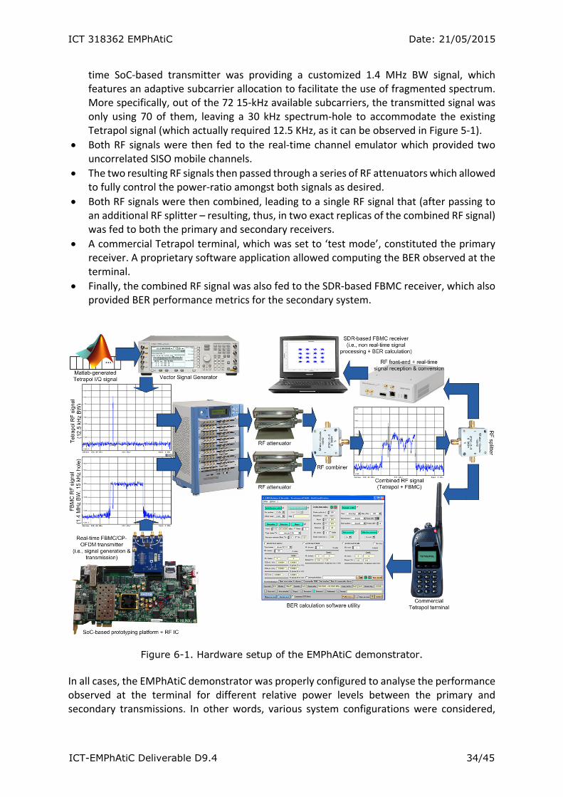
ICT 318362 EMPhAtiC Date: 21/05/2015
ICT-EMPhAtiC Deliverable D9.4 34/45
time SoC‐based transmitter was providing a customized 1.4 MHz BW signal, which features an adaptive subcarrier allocation to facilitate the use of fragmented spectrum. More specifically, out of the 72 15‐kHz available subcarriers, the transmitted signal was only using 70 of them, leaving a 30 kHz spectrum‐hole to accommodate the existing Tetrapol signal (which actually required 12.5 KHz, as it can be observed in Figure 5‐1).
Both RF signals were then fed to the real‐time channel emulator which provided two uncorrelated SISO mobile channels.
The two resulting RF signals then passed through a series of RF attenuators which allowed to fully control the power‐ratio amongst both signals as desired.
Both RF signals were then combined, leading to a single RF signal that (after passing to an additional RF splitter – resulting, thus, in two exact replicas of the combined RF signal) was fed to both the primary and secondary receivers.
A commercial Tetrapol terminal, which was set to ‘test mode’, constituted the primary receiver. A proprietary software application allowed computing the BER observed at the terminal.
Finally, the combined RF signal was also fed to the SDR‐based FBMC receiver, which also provided BER performance metrics for the secondary system.
Figure 6-1. Hardware setup of the EMPhAtiC demonstrator. In all cases, the EMPhAtiC demonstrator was properly configured to analyse the performance observed at the terminal for different relative power levels between the primary and secondary transmissions. In other words, various system configurations were considered,
ICT 318362 EMPhAtiC Date: 21/05/2015
ICT-EMPhAtiC Deliverable D9.4 35/45
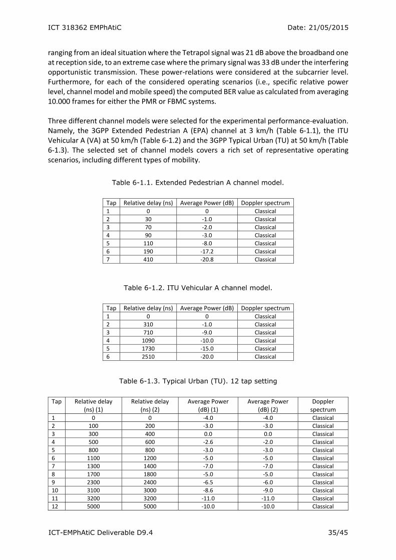
ranging from an ideal situation where the Tetrapol signal was 21 dB above the broadband one at reception side, to an extreme case where the primary signal was 33 dB under the interfering opportunistic transmission. These power‐relations were considered at the subcarrier level. Furthermore, for each of the considered operating scenarios (i.e., specific relative power level, channel model and mobile speed) the computed BER value as calculated from averaging 10.000 frames for either the PMR or FBMC systems. Three different channel models were selected for the experimental performance‐evaluation. Namely, the 3GPP Extended Pedestrian A (EPA) channel at 3 km/h (Table 6‐1.1), the ITU Vehicular A (VA) at 50 km/h (Table 6‐1.2) and the 3GPP Typical Urban (TU) at 50 km/h (Table 6‐1.3). The selected set of channel models covers a rich set of representative operating scenarios, including different types of mobility.
Table 6-1.1. Extended Pedestrian A channel model.
Tap Relative delay (ns) Average Power (dB) Doppler spectrum 1 0 0 Classical
2 30 ‐1.0 Classical
3 70 ‐2.0 Classical
4 90 ‐3.0 Classical
5 110 ‐8.0 Classical
6 190 ‐17.2 Classical
7 410 ‐20.8 Classical
Table 6-1.2. ITU Vehicular A channel model.
Tap Relative delay (ns) Average Power (dB) Doppler spectrum 1 0 0 Classical
2 310 ‐1.0 Classical
3 710 ‐9.0 Classical
4 1090 ‐10.0 Classical
5 1730 ‐15.0 Classical
6 2510 ‐20.0 Classical
Table 6-1.3. Typical Urban (TU). 12 tap setting
Tap Relative delay
(ns) (1) Relative delay
(ns) (2) Average Power
(dB) (1) Average Power
(dB) (2) Doppler spectrum
1 0 0 ‐4.0 ‐4.0 Classical
2 100 200 ‐3.0 ‐3.0 Classical
3 300 400 0.0 0.0 Classical
4 500 600 ‐2.6 ‐2.0 Classical
5 800 800 ‐3.0 ‐3.0 Classical
6 1100 1200 ‐5.0 ‐5.0 Classical
7 1300 1400 ‐7.0 ‐7.0 Classical
8 1700 1800 ‐5.0 ‐5.0 Classical
9 2300 2400 ‐6.5 ‐6.0 Classical
10 3100 3000 ‐8.6 ‐9.0 Classical
11 3200 3200 ‐11.0 ‐11.0 Classical
12 5000 5000 ‐10.0 ‐10.0 Classical

ICT 318362 EMPhAtiC Date: 21/05/2015
ICT-EMPhAtiC Deliverable D9.4 36/45
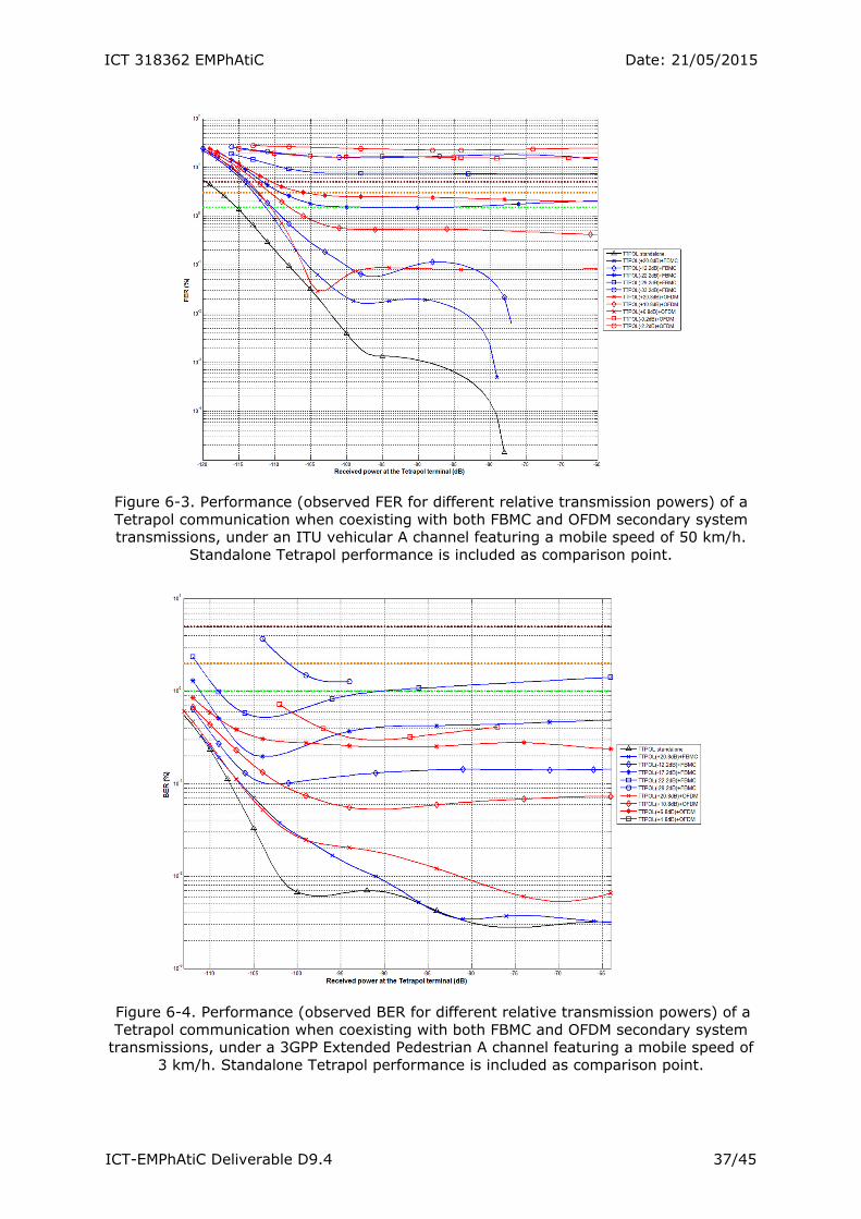
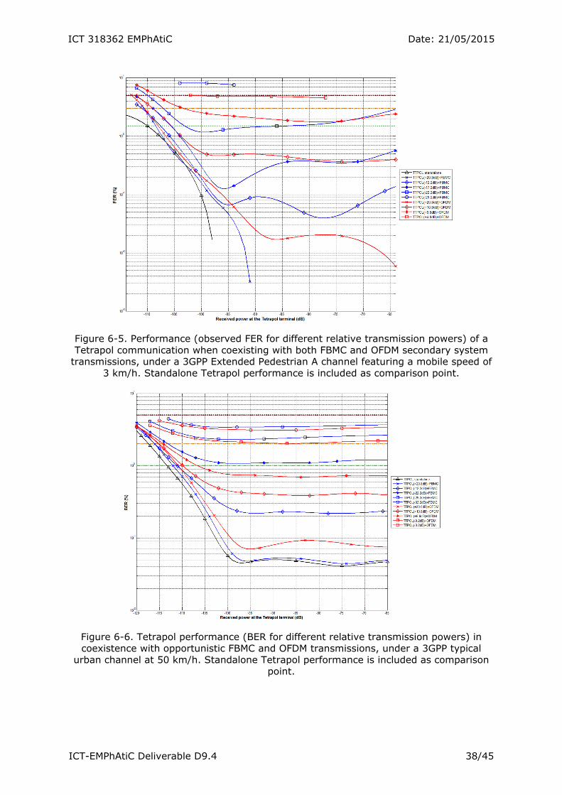
Figure 6‐2 and Figure 6‐3 illustrate the performance observed at the Tetrapol terminal under the ITU VA channel model, featuring a mobile speed of 50 km/h, when coexisting with both broadband FBMC and CP‐OFDM transmissions, as well as a standalone transmission. Performance is measured in terms of bit error rate (BER) and frame error rate (FER) respectively. Similarly, Figures 6‐4 and 6‐5 show similar performance measures under a 3GPP EPA channel model, with a mobile speed of 3 km/h, whereas Figures 6‐6 and 6‐7 analyse the performance under a 3GPP TU channel model, with a mobile speed of 50 km/h. The extensive measurement campaign proves that the demonstrator has successfully achieved its proof‐of‐concept goals. Furthermore, a wide performance comparison has been drawn, which allows to quantize the gains brought by the use of FBMC systems in the considered scenario. In all the cases presented by the figures below, the FBMC system provides a gain of roughly 30dB as compared to the CP‐OFDM scheme, in terms of performance observed at the Tetrapol terminal, as well as from its sensitivity to baseband interferences. Moreover, the use‐case deployed in the demonstrator considers the most stringent and severe operating conditions (i.e., minimal frequency guard‐band between the two coexisting transmissions). Therefore, higher gains could be expected on a less harmful situation, at the cost of a less efficient spectrum reuse (i.e., wider holes in the broadband signal).
Figure 6-2. Performance (observed BER for different relative transmission powers) of a Tetrapol communication when coexisting with both FBMC and OFDM secondary system transmissions, under an ITU vehicular A channel featuring a mobile speed of 50 km/h.
Standalone Tetrapol performance is included as comparison point.
ICT 318362 EMPhAtiC Date: 21/05/2015
ICT-EMPhAtiC Deliverable D9.4 37/45
Figure 6-3. Performance (observed FER for different relative transmission powers) of a Tetrapol communication when coexisting with both FBMC and OFDM secondary system transmissions, under an ITU vehicular A channel featuring a mobile speed of 50 km/h.
Standalone Tetrapol performance is included as comparison point.
Figure 6-4. Performance (observed BER for different relative transmission powers) of a Tetrapol communication when coexisting with both FBMC and OFDM secondary system
transmissions, under a 3GPP Extended Pedestrian A channel featuring a mobile speed of 3 km/h. Standalone Tetrapol performance is included as comparison point.
ICT 318362 EMPhAtiC Date: 21/05/2015
ICT-EMPhAtiC Deliverable D9.4 38/45
Figure 6-5. Performance (observed FER for different relative transmission powers) of a Tetrapol communication when coexisting with both FBMC and OFDM secondary system
transmissions, under a 3GPP Extended Pedestrian A channel featuring a mobile speed of 3 km/h. Standalone Tetrapol performance is included as comparison point.
Figure 6-6. Tetrapol performance (BER for different relative transmission powers) in coexistence with opportunistic FBMC and OFDM transmissions, under a 3GPP typical
urban channel at 50 km/h. Standalone Tetrapol performance is included as comparison point.
ICT 318362 EMPhAtiC Date: 21/05/2015
ICT-EMPhAtiC Deliverable D9.4 39/45
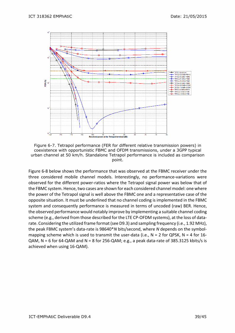
Figure 6-7. Tetrapol performance (FER for different relative transmission powers) in coexistence with opportunistic FBMC and OFDM transmissions, under a 3GPP typical
urban channel at 50 km/h. Standalone Tetrapol performance is included as comparison point.
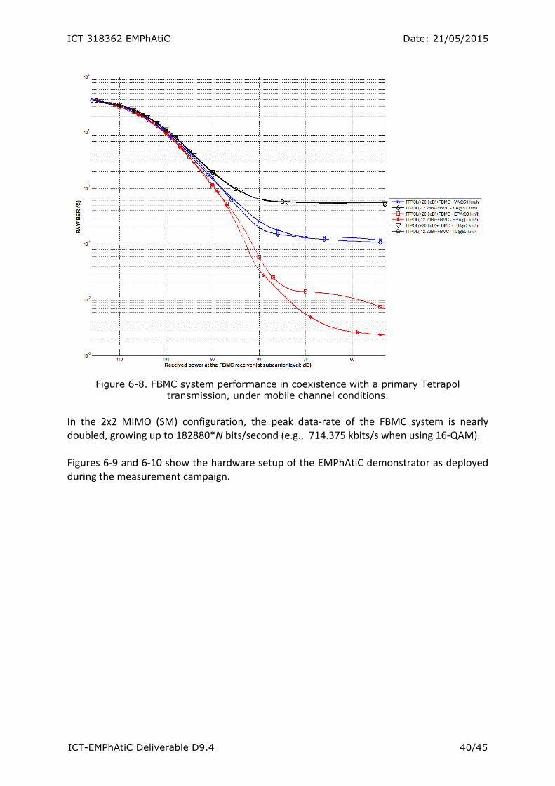
Figure 6‐8 below shows the performance that was observed at the FBMC receiver under the three considered mobile channel models. Interestingly, no performance‐variations were observed for the different power‐ratios where the Tetrapol signal power was below that of the FBMC system. Hence, two cases are shown for each considered channel model: one where the power of the Tetrapol signal is well above the FBMC one and a representative case of the opposite situation. It must be underlined that no channel coding is implemented in the FBMC system and consequently performance is measured in terms of uncoded (raw) BER. Hence, the observed performance would notably improve by implementing a suitable channel coding scheme (e.g., derived from those described for the LTE CP‐OFDM systems), at the loss of data‐rate. Considering the utilized frame format (see D9.3) and sampling frequency (i.e., 1.92 MHz), the peak FBMC system’s data‐rate is 98640*N bits/second, where N depends on the symbol‐mapping scheme which is used to transmit the user‐data (i.e., N = 2 for QPSK, N = 4 for 16‐QAM, N = 6 for 64‐QAM and N = 8 for 256‐QAM; e.g., a peak data‐rate of 385.3125 kbits/s is achieved when using 16‐QAM).
ICT 318362 EMPhAtiC Date: 21/05/2015
ICT-EMPhAtiC Deliverable D9.4 40/45
Figure 6-8. FBMC system performance in coexistence with a primary Tetrapol
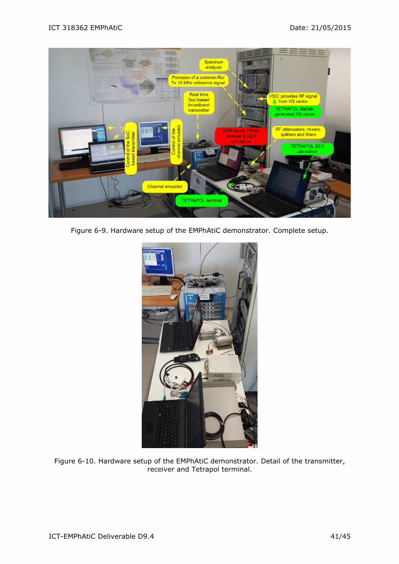
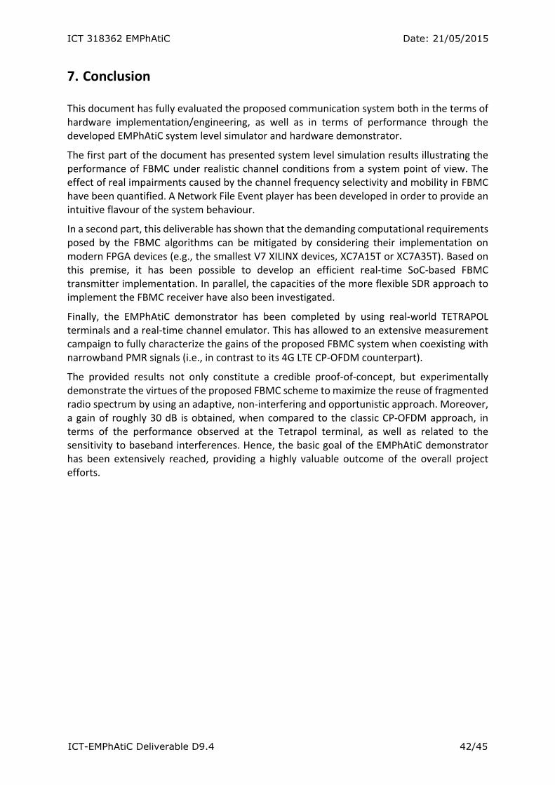
transmission, under mobile channel conditions. In the 2x2 MIMO (SM) configuration, the peak data‐rate of the FBMC system is nearly doubled, growing up to 182880*N bits/second (e.g., 714.375 kbits/s when using 16‐QAM). Figures 6‐9 and 6‐10 show the hardware setup of the EMPhAtiC demonstrator as deployed during the measurement campaign.
ICT 318362 EMPhAtiC Date: 21/05/2015
ICT-EMPhAtiC Deliverable D9.4 41/45
Figure 6-9. Hardware setup of the EMPhAtiC demonstrator. Complete setup.
Figure 6-10. Hardware setup of the EMPhAtiC demonstrator. Detail of the transmitter, receiver and Tetrapol terminal.
ICT 318362 EMPhAtiC Date: 21/05/2015
ICT-EMPhAtiC Deliverable D9.4 42/45
7. Conclusion This document has fully evaluated the proposed communication system both in the terms of hardware implementation/engineering, as well as in terms of performance through the developed EMPhAtiC system level simulator and hardware demonstrator.
The first part of the document has presented system level simulation results illustrating the performance of FBMC under realistic channel conditions from a system point of view. The effect of real impairments caused by the channel frequency selectivity and mobility in FBMC have been quantified. A Network File Event player has been developed in order to provide an intuitive flavour of the system behaviour.
In a second part, this deliverable has shown that the demanding computational requirements posed by the FBMC algorithms can be mitigated by considering their implementation on modern FPGA devices (e.g., the smallest V7 XILINX devices, XC7A15T or XC7A35T). Based on this premise, it has been possible to develop an efficient real‐time SoC‐based FBMC transmitter implementation. In parallel, the capacities of the more flexible SDR approach to implement the FBMC receiver have also been investigated.
Finally, the EMPhAtiC demonstrator has been completed by using real‐world TETRAPOL terminals and a real‐time channel emulator. This has allowed to an extensive measurement campaign to fully characterize the gains of the proposed FBMC system when coexisting with narrowband PMR signals (i.e., in contrast to its 4G LTE CP‐OFDM counterpart).
The provided results not only constitute a credible proof‐of‐concept, but experimentally demonstrate the virtues of the proposed FBMC scheme to maximize the reuse of fragmented radio spectrum by using an adaptive, non‐interfering and opportunistic approach. Moreover, a gain of roughly 30 dB is obtained, when compared to the classic CP‐OFDM approach, in terms of the performance observed at the Tetrapol terminal, as well as related to the sensitivity to baseband interferences. Hence, the basic goal of the EMPhAtiC demonstrator has been extensively reached, providing a highly valuable outcome of the overall project efforts.

ICT 318362 EMPhAtiC Date: 21/05/2015
ICT-EMPhAtiC Deliverable D9.4 43/45
Glossary and definitions
AWGN Additive White Gaussian Noise
BER Bit Error Ratio
BLER Block Error Ratio
B‐PMR Broadband PMR
BPSK Binary Phase Shift Keying
BW Bandwidth
CDF Cumulative Distribution Function
CP Cyclic Prefix
CP‐OFDM Orthogonal Frequency Division Multiplex with Cyclic Prefix
CQI Channel Quality Indicator
DC Direct Current
ESM Effective SINR Mapping
ETSI European Telecommunications Standards Institute
EVA Extended Vehicular A
EVM Error Vector Magnitude
FER Frame Error Rate
FPGA Field Programmable Gate Array
FB‐MC Filter Bank Multi‐Carrier
FBMC/OQAM Filter Bank Multi Carrier with Offset QAM subcarrier modulation
FPGA Field Programmable Array
FC Fast Convolution
FC‐FB Fast Convolution Filter Bank
FDMA Frequency Division Multiple Access
GPC General Purpose Computer
ICI Inter‐Carrier Interference
(I)DFT (Inverse) Discrete Fourier Transform
(I)FFT (Inverse) Fast Fourier Transform
I/Q In‐phase/Quadrature (data signal components)
LTE Long Term Evolution
MCS Modulation and Coding Scheme
MMIB Mean Mutual Information per coded Bit
MSE Mean‐Squared Error
NEF Network Event File
OFDM Orthogonal Frequency Division Multiplexing
OFDMA Orthogonal Frequency Division Multiple Access
QAM Quadrature Amplitude Modulation
OQAM Offset Quadrature Amplitude Modulation
PAM Pulse Amplitude Modulation
PDF Probability Distribution Function
PHY Physical layer
PMR Professional Mobile Radio
PPDR Public Protection and Disaster Relief
PSD Power Spectral Density
ICT 318362 EMPhAtiC Date: 21/05/2015
ICT-EMPhAtiC Deliverable D9.4 44/45
PSK Phase‐Shift Keying
QPSK Quadrature Phase‐Shift Keying
RAM Random Access Memory
SDR Software Defined RAdio
SoC System on Chip
SINR Signal to Interference plus Noise Ratio
SNDR Signal to Noise plus Distortion Ratio
SNR Signal to Noise Ratio
TB Transport Block
TEDS TETRA Enhanced Data Services
TETRA Terrestrial Trunked Radio
USRP Universal Software Radio Peripheral
UHD USRP hardware driver
VHDL VHSIC Hardware Description Language
VHSIC Very High Speed Integrated Circuits
VSG Vector Signal Generator
ICT 318362 EMPhAtiC Date: 21/05/2015
ICT-EMPhAtiC Deliverable D9.4 45/45
References
[1] EMPhAtiC D9.1, “Definition and Specification of Hardware Demonstrator and Software
Simulator”, 2014. [2] Network Simulator version 3 (ns‐3), https://www.nsnam.org [3] LTE‐EPC Network simulAtor (LENA), http://networks.cttc.es/mobile‐networks/software‐
tools/lena/, https://www.nsnam.org/docs/models/html/lte.html [4] SEAMCAT implementation of Extended Hata and Extended Hata‐SDR models,
http://tractool.seamcat.org/raw‐attachment/wiki/Manual/PropagationModels/ExtendedHata/Hata‐and‐Hata‐SRD‐implementation_v3.pdf
[5] Claussen, Holger. "Efficient modelling of channel maps with correlated shadow fading in mobile radio systems." Personal, Indoor and Mobile Radio Communications, 2005. PIMRC 2005. IEEE 16th International Symposium on. Vol. 1. IEEE, 2005.
[6] Ihalainen, Tero, et al. "Channel equalization in filter bank based multicarrier modulation for wireless communications." EURASIP Journal on Applied Signal Processing 2007.1 (2007): 140‐140.
[7] Mezzavilla, Marco, et al. "A lightweight and accurate link abstraction model for system‐level simulation of LTE networks in ns‐3." Proceedings of the ACM International Conference on Modeling, Analysis and Simulation of Wireless and Mobile Systems (MSWiM). 2012.
[8] Dmitry Petrov, Alexandra Oborina, Lorenza Giupponi and Tobias Hidalgo Stitz, “Link performance model for filter bank based multicarrier systems”, EURASIP Journal on Advances in Signal Processing 2014, 2014:169.
[9] 3GPP TS 36.213. “LTE; Evolved Universal Terrestrial Radio Access (E‐UTRA); Physical layer procedures”, 2009.