enhanced smart report templates and border …spi-ltuf.org/20141112/5 enhanced report template...
TRANSCRIPT

FLUOR
SmartPlant ©
Implementation Team
Enhanced Smart Report
Templates and Border
Customization
Copyright © 2005 Fluor Corporation all rights reserved Copyright © 2009 Fluor Corporation – all rights reserved

AV\filename.ppt 2
Enhanced Report Templates
Templates are files that determine the sheet size, orientation, and border for Enhanced Reports. These files have an .sma extension.
The Enhanced Report Utility comes
shipped with several standard templates.
Template File Description
A3tall.sma A3 portrait
A3wide.sma A3 landscape
A4tall.sma A4 portrait
A4wide.sma A4 landscape
Atall.sma 11 in x 8.5 in portrait (Letter)
Awide.sma 11 in x 8.5 in landscape (Letter)
Btall.sma 11 in x 17 in portrait
Bwide.sma 11 in x 17 in landscape
And of course, Normal.sma

AV\filename.ppt 3
Customizing ESR Templates
Before starting, locate and make a backup copy of the ESR drawing template files Normal.sma. They can be found in:
<SPI root directory>/RAD/Template/Types/Loop, Fieldbus Loop, Strip, etc.
Note: There are multiple folders with “Normal.sma” files. You will need to copy each of the files that you plan to use. You do not have to modify all Normal.sma files, only those you will use for your project. Do not copy Normal.sma files between folders

AV\filename.ppt 4
Customizing ESR Templates
Commonly Used “Normal.sma” (Template) file directories;
Loop – The Normal.sma file in this folder is used as the background template for Conventional I/O Loops. This is NOT used for “Bus” Loops.
Strip – This folder has three Normal.sma files located in it, two of which are located under sub folders Style 1 and Style 2. The Normal.sma files under these folders are used as the background templates to generate Panel-Strip reports with adjacent connections. The Style 1 and Style 2 folders give the user additional options for templates, do not confuse these with Smart Reports, style 1 and style 2 (Panel-Strip w/o adjacent Connections)
Fieldbus – The Normal.sma file located in this folder is used as the background template for Segment Reports.
FieldbusLoop - The Normal.sma file located in this folder is used as the background template for Loops that have Fieldbus I/O devices in the Loop. This is the Loop template that SPI will pull even if your Loop has conventional and Fieldbus devices assigned to the same Loop number. You can copy the Normal.sma file for Loops into
this folder.
AV\filename.ppt 5
Customizing ESR Templates
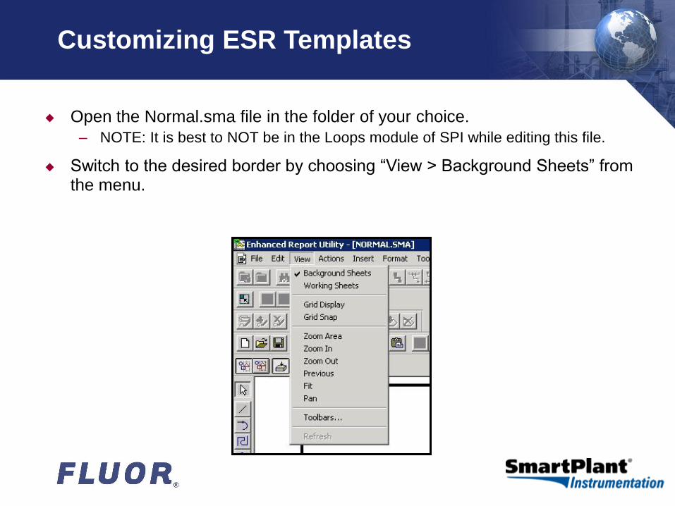
Open the Normal.sma file in the folder of your choice.
– NOTE: It is best to NOT be in the Loops module of SPI while editing this file.
Switch to the desired border by choosing “View > Background Sheets” from the menu.

AV\filename.ppt 6
Customizing ESR Templates
There is a separate border graphic background Template for various sheet sizes
Pick the size on which you wish to work by selecting the tab along the bottom edge of the work area
– NOTE: If you wish to anchor a report to a paper size, remove all the other sheet size tabs from the normal.sma after you have modified it
AV\filename.ppt 7
Creating new ESR Borders
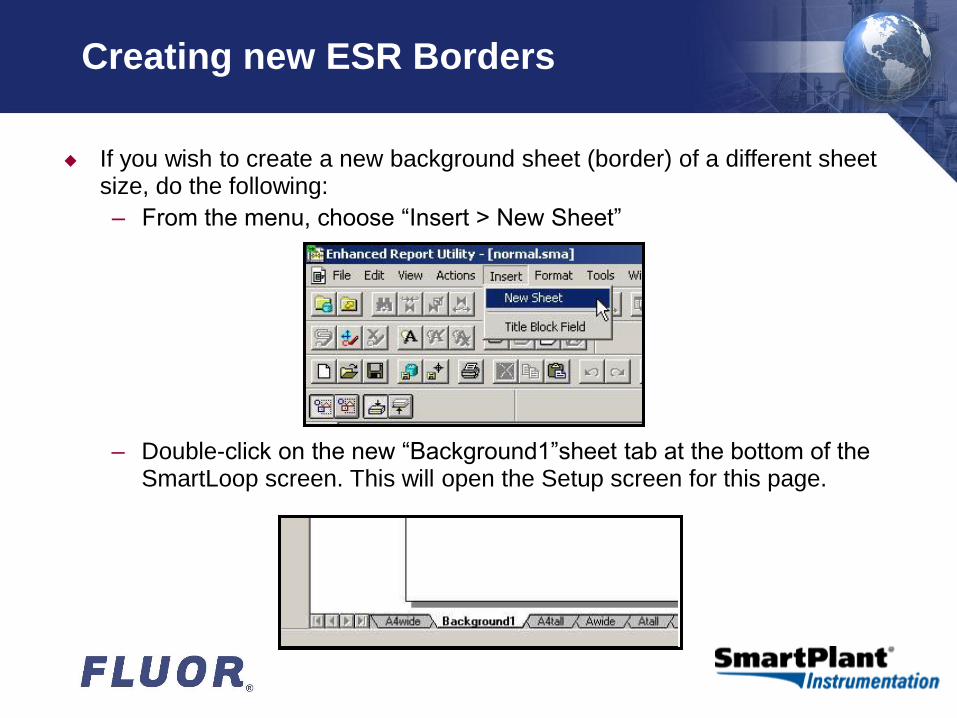
If you wish to create a new background sheet (border) of a different sheet size, do the following:
– From the menu, choose “Insert > New Sheet”
– Double-click on the new “Background1”sheet tab at the bottom of the SmartLoop screen. This will open the Setup screen for this page.
AV\filename.ppt 8
Creating new ESR Borders
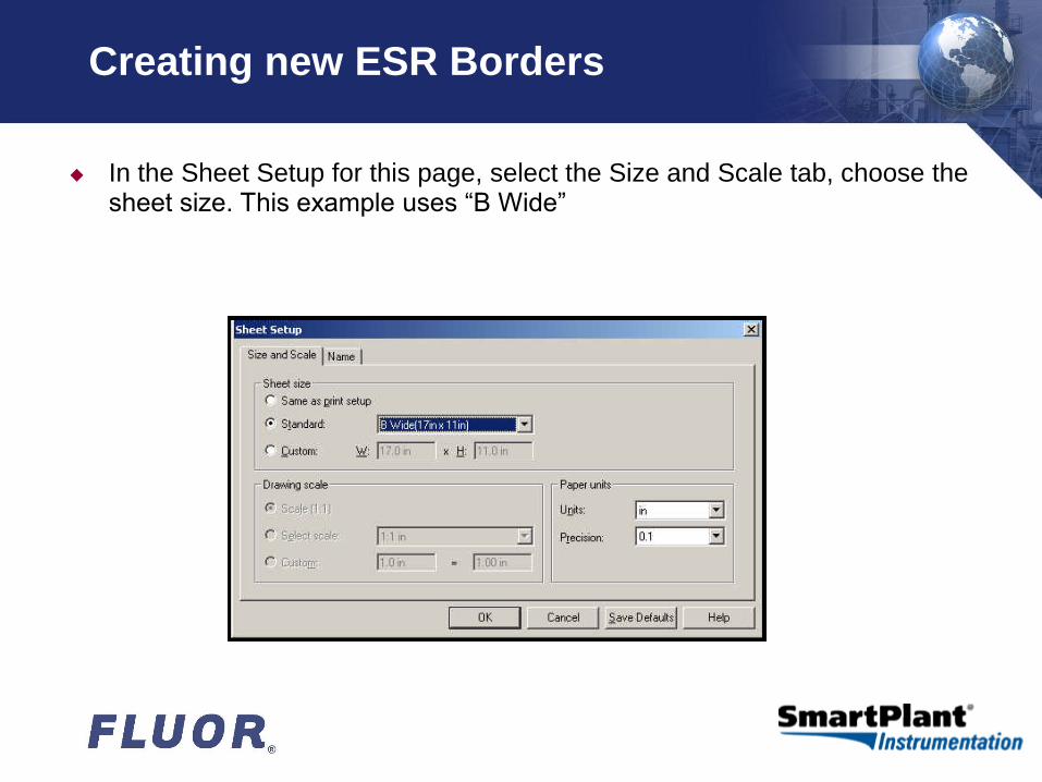
In the Sheet Setup for this page, select the Size and Scale tab, choose the sheet size. This example uses “B Wide”
AV\filename.ppt 9
Creating new ESR Borders
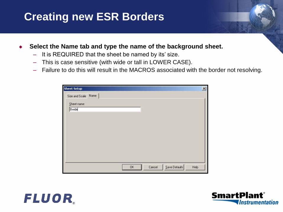
Select the Name tab and type the name of the background sheet.
– It is REQUIRED that the sheet be named by its’ size.
– This is case sensitive (with wide or tall in LOWER CASE).
– Failure to do this will result in the MACROS associated with the border not resolving.
AV\filename.ppt 10
Creating new ESR Borders
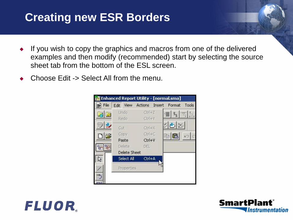
If you wish to copy the graphics and macros from one of the delivered examples and then modify (recommended) start by selecting the source sheet tab from the bottom of the ESL screen.
Choose Edit -> Select All from the menu.

AV\filename.ppt 11
Creating new ESR Borders
All the border graphics should redraw in the ‘select’ color Now hit Ctrl+C
– (or choose Edit -> Copy from the menu).
Switch to your new custom page and paste the copied graphics with Ctrl+V
– (or choose Edit -> Paste from the menu).
AV\filename.ppt 12
Creating new ESR Borders
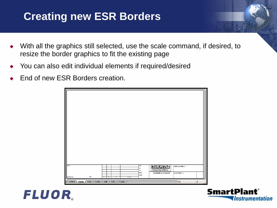
With all the graphics still selected, use the scale command, if desired, to resize the border graphics to fit the existing page
You can also edit individual elements if required/desired
End of new ESR Borders creation.
AV\filename.ppt 13
Modifying ESR Border Logos
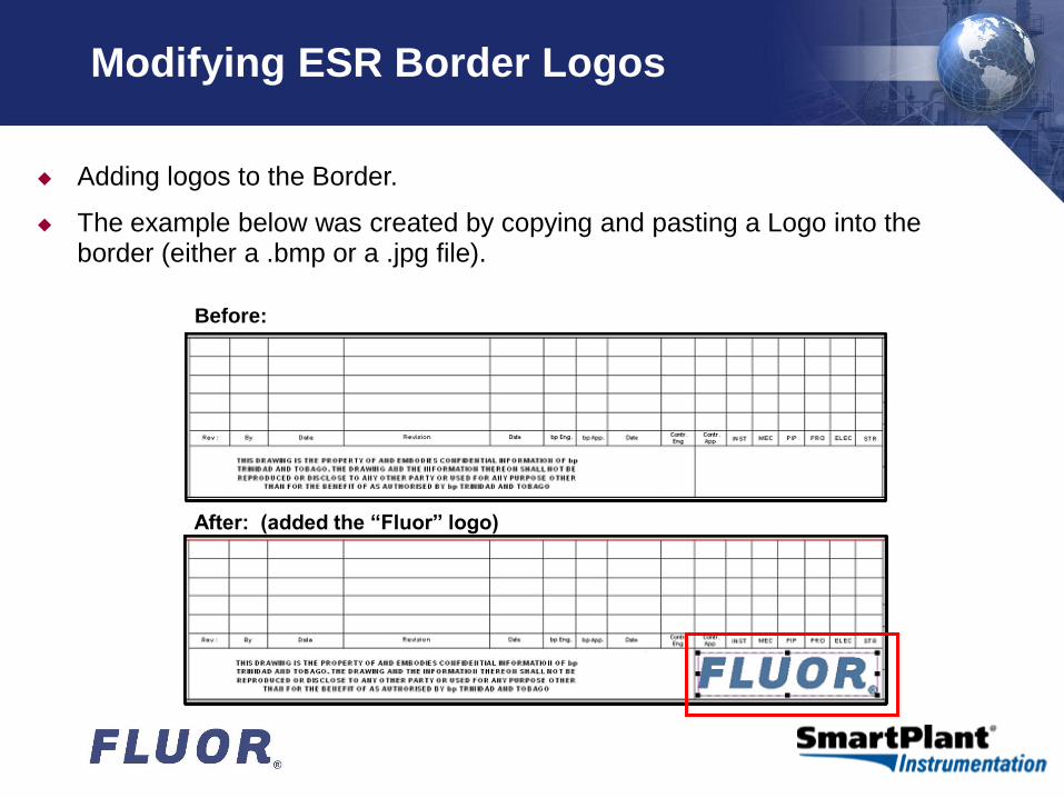
Adding logos to the Border.
The example below was created by copying and pasting a Logo into the border (either a .bmp or a .jpg file).
Before:
After: (added the “Fluor” logo)
AV\filename.ppt 14
Modifying ESR Borders
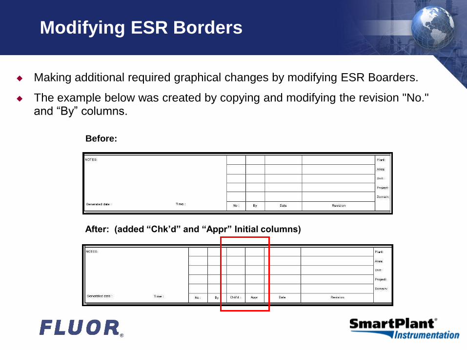
Making additional required graphical changes by modifying ESR Boarders.
The example below was created by copying and modifying the revision "No." and “By” columns.
Before:
After: (added “Chk’d” and “Appr” Initial columns)
AV\filename.ppt 15
Modifying ESR Borders – Copy Macro
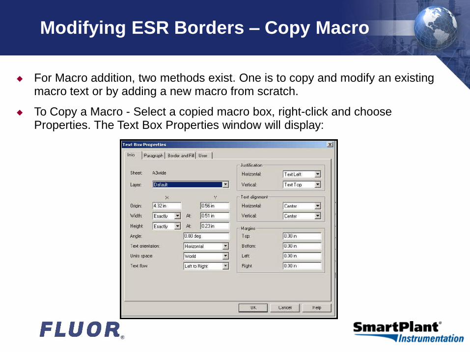
For Macro addition, two methods exist. One is to copy and modify an existing macro text or by adding a new macro from scratch.
To Copy a Macro - Select a copied macro box, right-click and choose Properties. The Text Box Properties window will display:
AV\filename.ppt 16
Modifying ESR Borders – Copy Macro
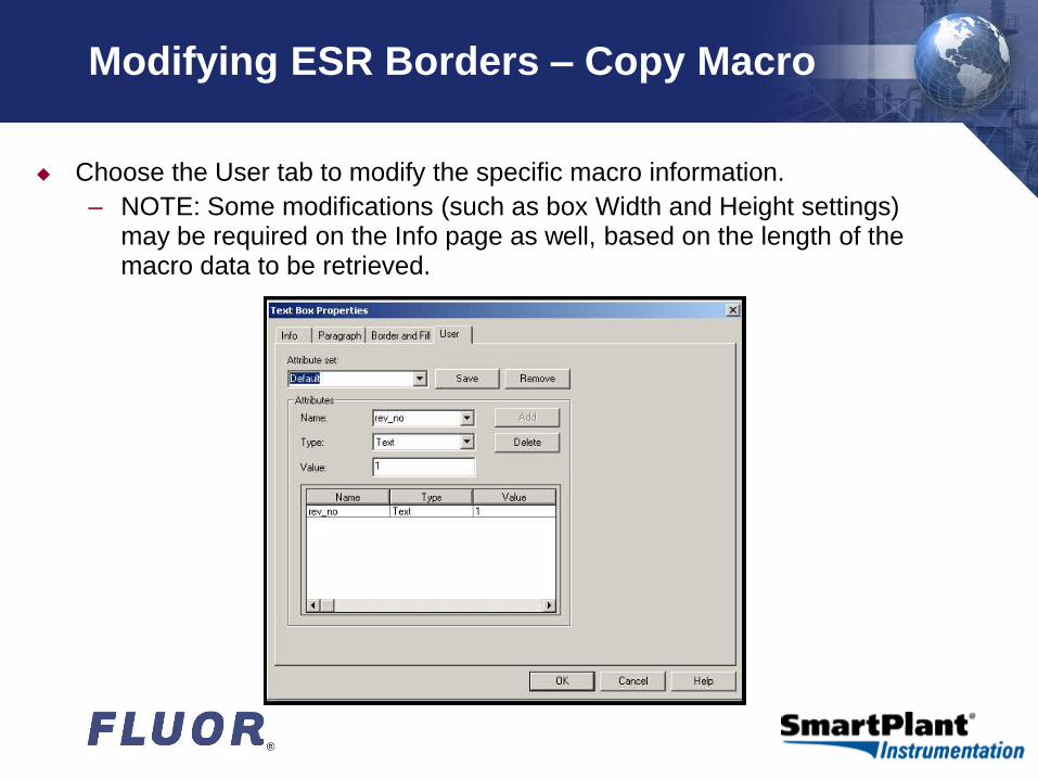
Choose the User tab to modify the specific macro information.
– NOTE: Some modifications (such as box Width and Height settings) may be required on the Info page as well, based on the length of the macro data to be retrieved.
AV\filename.ppt 17
Modifying ESR Borders – Copy Macro
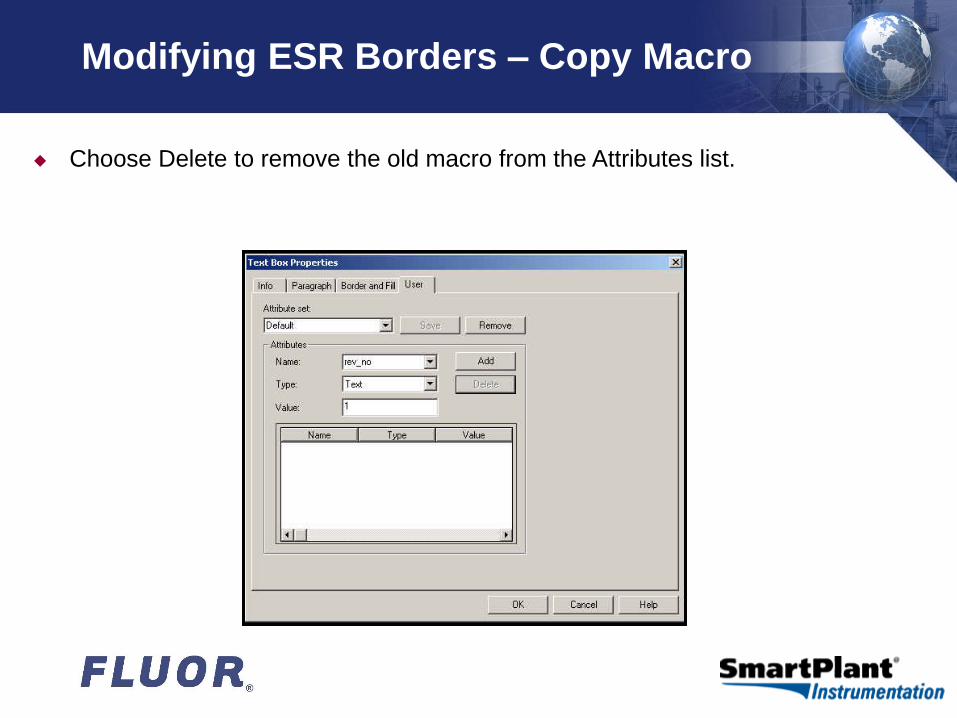
Choose Delete to remove the old macro from the Attributes list.

AV\filename.ppt 18
Modifying ESR Borders – Copy Macro
Enter the new macro name in the Name box and keep the Type as Text.
If the macro is revision related fill in the Value box with the appropriate number, otherwise it should remain blank

AV\filename.ppt 19
Modifying ESR Borders – Copy Macro
Click on the Add button to add the new value to the Attribute list for the selected set.
Click OK when done!
AV\filename.ppt 20
Modifying ESR Borders – New Macro
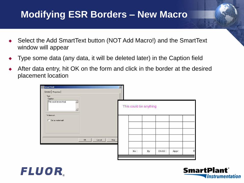
Select the Add SmartText button (NOT Add Macro!) and the SmartText window will appear
Type some data (any data, it will be deleted later) in the Caption field
After data entry, hit OK on the form and click in the border at the desired placement location

AV\filename.ppt 21
Modifying ESR Borders – New Macro
Select the newly placed SmartText item and right-click. Choose Properties to open the Text Box Properties form

AV\filename.ppt 22
Modifying ESR Borders – New Macro
Switch to the User tab to define the actual Macro text you wish to apply to this field:
AV\filename.ppt 23
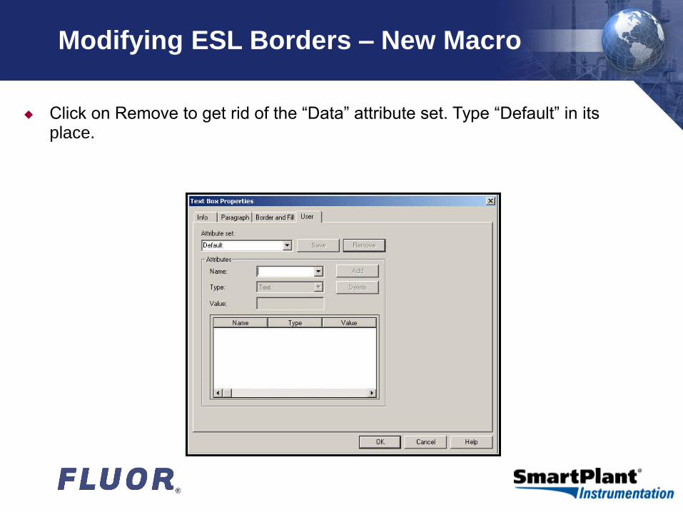
Modifying ESL Borders – New Macro
Click on Remove to get rid of the “Data” attribute set. Type “Default” in its place.
AV\filename.ppt 24
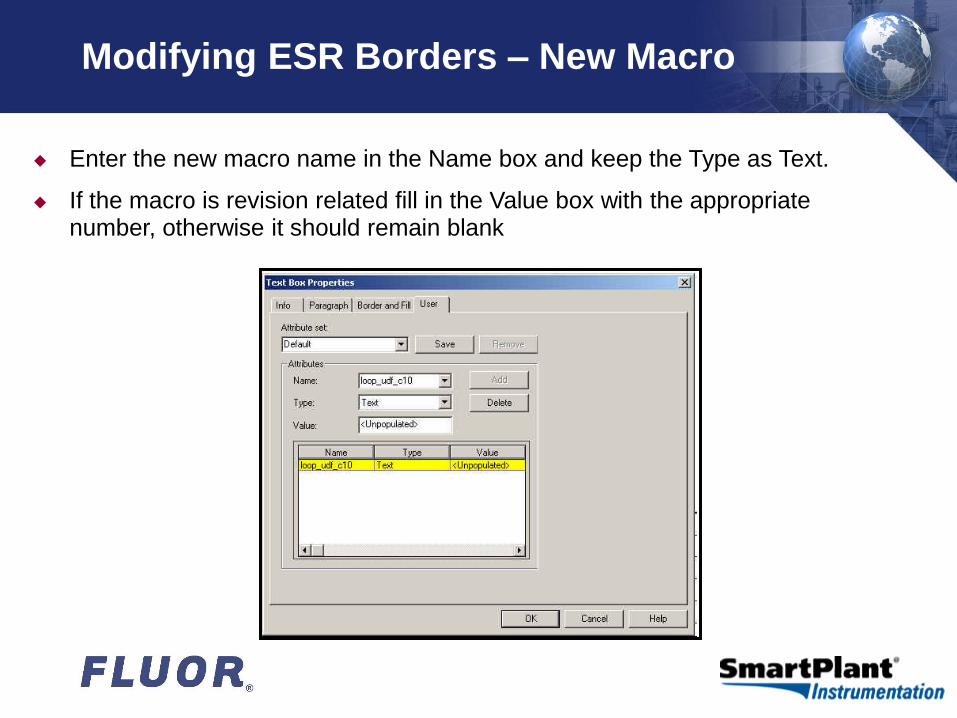
Modifying ESR Borders – New Macro
Enter the new macro name in the Name box and keep the Type as Text.
If the macro is revision related fill in the Value box with the appropriate number, otherwise it should remain blank

AV\filename.ppt 25
Modifying ESR Borders – New Macro
Click the Add button to add the new value to the Attribute list for the selected set.
New sets can be created if desired.
Choose OK when done and Save the new Attribute set.
Remove any text you may have placed in the SmartText box as a placeholder

AV\filename.ppt 26
Customizing ESR Borders
When alterations/additions are complete,
SWITCH THE VIEW BACK TO THE WORKING SHEET
NOTE: Failure to do the will result in generated ESR wiring to not appear completely. Typical indication of this is that the document will only display the first device panel.

AV\filename.ppt 27
Customizing ESR Borders
Save the changes you made to normal.sma.
Select a Loop and generate a test Enhanced SmartLoop Drawing.
Check your results:
AV\filename.ppt 28
Customizing ESL Borders
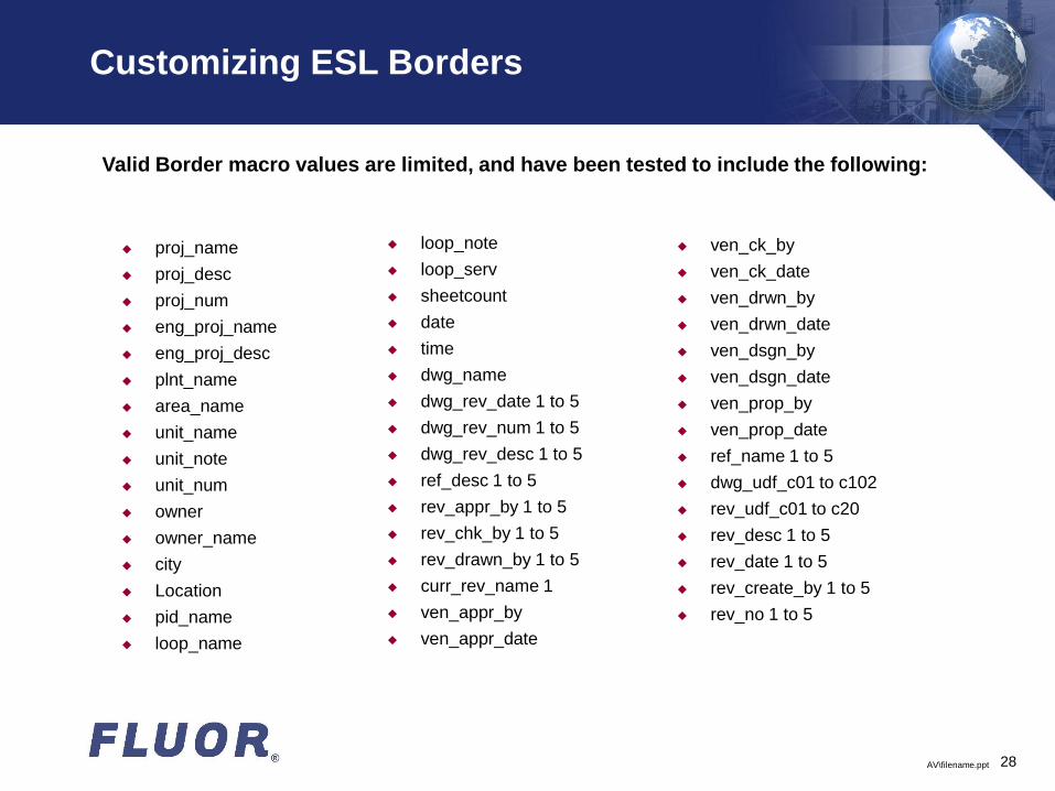
proj_name
proj_desc
proj_num
eng_proj_name
eng_proj_desc
plnt_name
area_name
unit_name
unit_note
unit_num
owner
owner_name
city
Location
pid_name
loop_name
Valid Border macro values are limited, and have been tested to include the following:
ven_ck_by
ven_ck_date
ven_drwn_by
ven_drwn_date
ven_dsgn_by
ven_dsgn_date
ven_prop_by
ven_prop_date
ref_name 1 to 5
dwg_udf_c01 to c102
rev_udf_c01 to c20
rev_desc 1 to 5
rev_date 1 to 5
rev_create_by 1 to 5
rev_no 1 to 5
loop_note
loop_serv
sheetcount
date
time
dwg_name
dwg_rev_date 1 to 5
dwg_rev_num 1 to 5
dwg_rev_desc 1 to 5
ref_desc 1 to 5
rev_appr_by 1 to 5
rev_chk_by 1 to 5
rev_drawn_by 1 to 5
curr_rev_name 1
ven_appr_by
ven_appr_date
AV\filename.ppt 29
Customizing ESL Templates & Borders
Questions & Comments
presentation by: John Dressel, Fluor
based on a paper by: Scott Ambrose, Intergraph