enhancement of voltage stability by using · pdf fileenhancement of voltage stability by using...
TRANSCRIPT

International Journal of Electrical, Electronics and Data Communication, ISSN: 2320-2084 Volume- 1, Issue- 7, Sep-2013
Enhancement of Voltage Stability By Using Facts Under Normal and Transient Conditions
81
ENHANCEMENT OF VOLTAGE STABILITY BY USING FACTS UNDER NORMAL AND TRANSIENT CONDITIONS
1K. VENKATA RAMANA REDDY, 2M. PADMA LALITHA, 3P.HARSHA VARDHAN REDDY
M.Tech. Student, Annamacharya Institute of Technology and sciences, Rajampet,
Kadapa (DT), AP (ST), India M.Tech. , Ph.D., Professor& Head of the Department, Department of EEE, Annamacharya Institute of Technology and
sciences, Rajampet, Kadapa (DT), AP (ST), India M.Tech., Asst.Professor, Department of EEE, Annamacharya Institute of Technology and sciences, Rajampet, Kadapa (DT),
AP (ST), India Email: [email protected]
Abstract: In this paper an IEEE standard test system has been considered and Load flows were computed by using Newton Raphson method with the help of MATLAB and a weak bus is identified. The bus that is with a low voltage magnitude is incorporated with FACTS devices namely TCSC and SVC in order to improve the voltage under normal conditions. Then the reactive power at a particular bus is increased until it reaches to the instability point and the voltage stability condition is evaluated by using an L- index method. The values which approach unity imply that it reaches to instability, and corresponding bus can be treated as weak bus i.e. with a highest value of L-index, and is incorporated with FACTS devices to enhance the voltage stability under transient condition also. Keywords: L-index, SVC, TCSC, MATLAB I. INTRODUCTION As a result of ever-increasing demand of electric power, the electricity supply industry is undergoing profound transformation worldwide. This makes the existing power transmission system highly complex. To meet the increasing demand of electricity in a power system it is essential to increase the transmitted power either by installing new transmission lines or by improving the existing transmission lines by adding new devices. Installation of new transmission lines in a power system leads to the technological complexities such as economic and environmental considerations that includes cost, delay in construction as so on. Flexible alternating current transmission system (FACTS) technology gave up new ways for controlling power flows and enhancing the usable capacity of transmission lines. FACTS are system comprised of static equipment used for the AC transmission of electrical energy. It is meant to enhance controllability and increasing the power transfer capability of the power system network. The concept of FACTS was first defined by N.G. Hingorani in 1988. It usually refers to the application of high power semi conductor devices to control different parameters and electrical variables such as voltage, impedance, and phase angle, current, active and reactive power. This paper addresses the static modeling of Static Var Compensator (SVC) and Thyristor Controlled Series Compensator (TCSC), and their capabilities to improve the voltage profile by using MATLAB code. II. VOLTAGE STABILITY INDEX:
In order to prevent the occurrence of voltage collapse, it is essential to accurately predict the operating condition of a power system. Kessel et al. developed a voltage stability index based on the solution of the power flow equation. The L-index is a quantitative measure for the estimation of the distance of actual state of the system stability limit. The L- index describes the stability of the complete system. A load flow result is obtained for a given system operating condition which is otherwise available from the output of an on line estimator. The load flow algorithm incorporates load characteristics and generator control characteristics. For an n-bus power system, buses can be separated into two groups: Bring all load buses to the head and denote them as α L and put the PV buses the tail and term them as α G i.e., α L ={1,2,…,n L} and αG ={ nL+1, nL+2,……n-1, n} Where, nL is the number of load buses. The following hybrid system equation is then obtained:
)1(
G
L
GG
LG
GL
LL
G
L
VI
YF
KZ
IV
Where, ZLL, FLG, KGL, and YGG are sub-block of matrix H; VG, IG, VL, IL are voltage and current vector of PV buses and load buses. Voltage stability index Lj for any load bus can be defined as given below.
International Journal of Electrical, Electronics and Data Communication, ISSN: 2320-2084 Volume- 1, Issue- 7, Sep-2013
Enhancement of Voltage Stability By Using Facts Under Normal and Transient Conditions
82
)2(11
g
i VjViFjiLj
III. STATIC VAR COMPENSATOR SVC can be defined as a shunt connected static var generator or absorber whose output is adjusted to exchange capacitive or inductive current so as to maintain or control specific parameters of the electrical power system (typically bus voltage). SVCs are primarily used in power systems for voltage control or for improving system stability. The advanced models depart from the conventional generator-type representation of the SVC and are based instead on the variable shunt susceptance concept. In the latter case, the SVC state variables are combined with the nodal voltage magnitudes and angles of the network in a single frame of reference for unified, iterative solutions using the Newton–Raphson method. Shunt Variable Susceptance Model In practice the SVC can be seen as an adjustable reactance with either firing-angle limits or reactance limits. The equivalent circuit is used to derive the SVC nonlinear power equations and the linearised equations required by Newton’s method.
Fig.1. variable shunt susceptance model
The linearised equation is given by,
)3(0
00
SVCSVC
k
k
k
BBQQP
k
At the end of iteration (i), the variable shunt susceptance BSVC is updated as follows,
)4(1)(1 iSVC
iSVCSVC
iSVC
iSVC BBBBB
IV. THYRISTOR CONTROLLED SERIES COMPENSATOR
A TCSC can be defined as a capacitive reactance compensator which consists of a series capacitor bank shunted by a thyristor-controlled reactor in order to provide a smoothly variable series capacitive reactance. The basic conceptual TCSC module comprises a series capacitor, C, in parallel with a thyristor-controlled reactor, LS, as shown in Fig.2
Fig. 2 Thyristor-controlled series compensator
Variable Series Impedance Power Flow Model The TCSC power flow model presented in this section is based on the simple concept of a variable series reactance, the value of which is adjusted automatically to constrain the power flow across the branch to a specified value. The amount of reactance is determined efficiently using Newton’s method. The changing reactance XTCSC represents the equivalent reactance of all the series-connected modules making up the TCSC, when operating in either the inductive or the capacitive regions. The transfer admittance matrix of the variable
series compensator is given by
)5(
m
k
mm
km
mk
kk
m
k
VV
jBjB
jBjB
II
For the power equations at bus m, the subscripts k and m are exchanged and the active and reactive power equations at bus k are
)6()cos(
)sin(2
mkkmmkkkkk
mkkmmkk
BVVBVQ
BVVP
V. RESULTS AND DISCUSSION
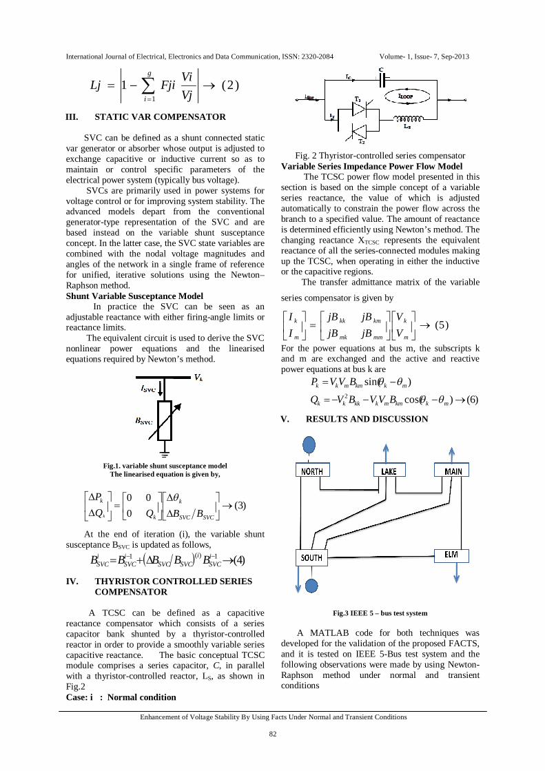
Fig.3 IEEE 5 – bus test system
A MATLAB code for both techniques was developed for the validation of the proposed FACTS, and it is tested on IEEE 5-Bus test system and the following observations were made by using Newton-Raphson method under normal and transient conditions
Case: i : Normal condition

International Journal of Electrical, Electronics and Data Communication, ISSN: 2320-2084 Volume- 1, Issue- 7, Sep-2013
Enhancement of Voltage Stability By Using Facts Under Normal and Transient Conditions
83
Table: 1 Under Normal condition
After running the power flow by using Newton- Raphson method on an IEEE standard test system (5 -bus), a weak bus is identified. Under normal condition with SVC it is found that the voltage profile at bus 5 where SVC is connected is improved. Initially under normal condition without SVC the voltage magnitude in per unit (pu) at bus 5 is 0.9776, and the L-index of corresponding bus5 is
0.0328, but after placing SVC, voltage magnitude improved to 1.000 pu and the L-index of corresponding bus 5 is 0.0099. Similarly after placing TCSC, the voltage profile at bus 5 is also improved to 0.9789 pu as shown in table-1. The L- index value of each load bus is performed as shown in table-2.
Table: 2. L-Indices
Case: ii: Transient condition
Table: 3 Under Transient condition
Bus no
Voltage magnitude without SVC (OR)
TCSC
Voltage magnitude with SVC
Voltage magnitude with TCSC
1 1.0600 1.0600 1.0600
2 1.0000 1.0000 1.0000
3 0.9925 0.9956 0.9966
4 0.9894 0.9934 0.9924 5 0.9776 1.0000 0.9789
6 0.9784
Bus no L-index
Without SVC (or) TCSC
L-index
With SVC
L-index
With TCSC
3 0.0299 0.0262 0.0296
4 0.0304 0.0267 0.0324
5 0.0328 0.0099 0.0234
6 ------ ------- 0.0536
Bus no
Voltage magnitude without SVC (OR) TCSC
Voltage magnitude with SVC
Voltage magnitude with TCSC
1 1.0600 1.0600 1.0600
2 1.0000 1.0000 1.0000
3 0.9899 0.9967 0.9900
4 0.9860 0.9948 0.9856
5 0.9639 1.0000 0.9641
6 ----------- ----------- 0.9631

International Journal of Electrical, Electronics and Data Communication, ISSN: 2320-2084 Volume- 1, Issue- 7, Sep-2013
Enhancement of Voltage Stability By Using Facts Under Normal and Transient Conditions
84
Then by changing reactive power at bus 5, i.e. from Q= 0.05 to Q =0.2 MVAR, a weak bus is identified as bus 5 and it is incorporated by SVC and TCSC in order to improve the voltage profile as shown in table-3.
The L-index of each load bus was performed with and without SVC as well as TCSC under transient condition as shown in table- 4.
Table: 4 .L- Indices
CONCLUSION This paper depicts that the improved voltage profile of the power system under Normal and Transient conditions with the incorporation of Static VAR compensator (SVC) and Thyristor Controlled Series Compensator (TCSC). SVC and TCSC were able to regulate the bus voltage magnitude at which it is connected over its full range of operation when there isa need. The optimal location is identified by using L-index method. This can also be performed by using Fast decoupled method to analyse the transient stability due to change in real power. REFERENCES
(1) “Enhancement of Voltage Stability through Optimal Placement of Facts Controllers in Power Systems by * Kiran Kumar kuthadi * American Journal of Sustainable Cities and Society*Issue 1 vol 1 July 2012.
(2) “Power electronics in electrical utilities: role of power electronics in future power systems,” *N. G. Hingorani * Proceedings of the IEEE Vol. 76 No.4, pp.481-482, Apr. 1988.
(3) G. W. Stagg, and A. H. El-Abiad, “Computer Methods in Power System Analysis”, McGraw-Hill, 1968
(4) “Analysis of Voltage Stability Using L-Index Method” by I. Kumarswamy¹ and Prof. Dr. P. Ramanareddy², April 2011* Copyright @2011, ECO Services International.
(5) “FACTS modeling and simulation in power networks” by Enrique Acha: University of Glasgow, UK.
(6) ‘International Journal of Electronics and Computer Science Engineering’-2277-1956 : ISSN-2277-1956/V2N2-671-677” “ Enhancement of Voltage Stability through Optimal Location of SVC ” S. B. Bhaladhare 1, P.P. Bedekar 2
(7) “Enhancement of Voltage Stability through Optimal Location of SVC” S. B. Bhaladhare1, P.P. Bedekar 2: ISSN 2277-1956/V2N2-671677IJECSE, Volume2, Number 2S. B. Bhaladhare et al.
(8) “Steady-State Modeling of SVC and TCSC for Power Flow Analysis” Mohammed Osman Hassan, S. J. Cheng, Senior Member, IEEE, Zakaria Anwar Zakaria::Proceedings of the International Multi Conference of Engineers and Computer Scientists 2009 Vol II -IMECS 2009, March 18 - 20, 2009, Hong Kong
Bus no L-index Without SVC (or) TCSC
L-index With SVC
L-index With TCSC
3 0.0326 0.0255 0.0365
4 0.0338 0.0247 0.0396 5 0.0475 0.0099 0.0391 6 --------- 0.0702