enhancing fatigue lifetimes and precision...
TRANSCRIPT

Enhancing Fatigue Lifetimes and Precision Component
Shaping by Laser Peening
Prepared for OSD - JTEG November 26, 2013
Jon Rankin, Jack Campbell and Lloyd Hackel Metal Improvement Company

- 2
Presentation outline
• Background on laser peening
• Current commercial and military applications
• Engineering residual stress and strain through finite element analysis of laser peening
• Case studies in fatigue and forming applications

- 3
Laser Peening employs advanced laser technology and shock physics
• Plasma pressure plastically compresses metal in normal direction
• Metal expands transversely to conserve volume
• Surrounding material resists, setting up compressive field
• Compensating tensile stress develops safely subsurface
Laser input Plasma
ε0
ε1>ε0

- 4
Deeper compressive stress provides greater resistance to fatigue and corrosion failure
Laser peening shot peening
Laser peening compressive stress in aluminum is 10x deeper than shot peening

- 5
95
90
85
80
75
70
65
60
555010,000 100,000 1,000,000 10,000,000
Fatigue Life-Cycles
Stre
ss -
MPa
Comparison - Laser peening versus conventional shotpeening on Laser drilled holes in aluminum
LasershotSM
Peened
Control Group
ConventionallyShot Peened
Laser peening enables as much as 10x lifetime improvement for fatigue
Deeper level of residual stress greatly enhances fatigue lifetime of beyond that of conventional surface treatments
Str
ess
(M
Pa
)
6061-T6 Aluminum Laser peened area
(both sides)
4 inches

- 6
Average Crack Growth Rate Between Basemetal GBP & LSP
0.00
0.01
0.02
0.03
0.04
0.05
0.06
0.00 0.50 1.00 1.50 2.00 2.50 3.00 3.50Lives
Cra
ck L
engt
h (in
.
Basemetal
Glass Bead Peen
Laser Peen
5X
Laser peening increases life by 5X compared to either base metal or glass bead peening in Ti6/4.
Cantilever beam specimen mimics stress concentration in component.
F-22 structure development - Laser peening delays crack initiation and growth rate

- 7

- 8
Laser peening is being applied to eliminate fatigue failure in high value commercial jet engines. See Australian Transportation Safety Board Report 8/01 “Examination of a Failed Blade …. Boeing 777-300, A6-EMM” http://www.atsb.gov.au/aviation/tech-rep/8-01/8-01_Final.pdf)
Solving the fatigue failure of Ti engine blades launched laser peening in 2002

- 9
Laser peening extends lifetime of commercial jet engine blades by > 20x – saves $Ms annually
Boeing 777 with MIC laser peened
blades
Over 40,000 blades have been treated for engines powering Boeing 777s , A340s and the new Boeing 787s and A350s
0.2
0.3
0.4
0.5
0.6
0.7
0.8
100 1000 10000 100000
Life (cycles)
Equ
ival
ent A
f (m
Hz)
Conventional Peen
Deep Cold Rolled
LSP (New)
LSP (Pre-Fatigued)
Lifetime
Str
ess

- 10
MIC laser peening forms thick sections of wing panels for the new 747-8
Wing skin panels are in laser peen forming production
World’s first aircraft with laser formed panels delivered 2011

- 11
Transportable laser peening systems enable field applications such as F-22 crack prevention
Completely self-contained, the transportable system needs only electrical power, compressed air and water (~1gpm)
MIC’s unique high power laser

- 12
MIC laser peening can be done at overhaul facilities
• Laser peening can be easily transported to facilities for on-site processing • F-22 processing moving to Hill AFB

- 13
Test results for F-22 structure show significant improvement from Laser Peening
Laser peening deployed on F-22 at Lockheed Palmdale in April 2011
*GBP = glass bead peening, LSP = Laser shock peening

- 14
Laser peening of integrally bladed rotors (IBRs) is fully qualified and in production for commercial aircraft engines
Robotics maintain precision process control
Set up and peening is a straightforward extension of the well developed production process.
IBR handling robot
Tamping layer water robot
Laser beam director robot

- 15
Laser peening technology has been developed and qualified for production IBR work
Peening of IBRs for fatigue crack and FOD protection would generate an operational cost reduction for F-135 deployment

- 16
An opportunity: Laser peening of F-16 structure can minimize replacements and costs – could be done at Hill AFB at low cost
ZONE P/N Designation Work Type
FS 309.80 16B5231-888 UPPER BULKHEAD REWORK
FS 325.80 16B5241-827 LH - UPPER BULKHEAD
REWORK
FS 325.80 16B5241-828 RH - UPPER BULKHEAD
REWORK
FS 341.80 16B5251-737 UPPER BULKHEAD REWORK
FS 357.80 16B5261-883 UPPER BULKHEAD REWORK
FS 309.80 16B5232-807 LH - LOWER BULKHEAD
REWORK
FS 309.80 16B5232-808 RH - LOWER BULKHEAD
REWORK
FS 325.80 16B5242-805 LOWER BULKHEAD REWORK
FS 357.80 16B5262-847 LOWER BULKHEAD REWORK
FS 341.80 16B5250-551 LOWER BULKHEAD NEW
FS 446.1 16B6211-123 UPPER BULKHEAD REWORK
FS 446.1 16B6212-91 LOWER BULKHEAD NEW
FS 462.80 16B6215-25 BULKHEAD REWORK
FS 479.55 16B6223-69 UPPER BULKHEAD NEW

- 18
Presentation outline
• Background on laser peening
• Current commercial and military applications
• Engineering residual stress and strain through finite element analysis of laser peening
• Case studies in fatigue and forming applications

description - #19
Laser peening for fatigue and forming
• Overview of process modeling
• Case studies in laser peening for fatigue – T45 hook
– F35 hook
– F-18 Y508 shear tie
• Laser peening for forming and form correction – Forming of integrally stiffened panels
– Forming and correction of thin panels
• Program pay-off

description - #20
Overview of modeling concept
• Analysis input is computed from experimental measurements
• Part is modeled using continuum (3D) elements in ABAQUS
• Set a thermal initial condition based on Eigenstrain and let the model equilibrate – result shows the new shape and stress state of the part

description - #21
Example: FEA model of laser peening a simple block
Thermal input in
/in
S11
S22
Resulting stresses
ksi
ksi
Simulate peening a patch on a block (with symmetry)
Results can be interrogated for stress, strain or displacement
Laser peening

description - #22
FEA simulation of a fatigue specimen
Laser peening pattern
Without peening, under load
Effect of laser peening (without load)
Without peening – Peak axial stress is 183 ksi
With laser peening – Peak axial stress is 132 ksi
FEA predicts a 28% reduction in peak stress by laser
peening the stress riser

description - #23
FEA predicts 28% reduction in peak RS with laser peening
-200
-150
-100
-50
0
50
100
150
200
250
-0.3 -0.2 -0.1 0 0.1 0.2 0.3
Stre
ss (k
si)
Y position (inch)
Axial stress (unpeened)
Axial stress (peened)
Peening RS (no load)
Without peening – Peak axial stress is 183 ksi
With laser peening – Peak axial stress is 132 ksi
Effect of laser peening (without load)

description - #24
Laser peening for fatigue and forming
• Overview of process modeling
• Case studies in laser peening for fatigue – T45 hook
– F35 hook
– F-18 Y508 shear tie
• Laser peening for forming and form correction – Forming of integrally stiffened panels
– Forming and correction of thin panels
• Program pay-off

description - #25
Case study: T45 hook shank
OEM provided elastic FEA data for the hook shank and a solid model

description - #26
Case study: T45 hook shank
OEM provided elastic FEA data for the hook shank and a solid model

description - #27
Modeling is integral for implementing laser peening
Develop treatment using customer’s CAD model as input
Computer generated peening control code
Validation testing of service components
Establish peening parameters using blocks of the material of interest
Testing of coupons in representative service condition
Treatment of actual components

description - #28
Use finite element analysis to design a test coupon
0.0 0.1 0.2 0.3 0.4 0.5 0.6 0.7
DEPTH BELOW NOTCH (in.)
0
50
100
150
200
250
300
STRE
SS (k
si)
MIC MODEL(DEPRESSION WITH BOSS)
BOEING MODEL(99.9th PERCENTILE LOAD)
B = 0.5 in.P = 33.34 kips
(INNER NOTCH)
B = 0.5 in.P = 33.34 kips
(OUTER NOTCH)
17”

description - #29
Coupon testing at NAVAIR - Pax River
• Tested at NAVAIR on a 100 kip fatigue frame with OEM provided load spectrum
• Each application of the spectrum represented 102 arrestments
• After each spectrum pass the coupon was examined under load and magnification for cracks
• Any visually detectable crack terminates the test

description - #30
Fatigue results: LP gives 2.5x life improvement
• Performing S-basis estimate for crack initiation life results in:
– 439 arrestments for unpeened (1x)
– 423 arrestments for shot peened (0.97x)
– 1102 arrestments for laser peened (2.5x)
• Analysis generalizes performance of large population of tests from limited testing
0 1000 2000 3000 4000
CRACK INITIATION LIFE(SIMULATED ARRESTMENTS)
0.05
0.10
0.50
CUMU
LATI
VE P
ROBA
BILI
TY
0 1 2 3 4RELATIVE CRACK INITIATION LIFE
UNPEENEDSPECIMENS(BASELINE)
CONVENTIONALLYSHOT PEENEDSPECIMENS
LASER SHOCKPEENED SPECIMENS
0.90

description - #31
T45 hook shank is now in production in Livermore CA

description - #32
Laser peening for fatigue and forming
• Overview of process modeling
• Case studies in laser peening for fatigue – T45 hook
– F35 hook
– F-18 Y508 shear tie
• Laser peening for forming and form correction – Forming of integrally stiffened panels
– Forming and correction of thin panels
• Program pay-off

description - #33
Case study: F35 hook shank – T45 used as roadmap for program
0
0.1
0.2
0.3
0.4
0.5
0.6
0.7
0.8
0.9
1
0 5000 10000 15000 20000
Cum
ulat
ive
Prob
abili
ty (S
urvi
val)
Crack Initation Life (Simulated Arrestments)
Baseline
SP
SP/LP
description - #34
Laser peening for fatigue and forming
• Overview of process modeling
• Case studies in laser peening for fatigue – T45 hook
– F35 hook
– F-18 Y508 shear tie
• Laser peening for forming and form correction – Forming of integrally stiffened panels
– Forming and correction of thin panels
• Program pay-off

description - #35
Case study: F-18-Y508 Shear Tie is a fatigue life limit for useful lifetime of aircraft
Y508 former shear tie provides
critical load transfer
from wing to fuselage
Replacing shear tie bulkhead has serious consequences for overhaul costs

description - #36
Laser peening dramatically increases depth of compressive residual stress
o As-machined and surface pickled (per NAVAIR spec)
o Ion vapor deposition coating (IVD)
o Shot peen (SP)* then IVD coating (current Y508 treatment)
o Shot peen* IVD coating then Laser peen (LP)**
*Shot peen: per PS14023 at 0.006-0.010A intensity, 230-280 shot ** Laser peen: 4GW/cm2, 18ns, 3-layers, tape
RS vs. depth for three post-treatment processes used on the Y508 coupons
-60
-50
-40
-30
-20
-10
0
10
0 0.01 0.02 0.03 0.04
Stre
ss (k
si)
Depth (in)
As machined (range)
IVD
SP, IVD
SP, IVD,LP

description - #37
We adopted a uniaxial “dual-sided” coupon design to simulate the shear tie hot-spot
Benefits of dual-sided design • Accurate simulation of shear tie
compressive and tensile bending stresses (at surface and vs. depth)
• Relative ease of fabrication and post processing
• Modest displacement allows high test rate (~5-6Hz)
• Sufficient access for laser peening
• Symmetric uniaxial loading on fatigue test system

description - #38
Fracture face mapping enables crack growth measurements
• Optical microscopy used to map fracture faces and show basic features – specimen cross-section
– terminal crack front
– location where crack growth curves were extracted
– crack origins
– other features of interest

description - #39
Key result: Without exception, laser peening offers significant life improvement over other processes
Results from crack growth measurements: Addition of LP to SP+IVD improves life by 1.6 to 5.5X over SP+IVD alone
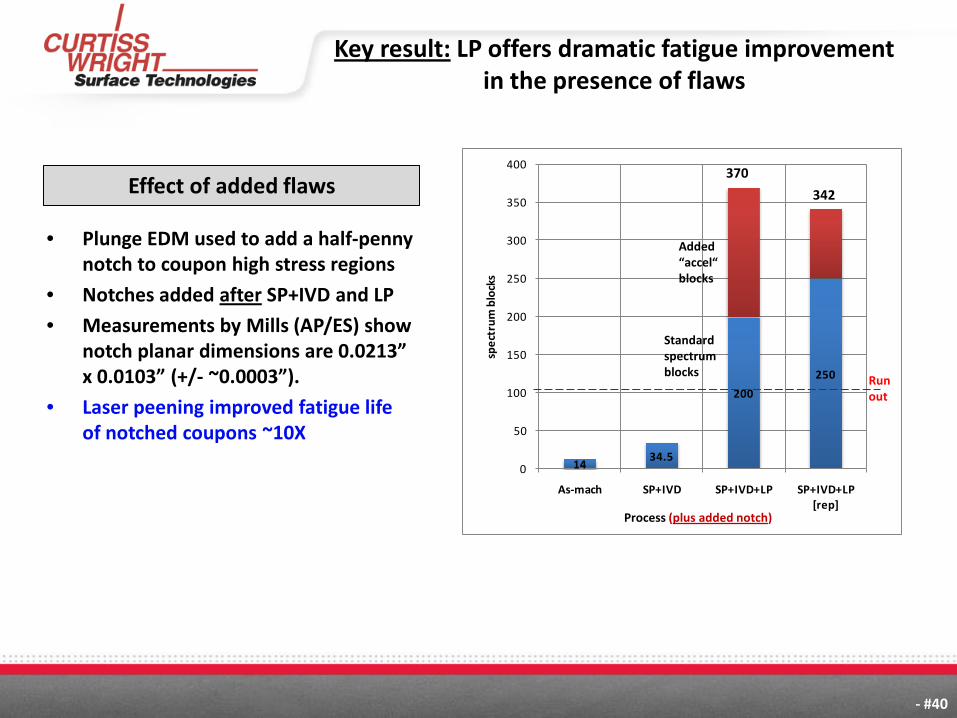
description - #40
1434.5
200
250
0
50
100
150
200
250
300
350
400
As-mach SP+IVD SP+IVD+LP SP+IVD+LP [rep]
spec
trum
blo
cks
Process
Added “accel“ blocks
Standard spectrum blocks
Run out
370
342
Process (plus added notch)
• Plunge EDM used to add a half-penny notch to coupon high stress regions
• Notches added after SP+IVD and LP
• Measurements by Mills (AP/ES) show notch planar dimensions are 0.0213” x 0.0103” (+/- ~0.0003”).
• Laser peening improved fatigue life of notched coupons ~10X
Key result: LP offers dramatic fatigue improvement in the presence of flaws
Effect of added flaws

description - #41
Laser peening for fatigue and forming
• Overview of process modeling
• Case studies in laser peening for fatigue – T45 hook
– F35 hook
– F-18 Y508 shear tie
• Laser peening for forming and form correction – Forming of integrally stiffened panels
– Forming and correction of thin panels
• Program pay-off

description - #42
Case study: Laser-peen-forming (LPF) integrally stiffened panels
• Curtiss Wright was funded by the US Air Force* to demonstrate laser-peen-forming integrally stiffened panels.
* AFMC AFRL/RXMP : Project oversight Howard Sizek
(a) As Received (b) After LP
Z height in inches
ROC ~ 26”
ROC ~ 33”
ROC ~ -200”
Example of laser peen forming a flat integral-stringer panel into conical shape
Contour plots show the panel shape (a) before and (b) after LP.

description - #43
Simple tooling and fixtures enable rapid demonstration and proto-typing
• Low cost
• High strength
• Light weight
• Rapid fabrication
• Easily modified/adapted
Wood forms offer several advantages:
Panel on from in LP process cell
Panel in cell during process

description - #44
Case Study: LP forming integrally stiffened panel with reinforced cut-out
Goal: LP form panel to cylindrical shape (40” ROC)
As-received panel
L-stringer
blade-stringer
Door frame openingcut out
CAD model of panel
“Single-step” milled pocket
“Double-step” milled pocket
Thickest material at corner of openingPanel has significant
stiffener thickness variations around the
cut-out

description - #45
“Cut-out” panel ready for LP
Al-tape ablator applied to surface
Full-length bar tie down
Tie down clips
48” ROC cylindrical pre-stress form
(wood)
Panel material:Aluminum 2024-T351
Top-half peened first, then bottom-half

description - #46
LP of thicker material near the cut out
(b) After LP of thick region
Laser peened patch: 2-layers of LP at
1.4GW/cm2
Approx area to be
laser peened
High-radius tool used to treat thick area (ROC~ 9-16”)
(a) Before LP of thick region
Again note the use of simple, low cost, fixtures enabling rapid proto-typing
with LP forming

description - #47
ISP panel with cut-out after LP forming
(a)
inches
inch
es
Height - inches
In shipping box and ready to ship to customer
(b)
description - #48
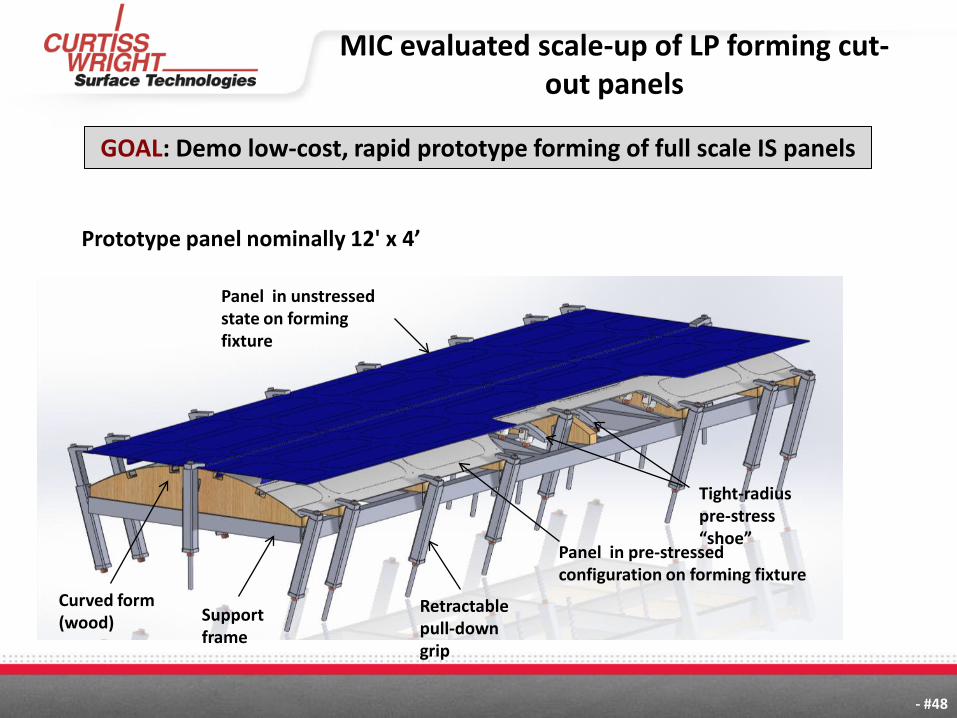
MIC evaluated scale-up of LP forming cut-out panels
Support frame
Panel in unstressed state on forming fixture
Panel in pre-stressed configuration on forming fixture
Retractable pull-down grip
Curved form (wood)
Tight-radius pre-stress “shoe”
Support frame
Prototype panel nominally 12' x 4’
GOAL: Demo low-cost, rapid prototype forming of full scale IS panels

description - #49
LP forming IS panels: conclusions
• Laser peen forming has been demonstrated to custom-shape integrally stiffened panels (ISP) for advanced aircraft fabrication.
• Panels containing L, J or T types of stringers as well as stiffened pocket regions were supplied by OEM’s with specific advanced forming applications and goals.
• This work lead to our contact with Chris Root at NAVAIR FRC-SW
In 2012 NAVAIR inquired about LP corrective-forming of 701
fuselage skin panels on the F-18

description - #50
Laser peening for fatigue and forming
• Overview of process modeling
• Case studies in laser peening for fatigue – T45 hook
– F35 hook
– F-18 Y508 shear tie
• Laser peening for forming and form correction – Forming of integrally stiffened panels
– Forming and correction of thin panels
• Program pay-off

description - #51
A number of F-18 701 skins require form correction
701-skin
As rec’d panel for LP forming correction

description - #52
MIC has worked with NAVAIR to quantify skin shape departure
Z D
iffe
ren
ce (m
m)
~20”
~9”
Panel ~7 mm above frame
(mm
)
(mm)
Example of one skin that was carefully characterized, showing typical departures

description - #53
Test skins have been received at MIC and were the focus of the NCMS contract effort
(b) Panel installed on fixture
(a) Check fixture
Solid model
As-built fixture

description - #54
A model was needed to simulate LP response of thin panels
• 22”x22” square 0.09” thick Al7075 panel
• Initially flat (measured spherical curvature of R~1500”)
• Generate a LP pattern which produces an asymmetric depression >0.1” – Utilize separated narrow LP rings to minimize shots
Red = IML peening – 332 shots Blue = OML peening – 322 shots
Panel will move towards the IML

description - #55
Forming demonstration tested the model - 22” x 22” panel
inch
22” x 22” panel after laser peening Experimentally scanned shape after laser peening

description - #56
FEA results matched measurement well
FEA simulation result
Experimental measurement
Y-profiles X-profiles 3-d contour
Y-profiles X-profiles 3-d contour

description - #57
Surface stress (XRD) is consistent with model predictions
-4.E+04
-4.E+04
-3.E+04
-3.E+04
-2.E+04
-2.E+04
-1.E+04
-5.E+03
0.E+00
5.E+03
1.E+04
-12 -10 -8 -6 -4 -2 0 2 4 6 8 10 12
Stre
ss (P
SI)
Transverse Position (in)
S11 OML 0.83 S11 OML XRD S22 OML 0.83 S22 OML XRD
-4.E+04
-4.E+04
-3.E+04
-3.E+04
-2.E+04
-2.E+04
-1.E+04
-5.E+03
0.E+00
5.E+03
1.E+04
-12 -10 -8 -6 -4 -2 0 2 4 6 8 10 12
Stre
ss (P
SI)
Transverse Position (in)
S11 IML 0.83 S11 IML XRD S22 IML 0.83 S22 IML XRD
S22 S11
IML
OM
L
S22 S11

description - #58
Laser peening for fatigue and forming
• Overview of process modeling
• Case studies in laser peening for fatigue – T45 hook
– F35 hook
– F-18 Y508 shear tie
• Laser peening for forming and form correction – Forming of integrally stiffened panels
– Forming and correction of thin panels
• Program pay-off

description - #59
The OSD cost-shared 701 skin program has had high pay-off
• Military examples: – Better understanding of IS panel forming – F15 tail actuator – F15 speed brake – A10 re-winging – AH-64 tail mounts – CH-47 side frames – F35 floor panel
• Commercial applications: – Gas turbine hardware – Nuclear reactor weld mitigation – Passenger-to-freighter conversion – Low-cost manufacture of limited production panels (retrofits,
prototypes)