enhancing the supersonic wind tunnel performance based...
TRANSCRIPT

Research ArticleEnhancing the Supersonic Wind Tunnel Performance Based onPlenum Temperature Control
A. Nazarian Shahrbabaki, M. Bazazzadeh, A. Shahriari, and M. Dehghan Manshadi
Department of Mechanical & Aerospace Engineering, Malek-Ashtar University of Technology,Shahin Shahr, Isfahan 83145/115, Iran
Correspondence should be addressed to A. Nazarian shahrbabaki; [email protected]
Received 9 February 2014; Accepted 4 March 2014; Published 2 April 2014
Academic Editors: E. J. Avital and Y. Shi
Copyright © 2014 A. Nazarian shahrbabaki et al.This is an open access article distributed under theCreativeCommonsAttributionLicense, which permits unrestricted use, distribution, and reproduction in anymedium, provided the originalwork is properly cited.
The application of fuzzy logic controllers (FLCs) to the control of nonlinear processes, typically controlled by a human operator, isa topic of much study. In this paper, the design and application of a FLC is discussed to control the plenum chamber temperaturefor a blowdown supersonic wind tunnel (BSWT) with the aim of achieving the accurate and desired results. In this regard, first,a nonlinear mathematical model of special BSWT is developed in Matlab/Simulink software environment. Next, an artificiallyintelligent controller is designed using fuzzy logic approach. For this purpose, a proportional-derivative FLC (PD-FLC) system isdeveloped in the Simulink toolbox to control the plenum stagnation temperature using a heater upstream of the plenum chamber.Finally, the system simulation results inside of the temperature and pressure controllers in comparison with the experimental runare presented. The results for Mach 2.5 blowdown run show the great performance of the Wind Tunnel Simulator Model and itstemperature controller system.
1. Introduction
Blowdown supersonic wind tunnels (BSWTs) deliver flow atconstant stagnation temperature and pressure.The stagnationtemperature is generally regarded to be equal to the plenumtemperature which is controlled by heater upstream of theplenum chamber. During a blowdown run, the storage tanktemperature and pressure that supplies plenum chamberflow decrease continuously. Thus, to maintain a constantplenum pressure as close as possible to a setpoint pressuresignal, the regulator or control valve must open progressively.Besides, to maintain a constant stagnation temperature inthe plenum chamber, a heater must operate continuouslyduring a supersonic run [1–3]. The controller must operateat different stagnation pressures and Mach numbers and hasto be robust to accommodate the varying pressure and massflow requirements safely. New concepts for control are underimplementation with the goal of reducing transition phaseand overall loads on the models [4, 5].
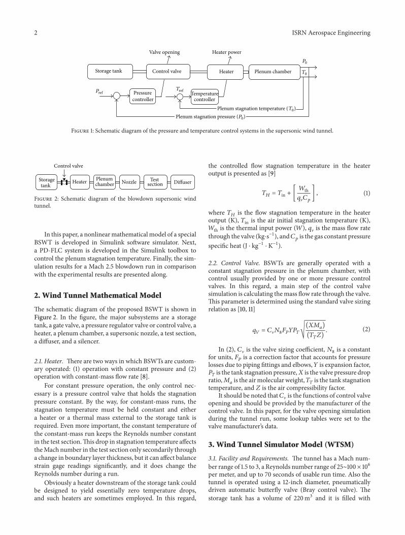
The block diagram of the control systems in the proposedBSWT is illustrated in Figure 1.
Fuzzy logic has been the area of heated debate andmuch controversy during the last decades. The first paper in
fuzzy set theory, which is now considered to be the seminarpaper of the subject, was written by Zadeh et al. [6], whois considered the founding father of the field. In that work,Zadeh was implicitly advancing the concept of approximatehuman reasoning to make effective decisions on the basis ofthe available imprecise, linguistic information.
In the 1970s, King and Mamdani [7] studied the applica-tion of FLCs to the control of nonlinear industrial processesthat typically can only be controlled successfully by a humanoperator. The idea of FLCs has become a common solutionin recent years, with applications ranging from automationof industrial processes to control of electronic devices inconsumer products. The design and application of a FLCfor the control of plenum chamber temperature in severalwind tunnels at NASA’s Langley Research Center (LaRC) inHampton, VA, is described [8].
The intelligent controlling approaches like fuzzy logic(FL) will provide the required scope for wind tunnels to bemore efficient, safe, and economic. The approaches will helpto enable a level of performance that far exceeds that of today’swind tunnel in terms of reduction of harmful emissions,maximization of run time, and minimization of noise, whileimproving system affordability and safety.
Hindawi Publishing CorporationISRN Aerospace EngineeringVolume 2014, Article ID 317049, 6 pageshttp://dx.doi.org/10.1155/2014/317049
2 ISRN Aerospace Engineering
T
Valve opening Heater power
Control valveStorage tank Plenum chamberHeater
Temperature controller
Pressure controller
T0
T0)Plenum stagnation temperature (Plenum stagnation pressure (P0
P0
)
PrefTref
Figure 1: Schematic diagram of the pressure and temperature control systems in the supersonic wind tunnel.
HeaterStorage tank
Plenum chamber Nozzle Test
section Diffuser
Control valve
Figure 2: Schematic diagram of the blowdown supersonic windtunnel.
In this paper, a nonlinearmathematicalmodel of a specialBSWT is developed in Simulink software simulator. Next,a PD-FLC system is developed in the Simulink toolbox tocontrol the plenum stagnation temperature. Finally, the sim-ulation results for a Mach 2.5 blowdown run in comparisonwith the experimental results are presented along.
2. Wind Tunnel Mathematical Model
The schematic diagram of the proposed BSWT is shown inFigure 2. In the figure, the major subsystems are a storagetank, a gate valve, a pressure regulator valve or control valve, aheater, a plenum chamber, a supersonic nozzle, a test section,a diffuser, and a silencer.
2.1. Heater. There are two ways in which BSWTs are custom-ary operated: (1) operation with constant pressure and (2)operation with constant-mass flow rate [8].
For constant pressure operation, the only control nec-essary is a pressure control valve that holds the stagnationpressure constant. By the way, for constant-mass runs, thestagnation temperature must be held constant and eithera heater or a thermal mass external to the storage tank isrequired. Even more important, the constant temperature ofthe constant-mass run keeps the Reynolds number constantin the test section.This drop in stagnation temperature affectstheMach number in the test section only secondarily througha change in boundary layer thickness, but it can affect balancestrain gage readings significantly, and it does change theReynolds number during a run.
Obviously a heater downstream of the storage tank couldbe designed to yield essentially zero temperature drops,and such heaters are sometimes employed. In this regard,
the controlled flow stagnation temperature in the heateroutput is presented as [9]
𝑇𝐻= 𝑇in + [
𝑊th𝑞V𝐶𝑝] , (1)
where 𝑇𝐻
is the flow stagnation temperature in the heateroutput (K), 𝑇in is the air initial stagnation temperature (K),𝑊th is the thermal input power (𝑊), 𝑞V is the mass flow ratethrough the valve (kg⋅s−1), and𝐶
𝑝is the gas constant pressure
specific heat (J ⋅ kg−1 ⋅ K−1).
2.2. Control Valve. BSWTs are generally operated with aconstant stagnation pressure in the plenum chamber, withcontrol usually provided by one or more pressure controlvalves. In this regard, a main step of the control valvesimulation is calculating themass flow rate through the valve.This parameter is determined using the standard valve sizingrelation as [10, 11]
𝑞𝑉= 𝐶V𝑁8𝐹𝑃𝑌𝑃𝑇√
(𝑋𝑀𝑎)
(𝑇𝑇𝑍). (2)
In (2), 𝐶V is the valve sizing coefficient, 𝑁8is a constant
for units, 𝐹𝑃is a correction factor that accounts for pressure
losses due to piping fittings and elbows,𝑌 is expansion factor,𝑃𝑇is the tank stagnation pressure,𝑋 is the valve pressure drop
ratio,𝑀𝑎is the airmolecular weight,𝑇
𝑇is the tank stagnation
temperature, and 𝑍 is the air compressibility factor.It should be noted that𝐶V is the functions of control valve
opening and should be provided by the manufacturer of thecontrol valve. In this paper, for the valve opening simulationduring the tunnel run, some lookup tables were set to thevalve manufacturer’s data.
3. Wind Tunnel Simulator Model (WTSM)
3.1. Facility and Requirements. The tunnel has a Mach num-ber range of 1.5 to 3, a Reynolds number range of 25∼100× 106per meter, and up to 70 seconds of usable run time. Also thetunnel is operated using a 12-inch diameter, pneumaticallydriven automatic butterfly valve (Bray control valve). Thestorage tank has a volume of 220m3 and it is filled with
ISRN Aerospace Engineering 3
Tank pressure
Storage tank
12
1212
Integrator1/s
Control valvePower
Heater1
Heater power (W)
Pressure FLC Derivative
Flow rate
Flow rate
Signal
Plenum chamber1
Plenum pressure
Plenum pressure
Supersonic nozzle Test section
Plenum temperature
Static temperature
Static pressure
Pressure loss
Rey. Number
Valve opening angle (VOA)
mdot �
mdot �
mdot
mdot
hmdot � mdot n
Pt
Tt
Tt
d (inch)
PP PP
P
d
t
D1
D1
D2
D2
Pp
Pp
Pp
Ps
Pn Pn
Ts
Re
Tt(t)
Teta
Tin (t)
Tout Th(t)
Tp(t)
mdot valve
Reference pressure (Pp)
Tp(t)T(t)
Temperature(t)
mdott n
du/dt
+−
+−
-K-
Pt − Pp
-K-
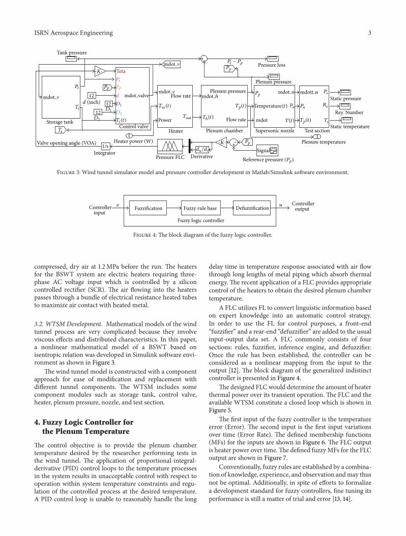
Figure 3: Wind tunnel simulator model and pressure controller development in Matlab/Simulink software environment.
Fuzzification DefuzzificationFuzzy rule base
Fuzzy logic controller
Controller input
Controller output
ue
Figure 4: The block diagram of the fuzzy logic controller.
compressed, dry air at 1.2MPa before the run. The heatersfor the BSWT system are electric heaters requiring three-phase AC voltage input which is controlled by a siliconcontrolled rectifier (SCR). The air flowing into the heaterspasses through a bundle of electrical resistance heated tubesto maximize air contact with heated metal.
3.2. WTSM Development. Mathematical models of the windtunnel process are very complicated because they involveviscous effects and distributed characteristics. In this paper,a nonlinear mathematical model of a BSWT based onisentropic relation was developed in Simulink software envi-ronment as shown in Figure 3.
The wind tunnel model is constructed with a componentapproach for ease of modification and replacement withdifferent tunnel components. The WTSM includes somecomponent modules such as storage tank, control valve,heater, plenum pressure, nozzle, and test section.
4. Fuzzy Logic Controller forthe Plenum Temperature
The control objective is to provide the plenum chambertemperature desired by the researcher performing tests inthe wind tunnel. The application of proportional-integral-derivative (PID) control loops to the temperature processesin the system results in unacceptable control with respect tooperation within system temperature constraints and regu-lation of the controlled process at the desired temperature.A PID control loop is unable to reasonably handle the long
delay time in temperature response associated with air flowthrough long lengths of metal piping which absorb thermalenergy. The recent application of a FLC provides appropriatecontrol of the heaters to obtain the desired plenum chambertemperature.
A FLC utilizes FL to convert linguistic information basedon expert knowledge into an automatic control strategy.In order to use the FL for control purposes, a front-end“fuzzifier” and a rear-end “defuzzifier” are added to the usualinput-output data set. A FLC commonly consists of foursections: rules, fuzzifier, inference engine, and defuzzifier.Once the rule has been established, the controller can beconsidered as a nonlinear mapping from the input to theoutput [12]. The block diagram of the generalized indistinctcontroller is presented in Figure 4.
The designed FLC would determine the amount of heaterthermal power over its transient operation. The FLC and theavailable WTSM constitute a closed loop which is shown inFigure 5.
The first input of the fuzzy controller is the temperatureerror (Error). The second input is the first input variationsover time (Error Rate). The defined membership functions(MFs) for the inputs are shown in Figure 6. The FLC outputis heater power over time.The defined fuzzyMFs for the FLCoutput are shown in Figure 7.
Conventionally, fuzzy rules are established by a combina-tion of knowledge, experience, and observation andmay thusnot be optimal. Additionally, in spite of efforts to formalizea development standard for fuzzy controllers, fine tuning itsperformance is still a matter of trial and error [13, 14].

4 ISRN Aerospace Engineering
DerivativeIntegrator
Temperature FLC
Actual plenum temperature
Wind tunnel simulator model
Reference temperature
Error
Heater power (W)Heater power
Plenum temperature
+−
Tp
du/dt
Derror
-K--K-
-K-1/s
Figure 5: Layout of the wind tunnel model and the temperature controller.
0
0.5
1
Error
MFs
(deg
) NeL NeM NeS Zero PoS PoM PoL
−1 −0.8 −0.6 −0.4 −0.2 0 0.2 0.4 0.6 0.8 1
(a)
0
0.5
1
Error Rate
NeL NeS Zero PoS PoL
−1 −0.8 −0.6 −0.4 −0.2 0 0.2 0.4 0.6 0.8 1
MFs
(deg
)
(b)
Figure 6: The defined membership functions for (a) Error and (b) Error Rate.
0
0.5
1
Heater power rate
NeL NeSNeM Zero PoS PoM PoL
−1 −0.8 −0.6 −0.4 −0.2 0 0.2 0.4 0.6 0.8 1
MFs
(deg
)
Figure 7: Heater power rate membership functions (FLC output).
Table 1: The fuzzy rules list.
Heater power rate Error RateNeL NeS Zero PoS PoL
ErrorNeL Zero NeM NeL NeL NeLNeM PoL Zero NeS NeL NeLNeS PoM PoS Zero NeM NeLZero PoM PoS Zero NeS NeMPoS PoL PoM Zero NeS NeMPoM PoL PoL PoS Zero NeLPoL PoL PoL PoL PoM Zero
The fuzzy rules list is presented in Table 1. For instance,one of the table entries is the equivalent of “if Error is Positive-Large and Error Rate is Zero then Heater Power Rate isPositive Large.”
The defuzzification process takes place after the gen-eration of the fuzzy control signals is completed usingthe inference mechanism. The resulting fuzzy set must beconverted to a quantity which would be sent to the processregulating valve as a control signal. In this part, the inferenceresults of all activated logic rules are synthesized into crispoutput for making a decision. In this research study, the logicAND has been implemented with the minimum operator,and the defuzzification method is based on bisector area.
01
01 Error Rate
Error
Hea
ter p
ower
rate
0
0.5
0.5
0
−0.5
−1
−1−0.5
Figure 8: Control surface output of the FLC.
1 1.5 2 2.5 3 3.5 40
2
4
6
8
10
Mach number
Plen
um p
ress
ure (
Pa)
Running phase
Starting phase
×105
Figure 9: The tests range for the proposed BSWT.
The variation of heater power rate versus the two controllerinputs is depicted in Figure 8.
By designing the controller, the influence of controllerparameters on wind tunnel should be examined in moredetail. So it would be essential to simulate the wind tunneland controller simultaneously.
ISRN Aerospace Engineering 5
0 20 40 60 80240
260
280
300
Time (s)
Tank
tem
pera
ture
(K)
Simulation runExperimental run
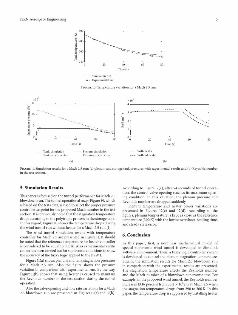
Figure 10: Temperature variation for a Mach 2.5 run.
0 20 40 60 800
5
10
15
Time (s)
Stag
natio
n pr
essu
re (P
a)
Tank-simulationTank-experimental
Plenum-simulationPlenum-experimental
×105
(a)
0 20 40 60 800
1
2
3
4
With heater
Time (s)
Without heater
×107
Re/L
(m−1)
(b)
Figure 11: Simulation results for a Mach 2.5 run: (a) plenum and storage tank pressures with experimental results and (b) Reynolds numberin the test section.
5. Simulation Results
This paper is focused on the tunnel performance forMach 2.5blowdown run.The tunnel operationalmap (Figure 9), whichis based on the tests data, is used to select the proper pressurecontroller setpoint for the proposed Mach number in the testsection. It is previously noted that the stagnation temperaturedrops according to the polytropic process in the storage tank.In this regard, Figure 10 shows the temperature drops duringthe wind tunnel run without heater for a Mach 2.5 run [1].
The wind tunnel simulation results with temperaturecontroller for Mach 2.5 are presented in Figure 11. It shouldbe noted that the reference temperature for heater controlleris considered to be equal to 300K. Also experimental verifi-cation has been carried out for supersonic conditions to showthe accuracy of the fuzzy logic applied to the BSWT.
Figure 11(a) shows plenum and tank stagnation pressuresfor a Mach 2.5 run. Also the figure shows the pressurevariation in comparison with experimental run. By the way,Figure 11(b) shows that using heater is caused to maintainthe Reynolds number in the test section during the tunneloperation.
Also the valve opening and flow rate variations for aMach2.5 blowdown run are presented in Figures 12(a) and 12(b).
According to Figure 12(a), after 54 seconds of tunnel opera-tion, the control valve opening reaches its maximum open-ing condition. In this situation, the plenum pressure andReynolds number are dropped suddenly.
Plenum temperature and heater power variations arepresented in Figures 12(c) and 12(d). According to thefigures, plenum temperature is kept as close as the referencetemperature (300K) with the lowest overshoot, settling time,and steady state error.
6. Conclusion
In this paper, first, a nonlinear mathematical model ofspecial supersonic wind tunnel is developed in Simulinksoftware environment. Then, a fuzzy logic controller systemis developed to control the plenum stagnation temperature.Finally, the simulation results for Mach 2.5 blowdown runin comparison with the experimental results are presented.The stagnation temperature affects the Reynolds numberand the Mach number of a blowdown supersonic test. Forexample, in the proposed wind tunnel, the Reynolds numberincreases 13.16 percent from 30.8 × 10⁶/m at Mach 2.5 whenthe stagnation temperature drops from 290 to 260K. In thispaper, the temperature drop is suppressed by installing heater

6 ISRN Aerospace Engineering
0 20 40 60 800
50
100
Time (s)
VOA
(deg
)
Bray control valve (12 inches)
(a)
Time (s)0 20 40 60 80
0
10
20
30
Flow
rate
(kg/
s)
(b)
Time (s)0 2 4 6 8 10
280
290
300
Plen
um te
mpe
ratu
re (K
)
Plenum temperatureReference temperature
(c)
Time (s)0 20 40 60 80
0
200
400
600
Pow
er (k
w)
(d)
Figure 12: Simulation results for a Mach 2.5 run: (a) valve opening angle (VOA) function, (b) valve flow rate, (c) plenum stagnationtemperature, and (d) heater power variation during the tunnel run.
and temperature controller upstream of the plenum chamberto maintain a constant Reynolds number with keeping thestagnation pressure constant. In this way, the Error in theheater performance during the run is minimized with thecontrol program for the wind tunnel facility characteristics.The new intelligent control system leads to a control responsewith the lowest overshoot, settling time, and steady stateerror.
Conflict of Interests
The authors declare that there is no conflict of interestsregarding the publication of this paper.
References
[1] A. Nazarian Shahrbabaki, M. Bazazzadeh, A. Shahriari, andM. D. Manshadi, “Intelligent controller design for a blowdownsupersonicwind tunnel,” SERSC International Journal of Controland Automation, vol. 7, pp. 409–426, 2014.
[2] F. K. Lu, D. R. Wilson, and J. Matsumoto, “Rapid valve open-ing technique for supersonic blowdown tunnel,” ExperimentalThermal and Fluid Science, vol. 33, no. 3, pp. 551–554, 2009.
[3] C. R. Nott, S. M. Olcmen, D. R. Lewis, and K. Williams,“Supersonic, variable-throat, blow-down wind tunnel controlusing genetic algorithms, neural networks, and gain scheduledPID,” Applied Intelligence, vol. 29, no. 1, pp. 79–89, 2008.
[4] S. H. Rajani, M. K. Bindu, and N. Usha, “Stability analysisand temperature effect on the settling chamber pressure of ahypersonic wind tunnel,” in Proceedings of the IEEE Interna-tional Conference on Computational Intelligence and ComputingResearch (ICCIC ’12), 2012.
[5] D.-S. Hwang and P.-L. Hsu, “A robust controller design forsupersonic intermittent blowdown-type windtunnels,” Aero-nautical Journal, vol. 102, no. 1013, pp. 161–169, 1998.
[6] L. A. Zadeh, G. J. Klir, and B. Yuan, Fuzzy Sets, Fuzzy Logic,Fuzzy Systems, World Scientific Publishing, Hackensack, NJ,USA, 1996.
[7] P. J. King and E. H. Mamdani, “The application of fuzzy controlsystems to industrial processes,” Automatica, vol. 13, no. 3, pp.235–242, 1977.
[8] A. Pope and K. L. Goin, High-Speed Wind Tunnel Testing, JohnWiley & Sons, New York, NY, USA, 1965.
[9] L. Biagioni, F. Scortecci, and F. Paganucci, “Development ofpulsed arc heater for small hypersonic high-enthalpy windtunnel,” Journal of Spacecraft and Rockets, vol. 36, no. 5, pp. 704–710, 1999.
[10] Fisher Controls International, Control Valve Handbook, FisherInternational Company, Marshalltown, Ia, USA, 2nd edition,2005.
[11] L. Driskell, Control-Valve Selection and Sizing, Instrument Soci-ety of America, Research Triangle Park, NC, USA, 1st edition,1983.
[12] J. H. Lilly, Fuzzy Control and Identification, John Wiley & Sons,New York, NY, USA, 2010.
[13] D. Driankov, H. Hellendoorn, and M. Reinfrank, An Introduc-tion to Fuzzy Control, Springer, Berlin, Germany, 2nd edition,1996.
[14] K.M. Passino and S. Yurkovich,FuzzyControl, Addison-Wesley,San Francisco, Calif, USA, 1998.

Submit your manuscripts athttp://www.hindawi.com
VLSI Design
Hindawi Publishing Corporationhttp://www.hindawi.com Volume 2014
International Journal of
RotatingMachinery
Hindawi Publishing Corporationhttp://www.hindawi.com Volume 2014
Hindawi Publishing Corporation http://www.hindawi.com
Journal ofEngineeringVolume 2014
Hindawi Publishing Corporationhttp://www.hindawi.com Volume 2014
Shock and Vibration
Hindawi Publishing Corporationhttp://www.hindawi.com Volume 2014
Mechanical Engineering
Advances in
Hindawi Publishing Corporationhttp://www.hindawi.com Volume 2014
Civil EngineeringAdvances in
Acoustics and VibrationAdvances in
Hindawi Publishing Corporationhttp://www.hindawi.com Volume 2014
Hindawi Publishing Corporationhttp://www.hindawi.com Volume 2014
Electrical and Computer Engineering
Journal of
Hindawi Publishing Corporationhttp://www.hindawi.com Volume 2014
Distributed Sensor Networks
International Journal of
The Scientific World JournalHindawi Publishing Corporation http://www.hindawi.com Volume 2014
SensorsJournal of
Hindawi Publishing Corporationhttp://www.hindawi.com Volume 2014
Modelling & Simulation in EngineeringHindawi Publishing Corporation http://www.hindawi.com Volume 2014
Hindawi Publishing Corporationhttp://www.hindawi.com Volume 2014
Active and Passive Electronic Components
Hindawi Publishing Corporationhttp://www.hindawi.com Volume 2014
Chemical EngineeringInternational Journal of
Control Scienceand Engineering
Journal of
Hindawi Publishing Corporationhttp://www.hindawi.com Volume 2014
Antennas andPropagation
International Journal of
Hindawi Publishing Corporationhttp://www.hindawi.com Volume 2014
Hindawi Publishing Corporationhttp://www.hindawi.com Volume 2014
Navigation and Observation
International Journal of
Advances inOptoElectronics
Hindawi Publishing Corporation http://www.hindawi.com
Volume 2014
RoboticsJournal of
Hindawi Publishing Corporationhttp://www.hindawi.com Volume 2014