enlarging canopen applications with ethernet powerlink · enlarging canopen applications with...
TRANSCRIPT
iCC 2006 CAN in Automation
04-6
Enlarging CANopen applications with ETHERNET Powerlink
Christian Schlegel, IXXAT Automation GmbH
During the last 10 years, CANopen became one of the most popular higher layer protocols for CAN-based networks. Compared with other higher layer protocols, the essential benefits of CANopen are its simplicity and flexibility which enables its use in a wide range of application areas. The versatility of CANopen is also reflected by the large number of available device, interface and application profiles. However, due to the increasing requirements of enlarging applications and systems, the maximum extension of CAN systems and the available data band width become serious limitations for the usage of CANopen in these applications. One of the most promising approaches to overcome these limitations is given by ETHERNET Powerlink, which conserves all the well appreciated CANopen mechanisms and profiles. Ethernet Powerlink is based on standard Ethernet but provides very high communication bandwith and hard real-time features. From the application point of view, there is no difference between CANopen and ETHERNET Powerlink concerning data representation, the object dictionary and the provided services. Therefore a migration becomes easy. Using gateways, CANopen and ETHERNET Powerlink systems can be interconnected smoothly.
1 CANopen systems and applications today
More than 10 years ago, when the first CANopen specification was developed and released, CANopen was a milestone towards open and interoperable CAN-based communication systems. At that time, CANopen was mainly intended to be used in classical industrial automation systems. This was also reflected by the first device profiles which were developed, like DS401 for I/Os, DS402 for motion and drives or DS405 for PLCs. However, due to its simplicity and flexibility, CANopen became more and more attractive in other application areas. Today, there are device and application profiles under development or already available for building related applications like door control or lifts, for ships, trains, municipal vehicles or railways as well as for medical applications. Besides these standardized profiles, CANopen is also used in a wide range of proprietary systems and applications. The flexibility of CANopen is manifested in the uniform method of describing a device functionality and its data by means of the object dictionary and on the powerful but simple to use PDO and SDO protocols.
Nevertheless, since CANopen is based on CAN, there are some limitations which limit the use of CANopen for certain applications. The limitations are: • Maximum baud rate of 1 Mbit/s:
This limitation is a direct result of the bandwith available for data to be transmitted and is a limit especially for applications requiring cyclic and synchronous transfer of data with low cycle times (e.g motion control applications) and for applications requiring the transfer of larger data packets (e.g. measurement appli-cations).
• Maximum system extension (length of CAN line): Due to the arbitration principle used in CAN, this limitation is a direct result of the selected baud rate. Systems running at 1 Mbit/s or 500 kbit/s providing a considerable high band width can have a maximum length of only 25m (80ft.) or 100m (320ft.) which is too short for certain applications (e.g building related applications like lift or control applications for larger systems or machines). Systems running at 125 kbit/s can have a maximum length of 500m (1600ft.), however, the bandwith becomes considerably low for certain

iCC 2006 CAN in Automation
04-7
applications (e.g. control applications or measurement applications).
There are already existing solutions available that address the limitation of the maximum system expansion. For example, the use of repeaters allow different topologies than the line topology (with more or less no disadvantage to the CANopen system) and the use of CAN to CAN bridges which in principle allow to have n times the maximum length of the CAN line in one CANopen system (with the disadvantages that the latency times increase considerably for the transmission of one CAN message from one end to the other end of the system and that the CAN principle of a guaranteed data consistency within one CAN system is not valid anymore). In addition to these two simple possibilities for extending the maximum extension of a CANopen system, there is the new interface profile DS400 “Multilevel Networking” [1]. This specification defines a CANopen / CANopen gateway to be used for interconnecting several CANopen systems and for providing a configurable exchange of PDO data within these systems and also the possibility of SDO access from one device to a device in another CANopen network interconnected by the gateway. As the trend towards larger and more complex applications and systems leads to a system design based not only on one system but on sub-systems interconnected by gateways or specific application programs acting also as a gateway, the existence of the DS400 specification reflects this trend. However, thinking of an application based on several sub-systems interconnected by a backbone system for exchanging data between the sub-systems or for collecting data via the backbone, a higher bandwidth is required on this backbone system (possibly also in relation with a larger extension of the backbone). Therefore it would be beneficial to have another communication system that is able to provide high bandwidth and larger system extensions with the same operating principle as CANopen. Thinking of a communication system with the stated requirements, Ethernet comes rapidly to mind. Ethernet is fast (100 Mbit/s
or even 1 Gbit/s) allows large system extensions (virtually unlimited when using switches), is a proven technology and is already supported directly by nearly all 32-bit CPU types. However, main drawbacks for why standard Ethernet cannot be used are: no guaranteed band-width and no guaranteed latency times (which also means no real-time capability due to the collisions on Ethernet and due to the switch technology) and the lack of an appropriate application layer with the necessary protocols. 2 ETHERNET Powerlink: Upgrading CANopen to ethernet
Originally, an initial version of ETHERNET Powerlink (EPL) was developed by B&R in 2001 and opened to other companies at the Hannover Fair in 2002. When the EPSG (ETHERNET Powerlink Standardization Group [2]) was established, the development of the EPL specification was started and finished end of 2003. With the EPL specification [3], an application layer was specified providing the CANopen mechanisms like object dictionary, PDO and SDO and NMT with ETHERNET Powerlink. ETHERNET Powerlink is based on Fast Ethernet IEEE802.3. In order to come around of the collisions usually occurring in Ethernet systems, EPL uses a master / slave approach for granting the devices access to the media (Ethernet). A typical EPL system is shown in figure 1. A brief introduction to EPL can be found on [4].
Figure 1: EPL system architecture (logical view) All EPL devices must reside in a separate real-time Ethernet segment. No other
iCC 2006 CAN in Automation
04-8
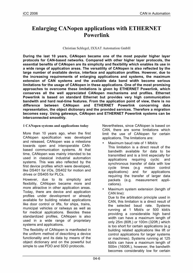
Ethernet based devices except EPL devices are allowed in this segment in order to avoid collisions. There is one device acting as “Managing Node” (Manager, MN), the other devices (up to 239) are “Controlled Nodes” (CN). The devices are interconnected using hubs. As no collisions can occur, the number of hubs in a line is not limited. So in principle the maximum length of an EPL system is also not limited. Only the maximum distance between two hubs is limited by the line drivers to approximately 100m (320ft.) The way the devices communicate in an EPL system is based on a communication cycle, which is split into a synchronous period and an asynchronous period. In the synchronous period, the time-critical process data is transmitted cyclically. The asynchronous period is used to transmit any other kind of non time-critical data like network management data and services, parameter data or TCP/IP frames. Figure 2 shows the structure of an EPL communication cycle. A communication cycle starts with the SoC message (Start of Cycle). With this message all devices in the system can be synchronized with a jitter below 1µs. In the synchronous period, the Manager sends a unicast poll request message to each Controller and each Controller answers with a poll response message. Poll request as well as poll response messages contain the process data. The poll response messages are transmitted with multicast Ethernet addresses, so they can be received by any other device in the segment. At the end of the synchronous period, the Manager sends also a multicast poll response message in order to broadcast its own process data. In addition, the Manager can also send dedicated process data to an individual Controlled Node within the poll request message. The start of the asynchronous period is indicated by the SoA (Start of Asynchronous) message. With this message, the Manager requests identification data or status information from a certain Controlled Node or allows the Controlled Node to send an individual frame, which can either be an EPL frame (e.g. for parameter transfer) or an IP
frame. The right to send data in the asynchronous slot is granted by the Manager in a non-deterministic way upon request from the respective Controlled Node.
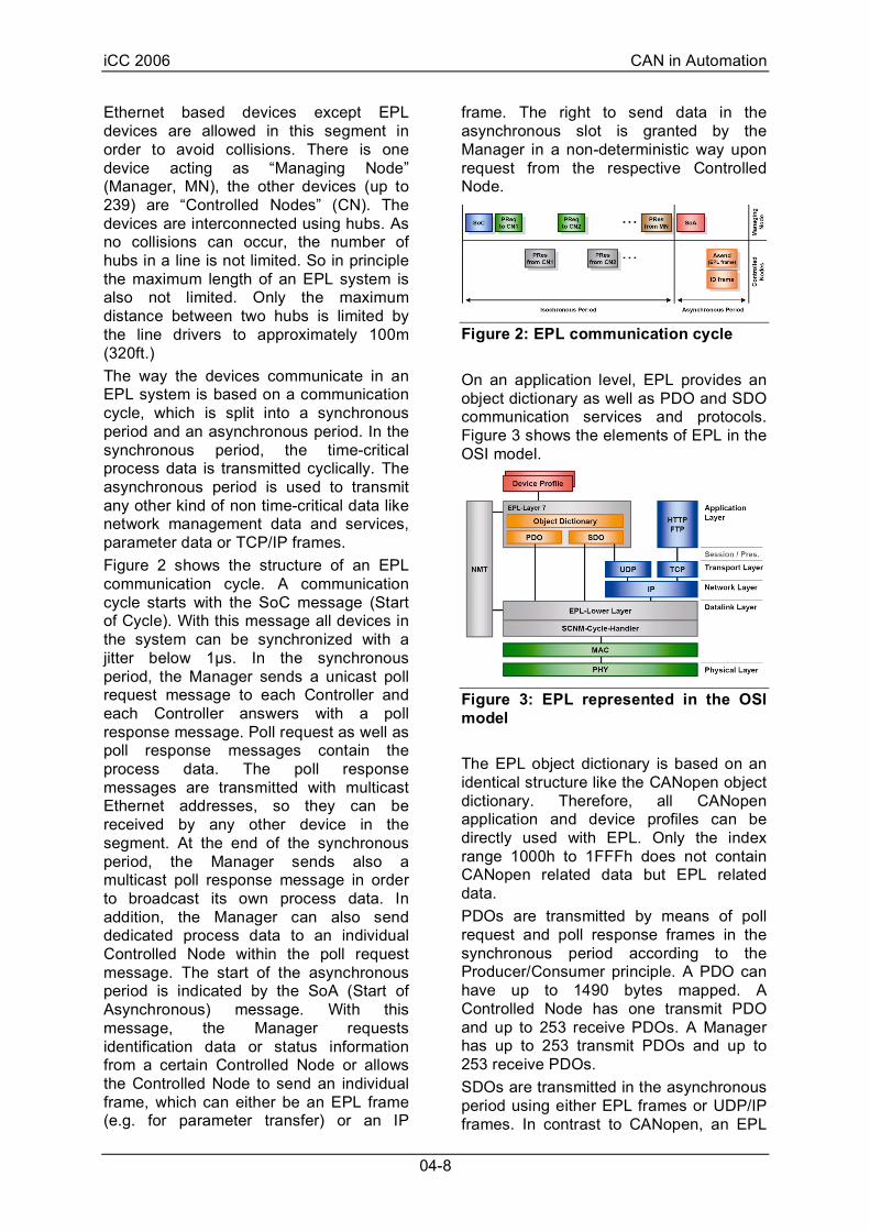
Figure 2: EPL communication cycle On an application level, EPL provides an object dictionary as well as PDO and SDO communication services and protocols. Figure 3 shows the elements of EPL in the OSI model.
Figure 3: EPL represented in the OSI model The EPL object dictionary is based on an identical structure like the CANopen object dictionary. Therefore, all CANopen application and device profiles can be directly used with EPL. Only the index range 1000h to 1FFFh does not contain CANopen related data but EPL related data. PDOs are transmitted by means of poll request and poll response frames in the synchronous period according to the Producer/Consumer principle. A PDO can have up to 1490 bytes mapped. A Controlled Node has one transmit PDO and up to 253 receive PDOs. A Manager has up to 253 transmit PDOs and up to 253 receive PDOs. SDOs are transmitted in the asynchronous period using either EPL frames or UDP/IP frames. In contrast to CANopen, an EPL

iCC 2006 CAN in Automation
04-9
device can access any other EPL device by an SDO. With the UDP/IP based SDO protocol, it is also possible to route the SDO via standard Ethernet (Internet) using a special Router device. This allows to access an EPL device with a non-EPL device like a standard PC. Since on the application level, the object dictionary mechanisms are identical it becomes fairly easy to exchange data between CANopen and EPL. Moreover, from the point of view of an application, there is no difference whether the application runs on a CANopen stack or on an EPL stack. A corresponding virtual software architecture is shown in figure 4.
Figure 4: Virtual EPL/CANopen software architecture 3 New system architectures with CANopen and ETHERNET Powerlink
One solution circumvents the limitations of CANopen would be switching completely to EPL. However, for many systems this would be like the tail wagging the dog since the EPL technology is more expensive than the CANopen technology (e.g. cabling costs, hardware costs, system integration costs). Instead of converting a system completely from CANopen to EPL, it often makes sense to build a new system structure using several subsystems. With EPL and CANopen, basically the following two system architectures are possible:
• EPL as main or backbone system with CANopen sub-systems This system concept is shown in figure 5. In this system architecture, sub-functions of the whole system are implemented using CANopen sub-systems and EPL as the backbone or main control system. This system concept allows the fast distribution of process data between the CANopen sub-systems, the centralized handling of control data and logging of process data for all CANopen sub-systems. It also allows longer extensions between the CANopen sub-systems and thus a longer extension of the total system.
Figure 5: System architecture with EPL as main system and CANopen as sub-systems • CANopen as main or backbone system
with EPL sub-systems This system concept is shown in figure 6. Here, sub-functions of the system are implemented using EPL. This would apply mainly for sub-functions which require very short cycle times (like high-performance motion sub-systems) or high bandwidth. A use case for this system concept is, for example, a measurement sub-system where the measurements are processed and stored in the sub-system and only calculated results and control data is exchanged with the CANopen system.

iCC 2006 CAN in Automation
04-10
Figure 6: System architecture with CANopen as main system and EPL as sub-systems The main functionality of the gateway is to forward process data transmitted by PDOs from one system to the other system. Since not all process data which is transmitted in one system is important for the other system, it is necessary that the gateway is able to configure which process data is exchanged between the two systems. In addition to the exchange of process data between CANopen and EPL systems, the possibility of accessing devices in other systems across system borders by SDO is required (remote SDO access). Since the SDO access is a client-server based mechanism, a device addressing method becomes necessary that is able to address a certain device in a certain sub-system (or network). For CANopen, a network-ID was already introduced with DS400 [1]. For EPL, the IP addresses in combination with the NAT mechanism (Network Address Translation) already provide this possibility. Finally, the forwarding of error messages from a sub-system into the main / backbone system and also the control of the network management of the sub-system from the main / backbone system is a further requirement. All the above mentioned mechanisms have to be provided by an EPL / CANopen gateway. 4 ETHERNET Powerlink / CANopen gateway
A typical EPL / CANopen gateway can be implemented using a standard CPU with integrated CAN controller and Ethernet
MAC. It is recommended that a 32-bit CPU with a mid range performance is used in order to achieve acceptable latency and response times. The basic software architecture of a gateway is shown in figure 7. Basically a CANopen stack and an EPL stack have to be implemented. In between the stacks, a system control task is responsible for handling remote SDO access and forwarding of NMT services and error information.
Figure 7: Software architecture of an ETHERNET Powerlink / CANopen gateway For the exchange of process data, which is transmitted on both sides inside PDOs, a process image is implemented between both stacks based on a shared memory. Using the network variables approach specified in CiA DS302 [5] and CiA DS405 [6], process data received on one communication interface by RXPDOs can be flexibly mapped into TXPDOs on the other communication interface. Within the index range of A000h to A8FFh, each object entry with a given index / sub-index references a certain location in the input or output process image by defining a data type and an address offset. Table 1 gives an overview on object ranges and data types. Table 2 shows some examples concerning the relation of object index/sub-index, data type and location in the process image. E.g., the object A101h/10h references a location inside the input process image of data type UNSIGNED16 at address offset 538. The object A680h/02h references a location inside the output process image of data type UNSIGNED32 at address offset 4.
Table 1

iCC 2006 CAN in Automation
04-11
Index range Data type Direction A000h – A03Fh INTEGER8 input A040h – A07Fh UNSIGNED8 input … … … A100h – A13Fh UNSIGNED16 input … … … A200h – A2FFh UNSIGEND32 input … … … A480h – A4BFh INTEGER8 output A4C0h – A4FFh UNSIGNED8 output … … … A580h – A5BFh UNSIGNED16 output … … … A680h – A6BFh UNSIGEND32 output … … …
Table 2
Index/ Subindex
Data type Dir Adress offset
A000h/01h INTEGER8 input 0 A001h/10h INTEGER8 input 270 A040h/01h UNSIGNED8 input 0 A100h/01h UNSIGNED16 input 0 A100h/02h UNSIGNED16 input 2 A101h/10h UNSIGNED16 input 538 A680h/01h UNSIGNED32 output 0 A680h/02h UNSIGNED32 output 4 A681h/10h UNSIGNED32 output 1076
Figure 8 shows the correlation between the index ranges and the process image in the shared memory for both communica-tion interfaces.
Figure 8: Exchange of process data via the process image in the shared memory In order to handle remote SDO access services, the existing SDO protocols need to be extended. For CANopen, an extension was already introduced in DS400 [1] by means of the SDO Network Indication protocol.
On the EPL side, an extension of the SDO protocol or SDO services is required to consider the extension of the CANopen SDO protocols. Therefore, an EPL / CANopen gateway needs to distinguish two scenarios: (a) the remote device which shall be accessed by a remote SDO access is located in the same EPL network or in another remote EPL network which can be accessed without a CANopen network in between or (b) the remote device is located in another network which can only be accessed via a CANopen network. In scenario (a), the EPL / CANopen gateway answers the CANopen SDO network indication request with a response and waits for the consecutive SDO access request. This request is then transferred to the new EPL SDO Remote Read by Index or SDO Remote Write by Index service. These services use the parameters net_id and node_id for referencing the remote device. In scenario (b), the CANopen SDO network indication protocol needs to be routed over the EPL network(s). Therefore, a new EPL SDO service SDO Network Indication is introduced. This service works in the same way as the CANopen service which means the gateway transmits the EPL SDO Network Indication request to the next EPL / CANopen gateway and waits for the response. After receiving the response, it also transmits the SDO Network Indication response on its CANopen interface. The EPL / CANopen gateway requires a translation table which contains the information whether a certain remote network can be accessed directly (only via EPL networks) or that there are CANopen networks in between. The translation table can be configured via object dictionary entries. A CANopen Master or EPL Manager can be requested to send NMT services using object 1F82h as defined in DS302 [5] for CANopen and 1F9Fh as defined in [3] for EPL. Errors occurred and signaled in one network by means of an emergency message (CANopen) or via the error signaling mechanism (EPL) can be forwarded by the gateway to the other

iCC 2006 CAN in Automation
04-12
network by using a dedicated error code indicating that the error transmitted occurred in another network. In the additional information field of the error message, the information about the error source can be described by network ID, node ID and original error code. Additional object entries can be provided by the gateway that enable the configuration which errors shall be forwarded on the other network. An EPL / CANopen gateway can be implemented within a small device. Figure 9 shows an example for an existing gateway based on the Freescale Coldfire MCF5235 in a housing for DIN rails. Figure 10 gives an overview on the implemented hardware architecture.
Figure 9: ETHERNET Powerlink / CANopen gateway
Figure 10: Hardware architecture of an ETHERNET Powerlink / CANopen gateway 5 Conclusion
ETHERNET Powerlink with its CANopen conforming application layer is the ideal complement to CANopen. Based on Ethernet, it combines all the benefits of a proven and world-wide available technol-ogy like high band-width for data transfers, standardized internet protocols, long system extensions with real-time capa-bilities within the microsecond range and the state-of-the-art CANopen mecha-nisms. From the point of view of an application there is no difference whether the application runs on top of a CANopen stack or on top of an EPL stack. Existing applications can be transferred from CANopen to EPL without modifications to the application. The existence of EPL / CANopen gate-ways enables system designs with EPL and CANopen networks using the most appropriate communication solution for a sub-system depending on the application. Moreover, existing EPL / EPL routers and CANopen / CANopen gateways allow the design of a wide variety of mixed-system architectures enabling CANopen and EPL approaching new application areas. References
[1] CiA DS401 Multilevel Networking Version 1.0 CAN in Automation
[2] EPSG ETHERNET Powerlink Standardization Group http:///www.epsg.org
[3] ETHERNET Powerlink V2 Communication Profile Specification Draft Standard Version 1.0.0 EPSG
[4] http://www.ixxat.de/elp_article_en.html [5] CiA DS302 Framework for CANopen
Managers and Programmable CANopen Devices Version 3.3.0 CAN in Automation
[6] CiA DS405 Interface and Device Profile for IEC61131-3 Programmable Devices Version 2.0 CAN in Automation