~entered - hwbdocuments.env.nm.gov national labs/2014-09-10 mwl... · the new mexico environment...
TRANSCRIPT

N.11inri>Jl Nuclear Security Ar.fmi11islr;1fion
Mr. John E. Kieling Chief
~ENTERED Department of Energy
National Nuclear Security Administration Sandia Field Office
P. 0. Box 5400 Albuquerque, NM 87185
SEP 1 0 2014 CERTIFIED MAIL-RETURN RECEIPT REQUESTED
Permits Management Program Hazardous Waste Bureau New Mexico Environment Department 2905 Rodeo Park Drive East, Bldg. 1 Santa Fe, NM 87505
SEP 1 6 ~1,;1
Subject: Department of Energy/National Nuclear Security Administration Sandia National Laboratories Environmental Restoration Operations Installation of Three FLUTe™
Soil-Vapor Monitoring Wells (MWL-SV03, MWL-SV04, and MWL-SV05) at the Mixed Waste Landfill.
Dear Mr. Kieling:
The Department of Energy/National Nuclear Security Administration and Sandia Corporation (Sandia) are submitting the final report Installation of Three FLUTe™ Soil-Vapor Monitoring Wells (MWL-SV03, MWL-SV04, and MWL-SV05) at the Mixed Waste Landfill. Submittal of this report to the New Mexico Environment Department (NMED), Hazardous Waste Bureau (HWB) is required by the NMED-approved MWL Soil-Vapor Well Installation Plan, dated January 2014, and completes the deployment of all monitoring systems required by the Mixed Waste Landfill Long-Term Monitoring and Maintenance Plan (L TMMP) in accordance with the NMED L TMMP approval letter dated January 8, 2014 ..
The enclosed report documents the field activities for the three soil-vapor monitoring wells. The first semiannual soil-vapor monitoring event will be conducted in September 2014 and will be reported in the next MWL Annual Long-Term Monitoring and Maintenance Report in accordance with L TMMP requirements (submittal to NMED in June 2015).
If you have questions, please contact me at (505) 284-6668 or John Weckerle of my staff at (505) 845-6026.
me Assistant Manager for Engineering
Enclosure
cc: See Page 2
;__Q I
au

Mr. John E. Kieling
cc w/enclosure (Certified Mail): William Moats NMED-HWB 5500 San Antonio Dr., NE Albuquerque, NM 87109
Laurie King EPA, Region 6 1445 Ross Ave., Ste. 1200 Dallas, TX 75202
cc w/enclosure: David Cobrain, NMED-HWB 2905 Rodeo Park Drive East, Bldg. 1 Santa Fe, NM 87505
Thomas Skibitski NMED-OB, MS-1396 SNL ES&H Records Center SNL/NM, MS-0718
Zimmerman Library University of New Mexico MSC05 3020 1 University of New Mexico Albuquerque, NM 87101-0001
cc w/o enclosure: Amy Blumberg, SNL/NM, MS-0141 John Cochran, SNL/NM, MS-0719 Peter Davies SNL/NM, MS-0721 David Miller, SNL/NM, MS-0718 Michael Mitchell, SNL/NM, MS-0718 Pamela Puissant, SNL/NM, MS-0729 Sandra Sedillo, SNL/NM, MS-0727 John Weckerle, SFO/ENG, MS-0184 Joe Estrada, SFO/ENG, MS-0184 Cynthia Wimberly, SFO/Legal, MS-0184 14-680-591993
-2- SEP 1 0 20111

Sandia National Laboratories, New Mexico Environmental Restoration Operations
Installation of Three FLUTe™ Soil-Vapor
Monitoring Wells (MWL-SV03, MWL-SV04, and MWL-SV05) at the Mixed Waste Landfill
September 2014
United States Department of Energy Sandia Field Office
Sandia National Laboratories is a multi-program laboratory managed and operated by Sandia Corporation, a wholly owned subsidiary of Lockheed Martin Corporation, for the U.S. Department of Energy’s
National Nuclear Security Administration under contract DE-AC04-94AL85000.

MWL FLUTe Installation Report_September 2014.docx 146239.02002000 08/20/14 3:05 PM i
TABLE OF CONTENTS LIST OF FIGURES .................................................................................................................... iii LIST OF TABLES ........................................................................................................................ v LIST OF APPENDICES ............................................................................................................ vii ACRONYMS AND ABBREVIATIONS ........................................................................................ ix 1.0 INTRODUCTION ..........................................................................................................1-1
1.1 Report Objective ...............................................................................................1-1 1.2 Regulatory Criteria ............................................................................................1-1 1.3 Report Organization ..........................................................................................1-4
2.0 SOIL-VAPOR MONITORING WELL INSTALLATION ...................................................2-1
2.1 Equipment Decontamination and Environmentally Sensitive Practices .............2-1 2.2 Drilling Activities ................................................................................................2-1 2.3 Well Installation Process ...................................................................................2-4 2.4 FLUTe™ Well Design .......................................................................................2-6 2.5 Surveying ..........................................................................................................2-6
3.0 VARIANCES FROM WORK PLAN ...............................................................................3-1 4.0 REFERENCES .............................................................................................................4-1

MWL FLUTe Installation Report_September 2014.docx 146239.02002000 08/20/14 3:05 PM ii
This page intentionally left blank.

MWL FLUTe Installation Report_September 2014.docx 146239.02002000 08/20/14 3:05 PM iii
LIST OF FIGURES
Figure
1-1 Location of the Mixed Waste Landfill at Sandia National Laboratories,
New Mexico and Kirtland Air Force Base ..........................................................1-2 1-2 Location Map of Monitoring Wells at the Mixed Waste Landfill. .........................1-3 2-1 GEFCO Speedstar 50K-CH Drill Rig at Soil-Vapor Monitoring Well
MWL-SV03 along the Western Perimeter Fence of the MWL ............................2-2

MWL FLUTe Installation Report_September 2014.docx 146239.02002000 08/20/14 3:05 PM iv
This page intentionally left blank.

MWL FLUTe Installation Report_September 2014.docx 146239.02002000 08/20/14 3:05 PM v
LIST OF TABLES
Table
2-1 Chronology of Drilling and Well Installation Events at the MWL ........................2-3 2-2 Summary of Construction Details for the FLUTe™ Soil-Vapor Monitoring
Wells at the MWL ..............................................................................................2-7

MWL FLUTe Installation Report_September 2014.docx 146239.02002000 08/20/14 3:05 PM vi
This page intentionally left blank.

MWL FLUTe Installation Report_September 2014.docx 146239.02002000 08/20/14 3:05 PM vii
LIST OF APPENDICES
Appendix A Lithologic Logs for Soil-Vapor Monitoring Wells MWL-SV03, MWL-SV04, and
MWL-SV05 B Well Construction Data Sheets for Soil-Vapor Monitoring Wells MWL-SV03,
MWL-SV04, and MWL-SV05 C Well Construction Diagrams for Soil-Vapor Monitoring Wells MWL-SV03,
MWL-SV04, and MWL-SV05 D Well Database Summary Forms for Soil-Vapor Monitoring Wells MWL-SV03,
MWL-SV04, and MWL-SV05 E Lithologic Log for Borehole MWL-BH16 F Photographs of Drilling and Well Installation Activities at the MWL

MWL FLUTe Installation Report_September 2014.docx 146239.02002000 08/20/14 3:05 PM viii
This page intentionally left blank.

MWL FLUTe Installation Report_September 2014.docx 146239.02002000 08/20/14 3:05 PM ix
ACRONYMS AND ABBREVIATIONS ARCH air rotary casing hammer bgs below ground surface CSS Colorado Silica Sand DOE U.S. Department of Energy ER Environmental Restoration FLUTe™ Flexible Liner Underground Technology, Ltd.™ ft foot or feet HWB Hazardous Waste Bureau LTMMP Long Term Monitoring and Maintenance Plan MWL Mixed Waste Landfill mil thousandth of an inch NMED New Mexico Environment Department NMOSE New Mexico Office of the State Engineer OD outside diameter PVC polyvinyl chloride RCRA Resource Conservation and Recovery Act Sandia Sandia Corporation SNL/NM Sandia National Laboratories, New Mexico SWMU Solid Waste Management Unit TA Technical Area TD total depth the Order Compliance Order on Consent YJ Yellow Jacket Drilling Services, Inc.

MWL FLUTe Installation Report_September 2014.docx 146239.02002000 08/20/14 3:05 PM x
This page intentionally left blank.

MWL FLUTe Installation Report_September 2014.docx 146239.02002000 08/20/14 3:05 PM 1-1
1.0 INTRODUCTION
1.1 Report Objective This installation report describes the May through July 2014 drilling activities performed for the installation of three multi-port soil-vapor monitoring wells (MWL-SV03, MWL-SV04, and MWL-SV05) at the Mixed Waste Landfill (MWL), which is located at Sandia National Laboratories, New Mexico (SNL/NM). SNL/NM is managed and operated by Sandia Corporation (Sandia), a wholly owned subsidiary of Lockheed Martin Corporation, for the U.S. Department of Energy (DOE)/National Nuclear Security Administration. The MWL is designated as Solid Waste Management Unit (SWMU) 76 and is located in Technical Area (TA) III (Figure 1-1). The locations of the three soil-vapor monitoring wells (MWL-SV03, MWL-SV04, and MWL-SV05) are shown in Figure 1-2.
1.2 Regulatory Criteria The New Mexico Environment Department (NMED) Hazardous Waste Bureau (HWB) provides regulatory oversight of the SNL/NM Environmental Restoration (ER) efforts and implements and enforces regulations mandated by the Resource Conservation and Recovery Act (RCRA). All ER Operations SWMUs and Areas of Concern are listed in Module IV of the SNL/NM RCRA Part B Operating Permit, Special Conditions Pursuant to the 1984 Hazardous and Solid Waste Amendments to RCRA for Sandia National Laboratories (NMED 1993). In April 2004, a Compliance Order on Consent (the Order) (NMED April 2004) became effective between the NMED, DOE, and Sandia, which specifically identified SWMU 76 (the MWL) as requiring corrective action. The MWL is also subject to corrective action under 20.4.1.500 New Mexico Administrative Code incorporating 40 Code of Federal Regulations 264.101. The NMED HWB is the lead regulatory agency and oversees corrective action at the MWL under the provisions of the Order (NMED April 2004) issued pursuant to the New Mexico Hazardous Waste Act and addresses requirements concerning nitrate and perchlorate pursuant to the New Mexico Solid Waste Act. The NMED Final Order on the MWL (Curry May 2005) and the related Class 3 Permit Modification require an MWL long-term monitoring and maintenance plan (LTMMP) to address monitoring, inspection, maintenance, physical and institutional controls, and reporting for the MWL following remedy implementation. The MWL LTMMP (SNL/NM March 2012) was approved by NMED on January 8, 2014 (Blaine January 2014) and required the installation of three soil-vapor monitoring wells to complete the LTMMP monitoring systems. The Soil-Vapor Monitoring Well Installation Work Plan (the Work Plan; SNL/NM January 2014) was approved by NMED in February 2014 (Blaine February 2014). All associated drilling and installation field work was performed in accordance with the NMED-approved Work Plan. Variances related to difficulties encountered at the original MWL-SV03/BH16 location are discussed in Sections 2.2 and 3.0.

MWL FLUTe Installation Report_September 2014.docx 146239.02002000 08/20/14 3:05 PM 1-2
Figure 1-1
Location of the Mixed Waste Landfill at Sandia National Laboratories, New Mexico and Kirtland Air Force Base

MWL FLUTe Installation Report_September 2014.docx 146239.02002000 08/20/14 3:05 PM 1-3
Figure 1-2 Location Map of Monitoring Wells at the Mixed Waste Landfill

MWL FLUTe Installation Report_September 2014.docx 146239.02002000 08/20/14 3:05 PM 1-4
The Work Plan (SNL/NM January 2014) outlined the activities and procedures for installing three multiport soil-vapor monitoring well at the MWL. The following tasks were specified in the Work Plan:
Conduct the drilling and well-installation activities in accordance with the NMED-approved Work Plan using a drilling contractor licensed by the New Mexico Office of the State Engineer (NMOSE).
Submit a Well Installation Report to the NMED that describes the field activities for the three soil-vapor monitoring wells within three months after completion of the wells.
Verify that all sampling ports at the new three wells are functioning appropriately for future sampling to be conducted in accordance with the NMED-approved LTMMP Sampling and Analysis Plan after vadose zone equilibration.
This well-installation report satisfies the reporting requirements for the NMED as specified in the Order (NMED April 2004) by including the 27 reporting elements for each newly installed monitoring well (Appendix B). Because the three soil-vapor monitoring wells (MWL-SV03, MWL-SV04, and MWL-SV05) did not intercept groundwater, NMOSE well permits were not required. However, the procedures used at the MWL were in general accordance with the “Rules and Regulations Governing Well Driller Licensing; Construction, Repair, and Plugging of Wells” (NMOSE August 2005). The plugging of borehole MWL-BH16 (a failed first attempt at the MWL-SV03 FLUTe™ location described in Section 2.2) did not require an NMOSE permit because the borehole did not intercept groundwater. The applicable SNL/NM Field Operating Procedures and accompanying Administrative Operating Procedures were used. Additional field documentation such as pages from the field logbook, equipment inspections, and safety records are on file at the SNL/NM Customer Funded Records Center. The field activities were supervised by SNL/NM staff from ER Operations (Department 6234) and Long-Term Stewardship (Department 4142). The drilling contractor was Yellow Jacket Drilling Services, Inc. (YJ), an NMOSE-approved well driller operating under license WD-1458. Under subcontract with YJ, field engineers from Flexible Liner Underground Technology, Ltd.™ (FLUTe™) assisted in the installation of the three soil-vapor monitoring wells.
1.3 Report Organization This report is organized as follows:
Chapter 2.0 describes the drilling and installation of soil-vapor monitoring wells MWL-SV03, MWL-SV04, and MWL-SV05. The plugging of borehole MWL-BH16 is also discussed.
Chapter 3.0 describes variances from the Work Plan.
Chapter 4.0 lists the references cited in this report.

MWL FLUTe Installation Report_September 2014.docx 146239.02002000 08/20/14 3:05 PM 1-5
The following appendices provide supplemental information:
Appendix A provides Lithologic Logs for Soil–Vapor Monitoring Wells MWL-SV03, MWL-SV04, and MWL-SV05.
Appendix B contains the Well Construction Data Sheets for Soil–Vapor Monitoring Wells MWL-SV03, MWL-SV04, and MWL-SV05.
Appendix C presents the Well Construction Diagrams for Soil–Vapor Monitoring Wells MWL-SV03, MWL-SV04, and MWL-SV05.
Appendix D presents the Well Database Summary Forms for Soil–Vapor Monitoring Wells MWL-SV03, MWL-SV04, and MWL-SV05.
Appendix E provides the Lithologic Log for Borehole MWL-BH16.
Appendix F provides photographs of drilling and well-installation activities.

MWL FLUTe Installation Report_September 2014.docx 146239.02002000 08/20/14 3:05 PM 1-6
This page intentionally left blank.

MWL FLUTe Installation Report_September 2014.docx 146239.02002000 08/20/14 3:05 PM 2-1
2.0 SOIL-VAPOR MONITORING WELL INSTALLATION
The Soil-Vapor Monitoring Well Installation Work Plan (SNL/NM January 2014) allowed for the installation of two different types soil-vapor monitoring well designs at the MWL; either FLUTe™ borehole liners or stainless-steel tubing bundles. The FLUTe™ design was selected because of its simplicity. The impermeable borehole liner is pressed firmly against the borehole wall by clean silica sand that is installed into the center of the liner. The sand and impermeable liner design effectively isolate the discrete sampling intervals without requiring multiple lifts of bentonite chips, which are required as part of the stainless-steel tubing bundle design. The following section describes the drilling and installation of soil-vapor monitoring wells MWL-SV03, MWL-SV04, and MWL-SV05. The plugging of borehole MWL-BH16 is also discussed.
2.1 Equipment Decontamination and Environmentally Sensitive Practices
Prior to the start of drilling at each borehole, the drilling equipment (rig, bits, drive casing, and pipe) was decontaminated with a pressure washer at the Environmental Resources Field Operations decontamination pad in TA-III. During drilling and well installation, environmentally sensitive protocols were used to ensure that the monitoring wells would produce representative soil-vapor samples at various depths from the vadose zone. For example, Bulls Eye® thread compound (a vegetable oil-based material) manufactured by Jet-Lube Inc. was used on the drill-pipe threads. Drill cuttings and other materials generated as part of the drilling and installation work were handled as specified in the project-specific waste management plan in accordance with applicable state and federal regulations.
2.2 Drilling Activities Drilling activities began at the MWL on May 23, 2014. The chronology of events is summarized in Table 2-1. The four boreholes were drilled using the air rotary casing hammer (ARCH) technique using an 8.5-inch diameter tri-cone bit and 9.625-inch outside diameter (OD) drive casing. Three boreholes were converted to soil-vapor monitoring wells. All four boreholes were advanced using a GEFCO Speedstar 50K-CH drilling rig with its onboard air compressor (Figure 2-1). After encountering much difficulty drilling the MWL-BH16 borehole to the required total depth (TD) due to a zone of swelling clay, an improved drilling technique was used. For drilling at the other three locations, the potential effects of swelling clay was mitigated by: increasing the diameter of the drive shoe (the leading edge of the drive casing), using an additional stand-alone air compressor to aid in lifting the drill cuttings, and reducing the amount of misting water used for lifting the cuttings to the ground surface.

MWL FLUTe Installation Report_September 2014.docx 146239.02002000 08/20/14 3:05 PM 2-2
Figure 2-1 GEFCO Speedstar 50K-CH Drill Rig at Soil-Vapor Monitoring Well MWL-SV03 along the
Western Perimeter Fence of the MWL

MWL FLUTe Installation Report_September 2014.docx 146239.02002000 08/20/14 3:05 PM 2-3
Table 2-1 Chronology of Drilling and Well Installation Events at the MWL
Location Drilling Start
Date Drilling Stop
Date
Total Depth of Borehole (ft bgs)
Liner Installation Beginning
Date
Liner Installation Completion
Date Final Flow Test Date
MWL-BH16 May 23, 2014 May 28, 2014 324 n.a. n.a. n.a.
MWL-SV03 June 19, 2014 June 19, 2014 410 June 23, 2014 June 27, 2014 July 23, 2014
MWL-SV04 June 3, 2014 June 5, 2014 407 June 6, 2014 June 12, 2014 July 15, 2014
MWL-SV05 June 30, 2014 June 30, 2014 410 July 3, 2014 July 2, 2014 July 15, 2014
Note: Bentonite grout/chips were used on 4 days (June 13, June 16, June 23, and June 29, 2014) to plug borehole MWL-BH16. bgs = Below ground surface. ft = Foot (feet). MWL = Mixed Waste Landfill. n.a. = Not applicable.
The lithologic logs (Appendix A) for the four boreholes are based upon drill cuttings collected at the cyclone air-discharge outlet. The cuttings consisted of unconsolidated sediments corresponding to the alluvial-fan lithofacies of the Santa Fe Group. The cuttings were comprised mostly of poorly sorted sands and occasional sandy gravels that were derived from a variety of source rocks (limestone, sandstone, granite / granitic gneiss, and metamorphic units). Layers of silty/clayey sediments were intermittently observed, mostly below 340 feet (ft) below ground surface (bgs). At approximately 100 ft bgs in all of the boreholes, the strata characteristics changed from dry to moist. No wet (i.e., saturated) conditions were observed and groundwater was not encountered at any of the four drilling locations. At the planned location for monitoring well MWL-SV03 as specified in the Work Plan (SNL/NM January 2014), many drilling difficulties were encountered. As explained below, the borehole at this location could not be advanced to the planned total depth. After discussing with NMED during a June 4, 2014 site visit to observe the drilling project, the following actions were agreed upon relative to the original MWL-SV03 drilling location.
Decommission the failed borehole in accordance with typical borehole plugging and abandonment procedures.
Drill and install well MWL-SV03 approximately 20 feet to the south (Figure 1-2).
Document the change as a variance in the Well Installation Report To minimize confusion, the originally planned location for the well was designated as borehole MWL-BH16, which is sequential with the list of historical MWL boreholes from the Phase 2 RCRA Facility Investigation. The drilling difficulties at borehole MWL-BH16 were mostly the result of layers of swelling clay sporadically encountered at depths ranging from approximately 180 to 250 ft bgs. The swelling clay layers created so much friction against the drill casing that hammering the drive casing below 324 ft bgs could not be achieved. To adjust for the swelling clay, the drive casing was tripped out in preparation for using a larger diameter drill bit. During this process, a tri-cone bit was inadvertently dropped into the open borehole and fell to a depth of approximately

MWL FLUTe Installation Report_September 2014.docx 146239.02002000 08/20/14 3:05 PM 2-4
225 ft bgs. Video logging on June 2, 2014 showed that the bit was inverted in the borehole with the threads pointing downward. Efforts to retrieve the bit with a specially designed tool were unsuccessful. The retrieval effort pushed the bit to 250 ft bgs and resulted in borehole slough to 218 ft bgs. After discussing the situation with NMED staff at the MWL site on June 4, 2014, agreement was reached to plug the borehole with bentonite grout/chips. After tagging the borehole depth (i.e., top of slough) at 216 ft bgs on June 13, 2014, a 2-inch diameter, steel tremie pipe was used to fill the borehole from the 216 ft bgs depth up to 3 ft bgs with Quik-Grout® (Baroid-Halliburton bentonite grout). Over the following weekend, the grout dropped to 134 ft bgs as measured on June 16, 2014. Given the borehole characteristics, this drop in the grout level occurred because a significant amount of grout had flowed past the bit and down to the borehole TD (i.e., 324 ft bgs). The grout was topped off to the ground surface on June 16, 2014. The top of grout was measured at 35 ft bgs on June 17, 2014. On June 23, 2014, the top of grout was measured at 110 ft bgs suggesting that the some portion of grout had flowed into a porous horizon. On June 23, 2014, bentonite chips (Baroid-Halliburton Holeplug® 3/8-inch grade) were used to fill the borehole from 110 to 7 ft bgs. The chips were hydrated with potable water at approximately 5-ft intervals. The use of bentonite chips was intended to limit the hydraulic-head effects induced by a standing column of grout. On June 24, 2014, the top of bentonite chips was stable at 7 ft bgs. Quik-Grout was subsequently used on June 29, 2014 to fill the borehole from 7 to 0.5 ft bgs. A concrete pad was installed on July 8, 2014 over borehole MWL-BH16 that is similar to the monitoring-well pads (i.e., size and thickness of concrete). The drilling of subsequent boreholes and the installation of soil-vapor monitoring wells MWL-SV03, MWL-SV04, and MWL-SV05 progressed more efficiently after implementing the use of a larger diameter drive shoe and a larger capacity, stand-alone air compressor. After setting up the drill rig and air compressor at a particular location, drilling of a borehole to TD required one to two days. Installation of a borehole liner required two to four days per location. Well construction details and diagrams are presented in Appendices B and C, respectively. The series of photographs in Appendix F illustrate the liner-installation procedure.
2.3 Well Installation Process The well installation process used for each soil-vapor monitoring well is generally as follows:
Using the ARCH technique, the drive casing was advanced to approximately 410 ft bgs. (Specific details for each monitoring well are listed on the Well Construction Data Sheets in Appendix B). Removal of cuttings from the drive casing was facilitated by intermittently injecting a mist of clean water (obtained from a nearby TA-III fire hydrant) into the drill string (drill pipe and bit).
After reaching TD, additional water was injected into the drill string to remove any smeared clay from the interior of the drive casing.
Air injection was used for at least one hour to thoroughly dry the interior of the drive casing.
The drill string was extracted from the drive casing.
The TD of the drive casing/borehole was tagged with a fiberglass tape measure.

MWL FLUTe Installation Report_September 2014.docx 146239.02002000 08/20/14 3:05 PM 2-5
As needed, clean Colorado Silica Sand (CSS) 8x12 sand was used to raise the TD by a few ft.
A 25-pound weight was attached to the lower end of the FLUTe™ borehole liner.
The lower end of the borehole liner was uncoiled from the transport reel and inserted in the drive casing.
The liner was allowed to slowly slide down to the desired TD by gravity alone. To reduce friction between the borehole liner and the PVC tremie pipe, approximately 5 pounds of talc (magnesium silicate powder) was used for each well location. The talc was hand applied to the exterior of the tremie pipe and by blowing talc into the tremie pipe using an electric leaf blower.
A weight scale was used to determine that the borehole liner was properly suspended from the drill-rig mast and not stuck to the drive casing.
A 4-inch diameter polyvinyl chloride (PVC) casing was inserted to the full depth of the liner. This approximately 400 ft length of PVC was subsequently used as a tremie pipe.
Sand was hand poured into a funnel at the upper end of the PVC tremie pipe. Approximately 420 50-pound bags of CSS 8x12 sand were used per liner.
The top of sand was tagged at approximately 3-ft intervals using a fiberglass tape measure. These measurements were used to verify that the sand had not bridged at too shallow of a depth. The sand serves to press the liner firmly against the borehole wall. As a result, the final-installed diameter of the liner is the borehole diameter (approximately 10.75 inches).
As the sand was poured, the tremie pipe and drive casing were incrementally raised and removed from the borehole.
After the sand was brought to 10 ft bgs, the final lengths of PVC tremie pipe and drive casing were removed from the borehole.
A steel stovepipe was lowered over the liner and temporarily suspended from a fork lift as sand was poured along the outside of the liner up to 3 ft bgs.
The stovepipe was lowered until the lower edge rested on the sand at 3 ft bgs.
Sand was hand poured into the liner up to the ground surface.
Wooden concrete forms and a square grid of steel rebar were installed around the stovepipe. Concrete was poured and hand trowelled. The pad dimensions were 3-ft by 3-ft by 10-inches thick. A brass ID marker stamped with the corresponding well name was inserted into the curing concrete. Three protective bollards were installed around the pad and set in concrete.

MWL FLUTe Installation Report_September 2014.docx 146239.02002000 08/20/14 3:05 PM 2-6
After the concrete pad had cured overnight, the borehole liner was draped over the edge of the stovepipe and secured with a stainless-steel hose clamp. The base of the FLUTe™ protective cover (top hat) was bolted to stovepipe.
Each piece of sample tubing was inserted into a Swagelok® pass-through fitting in the PVC well cap. Port numbers and depth values on the well cap correspond to the FLUTe™ manufacturing marks on the sample tubing.
Flow testing was conducted using a vacuum pump drawing 22 inches of mercury (in. Hg) to verify that the sample ports were functional in accordance with the Work Plan (SNL/NM January 2014). The results are listed in Table 2-2. Each segment of sample tubing at all three monitoring wells flowed at an appropriate rate for obtaining representative soil-vapor samples based on tubing diameter and sampling interval depth. The flow rates varied from 8 to 57 standard cubic ft per hour. The flow rates decreased with depth at an anticipated function of increasing friction losses in the tubing.
The FLUTe™ top hat was closed and secured with a pad lock.
2.4 FLUTe™ Well Design The FLUTe™ well design is an innovative approach for obtaining representative soil-vapor samples from the vadose zone. The borehole liners were manufactured at the FLUTe™ facility in Velarde, New Mexico using specifications listed in the Work Plan (SNL/NM January 2014). The liners are constructed of ballistic nylon (denier 840) with an impermeable 0.6-mil (thousandth of an inch) urethane coating on the inner surface. Running lengthwise along the interior of each liner is a pair of tubing sleeves constructed of ballistic nylon (denier 210) with an impermeable 0.4-mil urethane coating on the inner surfaces. The sleeves contain the segments of sample tubing (0.25-inch OD high-density polyethylene [HDPE]. At the required spacing (50, 100, 200, 300, and 400 ft bgs), the lower ends of the sample tubing terminate at polyurethane feed-through fittings. Sample tubing is attached to the pass-through fitting with an oetiker clamp. The open end of each fitting is protected by a two-part permeable spacer that extends around the entire circumference of the liner and is 5 ft high. The five permeable spacers are constructed of low density polyethylene (LDPE) fabrics. The outer part consists of permeable filter fabric (uncoated denier 210) that covers a 0.25-inch thick layer of open-diamond fabric mesh. The permeable spacers (i.e., sample ports) allow soil vapor from 5-ft intervals to reach the corresponding feed-through fitting. The feed-through fittings are located at the vertical mid-point of the corresponding spacer.
2.5 Surveying Surveying of the borehole and monitoring wells with sub-meter accuracy was conducted using the Global Positioning System and a hand-held Trimble GeoXH receiver. These preliminary coordinates and elevations are listed on the corresponding Well Construction Data Sheets (Appendix B) and the Well Database Summary Forms (Appendix D). The northing and easting coordinates for the center of each borehole and monitoring well are provided in New Mexico Central Zone State Plane coordinates based upon the North American Datum of 1983. The elevations are based upon the North American Vertical Datum of 1988.

MWL FLUTe Installation Report_September 2014.docx 146239.02002000 08/20/14 3:05 PM 2-7
Table 2-2 Summary of Construction Details for the FLUTe™ Soil-Vapor Monitoring Wells at the MWL
Well ID No. Sampling
Port ID No.
Depth of Feed-
through Fitting
(ft, bgs)
Top of Permeable
Spacer (ft bgs)
Bottom of Permeable
Spacer (ft bgs)
Tested flow rate
(scfh)
Resulting vacuum (in. Hg)
Length of Tubing
(ft)
Volume of Tubing
(ft3)
Volume of Permeable
Spacer (ft
3)
Total Volume of
Tubing and Permeable
Spacer (ft
3)
MWL-SV03
50 47 44.5 49.5 51 -9 51 0.0080 0.3178 0.3258
100 97 94.5 99.5 47 -12 101 0.0159 0.3178 0.3337
200 197 194.5 199.5 39 -14 201 0.0317 0.3178 0.3495
300 297 294.5 299.5 15 -20.5 301 0.0474 0.3178 0.3652
400 397 394.5 399.5 8 -20.5 401 0.0632 0.3178 0.3810
MWL-SV04
50 47 44.5 49.5 47 -14 51 0.0080 0.3178 0.3258
100 97 94.5 99.5 44 -14 101 0.0159 0.3178 0.3337
200 197 194.5 199.5 35 -16 201 0.0317 0.3178 0.3495
300 297 294.5 299.5 34 -16 301 0.0474 0.3178 0.3652
400 397 394.5 399.5 30 -17 401 0.0632 0.3178 0.3810
MWL-SV05
50 49.5 47 52 57 -13 51.5 0.0081 0.3178 0.3259
100 99.5 97 102 40 -16 101.5 0.0160 0.3178 0.3338
200 199.5 197 202 38 -16 201.5 0.0317 0.3178 0.3495
300 299.5 297 302 34 -17 301.5 0.0475 0.3178 0.3653
400 399.5 397 402 32 -19 401.5 0.0633 0.3178 0.3811
bgs = Below ground surface. FLUTe™ = Flexible Liner Underground Technology, Ltd.™ ft = Foot (feet). ft
3 = Cubic foot (cubic feet).
ID No. = Identification Number. in. Hg = Inches of mercury. MWL = Mixed Waste Landfill. scfh = Standard cubic feet per hour.

MWL FLUTe Installation Report_September 2014.docx 146239.02002000 08/20/14 3:05 PM 2-8
More accurate land surveying is scheduled for obtaining northing/easting coordinates and elevations with accuracy of 0.01 ft. Registered surveyors from Surveying Control Inc. will conduct the surveying. The more accurate coordinates and elevations will be incorporated in the SNL/NM Environmental Data Management System and subsequent reports. The final land survey information will not affect the sample-port depth information summarized in Table 2-2 and the completion figures provided in Appendices B and C. However, the respective elevations will be updated as noted above.

MWL FLUTe Installation Report_September 2014.docx 146239.02002000 08/20/14 3:05 PM 3-1
3.0 VARIANCES FROM WORK PLAN
As mentioned in Section 2.2, the location for monitoring well MWL-SV03 was moved 20 ft to the south from the location specified in the Work Plan (SNL/NM January 2014). This places monitoring well MWL-SV03 in an undisturbed location with respect to the MWL-BH16 borehole (drilling and decommissioning). This relocation of MWL-SV03 and the decommissioning of borehole MWL-BH16 are variances that were discussed with NMED staff during their on-site visit on June 4, 2014. The Work Plan allowed for up to a 10-foot relocation to account for logistical issues. The 20-foot movement was agreed upon to ensure the MWL-SV03 monitoring well would not be adversely impacted by the MWL-BH16 borehole. The lateral distance between the monitoring well and the MWL perimeter fence remains the same (Figure 1-2). No other variances from the Work Plan occurred. The other two monitoring wells (MWL-SV04, and MWL-SV05) were installed within one ft of the corresponding planned locations. The sampling ports for the three monitoring wells are installed within 3 vertical ft of the planned depths.

MWL FLUTe Installation Report_September 2014.docx 146239.02002000 08/20/14 3:05 PM 3-2
This page intentionally left blank.

MWL FLUTe Installation Report_September 2014.docx 146239.02002000 08/20/14 3:05 PM 4-1
4.0 REFERENCES
Blaine, T., January 2014. Letter to G. Beausoleil (U.S. Department of Energy) and S. Orrell (Sandia Corporation), “Approval: Mixed Waste Landfill Long-Term Monitoring and Maintenance Plan, March 2012, Sandia National Laboratories, EPA ID# NM5890110518, HWB-SNL-12-007.” January 8, 2014. Blaine, T., February 2014. Approval – Work Plan for the Installation of Three Soil-Vapor Monitoring Wells (MWL-SV03, MWL-SV04, and MWL-SV05) at the Mixed Waste Landfill, January 2014, Sandia National Laboratories, EPA ID# NM5890110518, HWB-SNL-14-001. Curry, R., May 2005. “Final Order, State of New Mexico Before the Secretary of the Environment in the Matter of Request for a Class 3 Permit Modification for Corrective Measures for the Mixed Waste Landfill, Sandia National Laboratories, Bernalillo County, New Mexico,” EPA ID# 5890110518.” May 26, 2005. New Mexico Environment Department (NMED), 1993. Module IV: Hazardous and Solid Waste Amendment (HSWA) Portion for Solid Waste Management Units (Module IV to the RCRA Part B Permit, NM5890110518), New Mexico Environment Department, Santa Fe, New Mexico. 1993. New Mexico Environment Department (NMED), April 2004. “Compliance Order on Consent Pursuant to the New Mexico Hazardous Waste Act 74-4-10: Sandia National Laboratories Consent Order,” New Mexico Environment Department, Santa Fe, New Mexico. April 24, 2004. New Mexico Office of the State Engineer (NMOSE), August 2005. “Rules and Regulations Governing Well Driller Licensing; Construction, Repair and Plugging of Wells,” New Mexico Office of the State Engineer, Santa Fe, New Mexico. August 31, 2005. Sandia National Laboratories, New Mexico (SNL/NM), March 2012. Long-Term Monitoring and Maintenance Plan for the Mixed Waste Landfill, Environmental Restoration Operations, Sandia National Laboratories, Albuquerque, New Mexico. Sandia National Laboratories, New Mexico (SNL/NM), January 2014, Work Plan for the Installation of Three Soil-Vapor Monitoring Wells (MWL-SV03, MWL-SV04, and MWL-SV05) at the Mixed Waste Landfill, Environmental Restoration Operations, Sandia National Laboratories, New Mexico, Albuquerque, New Mexico. NMED, see New Mexico Environment Department. NMOSE, see New Mexico Office of the State Engineer. SNL/NM, see Sandia National Laboratories, New Mexico.

MWL FLUTe Installation Report_September 2014.docx 146239.02002000 08/20/14 3:05 PM 4-2
This page intentionally left blank.

APPENDIX A Lithologic Logs for Soil-Vapor Monitoring Wells MWL-SV03, MWL-SV04, and MWL-SV05


MWL FLUTe Installation Report_September 2014.docx 146239.02002000 08/20/14 3:05 PM A-1

MWL FLUTe Installation Report_September 2014.docx 146239.02002000 08/20/14 3:05 PM A-2

MWL FLUTe Installation Report_September 2014.docx 146239.02002000 08/20/14 3:05 PM A-3

MWL FLUTe Installation Report_September 2014.docx 146239.02002000 08/20/14 3:05 PM A-4

MWL FLUTe Installation Report_September 2014.docx 146239.02002000 08/20/14 3:05 PM A-5

MWL FLUTe Installation Report_September 2014.docx 146239.02002000 08/20/14 3:05 PM A-6
This page intentionally left blank.

MWL FLUTe Installation Report_September 2014.docx 146239.02002000 08/20/14 3:05 PM A-7

MWL FLUTe Installation Report_September 2014.docx 146239.02002000 08/20/14 3:05 PM A-8

MWL FLUTe Installation Report_September 2014.docx 146239.02002000 08/20/14 3:05 PM A-9

MWL FLUTe Installation Report_September 2014.docx 146239.02002000 08/20/14 3:05 PM A-10

MWL FLUTe Installation Report_September 2014.docx 146239.02002000 08/20/14 3:05 PM A-11

MWL FLUTe Installation Report_September 2014.docx 146239.02002000 08/20/14 3:05 PM A-12
This page intentionally left blank.

MWL FLUTe Installation Report_September 2014.docx 146239.02002000 08/20/14 3:05 PM A-13

MWL FLUTe Installation Report_September 2014.docx 146239.02002000 08/20/14 3:05 PM A-14

MWL FLUTe Installation Report_September 2014.docx 146239.02002000 08/20/14 3:05 PM A-15

MWL FLUTe Installation Report_September 2014.docx 146239.02002000 08/20/14 3:05 PM A-16

MWL FLUTe Installation Report_September 2014.docx 146239.02002000 08/20/14 3:05 PM A-17

MWL FLUTe Installation Report_September 2014.docx 146239.02002000 08/20/14 3:05 PM A-18
This page intentionally left blank.

APPENDIX B Well Construction Data Sheets for Soil-Vapor Monitoring Wells
MWL-SV03, MWL-SV04, and MWL-SV05


MWL FLUTe Installation Report_September 2014.docx 146239.02002000 08/20/14 3:05 PM B-1
Well Construction Data Sheet for MWL-SV03 Mixed Waste Landfill, Sandia National Laboratories, New Mexico
Items Required by the Ordera
Section VIII.D Comments
1. Well name/number MWL-SV03. Soil-vapor monitoring well with a borehole liner manufactured by Flexible Liner Underground Technology, Ltd.™ (FLUTe™).
2. Date of well construction FLUTe™ liner installation completed on 27 June 2014. Installation of FLUTe™ well cap and acceptance flow test of 23 July 2014 is completion date.
3. Drilling method Air rotary casing hammer. Drilling (air injection) completed on 19 June 2014.
4. Drilling contractor and name of driller Yellow Jacket (YJ) Drilling Services, Inc., Randall Hatfield. GEFCO Speedstar 50K-CH, serial number 907609, YJ rig #121.
5. Borehole diameter and well casing diameter
Borehole: 10.75-inch OD drive shoe (leading end of drive casing) from 0 to 410 ft bgs. Casing (FLUTe™ liner): constructed of 11-inch diameter, ballistic nylon fabric. Final-installed diameter of the liner is the borehole diameter.
6. Well depth Bottom edge of borehole liner set at 404 ft bgs. Top edge of liner set at 3 ft above grade.
7. Casing length 407 ft, from lower edge of end weight to upper edge of borehole liner in monument (stovepipe).
8. Casing materials
Liner constructed of ballistic nylon (denier 840) with impermeable 0.6-mil urethane coating on inner surface. Tubing sleeves constructed of ballistic nylon (denier 210) with impermeable 0.4-mil urethane coating on inner surface. Sample tubing (0.25-inch diameter high-density polyethylene [HDPE] runs vertically in sleeves. End weight (4.5-inch OD, capped PVC pipe, 25-lb ballast) inserted in lower end of liner and secured with stainless-steel hose clamps and 10-mil PASCO No. 9052, 2-inch wide PVC pipe-wrap tape. Liner filled with 436 bags (50-lbs each) of CSS 8x12 sand from end weight up to ground surface.
9. Casing and screen joint type
Continuous piece of 11-inch diameter flexible borehole liner. Sleeves and spacers were fused to liner using radio-frequency welding and nylon stitching in factory. No adhesives used.
10. Screened interval Five permeable spacers on outside of liner: 44.5 to 49.5 ft bgs, 94.5 to 99.5 ft bgs, 194.5 to 199.5 ft bgs, 294.5 to 299.5 ft bgs, and 394.5 to 399.5 ft bgs.
11. Screen materials
Two-part permeable spacers are constructed of low density polyethylene (LDPE). The outer part consists of permeable filter fabric (uncoated denier 210) that covers a 0.25-inch thick layer of open-diamond fabric mesh. Each segment of sample tubing terminates at a feed-through fitting set at the mid-point of corresponding spacer. Each spacer surrounds entire circumference of the liner.

MWL FLUTe Installation Report_September 2014.docx 146239.02002000 08/20/14 3:05 PM B-2
Well Construction Data Sheet for MWL-SV03 (Continued) Mixed Waste Landfill, Sandia National Laboratories, New Mexico
Items Required by the Ordera
Section VIII.D Comments
12. Screen slot size and design n.a. (not applicable)
13. Filter pack material and gradation n.a.
n.a.
14. Filter pack volume (calculated and
actual)b
n.a.
n.a.
15. Filter pack placement method n.a.
16. Filter pack interval(s) n.a.
17. Annular sealant composition n.a.
18. Annular sealant placement method n.a.
19. Annular sealant volume (calculated and actual)
Calculated: n.a.
Actual: n.a.
20. Annular sealant interval(s) n.a.
21. Surface sealant composition Duke City Redi-Mix Inc. delivery truck with 4,000 psi concrete. Square pattern of 0.5-inch rebar.
22. Surface seal placement method Hand troweled.
23. Surface sealant volume (calculated and actual)
Calculated: 7.5 ft3 (pad)
Actual: 7.5 ft3 (pad)
24. Surface sealant interval Above grade concrete pad
25. Surface seal and well apron design and construction
3-ft by 3-ft by 10-inch-thick concrete pad. Three concrete-filled 3-inch diameter steel bollards. Concrete collar along stovepipe extends to 2 ft bgs.
26. Well development procedure and turbidity measurements
n.a.
27. Well development purge volume(s) and stabilization parameter measurements
n.a.
28. Type and design and construction of protective casing
6-ft length of 10.75-inch OD carbon steel surface casing. Extends 3 ft above ground surface. Monument capped with FLUTe™ metal enclosure (“top hat”). Well cap (1.5 ft length of 6-inch ID, PVC pipe) has five pass-through Swagelok
® fittings. Quick-connect Swagelok
® fittings
with sampling interval identified are attached to each segment of tubing for sample collection.
29. Well cap and lock FLUTe™ enclosure with padlock.
30. Ground surface elevation 5,380* ft amsl, datum for sampling ports
31. Survey reference point elevation on well casing
n.a.
32. Top of monitoring well casing elevation n.a.
33. Top of protective steel casing elevation n.a.
34. Name of geologist John R. Copland

MWL FLUTe Installation Report_September 2014.docx 146239.02002000 08/20/14 3:05 PM B-3
Well Construction Data Sheet for MWL-SV03 (Concluded) Mixed Waste Landfill, Sandia National Laboratories, New Mexico
Items Required by the Ordera
Section VIII.D Comments
35. Initial water level n.a.
36. Final water level n.a.
37. Date of well development n.a.
aNew Mexico Environment Department, April 2004. “Compliance Order on Consent Pursuant to the New Mexico Hazardous Waste Act,” § 74-4-10, New Mexico Environment Department, Santa Fe, New Mexico. bFilter pack volume for a groundwater well is defined as the total volume of filter-pack sand placed in well annulus (adjacent to the casing, screen, and sump) and below the sump (if applicable). amsl = Above mean sea level. bgs = Below ground surface. CSS = Colorado Silica Sand (Oglebay Norton Industrial Sands Inc.). FLUTe™ = Flexible Liner Underground Technology, Ltd.™ ft = Foot (feet).
ft3 = Cubic foot (cubic feet). HDPE = High density polyethylene. ID = Inside diameter. lb = Pounds. LDPE = Low density polyethylene. mil = Thousandth of an inch. MWL = Mixed Waste Landfill. n.a. = Not applicable. OD = Outside diameter. psi = Pounds per square inch. PVC = Polyvinyl chloride. YJ = Yellow Jacket (YJ) Drilling Services, Inc.

MWL FLUTe Installation Report_September 2014.docx 146239.02002000 08/20/14 3:05 PM B-4
This page intentionally left blank.

MWL FLUTe Installation Report_September 2014.docx 146239.02002000 08/20/14 3:05 PM B-5
Well Construction Data Sheet for MWL-SV04 Mixed Waste Landfill, Sandia National Laboratories, New Mexico
Items Required by the Ordera
Section VIII.D Comments
1. Well name/number MWL-SV04. Soil-vapor monitoring well with a borehole liner manufactured by Flexible Liner Underground Technology, Ltd.™ (FLUTe™).
2. Date of well construction FLUTe™ liner installation completed on 12 June 2014. Installation of FLUTe™ well cap and acceptance flow test on 15 July 2014 is completion date.
3. Drilling method Air rotary casing hammer. Drilling (air injection) completed on 5 June 2014.
4. Drilling contractor and name of driller Yellow Jacket (YJ) Drilling Services, Inc., Randall Hatfield. GEFCO Speedstar 50K-CH, serial number 907609, YJ rig #121.
5. Borehole diameter and well casing diameter
Borehole: 10.75-inch OD drive shoe (leading end of drive casing) from 0 to 398 ft bgs, 8.5-inch tri-cone bit from 398 to 407 ft bgs. Casing (FLUTe™ liner): constructed of 11-inch diameter, ballistic nylon fabric. Final-installed diameter of the liner is the borehole diameter.
6. Well depth Bottom edge of liner set at 404 ft bgs. Top edge of liner set at 2 ft above grade.
7. Casing length 406 ft, from lower edge of end weight to upper edge of liner in monument (stovepipe).
8. Casing materials
Liner constructed of ballistic nylon (denier 840) with impermeable 0.6-mil urethane coating on inner surface. Tubing sleeves constructed of ballistic nylon (denier 210) with impermeable 0.4-mil urethane coating on inner surface. Sample tubing (0.25-inch diameter high-density polyethylene [HDPE] runs vertically in sleeves. End weight (6.5-inch OD, PVC pipe, 25-lb ballast) inserted in lower end of liner and secured with stainless-steel hose clamps and 10-mil PASCO No. 9052, 2-inch wide PVC pipe-wrap tape. Liner filled with 437 bags (50-lbs each) of CSS 8 x12 sand from end weight up to ground surface.
9. Casing and screen joint type Continuous piece of 11-inch diameter flexible borehole liner. Sleeves and spacers were fused to liner using radio-frequency welding in factory. No adhesives used.
10. Screened interval Five permeable spacers on outside of liner: 44.5 to 49.5 ft bgs, 94.5 to 99.5 ft bgs, 194.5 to 199.5 ft bgs, 294.5 to 299.5 ft bgs, and 394.5 to 399.5 ft bgs.
11. Screen materials
Two-part permeable spacers are constructed of low density polyethylene (LDPE). The outer part consists of permeable filter fabric (uncoated denier 210) that covers a 0.25-inch thick layer of open-diamond fabric mesh. Each segment of sample tubing terminates at a feed-through fitting set at the mid-point of corresponding spacer. Each spacer surrounds entire circumference of the liner.

MWL FLUTe Installation Report_September 2014.docx 146239.02002000 08/20/14 3:05 PM B-6
Well Construction Data Sheet for MWL-SV04 (Continued) Mixed Waste Landfill, Sandia National Laboratories, New Mexico
Items Required by the Ordera
Section VIII.D Comments
12. Screen slot size and design n.a. (not applicable)
13. Filter pack material and gradation n.a.
n.a.
14. Filter pack volume (calculated and
actual)b
n.a.
n.a.
15. Filter pack placement method n.a.
16. Filter pack interval(s) n.a.
17. Annular sealant composition n.a.
18. Annular sealant placement method n.a.
19. Annular sealant volume (calculated and actual)
Calculated: n.a.
Actual: n.a.
20. Annular sealant interval(s) n.a.
21. Surface sealant composition Duke City Redi-Mix Inc. delivery truck with 4,000 psi concrete. Square pattern of 0.5-inch rebar.
22. Surface seal placement method Hand troweled.
23. Surface sealant volume (calculated and actual)
Calculated: 7.5 ft3 (pad)
Actual: 7.5 ft3 (pad)
24. Surface sealant interval Above-grade concrete pad
25. Surface seal and well apron design and construction
3-ft by 3-ft by 10-inch-thick concrete pad. Three concrete-filled 3-inch diameter steel bollards. Concrete collar along stovepipe extends to 2 ft bgs.
26. Well development procedure and turbidity measurements
n.a.
27. Well development purge volume(s) and stabilization parameter measurements
n.a.
28. Type and design and construction of protective casing
6-ft length of 10.75-inch OD carbon steel surface casing. Extends 3 ft above ground surface. Monument capped with FLUTe™ metal enclosure (“top hat”). Well cap (1.5 ft length of 6-inch ID, PVC pipe) has five pass-through Swagelok
® fittings. Quick-connect Swagelok
® fittings
with sampling interval identified are attached to each segment of tubing for sample collection.
29. Well cap and lock FLUTe™ enclosure with padlock.
30. Ground surface elevation 5,380* ft amsl, datum for sampling ports
31. Survey reference point elevation on well casing
n.a.
32. Top of monitoring well casing elevation n.a.
33. Top of protective steel casing elevation n.a.
34. Name of geologist John R. Copland

MWL FLUTe Installation Report_September 2014.docx 146239.02002000 08/20/14 3:05 PM B-7
Well Construction Data Sheet for MWL-SV04 (Concluded) Mixed Waste Landfill, Sandia National Laboratories, New Mexico
Items Required by the Ordera
Section VIII.D Comments
35. Initial water level n.a.
36. Final water level n.a.
37. Date of well development n.a.
aNew Mexico Environment Department, April 2004. “Compliance Order on Consent Pursuant to the New Mexico Hazardous Waste Act,” § 74-4-10, New Mexico Environment Department, Santa Fe, New Mexico. bFilter pack volume for a groundwater well is defined as the total volume of filter-pack sand placed in well annulus (adjacent to the casing, screen, and sump) and below the sump (if applicable). amsl = Above mean sea level. bgs = Below ground surface. CSS = Colorado Silica Sand (Oglebay Norton Industrial Sands Inc.). FLUTe™ = Flexible Liner Underground Technology, Ltd.™ ft = Foot (feet).
ft3 = Cubic foot (cubic feet). HDPE = High density polyethylene. ID = Inside diameter. lb = Pounds. LDPE = Low density polyethylene. mil = Thousandth of an inch. MWL = Mixed Waste Landfill. n.a. = Not applicable. OD = Outside diameter. psi = Pounds per square inch. PVC = Polyvinyl chloride. YJ = Yellow Jacket (YJ) Drilling Services, Inc.

MWL FLUTe Installation Report_September 2014.docx 146239.02002000 08/20/14 3:05 PM B-8
This page intentionally left blank.

MWL FLUTe Installation Report_September 2014.docx 146239.02002000 08/20/14 3:05 PM B-9
Well Construction Data Sheet for MWL-SV05 Mixed Waste Landfill, Sandia National Laboratories, New Mexico
Items Required by the Ordera
Section VIII.D Comments
1. Well name/number MWL-SV05. Soil-vapor monitoring well with a borehole liner manufactured by Flexible Liner Underground Technology, Ltd.™ (FLUTe™).
2. Date of well construction FLUTe™ liner installation completed on 3 July 2014. Installation of FLUTe™ well-cap and acceptance flow test on 15 July 2014 is completion date.
3. Drilling method Air rotary casing hammer. Drilling (air injection) completed on 2 July 2014.
4. Drilling contractor and name of driller Yellow Jacket (YJ) Drilling Services, Inc., Randall Hatfield. GEFCO Speedstar 50K-CH, serial number 907609, YJ rig #121.
5. Borehole diameter and well casing diameter
Borehole: 10.75-inch OD drive shoe (leading end of drive casing) from 0 to 410 ft bgs. Casing (FLUTe™ liner): constructed of 11-inch diameter, ballistic nylon fabric. Final-installed diameter of the liner is the borehole diameter.
6. Well depth Bottom edge of liner set at 406.5 ft bgs. Top edge of liner set at 1.5 ft above grade.
7. Casing length 408 ft, from lower edge of end weight to upper edge of liner in monument (stovepipe).
8. Casing materials
Liner constructed of ballistic nylon (denier 840) with impermeable 0.6-mil urethane coating on inner surface. Tubing sleeves constructed of ballistic nylon (denier 210) with impermeable 0.4-mil urethane coating on inner surface. Sample tubing (0.25-inch diameter high-density polyethylene [HDPE] runs vertically in sleeves. End weight (6.5-inch OD, PVC pipe, 25-lb ballast) inserted in lower end of liner and secured with stainless-steel hose clamps and 10-mil PASCO No. 9052, 2-inch wide PVC pipe-wrap tape. Liner filled with 458 bags (50-lbs each) of CSS 8x12 sand from end weight up to ground surface.
9. Casing and screen joint type Continuous piece of 11-inch diameter flexible borehole liner. Sleeves and spacers were fused to liner using radio-frequency welding in factory. No adhesives used.
10. Screened interval Five permeable spacers on outside of liner: 47 to 52 ft bgs, 97 to 102 ft bgs, 197 to 202 ft bgs, 297 to 302 ft bgs, and 397 to 402 ft bgs.
11. Screen materials
Two-part permeable spacers are constructed of low density polyethylene (LDPE). The outer part consists of permeable filter fabric (uncoated denier 210) that covers a 0.25-inch thick layer of open-diamond fabric mesh. Each segment of sample tubing terminates at a feed-through fitting set at the mid-point of corresponding spacer. Each spacer surrounds entire circumference of the liner.

MWL FLUTe Installation Report_September 2014.docx 146239.02002000 08/20/14 3:05 PM B-10
Well Construction Data Sheet for MWL-SV05 (Continued) Mixed Waste Landfill, Sandia National Laboratories, New Mexico
Items Required by the Ordera
Section VIII.D Comments
12. Screen slot size and design n.a. (not applicable)
13. Filter pack material and gradation n.a.
n.a.
14. Filter pack volume (calculated and
actual)b
n.a.
n.a.
15. Filter pack placement method n.a.
16. Filter pack interval(s) n.a.
17. Annular sealant composition n.a.
18. Annular sealant placement method n.a.
19. Annular sealant volume (calculated and actual)
Calculated: n.a.
Actual: n.a.
20. Annular sealant interval(s) n.a.
21. Surface sealant composition Duke City Redi-Mix Inc. delivery truck with 4,000 psi concrete. Square pattern of 0.5-inch rebar.
22. Surface seal placement method Hand troweled.
23. Surface sealant volume (calculated and actual)
Calculated: 7.5 ft3 (pad)
Actual: 7.5 ft3 (pad)
24. Surface sealant interval Above grade concrete pad
25. Surface seal and well apron design and construction
3-ft by 3-ft by 10-inch-thick concrete pad. Three concrete-filled 3-inch diameter steel bollards. Concrete collar along stovepipe extends to 2 ft bgs.
26. Well development procedure and turbidity measurements
n.a.
27. Well development purge volume(s) and stabilization parameter measurements
n.a.
28. Type and design and construction of protective casing
6-ft length of 10.75-inch OD carbon steel surface casing. Extends 3 ft above ground surface. Monument capped with FLUTe™ metal enclosure (“top hat”). Well cap (1.5 ft length of 6-inch ID, PVC pipe) has five pass-through Swagelok
® fittings. Quick-connect Swagelok
® fittings
with sampling interval identified are attached to each segment of tubing for sample collection.
29. Well cap and lock FLUTe™ enclosure with padlock.
30. Ground surface elevation 5,387* ft amsl, datum for sampling ports
31. Survey reference point elevation on well casing
n.a.
32. Top of monitoring well casing elevation n.a.
33. Top of protective steel casing elevation n.a.
34. Name of geologist John R. Copland

MWL FLUTe Installation Report_September 2014.docx 146239.02002000 08/20/14 3:05 PM B-11
Well Construction Data Sheet for MWL-SV05 (Concluded) Mixed Waste Landfill, Sandia National Laboratories, New Mexico
Items Required by the Ordera
Section VIII.D Comments
35. Initial water level n.a.
36. Final water level n.a.
37. Date of well development n.a.
aNew Mexico Environment Department, April 2004. “Compliance Order on Consent Pursuant to the New Mexico Hazardous Waste Act,” § 74-4-10, New Mexico Environment Department, Santa Fe, New Mexico. bFilter pack volume for a groundwater well is defined as the total volume of filter-pack sand placed in well annulus (adjacent to the casing, screen, and sump) and below the sump (if applicable). amsl = Above mean sea level. bgs = Below ground surface. CSS = Colorado Silica Sand (Oglebay Norton Industrial Sands Inc.). FLUTe™ = Flexible Liner Underground Technology, Ltd.™ ft = Foot (feet).
ft3 = Cubic foot (cubic feet). HDPE = High density polyethylene. ID = Inside diameter. lbs = Pounds. LDPE = Low density polyethylene. mil = Thousandth of an inch. MWL = Mixed Waste Landfill. n.a. = Not applicable. OD = Outside diameter. psi = Pounds per square inch. PVC = Polyvinyl chloride. YJ = Yellow Jacket (YJ) Drilling Services, Inc.

MWL FLUTe Installation Report_September 2014.docx 146239.02002000 08/20/14 3:05 PM B-12
This page intentionally left blank.

APPENDIX C Well Construction Diagrams for Soil-Vapor Monitoring Wells
MWL-SV03, MWL-SV04, and MWL-SV05


MWL FLUTe Installation Report_September 2014.docx 146239.02002000 08/20/14 3:05 PM C-1

MWL FLUTe Installation Report_September 2014.docx 146239.02002000 08/20/14 3:05 PM C-2

MWL FLUTe Installation Report_September 2014.docx 146239.02002000 08/20/14 3:05 PM C-3

MWL FLUTe Installation Report_September 2014.docx 146239.02002000 08/20/14 3:05 PM C-4
This page intentionally left blank.

APPENDIX D Well Database Summary Forms for Soil-Vapor Monitoring Wells
MWL-SV03, MWL-SV04, and MWL-SV05


MWL FLUTe Installation Report_September 2014.docx 146239.02002000 08/20/14 3:05 PM D-1

MWL FLUTe Installation Report_September 2014.docx 146239.02002000 08/20/14 3:05 PM D-2

MWL FLUTe Installation Report_September 2014.docx 146239.02002000 08/20/14 3:05 PM D-3

MWL FLUTe Installation Report_September 2014.docx 146239.02002000 08/20/14 3:05 PM D-4
This page intentionally left blank.

APPENDIX E Lithologic Log for Borehole MWL-BH16


MWL FLUTe Installation Report_September 2014.docx 146239.02002000 08/20/14 3:05 PM E-1

MWL FLUTe Installation Report_September 2014.docx 146239.02002000 08/20/14 3:05 PM E-2

MWL FLUTe Installation Report_September 2014.docx 146239.02002000 08/20/14 3:05 PM E-3

MWL FLUTe Installation Report_September 2014.docx 146239.02002000 08/20/14 3:05 PM E-4

APPENDIX F Photographs of Drilling and Well Installation Activities at the MWL


MWL FLUTe Installation Report_September 2014.docx 146239.02002000 08/20/14 3:05 PM F-1
Figure F-1 Drill rig at soil-vapor monitoring well MWL-SV03 with soil-moisture
monitoring access tube MWL-VZ-1 in the foreground.
Figure F-2 Uncoiling FLUTe™ borehole liner from the shipping reel at soil-vapor monitoring well
MWL-SV03. The permeable spacer (i.e., sampling port) is the outer white fabric.

MWL FLUTe Installation Report_September 2014.docx 146239.02002000 08/20/14 3:05 PM F-2
Figure F-3 Inserting FLUTe™ borehole liner into the drive casing for soil-vapor monitoring well MWL-SV03.
Figure F-4 One of five permeable spacers for soil-vapor monitoring well MWL-SV03. The outer permeable
fabric (white) covers the diamond mesh. The impermeable borehole liner is the black fabric.

MWL FLUTe Installation Report_September 2014.docx 146239.02002000 08/20/14 3:05 PM F-3
Figure F-5 Attaching the bottom weight to the lower end of the
FLUTe™ borehole liner for soil-vapor monitoring well MWL-SV04.
Figure F-6 Use of weight scale to verify that FLUTe™ borehole liner is deployed to the proper depth in the
drive casing prior to inserting the tremie pipe at soil-vapor monitoring well MWL-SV04.

MWL FLUTe Installation Report_September 2014.docx 146239.02002000 08/20/14 3:05 PM F-4
Figure F-7 Inserting PVC tremie pipe into FLUTe™ borehole
liner for soil-vapor monitoring well MWL-SV03.
Figure F-8 Pouring sand into funnel attached to PVC tremie pipe inside the FLUTe™ borehole liner for
soil-vapor monitoring well MWL-SV03. Rope and carabineer are used to maintain tension on the liner. Hydraulic jack for pulling the drive casing is visible in the foreground.

MWL FLUTe Installation Report_September 2014.docx 146239.02002000 08/20/14 3:05 PM F-5
Figure F-9 Securing FLUTe™ borehole liner while joint of drive casing is being removed for
soil-vapor monitoring well MWL-SV03. Tensioning rope and PVC tremie pipe are visible.
Figure F-10 Removing joints of PVC tremie pipe and drive casing during the installation of the
FLUTe™ borehole liner for soil-vapor monitoring well MWL-SV04.
MWL FLUTe Installation Report_September 2014.docx 146239.02002000 08/20/14 3:05 PM F-6
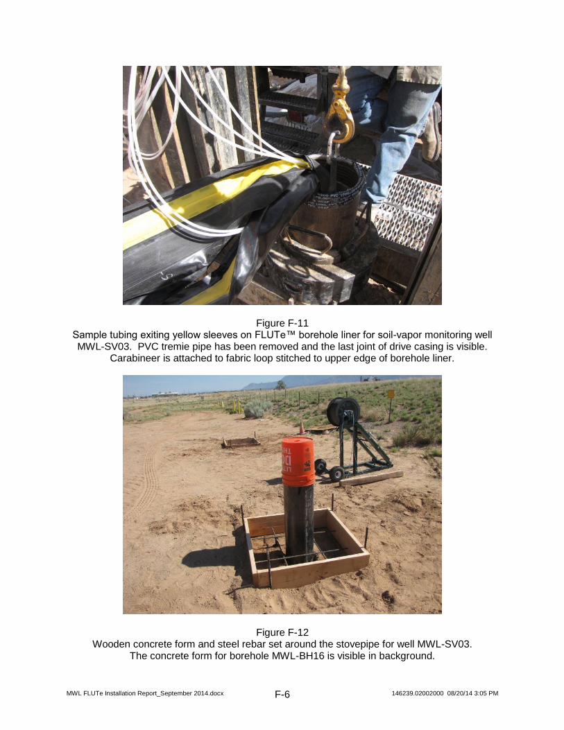
Figure F-11 Sample tubing exiting yellow sleeves on FLUTe™ borehole liner for soil-vapor monitoring well MWL-SV03. PVC tremie pipe has been removed and the last joint of drive casing is visible.
Carabineer is attached to fabric loop stitched to upper edge of borehole liner.
Figure F-12 Wooden concrete form and steel rebar set around the stovepipe for well MWL-SV03.
The concrete form for borehole MWL-BH16 is visible in background.

MWL FLUTe Installation Report_September 2014.docx 146239.02002000 08/20/14 3:05 PM F-7
Figure F-13 Flow testing with a vacuum pump of the sample ports at soil-vapor monitoring well MWL-SV03.
Figure F-14 Competed installation for soil-vapor monitoring well MWL-SV03.

MWL FLUTe Installation Report_September 2014.docx 146239.02002000 08/20/14 3:05 PM F-8
Figure F-15 Competed installation for soil-vapor monitoring well MWL-SV04.
Figure F-16 Competed installation for soil-vapor monitoring well MWL-SV05.