enterprise architecture analysis
TRANSCRIPT

Enterprise Modelling and Information Systems ArchitecturesVol. 3, No. 2, December 2008Enterprise Architecture Analysis 31
André Vasconcelos, Pedro Sousa, José Tribolet
Enterprise Architecture Analysis
An Information System Evaluation Approach
The definition of an Enterprise Architecture (EA) has a central role in implementing Information Systems (ISs)that proactively contribute to business and Information Technology (IT) alignment. In this paper, using a set of keyconcepts for the Information System Architecture (ISA) specification (formalized in a UML profile), 16 metrics areproposed for ISA suitability assessment considering a set of required quality characteristics. This paper also proposesan exploratory approach for the ISA definition process. This approach combines EA primitives and metrics in orderto support multi-criteria ISA selection. The proposals presented in this research are applied in the definition, evalu-ation and comparing of different architectural options for the new Portuguese National identification documentproject (the Citizen Card project).
1 Introduction
The Information System Architecture (ISA) definitionhas a key role in the implementation of InformationSystems (ISs) that actively contribute to business andInformation Technology (IT) alignment – ensuringthat the ISs are robust, IT independent, flexible andadaptable to business needs.
The research described in this paper, supported on aset of information system founding concepts (or ar-chitectural primitives), contributes on the estimationof the ISA suitability for a set of quality characteris-tics.
Using a UML profile for ISA modelling, we will presenta set of metrics for assessing the ISA qualities; thesemetrics are formalized using OCL and are integratedin an approach for constructing an ISA, with specificarchitecture evaluation tasks.
In the next section an ISA modelling framework, thatconsiders the enterprise, business, organizational, in-formation system, information, application and tech-nology concepts, is introduced. In the third section weformalize a coherent set of ISA evaluation metrics,supported in the framework introduced in the previ-ous section. Next section describes the metrics appli-cation to the Portuguese Citizen Card Project. Finallywe draw the major conclusions of this research andpropose future exploration paths.
2 ISA Modelling
Nowadays the ISA is considered a critical success fac-tor for the implementation of the organizational busi-ness strategy. According to [Zach97], ISA is “thedetermining factor, the factor that separates the win-ners from the losers, the successful and the failures,the acquiring from the acquired, the survivors fromthe others”. In spite of the potential advantages ofdefining an ISA - namely better alignment betweenbusiness and IT, interface and integration cost reduc-tions, coherent data sharing and cheaper IT mainte-nance - there is currently no standard organizationalpraxis to define it. Moreover, the tools for represent-ing an ISA, at informational, application and techno-logical levels, and its dependences with businesslevel, in a standard, normalized and simple way arenot available off-the-shelf for Enterprise Architects[Zach99], [Boar99].
Organizational Engineering Center (CEO), consideringother authors’ research ([ErPe00], [MCL+99],[OMG06a]), in [VCN+01], proposed a framework forenterprise modelling (CEOF 2001). The CEOF 2001provided a restricted set of business objects, definedin a UML profile [OMG06a], used for Enterprise mod-elling. CEOF 2001 has been extended for better sup-porting ISA modelling, at informational, applicationand technological levels, as well as its relationshipswith the business model.

Enterprise Modelling and Information Systems ArchitecturesVol. 3, No. 2, December 2008
André Vasconcelos, Pedro Sousa, José Tribolet32
Figure 1 introduces the core concepts proposed in theCEOF (simplified) metamodel for ISA modelling – in-tegrated in an Enterprise Architecture (EA) modellingframework. The three major architecture levels thatdefine the EA are: the Business, Organizational andInformation Systems Architectures. At ISA level theconcepts of information entity («Information Entity»),application block («IS Block»), technology block («ITBlock») and business service («Business Service»)are the root primitives for expressing the InformationArchitecture, the Application Architecture, the Tech-nology Architecture and the relations between the ISAand the business, respectively. Thus, CEOF proposesto describe the ISA from its information, applicationand technology components. Furthermore, the rela-tion between the ISA and the business model is ac-complished using services that directly supportbusiness process needs (even between the ISA prim-itives the service concept is also used to express thedependencies and relations).
For further detail on the CEO framework architecturalprimitive (including its UML profile, attributes, OCL re-strictions, associations, shapes, and presentation op-tions) see [Vasc06], [STV+06], [VaST03] and[VCN+01].
3 ISA Evaluation
Though Information System Architecture (ISA) is cur-rently recognized as an essential step in the processof building Enterprise Information Systems (EIS)aligned with business needs, there are not tools that
support the Information System (IS) architect in ac-cessing (during “design time”) the impact of his or herdecisions on the global ISA. Moreover, other ISAstakeholders that might have limited knowledge onISA matters (as business people, software engineers,infrastructure experts) do not have simple methods ortools to quickly and automatically evaluate an ISAconsidering a set of desired IS qualities driven fromthe business context.
Using the CEO UML profile for ISA (described in theprevious section), we defined a set of metrics, speci-fied in OCL [OMG06b] and supported on the architec-tural primitives and attributes of CEOF. The metricsare defined considering a set of ISA qualities and prin-ciples next introduced.
3.1 Information System Qualities
In the software engineering domain there is someconsensus on the set of quality characteristics desiredin a software program; these characteristics are spec-ified in the international standard ISO 9126 [ISO01].
In the Information System domain this consensus andnormalization do not exist; although related research,mostly, at technological level of the ISA, proposessome IS qualities – for example [KhHo04] presents aset of quality attributes for large scale software sys-tems (as performance, scalability, portability, robust-ness, accuracy and reliability), the Open Group (usingTOGAF Framework) also describes a set of qualitiesthat the IS should present [OpGr03]. Though thetechnology architecture might be analyzed consider-ing most of the ISO 9126 qualities, the applicationand information architectures qualities and the align-ment between the enterprise architectures are not ex-pressed in ISO 9126 qualities. Thus, in this paper, weextend the ISO 9126 for ISA evaluation. Besideschanging the scope of each quality characteristic forthe IS domain – namely, changing the words “prod-uct” or “software product”, in each ISO 9126 quality,to “Information Systems” – we propose the followingchanges to the ISO 9126 qualities1:
• Functionality – Information Systems abilityto provide services that fulfil strategies andbusiness goals;
• Interoperability – Information Systems abil-ity to interact at technical and semantic level[IDAB03].
• Usability – since this characteristic is notmeasurable in an ISA, it won’t be consideredwhen analyzing an ISA (as its sub character-istics).
1. Only the changes to ISO9126 qualities and new qualities are described.
Figure 1: Simplified metamodel of CEO Framework
E n te rp r is e A rc h ite c tu re
In fo rm a tio n S y s te m A rc h ite c tu re
G o a l
P ro c e s s R e s o u rc e
IS B lo c kB u s in e s s S e rv ic e
In fo rm a tio nE n tity
B u s in e s s A rc h ite c tu re
O rg a n iza tio n a l A rc h ite c tu re
IT B lo c k
**
**
**
**
*
*
**
*
*
Enterprise Modelling and Information Systems ArchitecturesVol. 3, No. 2, December 2008Enterprise Architecture Analysis 33
In order to consider the alignment in an ISA a newquality characteristic is introduced: Alignment – abil-ity of the ISA components to operate according to therequirements/resources requested/provided in someother architectural level with the goal to improve or-ganizational performance over time (the alignment isconsider between business, application, informationand technology architectures).
3.2 Metrics for ISA Evaluation
According to Tom DeMarco “You cannot control whatyou cannot measure” [DeMa82]; the metrics aim is toprovide information to support quantitative decision-making during the system lifecycle, in order to “meas-ure” the architecture (and control it!).
In this paper, the authors enforce the metrics coher-ence and correctness using the rules and principlesproposed in [AbCa94] and [Hend96].
The metrics next described were developed iterative-ly, using, as starting point, the research from special-ists in specific domains and the adaptation andextension of several software engineering metrics tothe ISA domain (providing the chance of reusing theconsolidate knowledge from a related research area -software engineering).
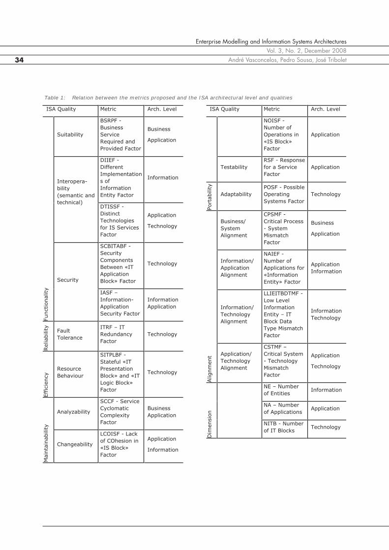
This paper proposes 16 metrics for ISA evaluationthat pretend to quantify the set of quality character-istics for ISs (based on ISO 9126) and on the archi-tectural primitives specified in the CEOF UML profile.Each of the metrics proposed is focused on the evalu-ation of an ISA quality at a defined architectural level(information, application or technology architec-tures). Table 1 presents an integrated overview onthe metrics proposed and the qualities addressed.
In order to ensure the metrics correctness and mini-mize misinterpretations, all the metrics are specifiedusing OCL (for space limitations the OCL code is notpresented in the article) and supported on the CEOFUML primitives (previously described).
The metrics are next described, according to the ISAquality assessed.
3.2.1 Functionality Metrics
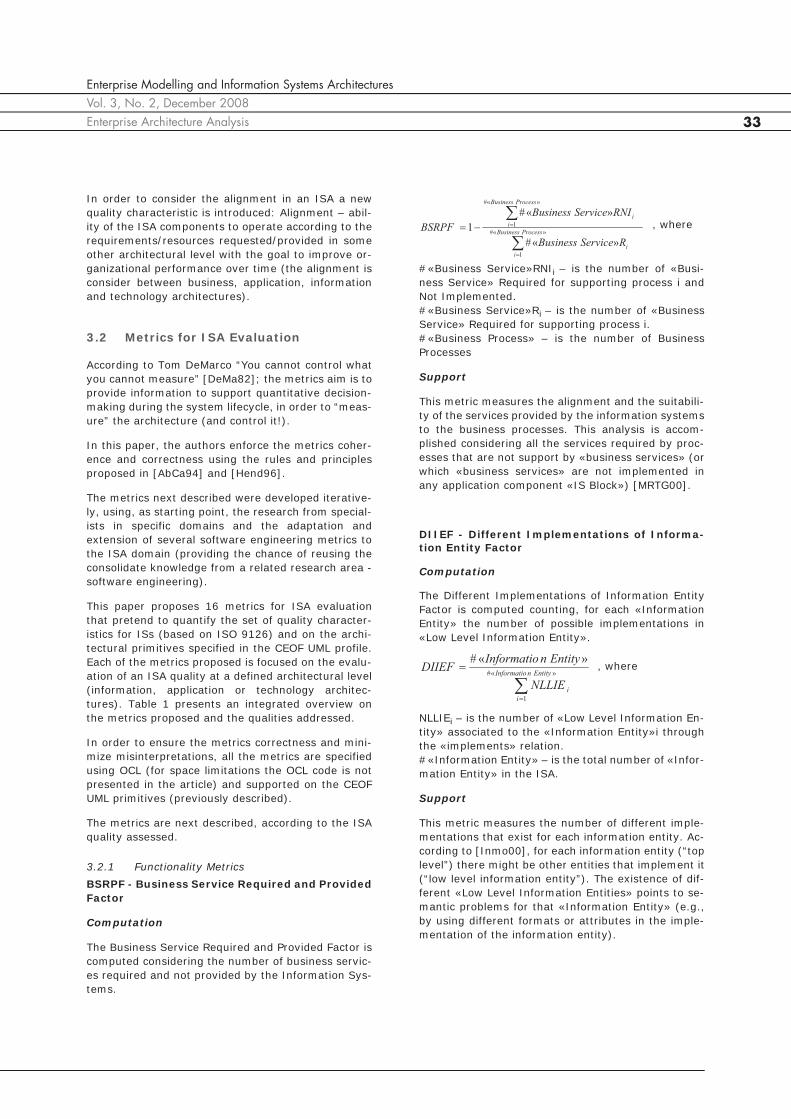
BSRPF - Business Service Required and ProvidedFactor
Computation
The Business Service Required and Provided Factor iscomputed considering the number of business servic-es required and not provided by the Information Sys-tems.
#«Business Service»RNIi – is the number of «Busi-ness Service» Required for supporting process i andNot Implemented.#«Business Service»Ri – is the number of «BusinessService» Required for supporting process i.#«Business Process» – is the number of BusinessProcesses
Support
This metric measures the alignment and the suitabili-ty of the services provided by the information systemsto the business processes. This analysis is accom-plished considering all the services required by proc-esses that are not support by «business services» (orwhich «business services» are not implemented inany application component «IS Block») [MRTG00].
DIIEF - Different Implementations of Informa-tion Entity Factor
Computation
The Different Implementations of Information EntityFactor is computed counting, for each «InformationEntity» the number of possible implementations in«Low Level Information Entity».
NLLIEi – is the number of «Low Level Information En-tity» associated to the «Information Entity»i throughthe «implements» relation.#«Information Entity» – is the total number of «Infor-mation Entity» in the ISA.
Support
This metric measures the number of different imple-mentations that exist for each information entity. Ac-cording to [Inmo00], for each information entity (“toplevel”) there might be other entities that implement it(“low level information entity”). The existence of dif-ferent «Low Level Information Entities» points to se-mantic problems for that «Information Entity» (e.g.,by using different formats or attributes in the imple-mentation of the information entity).
, where»«#
1
»«#
1
»«#
»«#
1ProcessBusiness
i
i
ProcessBusiness
i
i
RServiceBusiness
RNIServiceBusiness
BSRPF
»«#
1
»«#EntitynInformatio
i
iNLLIE
EntitynInformatioDIIEF , where
Enterprise Modelling and Information Systems ArchitecturesVol. 3, No. 2, December 2008
André Vasconcelos, Pedro Sousa, José Tribolet34
ISA Quality Metric Arch. Level
Functionality
Suitability
BSRPF -
Business
Service
Required and
Provided Factor
Business
Application
Interopera-
bility
(semantic and
technical)
DIIEF -
Different
Implementation
s of
Information
Entity Factor
Information
DTISSF -
Distinct
Technologies
for IS Services
Factor
Application
Technology
Security
SCBITABF -
Security
Components
Between «IT
Application
Block» Factor
Technology
IASF –
Information-
Application
Security Factor
Information
Application
Reliability
Fault
Tolerance
ITRF – IT
Redundancy
Factor
Technology
Eff
icie
ncy Resource
Behaviour
SITPLBF -
Stateful «IT
Presentation
Block» and «IT
Logic Block»
Factor
Technology
Main
tain
ability
Analyzability
SCCF - Service
Cyclomatic
Complexity
Factor
Business
Application
Changeability
LCOISF - Lack
of COhesion in
«IS Block»
Factor
Application
Information
ISA Quality Metric Arch. Level
NOISF -
Number of
Operations in
«IS Block»
Factor
Application
Testability
RSF - Response
for a Service
Factor
Application
Port
ability
Adaptability
POSF - Possible
Operating
Systems Factor
Technology
Alignm
ent
Business/
System
Alignment
CPSMF -
Critical Process
- System
Mismatch
Factor
Business
Application
Information/
Application
Alignment
NAIEF -
Number of
Applications for
«Information
Entity» Factor
Application
Information
Information/
Technology
Alignment
LLIEITBDTMF -
Low Level
Information
Entity – IT
Block Data
Type Mismatch
Factor
Information
Technology
Application/
Technology
Alignment
CSTMF –
Critical System
- Technology
Mismatch
Factor
Application
Technology
Dim
ensio
n
NE – Number
of Entities Information
NA – Number
of Applications Application
NITB - Number
of IT Blocks Technology
Table 1: Relation between the metrics proposed and the ISA architectural level and qualities

Enterprise Modelling and Information Systems ArchitecturesVol. 3, No. 2, December 2008Enterprise Architecture Analysis 35
DTISSF - Distinct Technologies for IS ServicesFactor
Computation
The Distinct Technologies for IS Services Factor iscomputed counting for each «IS Service» the numberof «IT Service» of type “Integration Service”.
#«IT Service» Integration i – is the number of «ITService», which attribute serviceType is equal to “In-tegration Service” that implements the «ISService» i.#«IS Service» – is the number of «IS Service» in theISA.
Support
The technical interoperability of a software architec-ture increases by providing the same interface in dif-ferent technologies [SaSu03]. In the same way, withthis metric the technical interoperability and portabil-ity of an EIS is analyzed as the average of the Tech-nologies that each application interface provides.
SCBITABF - Security Components Between «ITApplication Block» Factor
Computation
The Security Components Between «IT ApplicationBlock» Factor is computed counting, for each «IT Ap-plication Block» the minimal number of «IT Block»,which attribute “securityElement” is true, that is be-tween the path of that block and each of the remain-ing «IT Application Block».
Min{#SITBij} – is the minimal number of instances of«IT Block», which attribute “securityElement” has thevalue “true”, and is in the path between «IT Applica-tion Block»i and «IT Application Block»j.#«IT Application Block» – is the number of instancesof «IT Application Block».#«IT Block» – is the number of instances of «ITBlock».
Support
The ISA security is increased by putting security ele-ments on it, as IDS, firewalls, etc. Thus, this metric,is not limited to counting the number of security com-ponents but it also considers, for each application
component, the number of security components thatisolate it from other components.
IASF – Information-Application Security Factor
Computation
The Information-Application Security Factor is com-puted considering the number of information entitieswith high level security requirements supported in «ISBlocks» that also support information entities withouthigh security requirements and vice versa.
– is the number of «InformationEntities» that its Security attribute value is {Yes}supported in «IS Blocks» that support other «Infor-mation Entities» which Security attribute value is{No}; where an «Information Entity» is “supported”by an «IS Block» if and only if exists at least one «op-eration» provided by the «IS Block» that CUD the «In-formation Entity».
– is the number of «Informa-tion Entities» that its Security attribute value is {No}supported in «IS Blocks» that support other «Infor-mation Entities» which Security attribute value is{Yes}; where an «Information Entity» is “supported”by an «IS Block» if and only if exists at least one «op-eration» provided by the «IS Block» that CUD the «In-formation Entity».#«Information Entity» – is the number of informationentities
Support
According to [SoPM04] applications should manage informa-tion entities of the same security level.
3.2.2 Reliability Metrics
ITRF – IT Redundancy Factor
Computation
The IT Redundancy Factor is computed counting the«IT Block» which attribute “redundantElement” istrue.
#RITB – is the number of «IT Block» which attribute“redundantElement” has the value true.#«IT Block» – is the number of «IT Block».
»«#
1
»«#
»«#1
ServiceIS
i
inIntegratioServiceIT
ServiceISDTISSF , where
»«#»«#
}{##
1
»«#
1
ITBlockBlocknApplicatioIT
SITBMin
SCBITABF
BlocknApplicatioIT
i
BlocknApplicatioIT
j
ij
, where
»«#
}{#}{#1
nEntityInformatio
ISBlocknEntityInformatioISBlocknEntityInformatioIASF SNSNSs
, where
»«#
#
BlockIT
RITBITRF , where
}{# SNS ISBlocknEntityInformatio
}{# NSS ISBlocknEntityInformatio

Enterprise Modelling and Information Systems ArchitecturesVol. 3, No. 2, December 2008
André Vasconcelos, Pedro Sousa, José Tribolet36
Support
The Fault tolerance of an ISA tends to increase by us-ing redundant elements [Varg00]. This metrics con-siders this fact.
3.2.3 Efficiency MetricsSITPLBF - Stateful «IT Presentation Block» and«IT Logic Block» Factor
Computation
The Stateful «IT Presentation Block» and «IT LogicBlock» Factor is computed counting the number of «ITPresentation Block» and «IT Logic Block» that its at-tribute “state” value is “stateful”
#SITPLB – is the number of «IT Presentation Block»and «IT Logic Block» that its attribute “state” value is“stateful”.#«IT Presentation Block» – is the number of «IT Pres-entation Block».#«IT Logic Block» – is the number of «IT LogicBlock».
Support
The Scalability of an EIS is increased if business andpresentation components do not keep the state (sinceit will be easier for implementing new parallel instanc-es of these ISA components) [BEA06].The Scalability of an ISA tends to grow if the «IT Pres-entation Blocks» and the «IT Logic Blocks» do notpreserve the application state (stateless) – the «ITData Blocks» should be the ones to keep applicationstate.
3.2.4 Maintainability Metrics
SCCF - Service Cyclomatic Complexity Factor
Computation
The Service Cyclomatic Complexity Factor is comput-ed considering the number of dependencies between«IS Blocks» subtracted by the number of «IS Blocks»that support the service, for each service.
ei – is the number of dependencies between «ISBlock» for the service i.ni – is the number of «IS Blocks» that support theservice i.#«Business Service» – is the number of «BusinessServices».#«IS Service» – is the number of «IS Services»
Support
Like [McCa76], for the software engineering area,considering that the higher the number of paths in aprogram, the higher its control flow complexity prob-ably will be, in [VaST05] is proposed a similar metricfor evaluate the complexity of an ISA in the supportof the business services – considering that the com-plexity, for each service, is measure by the differencebetween the number of dependencies and applica-tions involved.
LCOISF - Lack of COhesion in «IS Block» Factor
Computation
The Lack of COhesion in «IS Block» Factor is comput-ed counting the number of sets of information entitiesthat are used by distinct functionalities of the sameapplication (provided by operations in «IS Blocks»)
#LCOISi – is the number of sets of «Information Enti-ties» that are used by «operations» distinct of the «ISBlock» i;.#«IS Block» – is the number of «IS Blocks».#«IS Operation» – is the number of «IS Operation».#«Information Entity» – is the number of « Informa-tion Entity».
Support
This metric measure the correlation between applica-tion blocks and the information entities used in thatapplication block.It is quantified by the average of the number of setsof information entities that are used by distinct oper-ations of the same application [VaST05].
NOISF - Number of Operations in «IS Block»Factor
Computation
The Number of Operations in «IS Block» Factor iscomputed dividing the number of «IS Blocks» by thenumber of operations on each «IS Block».
#«operation»«IS Block»i – is the number of operationson «IS Block» i.#«IS Block» – is the number of «IS Block»
»«#»Pr«#
#1SITPLBF
LogicBlockITBlockesentationIT
SITPLB , where
, where»«#»«#
1
2
»«#»«#ServiceISServiceBusiness
i
ii ne
ServiceISServiceBusinessSCCF
»«#»«#»«#
#
1
#
1
EntitynInformatioOperationISBlockIS
LCOIS
LCOISF
BlockIS
i
i
, where
BlockIS
i
iISBlockoperationIS
BlockISNOISF
#
1
»«»«#
»«# , where

Enterprise Modelling and Information Systems ArchitecturesVol. 3, No. 2, December 2008Enterprise Architecture Analysis 37
Support
The simplicity to adapt/improve operations in an ISAto new business demands is maximized when the im-pact of changing each operation is reduced to a singleapplication block («IS Block»). This metric measuresthis fact.This metric was defined considering the similar soft-ware engineering metric “Average number of meth-ods per class”, that considers the existing methods ineach class [AbCa94].
RSF - Response for a Service Factor
Computation
The Response for a Service Factor is computed byconsidering the average of the number of «IS Blocks»that might be used to support each «Service».
#«IS Block»i – is the number of «IS Blocks» involvedin supporting service i.#«Business Service» – is the number of «BusinessServices».#«IS Service» – is the number of «IS Services».
Support
This metric is similar to the software metric “Re-sponse For a Class” – see [ChKe94] and [BaBM96] forfurther details – that computes the number of meth-ods that can potentially be executed in response to amessage received. In [VaST05] this metric is pro-posed (Average Response for a Service) and it com-putes the number of «IS Blocks» that might be usedto support a service. Recent research [SoPM04] suggests that each busi-ness process should be supported by the less numberof applications as possible – which is measured by thismetric.
3.2.5 Portability MetricsPOSF - Possible Operating Systems Factor
Computation
The Possible Operating Systems Factor is computedby counting, on each application («IT ApplicationBlock»), the number of possible operating systems(families).
NPOSi – is the number of possible operating systemsfamilies that the «IT Application Block»i supports.#«IT Application Block» – is the number of «IT Appli-cation Block» in the ISA.
Support
The portability and Technical Interoperability in anISA increase with the number of possible platformswhere ISA components are able to operate [SaSu03].
3.2.6 Alignment Metrics
CPSMF - Critical Process - System Mismatch Fac-tor
Computation
The Critical Process - System Mismatch is computedby counting the number of critical business processessupported by «IS Blocks» that also support non-criti-cal business processes and the number of non-criticalbusiness processes supported by «IS Blocks» thatalso support critical business processes.
– is the number of critical process-es supported by «IS Blocks» that support other non-critical processes.
– is the number of non-critical proc-esses supported by «IS Blocks» that support othercritical processes.#«Process» – is the number of processes.
Support
As described in [SoPM04] the critical business proc-esses should be supported by different applicationsthan non-critical business processes.
NAIEF - Number of Applications for «Informa-tion Entity» Factor
Computation
The Number of Applications for «Information Entity»Factor is computed counting the average number ofapplications («IS Blocks») that through its «opera-tions» support each «information entity».
– is the number of«IS Blocks» in which exists an «operation» that CUD(Creates, Updates or Deletes) the «information enti-ty» i.
}{Pr# CNCISBlockocess }{Pr# CNC ISBlockocess
inEntityInformatioCUDoperationISBlocks »«»«#
»«#»«#
1
»«#
»«#»«#ServiceISServiceBusiness
i
i
ISA
BlockIS
ServiceISServiceBusinessRSF , where
, where»«#
1
»«#1
BlocknApplicatioIT
i
iNPOS
BlocknApplicatioITPOSF
»«#
}{#}{#1
Process
ISBlockProcessISBlockProcessCPSMF CNCNCC
, where
}{Pr# NCC ISBlockocess
EntitynInformatio
i
inEntityInformatioCUDnISOperatioISBlocks
EntitynInformatioNAIEF
#
1
»«»«#
»«#
, where

Enterprise Modelling and Information Systems ArchitecturesVol. 3, No. 2, December 2008
André Vasconcelos, Pedro Sousa, José Tribolet38
#«Information Entity» – is the number of «Informa-tion Entities».
Support
According to [SoPM04] each information entity shouldbe managed by a single application.
LLIEITBDTMF - Low Level Information Entity –IT Block Data Type Mismatch Factor
Computation
The Low Level Information Entity – IT Block Data TypeMismatch Factor is computed counting the number of«Low Level Information Entity» that are “primitive”that (according to the attribute “informationEntityDa-ta”) supported in «IT Block» that also support «LowLevel Information Entity» that are “derived” and viceversa.
– is the number of«Low Level Information Entity» which informationEn-tityData attribute is {Primitive} supported in «ITBlock» that support other «Low Level Information En-tity» which attribute informationEntityData is differ-ent from {Primitive}.
– is the number of«Low Level Information Entity» which informationEn-tityData attribute is {Derived} supported in «ITBlock» that support other «Low Level Information En-tity» which attribute informationEntityData is differ-ent from {Derived}.#«Low Level Information Entity» – number of low lev-el information entities.
Support
According to Inmon the primitive and derived datapresent important differences on performance, ac-cessing patterns, availability, among others issues[Inmo92]. Thus, is considered a “good architectural practice” touse different technology components to support prim-itive and derived data – using this metric it is possibleto measure the alignment between the technologyand the information architectures.
CSTMF – Critical System - Technology MismatchFactor
Computation
The Critical System - Technology Mismatch Factor iscomputed counting the number of «IS Block» consid-ered critical (for supporting exclusively critical proc-esses) supported in «IT Block» that support «ISBlock» not critical and vice versa.
– is the number of «ISBlock» consid-ered critical supported in «IT Block» that support oth-er «ISBlock» besides the critical ones (where an «ISBlock» is considered critical if it supports exclusivelycritical «process»).
– is the number of «ISBlock» con-sidered not critical supported in «IT Block» that sup-port other «ISBlock» besides the non-critical ones(where an «IS Block» is considered not critical if itsupports exclusively not critical «process»).#«IS Block» – is the number of «IS Block».
Support
As critical business processes should be supported bydifferent applications than non-critical business proc-esses [SoPM04], these applications should be imple-mented in technology components different than theones that implement applications that support non-critical business processes.
3.3 An Exploratory Approach for Building an ISA
Considering the evaluation metrics previously intro-duced the authors propose an exploratory approachfor defining and selecting an ISA according to a set ofquality characteristics.
The “traditional” process for building an ISA is de-scribed in Figure 2 (a); in the “traditional” approachthe ISA is defined and implemented without consider-ing the qualities it should provide. In Figure 2 (b) anew approach is proposed that – besides modellingthe ISA using a set of formalized UML primitives – hasexplicit control and evaluation tasks on the architec-ture quality (providing feedback to the ISA definitionprocess).
This (exploratory) approach provides a set of concep-tual tools for the “IS architects” use the primitives andmetrics developed in our research. The approach isbased on the major steps and tasks of Spewak Enter-prise Architecture Planning (EAP) methodology[SpHi92] (however it could be applied to other archi-
»«#
}{#
»«#
}{#1FLLIEITBDTM
ntityformationELowLevelIn
ITBlockntityformationELowLevelIn
ntityformationELowLevelIn
ITBlockntityformationELowLevelIn
NDD
NPP
, where
}{# NPP ITBlockntityformationELowLevelIn
}{# NDD ITBlockntityformationELowLevelIn
»«#
}{#}{#1
ISBlock
ITBlockISBlockITBlockISBlockCSTMF CNCNCC
, where
}{# NCC ITBlockISBlock
}{# CNC ITBlockISBlock

Enterprise Modelling and Information Systems ArchitecturesVol. 3, No. 2, December 2008Enterprise Architecture Analysis 39
tecture building approaches). Next we will just identi-fy the changes proposed to the EAP approach.
Thus, for modelling the current ISA and businessprocesses the task suggested by [SpHi92] should beaccomplished, but using the CEOF modelling primi-tives to represent the current situation.
In the definition of the ISA, a new step should be add-ed: the identification of the qualities that the ISAshould fulfil. The architecture team should weighteach quality (according to its importance), consider-ing the qualities and ISA levels identified in Table 1.
After this step, the definition of the ISA should be de-veloped according to EAP methodology, by modellingthe information, application and technology architec-tures (always using CEOF UML primitives); each ar-chitecture (at information, application and technologylevels) should be evaluated (using the metrics de-scribed in the previous section) and compared to thecurrent (“AS-IS”) architecture or against other possi-ble design options presented by the project team (seeFigure 3 (a)).
Finally, the project team should apply all the metricsintroduced in the previous section (including the di-mension metrics), at each (possible) architecture.
After the relative weight of each quality characteristicis combined with each metric, a final value is ob-tained. In order to select the “best” architecture it isrecommended that the project team develop a cost-benefit analysis (obtaining the cost of each architec-ture using the dimension metrics) and perform a sen-sibility analysis (in order to better understand theimpact of the architecture’s design choices on the al-ternative ISA) - see Figure 3 (b).
This approach is used in the Portuguese Citizen CardArchitecture described next.
4 The Portuguese Citizen Card Project
This section presents the result of using the primi-tives, metrics and approach, previously described, fordefining the ISA of a Portuguese Government project.
4.1 The Project Context
The Portuguese Government decided to implement anew mandatory national identification card that com-bines and replaces five identification cards (that cur-rent the citizens need for interact with the publicadministration). This card is a physical high securedocument (that allows the visual identification of a cit-izen) and it is also a digital document (that allows thecitizen to identify himself/herself and to electronicallysign documents) – see Figure 4.
Considering the technological, architectural, legal,and political challenges of the project and the shorttime available for its implementation (the project def-inition started in June 2005 and the system should beissuing real cards by the end of 2006) the projectteam decided to develop a Proof of Concept (PoC),based on the know-how of different companies andpublic agencies and on the best practices of othersimilar projects. The ISA defined for the PoC was fo-cussed on “demonstrating the concepts” of electronicidentity and interoperability, and was not much
Model Current ISA
«Process» «Resource»
ISA (AS-IS) Define ISA
«Process» «Resource»
ISA (TO-BE) Implement ISA
«Process» «Resource»
Information System
Model Current ISA
«Process» «Resource»
ISA (AS-IS) Define ISA
«Process»
Implement ISA
«Process» «Resource»
Information System
Define desired ISA qualities
«Process» «Resource»
ISA Qualities
«Resource»
ISA (TO-BE)
According to quality
characteris -tics
Y
Evaluate ISA
«Process»
«Resource»
ISA (TO-BE)
N
(a)
(b)
Figure 2: Traditional (a) and proposed (b) approach for building an ISA

Enterprise Modelling and Information Systems ArchitecturesVol. 3, No. 2, December 2008
André Vasconcelos, Pedro Sousa, José Tribolet40
«Resource»
ISA (TO-BE)
Apply the metrics
«Process»
«Resource»
ISA Qualities«Resource»
Possible Information
Architectures
«Resource»Possible
Application Architectures
«Resource»
Possible IT Architectures
Select the ISA
«Process»
«Resource»
Architectures scores
Perform cost-benefit analysis
«Process»
Perform sensibility analysis
«Process»
«Resource»
Cost-benefit analysis
«Resource»
Sensibility analysis
Information Architecture
Definition
«Process»
Application Architecture
Definition
«Process»
IT Architecture Definition
«Process»
«Resource»Possible
Information Architectures
«Resource»Possible
Application Architectures
«Resource»
Possible IT Architectures
«Resource»
ISA (TO-BE)Evaluate ISA
«Process»
«Resource»
ISA QualitiesDefine desired ISA qualities
«Process»
(a)
(b)
Figure 3: Detailing sub-processes of the “Define ISA” (a) and “Evaluate ISA” (b) processes (part of the building ISA approach proposed)
concerned on the reliability, security, portability or ef-ficiency of the resulting information systems.
Simultaneously with the PoC ISA implementation (fordemonstration purposes) the project team modelledthe business processes and specified an ISA (thatconsidered the PoC architecture with some changes)– we will label this the “final ISA”. The final ISA wasdefined considering the impact of other architecturaloptions on the PoC architecture – according to the
metrics, notation and approach described in the pre-vious sections.
We describe this approach and the architectural re-sults accomplished2.
4.2 The Business Architecture
Figure 5 presents the top level business process of thecitizen card request and use. The project team de-tailed this (and other) process – however consideringthe focus of this paper we will not present further de-tails on the business architecture (but on the ISA).
2. Considering the size and complexity of this project, only part of the metrics applied are presented in this paper.Figure 4: Portuguese Citizen Card (CC)

Enterprise Modelling and Information Systems ArchitecturesVol. 3, No. 2, December 2008Enterprise Architecture Analysis 41
4.3 Selecting the “right” ISA
4.3.1 ISA Qualities IdentificationAccording to the approach previous described, theproject team defined weights for each quality charac-teristic (according to the project priorities and goals)– Table 2 presents the result. This table will supportthe selection of the ISA to implement.
4.3.2 Information Architecture
The information architecture defined for the PoC ismodelled in Figure 6 (a). For the final ISA(Figure 6 (b)) the “Delivery Note” and “Receipt” wereadded to the architecture – that previously, for dem-onstration purposes, weren’t considered important.
The «Low Level Information Entities», derived fromeach «information entity» were next identified. ThePoC and the final information architectures presentsome differences at this level; for example, the for-mat of the “Address” information entity, in the PoCwas considered similar for all the IS (Figure 7 (a));however, in the final ISA, most of the existing IS al-ready had distinct attributes for the address (besidesthe need for keeping the successive citizen addressesduring his/her life) – Figure 7 (b).
Figure 5: Citizen Card high level business process
Import
.
(0-1
0)
Sub-Quality
Import
.
(0-1
0)
Architectural Level
Import
.
(0-1
0)
Functionality
9
Suitability 9Business Application --
Semantic Interoperability 3 Information --
Technical
Interoperability 3Application Technology --
Security 10
Technology 8
Information Application 5
Reliability
5 Fault Tolerance -- Technology --
Effic
iency
4Resource Behaviour -- Technology --
Main
tain
ability
6
Analyzability 3Business Application --
Changeability 7
Application Information 5
Application 5
Testability 8 Application --
Port
ability
3 Adaptability -- Technology --
Alignm
ent
7
Business/ SystemAlignment
8Application Information --
Information/ Application Alignment
8Information Technology --
Information/ Technology Alignment
8Application Technology --
Application/ Technology Alignment
8Application Information --
Table 2: Qualities weights defined for the CC ISA
«Information Entity»
Citizen
«Information Entity»
Card
«Information Entity»
CC Process
«Information Entity»
Personalization Data
«Information Entity»
BiometricData
«Information Entity»
Certificate
«Information Entity»
Address
«Information Entity»
PIN Letter
<owns
has1 1
1
*2
*
1
*
*
11
1 *
1 *
1
*
«Information Entity»
Delivery Note
«Information Entity»
Receipt
1
*
1 *
*
«Information Entity»
Citizen
«Information Entity»
Card
«Information Entity»
CC Process
«Information Entity»
Personalization Data
«Information Entity»
BiometricData
«Information Entity»
Certificate
«Information Entity»
Address
«Information Entity»
PIN Letter
<owns
has1 1
1
*2
*
1
*
*
11
1 *
1 *
1
*
Figure 6: Citizen Card PoC (a) and final (b) Infor-mation Architecture
(a)
(b)
Card Life Cycle Process
Citizen Perspective
No
«Process»«Process»
Apply for
Citizen Card
«Process»
Cancel Card
«Process»
Receive Card
«Process»
Apply for
Citizen Card
«Process»
Cancel Card
«Process»
Receive Card
«Resource»
: Citizen Card
«Process»
Use CardValid
Card?
Yes
«Resource»
: Citizen Card
«Process»
Use CardValid
Card?

Enterprise Modelling and Information Systems ArchitecturesVol. 3, No. 2, December 2008
André Vasconcelos, Pedro Sousa, José Tribolet42
67,03
2
11111115
8»«#)(
»«#
1
EntitynInformatio
i
iNLLIE
EntitynInformatioPoCDIIEF
42,012
5
1111152426
10»«#)(
»«#
1
EntitynInformatio
i
iNLLIE
EntitynInformatioFinalDIIEF
Considering all the information entities and low levelinformation entities, in order to quantify the semanticinteroperability of the PoC and the final architecture,the metric DIIEF (“Different Implementations of In-formation Entity Factor”) was computed.
For the PoC ISA:
And for the Final ISA:
Thus, the semantic interoperability of the PoC is high-er than the final ISA. However, the implementation ofthe PoC would imply changing the existing informa-tion systems (of the public agencies involved) – whichwas not considered in the project timeframe.
4.3.3 Application Architecture
The PoC and final application architectures are mod-elled in Figure 8 (a) and Figure 8 (b), respectively. AsFigure 8 (a) presents, some application componentswere not consider in the PoC architecture (since theywere not important to demonstrate the concepts) butrevealed to be important to support the Citizen Cardbusiness processes (like transportation or paymentactivities).
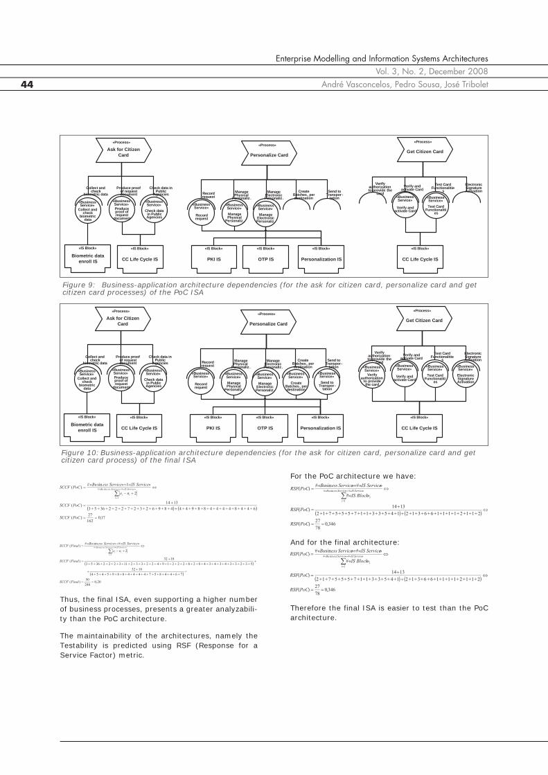
Figure 9 and Figure 10 describe the application archi-tecture support for the processes “Ask for CitizenCard”, “Personalize Card” and “Get Citizen Card”, inthe PoC and final architectures – once again, in thePoC some business process components are not sup-ported by the «IS Block».
Considering all the processes and their relations – be-sides the processes model in Figure 9 and Figure 10 –using the metric BSRPF (Business Service Required
and Provided Factor) we have for PoC and final archi-tectures:
This metric values point that the ISA implemented inthe PoC is less suitable to the business needs than thefinal ISA (that completely supports the business serv-ices required).
The dependencies between the information and appli-cation architectures are described in Figure 11. Theinformation-application architectures alignment is an-alyzed using the NAIEF (“Number of Applications for«Information Entity» Factor”) metric.
The NAIEF metric points out that the information-ap-plication alignment is higher in the final ISA.
The changeability, at information-application level,for both architectures is high, according to the LCOISF(Lack of COhesion in «IS Block» Factor) metric.
The high value of this metric, in both architectures, isa consequence of the high affinity of the operationsfor each «IS Block» - since, almost always, the oper-ations in each «IS Block» share information entities(between themselves).
The changeability at application level can be estimat-ed using the NOISF (Number of Operations in «ISBlock» Factor) metric.
56,016
9
32
181
»sin«#
»sin«#
1)(»Prsin«#
1
»Prsin«#
1
ocessessBu
i
i
ocessessBu
i
i
RServiceessBu
RNIServiceessBu
PoCBSRPF
132
01
»sin«#
»sin«#
1)(»Prsin«#
1
»Prsin«#
1
ocessessBu
i
i
ocessessBu
i
i
RServiceessBu
RNIServiceessBu
FinalBSRPF
57,014
8
1+1+1+1+1+1+2+6
8)(
»«»«#
»«#)(
#
1
PoCNAIEF
nEntityInformatioCUDnISOperatioISBlocks
EntitynInformatioPoCNAIEF
EntitynInformatio
i
i
63,016
10
1+1+1+1111+1+2+6
10)(
»«»«#
»«#)(
#
1
FinalNAIEF
nEntityInformatioCUDnISOperatioISBlocks
EntitynInformatioFinalNAIEF
EntitynInformatio
i
i
99,01840
111
82310
1+1+2+1+1+1+1+1+1+11)(
»«#»«#»«#
#
1)(
#
1
PoCLCOISF
EntitynInformatioOperationISBlockIS
LCOIS
PoCLCOISF
BlockIS
i
i
00,13720
141
103112
1+1+1+2+1+2+1+1+1+1+1+11)(
»«#»«#»«#
#
1)(
#
1
FinalLCOISF
EntitynInformatioOperationISBlockIS
LCOIS
FinalLCOISF
BlockIS
i
i
Figure 7: Address Low Level Information Entities for PoC (a) and final (b) ISA
«Information Entity»
Address
«Low Level Information Entity»
Address
InformationEntityData = {Primitive}
«Information Entity»
Address
«Low Level Information Entity»
Address History
«Low Level Information Entity»
Taxpayer Address
«Low Level Information Entity»
Health Address
«Low Level Information Entity»
Canonical Address
«Low Level Information Entity»
Social Security Address
InformationEntityData = {Primitive}
InformationEntityData = {Primitive}
InformationEntityData = {Primitive}
InformationEntityData = {Primitive}
InformationEntityData = {Derived}

Enterprise Modelling and Information Systems ArchitecturesVol. 3, No. 2, December 2008Enterprise Architecture Analysis 43
This metrics points out that the PoC ISA has a higherchangeability (at application level), considering thesmaller number of operations, per «IS Block».
The information-application security is high in bothISAs since all the information entities required to bemanaged in a high security environment. Thus themetric IASF (Information-Application Security Factor)presents a maximum value for both architectures:
Figure 12 and Figure 13 present two sequence dia-grams, for the PoC and the final architectures, whichdescribe the system interaction for supporting the“ask for citizen card” business process.
Considering all the business processes (of the CitizenCard project), and the resulting sequence diagramsthe project team estimated the following qualities forboth architectures:
The Analyzability quality is estimated using the SCCF(Service Cyclomatic Complexity Factor) metric.
43,023
10
»«#
»«#)(
#
1
»«
BlockIS
i
iISBlockoperationIS
BlockISPoCNOISF
39,031
12
»«#
»«#)(
#
1
»«
BlockIS
i
iISBlockoperationIS
BlockISfinalNOISF
18
001
»«#
}{#}{#1)(
nEntityInformatio
ISBlocknEntityInformatioISBlocknEntityInformatioPoCIASF SNSNSs
110
001
»«#
}{#}{#1)(
nEntityInformatio
ISBlocknEntityInformatioISBlocknEntityInformatioFinalIASF SNSNSs
(a)
(b)
Figure 8: Citizen Card Application Architecture: PoC (a) and final (b) architecture
«IS Block»
OTP IS
«IS Block»
CC Life Cycle IS
«IS Block»
Biometric data enroll IS
«IS Block»
Interoperability IS
«IS Block»
Personalization IS
«IS Block»
PKI IS
«IS Block»
Health IS
«IS Block»
Finance IS
«IS Block»
Social Security IS
«IS Block»
Voters IS
«IS Block»
Civil ID IS
«IS Service»
Recolhe Biometria
«IS Service»Check
FinanceData
«IS Service»Check health data
«IS Service»Check Social
Security Data
«IS Service»Check Voters Data
«IS Service»Check data
Public agencies
«IS Service»Check Civil ID
data
«IS Service»
Manage Certificates
«IS Service»Check One-
Time-Password
«IS Service»
PersonalizeCard
«IS Service»Identity
Federation
«IS Service»Personalize
Card
«IS Block»
CC Contact Center
«IS Service»Process Status
«IS Block»
OTP IS
«IS Block»
CC Life Cycle IS
«IS Block»
Biometric data enroll IS
«IS Block»
Interoperability IS (CSF)
«IS Block»
Personalization IS
«IS Block»
PKI IS
«IS Block»Storage and
Processing Finger Print IS
«IS Block»
Health IS
«IS Block»
Finance IS
«IS Block»
Social Security IS
«IS Block»
Voters IS
«IS Block»
Civil ID IS
«IS Block»
Transport IS
«IS Service»
Recolhe Biometria
«IS Service»Check
FinanceData
«IS Service»Check health data
«IS Service»Check Social
Security Data
«IS Service»Check Voters Data
«IS Service»Check data
Public agencies
«IS Service»Check Civil ID
data
«IS Service»
Manage Fingerprint
«IS Service»
Manage Certificates
«IS Service»Check One-
Time-Password
«IS Service»
PersonalizeCard
«IS Service»Get
Transport Status
«IS Service»Personalizati
on and Transport
status
«IS Service»Identity
Federation
«IS Service»Personalize
Card
«IS Service»
Cancel Card
«IS Block»
CC Contact Center
«IS Service»Process Status
«IS Service»
Cancel Card
Enterprise Modelling and Information Systems ArchitecturesVol. 3, No. 2, December 2008
André Vasconcelos, Pedro Sousa, José Tribolet44
Thus, the final ISA, even supporting a higher numberof business processes, presents a greater analyzabili-ty than the PoC architecture.
The maintainability of the architectures, namely theTestability is predicted using RSF (Response for aService Factor) metric.
For the PoC architecture we have:
And for the final architecture:
Therefore the final ISA is easier to test than the PoCarchitecture.
17,0162
27)(
6+4+4+8+4+4+4+4+8+8+9+4+44+8+9+6+2+3+2+7+2+2+2+36+5+3
1314)(
2
»«#»sin«#)(
»«#»sin«#
1
PoCSCCF
PoCSCCF
ne
ServiceISServiceessBuPoCSCCF
ServiceISServiceessBu
i
ii
20,0248
50)(
7+6+4+4+8+5+7+4+4+4+4+8+8+9+5+4+5+4
1832
5+3+2+3+3+4+3+4+3+4+8+2+8+2+2+2+1+9+4+2+2+3+3+2+11+3+2+2+2+36+5+3
1832)(
2
»«#»sin«#)(
»«#»sin«#
1
FinalSCCF
FinalSCCF
ne
ServiceISServiceessBuFinalSCCF
ServiceISServiceessBu
i
ii
346,078
27)(
2+1+1+2+1+1+1+1+6+6+3+1+21+4+5+3+3+1+1+7+5+5+5+7+1+2
1314)(
»«#
»«#»sin«#)(
»«#»sin«#
1
PoCRSF
PoCRSF
BlockIS
ServiceISServiceessBuPoCRSF
ServiceISServiceessBu
i
i
346,078
27)(
2+1+1+2+1+1+1+1+6+6+3+1+21+4+5+3+3+1+1+7+5+5+5+7+1+2
1314)(
»«#
»«#»sin«#)(
»«#»sin«#
1
PoCRSF
PoCRSF
BlockIS
ServiceISServiceessBuPoCRSF
ServiceISServiceessBu
i
i
Ask for Citizen Card
«Process»
Collect and check
biometric dataProduce proof
of request document
Check data in Public
Agencies
Personalize Card
«Process»
Record request
Manage Physical
Personaliz .
Manage Electronic Personaliz .
Create Batches, per destination
Send to Transpor -
tation
«IS Block»
CC Life Cycle IS
«IS Block»
Biometric data enroll IS
«Business Service»
Collect and check
biometric data
«Business Service»Produce proof of request
document
«Business Service»
Check data in Public Agencies
«Business Service»
Record request
«Business Service»Manage Physical
Personaliz .
«Business Service»Manage
Electronic Personaliz .
«IS Block»
Personalization IS
«IS Block»
OTP IS
«IS Block»
PKI IS
Get Citizen Card
«Process»
Verify authorization to provide the
card
Verify and activate Card
Test Card Functionalitie
s
Electronic Signature Activation
«Business Service»
Verify and activate Card
«Business Service»Test Card
Functionalities
«IS Block»
CC Life Cycle IS
Figure 9: Business-application architecture dependencies (for the ask for citizen card, personalize card and getcitizen card processes) of the PoC ISA
Figure 10:Business-application architecture dependencies (for the ask for citizen card, personalize card and getcitizen card process) of the final ISA
Ask for Citizen Card
«Process»
Collect and check
biometric dataProduce proof
of request document
Check data in Public
Agencies
Personalize Card
«Process»
Record request
Manage Physical
Personaliz .
Manage Electronic Personaliz .
Create Batches, per destination
Send to Transpor -
tation
«IS Block»
CC Life Cycle IS
«IS Block»
Biometric data enroll IS
«Business Service»
Collect and check
biometric data
«Business Service»Produce proof of request
document
«Business Service»
Check data in Public Agencies
«Business Service»
Record request
«Business Service»Manage Physical
Personaliz .
«Business Service»Manage
Electronic Personaliz .
«Business Service»
Create Batches, per destination
«Business Service»Send to
Transpor -tation
«IS Block»
Personalization IS
«IS Block»
OTP IS
«IS Block»
PKI IS
Get Citizen Card
«Process»
Verify authorization to provide the
card
Verify and activate Card
Test Card Functionalitie
s
Electronic Signature Activation
«Business Service»
Verify authorization
to providethe card
«Business Service»
Verify and activate Card
«Business Service»Test Card
Functionalities
«Business Service»Electronic Signature Activation
«IS Block»
CC Life Cycle IS

Enterprise Modelling and Information Systems ArchitecturesVol. 3, No. 2, December 2008Enterprise Architecture Analysis 45
Figure 11:PoC (a) and final (b) Information and Application Architectures
«IS Block»
Biometric data enroll IS
StartEnroll (...)CollectPicture(...)CollectFingerPrint(...)CollectSignature (...)
R
«Information Entity»
Citizen
security = true
«Information Entity»
Biometric Data
security = true
CRUD -
«IS Block»
CC Life Cycle IS
CollectBiogrphicData (..)CollectBiometricData(..)SendPersonalization(..)GetProcessStatus (..)Activate/CancelCertificate (..)CancelCard (,..)
R
CRUD
R
R
CRUD
CRUD R
CRUD
CRUD
«Information Entity»
CC Process
security = true
«Information Entity»
Personalization Data
security = true
«Information Entity»
PIN Letter
security = true
«Information Entity»
Card
security = true
«Information Entity»
Certificate
security = true
«Information Entity»
Address
security = true
«IS Block»
Finance IS
CheckData (...)
CRUD
R
R
«IS Block»
Civil Identification IS
CheckData (...)
«IS Block»
Health IS
CheckData (...)
«IS Block»
Social Security IS
CheckData (...)
«IS Block»
Voters IS
CheckData (...)
R
«IS Block»
Storage and Processing Finger Print IS
StoreFingerPrint (...)SearchOneToOne(...)
SearchOneMany(..)
CRUD
R
«IS Block»
Personalization IS
PhysicalPersonalization (..)ElectronicPersonalization(...)
PrintPINLetter (...)
SendCards(...)
IssuesReceipt (..)
CRUD
R
R
R
CRUD
«Information Entity»
Delivery Note
security = true
«Information Entity»
Receipt
security = true
CRUD
CRUD
«IS Block»
Transport IS
SendCards (...)
SendPINLetters (..)
R
R
R
«IS Block»
PKI IS
ManageCertificate (..)SignData (,..)ValidateCertificate (..)BlackList (..)
CRUD
R
R
«IS Block»
OTP IS
CheckOTP (...)
R
«IS Block»
Biometric data enroll IS
StartEnroll (...)CollectFingerPrint(...)CollectSignature (...)
R
«Information Entity»
Citizen
security = true
«Information Entity»
Biometric Data
security = true
CRUD -
«IS Block»
CC Life Cycle IS
CollectBiogrphicData (...)CollectBiometricData(...)SendPersonalization(...)GetProcessStatus (...)Activate/CancelCertificate (...)
R
CRUD
R
R
CRUD
CRUD R
CRUD
CRUD
«Information Entity»
CC Process
security = true
«Information Entity»
Personalization Data
security = true
«Information Entity»
PIN Letter
security = true
«Information Entity»
Card
security = true
«Information Entity»
Certificate
security = true
«Information Entity»
Address
security = true
«IS Block»
Finance IS
CheckData (...)
CRUD
R
R
«IS Block»
Civil Identification IS
CheckData (...)
«IS Block»
Health IS
CheckData (...)
«IS Block»
Social Security IS
CheckData (...)
«IS Block»
Voters IS
CheckData (...)
R
«IS Block»
Personalization IS
PhysicalPersonalization (...)ElectronicPersonalization(...)
PrintPINLetter (...)
CRUD
R
R
R
CRUD
«IS Block»
PKI IS
ManageCertificate (...)SignData (...)ValidateCertificate(..)IssueBlackList(...)
CRUD
R
R
«IS Block»
OTP IS
CheckOTP (...)CreateNewSeed (..)
R
Figure 12:Sequence diagram for the Get Citizen Card Process of the final PoC
SI Ciclo de Vida FSC
Prest Data on ChipPresent Data to the Citizen
LF IS send comands to the card chipStart authentication activation : CCActivateAutentication
Start activation of CC : CCActivarCartao
authentication certificate activation : CCActivarCertificadoAutenticacaoauthentication certificate activation
CCActivarAutenticacaoEMV-CAP activation : CCActivarAutenticacao
SI PKI SI EMV-CAP
Check Result
Match-on-card
VerifyMatchOnCard
Provide the Card to the Citizen
CCActivarCertificadoAssinaturaDigitalSignature certificate activation
«Business Service»
Test Card Functionaliti
es
«Business Service»
:Verify and activate Card
: Get Citizen Card
«Process»
Check Card DataAsk for confirmation on the data on the card
Start activation of CC : CCActivarCartao
VerifyMatchOnCard : VerifyMatchOnCard
Check Result
End Card Delivery
«IS Block»: CC Life Cycle IS
«IS Block»
:CSF
«IS Block»
: PKI IS
«IS Block»
: OTP IS
(a)
(b)

Enterprise Modelling and Information Systems ArchitecturesVol. 3, No. 2, December 2008
André Vasconcelos, Pedro Sousa, José Tribolet46
4.3.4 Technology Architecture
Considering the application components (defined inthe application architecture previous described) thesoftware components used for its implementation(«IT Application Block») were then defined –Figure 14 presents the “CC Life Cycle IS” «IS Block»implementation at technology level for the PoC andthe final ISAs.
The technical interoperability for both ISAs was as-sessed, considering all the dependencies between theapplication and technology architectures, using theDTISSF (Distinct Technologies for IS Services Factor)metric.
Most of the «IS Services», in both architecture are im-plemented, at technological level, using webservices.This option ensures a technological independency al-lowing other systems (implemented in different tech-nologies) to use the service. Nevertheless, in the finalISA, for example, the biometric data capture equip-ment provides, besides a webservice interface, anoth-er .Net interface - increasing the technicalinteroperability of the final architecture.
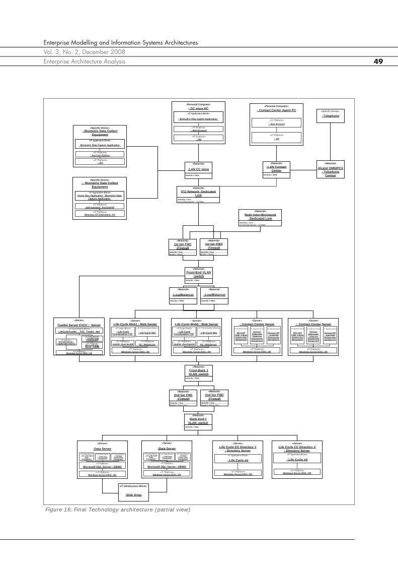
Figure 15 presents the PoC technology architectureand Figure 16 presents a partial view on the finaltechnology architecture. The technological security ofboth architectures are estimated using the SCBITABF(Security Components Between «IT ApplicationBlock» Factor) metric.
013
131
»«#
»«#1)(
»«#
1
ServiceIS
i
inIntegratioServiceIT
ServiceISPoCDTISSF
1,010
1
20
181
»«#
»«#1)(
»«#
1
ServiceIS
i
inIntegratioServiceIT
ServiceISFinalDTISSF
Figure 13:Sequence diagram for the Get Citizen Card Process of the final ISA
SI Ciclo de Vida SI JustiçaFSC SI Finanças SI Seg. SocialSI Saúde SI STAPE
Check Card Status: ()
()Present Data On Chip
Send activation commands to CC middleware: ()Start authentication activation: ()
PIN sign: ()
Test Signature
Start Card Activation:
Authentication certificate activation request: Activate Authentication
Activate EMV-CAPActivate EMV-CAP: CCActivarAutenticacao
SI PKI SI EMV-CAP
Citizen pretends to revoke signature certificate
StartSignature Certificate Revoke: ()CCRevogakeSignatureCertificate
CCRevokateSignatureRevokeSignatureCertificate
RevokeSignature
Check ResultMatch-on-card
Check MatchOnCard
Notify Card new status: CCNotificarEstadoCartaoCCNotififyCardStatus
CCNotififyCardStatus
CCNotififyCardStatus
CCNotififyCardStatus
CCNotififyCardStatus
SI Personalização
CCNotififyCardStatusDeliver Card to Citizen
Activate Digital Signature: Activate Signature
CivilIDSendFingerPrintCheckResult
«Business Service»
:Electronic Signature Activation
«Business Service»
:Test Card Functionaliti
es
«Business Service»
: Verify and activate Card
«Business Service»
:Verify authorization
to provide the card
: Get Citizen Card
«Process»
CheckCardStatus:
Confirm Data on CardRequest Confimation of Card Data
Start Card Activation: ()
Ask Citizen to PIN Code: ()
Insert signature PIN
Check MatchOnCard: ()
Check result
If MatchOnCard is successful proceed to Card delivery
Delivery Cancel: (){OR}
«IS Block»: CC Life Cycle IS
«IS Block»: Personaliza-
tion IS
«IS Block»
:CSF
«IS Block»
: Civil ID IS
«IS Block»
: Finance IS«IS Block»
: Health IS
«IS Block»
: Social Security ISl
«IS Block»
: Voters IS
«IS Block»
: PKI IS
«IS Block»
: OTP IS

Enterprise Modelling and Information Systems ArchitecturesVol. 3, No. 2, December 2008Enterprise Architecture Analysis 47
Therefore the (technological) security in the final ISAis considerable higher than in the PoC ISA.
The reliability of the architectures is estimated usingthe ITRF (IT Redundancy Factor) metric. Consideringthat in the PoC only two «IT Block» present redundantcharacteristics, the ITRF value is:
In the final ISA, since most of the servers have redun-dant characteristics the ITRF value is:
The architectures efficiency was estimated using theSITPLBF (Stateful «IT Presentation Block» and «ITLogic Block» Factor) metric. However, since the pres-entation and logic components of both architecturesdo not keep the state (the state is only managed bythe data components), both architectures presentmaximum values for this metric.
The portability of each ISAs was estimated using thePOSF (Possible Operating Systems Factor) metric.
317,08227
702
»«#»«#
}{#
)(
#
1
»«#
1
ITBlockBlocknApplicatioIT
SITBMin
PoCSCBITABF
BlocknApplicatioIT
i
BlocknApplicatioIT
j
ij
766,0448108
37054
»«#»«#
}{#
)(
#
1
»«#
1
ITBlockBlocknApplicatioIT
SITBMin
FinalSCBITABF
BlocknApplicatioIT
i
BlocknApplicatioIT
j
ij
024,082
2
»«#
#)(
BlockIT
RITBPoCITRF
181,0448
81
»«#
#)(
BlockIT
RITBFinalITRF
11
01
»«#»Pr«#
#1)(SITPLBF
LogicBlockITBlockesentationIT
SITPLBPoC
18
01
»«#»Pr«#
#1)(SITPLBF
LogicBlockITBlockesentationIT
SITPLBFinal
790,0119
251
»«#1)(
»«#
1
BlocknApplicatioIT
i
iNPOS
BlocknApplicatioITPoCPOSF
815,0275
511
»«#1)(
»«#
1
BlocknApplicatioIT
i
iNPOS
BlocknApplicatioITFinalPOSF
Figure 14:Dependencies between application and technological components (CC Life Cycle IS) for the PoC (a) and final (b) ISA
«IS Block»
CC Life Cycle IS
«IS Service»Process Status
«IT Service» Process Status
webService
CC Life Cycle Data Component
«IT Data Block»
CC Life CycleApplication
«IT Application Block»
isTechnologySupported = truesecurityElement = falseredundantElement = falseimplementationParadigm = {Query-Relational}programingLanguage = {“SQL”}possibleOperatingSystems= {Windows}state = {stateful}
isTechnologySupported = truesecurityElement = falseredundantElement = falseimplementationParadigm = {OO}programingLanguage = {“.NET”}possibleOperatingSystems= {Windows}state = {stateful}
«IS Block»
CC Life Cycle IS
«IS Service»Process Status
«IS Service»
Cancel Card
«IT Service»Process Status
webService
«IT Service»
Cancel Card webService
Biometric Data Applet Application
«IT Application Block»
CC Life Cycle Data Component
«IT Data Block»
CC Life Cycle Site
«IT Presentation Block»
CC Life Cycle Coordenation CSF
«IT Logic Block»
isTechnologySupported = truesecurityElement = falseredundantElement = falseimplementationParadigm = {Query-Relational}programingLanguage = {“SQL”}possibleOperatingSystems= {Windows}state = {stateful}
isTechnologySupported = truesecurityElement = falseredundantElement = falseimplementationParadigm = {OOl}programingLanguage = {“Java”}possibleOperatingSystems= {Windows, Linux, Mac, UNIX}state = {statefull}
isTechnologySupported = truesecurityElement = falseredundantElement = falseimplementationParadigm = {OO}programingLanguage = {“ASP”}possibleOperatingSystems= {Windows}state = {stateless}
isTechnologySupported = truesecurityElement = falseredundantElement = falseimplementationParadigm = {OO}programingLanguage = {“.NET”}possibleOperatingSystems= {Windows}state = {stateless}
(a)
(b)

Enterprise Modelling and Information Systems ArchitecturesVol. 3, No. 2, December 2008
André Vasconcelos, Pedro Sousa, José Tribolet48
Figure 15:PoC Technology architecture
P G S S Q L : D a t a S e r v e r
« S e r v e r »
: C C L i f e C y c le D a t a C o m p o n e n t
« IT D a ta B lo c k »
M ic r o s o f t S Q L S e r v e r : D B M S« IT P la t fo r m »
: s w i t c h / f i r e w a l l
« N e t w r o k »
s e c u r i t y = t r u e
P G S D C : D i r e c t o r y S e r v e r« S e r v e r »
: P e g a s u s A D
« IT A p p l ic a t io n B lo c k »
W in d o w s S e r v e r 2 0 0 3 : O S« IT P la t f o r m » W in d o w s S e r v e r 2 0 0 3 : O S
« IT P la t fo r m »
: C a r d S t o r e P C« P e r s o n a l C o m p u t e r »
W in d o w s X P : O S« IT P la t f o r m »
: C C l i f e C y c l e A p p l i c a t io n« I T A p p l ic a t io n B lo c k »
: B io m e t r ic D a t a C o l le c t E q u ip m e n t
« S p e c i f ic D e v ic e »
: O S« IT P la t f o r m »
: B io m e t r ic D a t a C a p t u r e A p p l ic a t i o n
« IT A p p l i c a t io n B lo c k »
: R u n T im e P la t fo r m« IT P la t f o r m »
P G S B T S : F S C S e r v e r« S e r v e r »
: C S F _ B u s in e s s M o d e l l in g , In t e g r a t io n , C o o r d i n a t io n a n d W e b S e r v ic e s
« IT C o o r d in a t io n B lo c k »
B iz T a lk S e r v e r : A p p l i c a t io n S e r v e r« IT P la t f o r m »
W in d o w s S e r v e r 2 0 0 3 : O S« IT P la t f o r m »
: In t e r o p e r a b i l i t y D a ta C o m p o n e n t
« IT D a ta B lo c k »
P G S B E A : S e r v e r« S e r v e r »
W in d o w s 2 0 0 3 S e r v e r : O S« IT P la t f o r m »
: F in a n c e A p p
« I T A p p l ic a t io n B lo c k »
B E A : A p p l ic a t io n S e r v e r
« IT P la t fo r m »
: F in a n c e B D
« I T D a t a B lo c k »
S Q L S e r v e r : D B M S« IT P la t fo rm »
S T A P E S I : S e r v e r« S e r v e r »
W in d o w s 2 0 0 3 S e r v e r : O S« IT P la t fo r m »
: V o t e r A p p
« I T A p p l ic a t io n B lo c k »
.N e t F W : F r a m e w o r k
« IT P la t fo r m »
: V o te r l D B
« IT D a t a B lo c k »
S Q L S e r v e r : D B M S« IT P la t fo r m »
S E G S O C IA L : S e r v e r« S e r v e r »
W in d o w s 2 0 0 3 S e r v e r : O S« IT P la t fo r m »
: S o c ia l S e c u r i t y A p p
« I T A p p l ic a t io n B lo c k »
S u n J a v a S y s t e m : J 2 E E A p p l ic a t io n S e r v e r
« IT P la t fo rm »
: S o c ia l S e c u r i t y D a t a C o m p o n e n t
« I T D a t a B lo c k »
O r a c le D B : D B M S« IT P la t fo r m »
ID C IV IL S I : S e r v e r« S e r v e r »
L in u x R e d H a t : O S« IT P la t f o r m »
: C i v i l ID
« I T A p p l ic a t io n B lo c k »
O u t s y s t e m s H u b S e r v e r 2 : J 2 E E
A p p l ic a t io n S e r v e r
« IT P la t fo rm »
: C iv i l ID D B
« I T D a t a B lo c k »
O r a c le D B : D B M S« IT P la t fo r m »
A D S I G C A : S e r v e r« S e r v e r »
W in d o w s 2 0 0 3 S e r v e r : O S« IT P la t fo r m »
: C A a s s in a t u r a
« I T A p p l ic a t io n B lo c k »
I IS : W e b S e r v e r« I T P la t fo rm »
: C A A s s in a t u r a D B
« I T D a ta B lo c k »
S Q L S e r v e r : D B M S« IT P la t fo r m »
A D A U T C A : S e r v e r« S e r v e r »
W in d o w s 2 0 0 3 S e r v e r : O S« IT P la t f o r m »
: C A A u t h e n t ic a t io
n
« I T A p p l ic a t i o n B lo c k »
I IS : W e b S e r v e r« IT P la t fo r m »
: C A A u t h e n t ic a t io n
D B
« IT D a ta B lo c k »
S Q L S e r v e r : D B M S« IT P la t fo r m »
R o o t C A : S e r v e r« S e r v e r »
L in u x : O S« IT P la t fo r m »
: C A r o o t C C
« IT A p p l ic a t io n B lo c k »
J B o s s : J 2 E E A p p l ic a t io n S e r v e r
« IT P la t fo r m »
: C A r o o t D B
« I T D a ta B lo c k »
P o s t g r e s q l : D B M S« IT P la t fo r m »
.N e t F W : F r a m e w o r k« IT P la t fo r m »
P e r s o n a l i z a t io n : S e r v e r« S e r v e r »
W in d o w s 2 0 0 3 S e r v e r : O S« IT P la t f o r m »
: P e r s o n a l iz a t io n IS
« I T A p p l ic a t io n B lo c k »
: A p p l ic a t io n S e r v e r« IT P la t fo r m »
: P e r s o n a l iz a t io n D B
« IT D a t a B lo c k »
S Q L S e r v e r : D B M S« IT P la t fo r m »
:O T P
« IT A p p l ic a t io n B l o c k »
H E A L T H : S e r v e r« S e r v e r »
W in d o w s 2 0 0 3 S e r v e r : O S« IT P la t f o r m »
: H e a l t h A p p
« IT A p p l ic a t io n B lo c k »
S u n J a v a S y s t e m : J 2 E E A p p lic a t io n S e r v e r
« IT P la t fo r m »
: H e a l t h D a t a C o m p o n e n t
« IT D a t a B lo c k »
O r a c le D B : D B M S« I T P la t fo r m »
P G S C R M : C R M S e r v e r« S e r v e r »
: C i t i z e n R e la t io n s h ip M a n a g e m e n t
« IT A p p l ic a t io n B lo c k »
W in d o w s S e r v e r 2 0 0 3 : O S« IT P la t fo r m »
: C R M D a t a C o m p o n e n t
« IT D a ta B lo c k »
: C o n t a c t C e n t e r A g e n t P C« P e r s o n a l C o m p u t e r »
: O S« IT P la t fo r m »
: W e b B r o w s e r
« IT P la t fo r m »
Enterprise Modelling and Information Systems ArchitecturesVol. 3, No. 2, December 2008Enterprise Architecture Analysis 49
Figure 16:Final Technology architecture (partial view)
Life Cycle Web1 : Web Server«Server»
: Life Cycle Site
«IT Presentation Block»
Windows Server 2003 : OS«IT Platform»
:Data Server
«Server»
: CC Life Cycle Data
Component
«IT Data Block»
Microsoft SQL Server : DBMS«IT Platform»
1st tier FW2 :Firewall
«Netwrok»
security = trueBrand = “Nokia”
1st tier FW1 :Firewall
«Netwrok»
security = trueBrand = “Nokia”
:LoadBalancer
«Netwrok»
security = false
:LoadBalancer
«Netwrok»
security = false
Front-End VLAN :switch
«Netwrok»
security = false
Front-Back 1 VLAN :switch
«Netwrok»
security = false
2nd tier FW2 :Firewall
«Netwrok»
security = trueBrand = “Cisco - Pix””
2nd tier FW1 :Firewall
«Netwrok»
security = trueBrand = “Cisco - Pix”
Back-End 1 VLAN :switch
«Netwrok»
security = false
:Disk Array
«IT Infrastructure Block»
Life Cycle CC Directory 1 : Directory Server
«Server»
: Life Cycle AD
«IT Application Block»
Life Cycle CC Directory 2 : Directory Server
«Server»
: Life Cycle AD
«IT Application Block»
IIS : WebServer«IT Platform»
.NetFW : RunTimeFW«IT Platform»
: Life Cycle Coordenation CSF
«IT Logic Block»
Life Cycle Web2 : Web Server«Server»
: Life Cycle Site
«IT Presentation Block»
Windows Server 2003 : OS«IT Platform»
IIS : WebServer«IT Platform»
: Life Cycle Coordenation CSF
«IT Logic Block»Toolkit Server CVCC : Server
«Server»
LifeCycleToolkit : FSC_Toolkit_.Net«IT Coordination Block»
BizTalk Server : Application Server
«IT Platform»
ITIJ Network :Dedicated Link
«Netwrok»
security = falseprocessingCapacity = 10 Mbps
Rede Inter-Ministerial :Dedicated Link
«Netwrok»
security = falseprocessingCapacity = 10 Mbps
Windows Server 2003 : OS«IT Platform»
Windows Server 2003 : OS«IT Platform»
Windows Server 2003 : OS«IT Platform» Windows Server 2003 : OS
«IT Platform»
: CC store PC«Personal Computer»
: OS«IT Platform»
: Web Browser«IT Platform»
: Biometric Data Applet Application
«IT Application Block»
:LAN CC store
«Netwrok»
security = false
: Biometric Data Collect Equipment
«Specific Device»
Windows XP Embedded : OS«IT Platform»
Vision-Box Application :Biometric Data Capture Application
«IT Application Block»
.NetFW : RunTimeFW«IT Platform»
.NetFramework : RunTimeFW«IT Platform»
: Biometric Data Collect Equipment
«Specific Device»
: OS«IT Platform»
:Biometric Data Capture Application
«IT Application Block»
: RunTime Platform«IT Platform»
: Toolkit Data Component
«IT Data Block»
Microsoft SQL Server : DBMS«IT Platform»
: Contact Center Server«Server»
Genesys IVR : Automatic RelationshipManagement
«IT Application Block»
Windows Server 2003 : OS«IT Platform»
Genesys Multimedia: Telephone
RelationshipManagement
«IT Application Block»
Microsoft CRM : Citizen Relationship Management
«IT Application Block»
: Contact Center Server«Server»
Genesys IVR : Automatic RelationshipManagement
«IT Application Block»
Windows Server 2003 : OS«IT Platform»
Genesys Multimedia: Telephone
RelationshipManagement
«IT Application Block»
Microsoft CRM : Citizen Relationship Management
«IT Application Block»
: CRM Data Component
«IT Data Block»: Contact
Center Data Component
«IT Data Block»
:Data Server
«Server»
: CC Life Cycle Data
Component
«IT Data Block»
Microsoft SQL Server : DBMS«IT Platform»
Windows Server 2003 : OS«IT Platform»
: CRM Data Component
«IT Data Block»: Contact
Center Data Component
«IT Data Block»
:LAN Contact Center
«Netwrok»
security = false
: Contact Center Agent PC«Personal Computer»
: OS«IT Platform»
: Web Browser
«IT Platform»
: Telephone«Specific Device»
Alcatel OMNIPCX : Telephone
Central
«Netwrok»

Enterprise Modelling and Information Systems ArchitecturesVol. 3, No. 2, December 2008
André Vasconcelos, Pedro Sousa, José Tribolet50
In order to estimate the information-technologyalignment the LLIEITBDTMF (Low Level InformationEntity – IT Block Data Type Mismatch Factor) metricwas computed.
Since in the PoC no data was kept for statistics, or au-diting, no low level information entities for managingderived data existed (like the consecutive addressesor consecutive cards for each citizen). As this wasmandatory in the final ISA – and these derived enti-ties are managed by the same applications responsi-ble for managing the primitive entities – amisalignment between the information and technolo-gy levels of the final ISA exists.
Finally, the application-technology alignment wascomputed using the CSTMF (Critical System - Tech-nology Mismatch Factor) metric. However, since allthe processes in this project were considered critical(in both ISAs) the CSTMF presents a maximum valuefor both ISAs.
4.3.5 Alternative ISAs Evaluation
In order to perform a cost-benefit analysis on the PoCand final ISAs, the cost for each architectural levelwas computed. Thus, at information level the NE(Number of Entities) metric values are: NE (PoC) = 8,NE (final) = 10; for the application architecture the NA(Number of Applications) metric values are: NA(PoC)=10, NA (final)=12; and for the technology ar-chitecture the NITB (Number of IT Blocks) metric val-ues are: NITB (PoC)=75, NITB (final)=448.
Combining the cost metrics with the benefit estima-tion metrics (computed in previous subsections) acost-benefit analysis can be performed – in Figure 17this analysis is carried out for the application architec-ture. The final application architecture is estimated to
have higher quality characteristics than the PoC, ex-cept regarding changeability (at application level).
The technological qualities characteristics are alsocompared in Figure 18. The final technological archi-tecture qualities are estimated to be superior to thePoC ones, excepted for the information/technologyalignment (as explained in previous subsection).
Considering the influence of each metric on each qual-ity (previously defined in Table 2), the architecturalqualities, for each ISA, are compared in Figure 19.The Functionality, Reliability, Maintainability and Port-ability are higher in the final ISA than in the PoC. TheEfficiency, according to the metrics, is similar in bothISAs. Finally, the Alignment is estimated to be supe-rior on the PoC ISA, since (as discussed in the previ-ous subsection) no derived information entities wereconsidered on the PoC ISA – however for the produc-tion (final) system this was a mandatory requirement(namely for process security and statistical reasons).Thus, the separation in different technological compo-nents, for the final ISA, is being considered for im-proving the final ISA quality.
112
01(PoC)FLLIEITBDTM
»«#
}{#
»«#
}{#1(PoC)FLLIEITBDTM
ntityformationELowLevelIn
ITBlockntityformationELowLevelIn
ntityformationELowLevelIn
ITBlockntityformationELowLevelIn
NDD
NPP
29,024
171(final)FLLIEITBDTM
»«#
}{#
»«#
}{#1(final)FLLIEITBDTM
ntityformationELowLevelIn
ITBlockntityformationELowLevelIn
ntityformationELowLevelIn
ITBlockntityformationELowLevelIn
NDD
NPP
110
01)(
»«#
}{#}{#1)(
PoCCSTMF
ISBlock
ITBlockISBlockITBlockISBlockPoCCSTMF CNCNCC
112
01)(
»«#
}{#}{#1)(
FinalCSTMF
ISBlock
ITBlockISBlockITBlockISBlockFinalCSTMF CNCNCC
Figure 17:Application architecture Cost-Benefit analysis
Cost-Benefit Analysis for the Application and Information qualities
0
2
4
6
8
10
12
14
0% 20% 40% 60% 80% 100%
Benefit
Cos
t
SuitabilitySecurity (Information and Application)Analyzability Changeability (Application/Information)Changeability (Application)TestabilityBusiness/System AlignmentInformation/Application Alignment
Figure 18:Technological qualities comparativeanalysis
0% 20% 40% 60% 80% 100%
Technical Interoperability
Security (Technological)
Fault tolerance (Reliability)
Resource behavior (Efficiency)
Adaptability (Portability)
Information/Technology Alignment
Application/Technology Alignment
Comparative Analysis of the Tecnological qualities
Final ISA PoC ISA

Enterprise Modelling and Information Systems ArchitecturesVol. 3, No. 2, December 2008Enterprise Architecture Analysis 51
Considering for each quality its relative weight in theglobal ISA quality, in Table 3 is assessed the totalquality of the final and PoC ISAs. Thus, the final ISApresents a total quality superior than the PoC ISA (of65% and 59%, respectively).
Figure 20 presents a cost-benefit analysis of the topqualities (the cost was normalized in the scale [0;1]considering similar weights for each architectural lev-el – information, application and technology).
As a final remark on this case study, it is important toemphasis that this approach, besides demonstratingthat the final ISA quality is higher than the PoC archi-tecture (something that was expected by the projectteam), pointed out some improvement opportunitiesfor the final ISA. Namely, this evaluation revealedthat the final ISA could improve its semantic interop-erability and information-technology alignment.
The semantic interoperability improvements wouldimply some normalization on the information entitiesformats of the different public agencies involved (e.g.,the address format is different in most of the existingsystems). In order to improve the information-tech-
nology alignment the primitive and derived datashould be managed by different IT Blocks (e.g., sep-aration in different IT components of the change ofaddress process and the previous citizen addresses).
5 Conclusion and Future Work
This paper proposes a set of 16 metrics to assess 6ISs’ qualities (adapted and extended from theISO9126 software quality standard), namely: Func-tionality, Reliability, Efficiency, Maintainability, Porta-bility, and Alignment. The metrics, supported in theCEOF UML profile, are also formal defined in OCL (OCLdescription is not presented in the paper for spacelimitations), avoiding any interpretation or applicationambiguities.
The results support that: 1) the metrics are applicablesince the early stages of the ISA definition; 2) themetrics proposed are able to correctly order the ISA,according to the selected qualities; 3) the metrics areindependent of the ISA size - for example, in the Cit-izen Card project the PoC and the final architectureshave very dissimilar sizes (namely the technology ar-chitectures) but it was possible to compare the differ-ent architecture qualities (without being influenced bythe ISA dimension); 4) the metrics do not considerthe possible effort of changing an existing reality –they just assess the “best” ISA, independently of theexisting ISs – for example in the Citizen Card projectthe metric DIIEF (Different Implementations of Infor-mation Entity Factor) revealed this fact.
Using the CEOF architectural primitives and metrics itis described an exploratory approach for supportingthe ISA definition process. This approach, combinesSpewak EAP methodology [SpHi92], with the CEOF
Figure 19:Comparative Analysis of PoC and Final ISAs’ qualities
0% 20% 40% 60% 80% 100%
Functionality
Reliability
Efficiency
Maintainability
Portability
Alignment
Comparative Quality Analysis
ISA Final ISA PoC
Metric Quality Weight ISA PoC ISA finalFunctionality 26% 51.4% 76.5%
Suitability BSRPF 36% 56% 100%Semantic Interoperability DIIEF 12% 67% 42%Technical Interoperability DTISSF 12% 0% 10%Security 40% 58% 86%
Technological SCBITABF 62% 32% 77%Information Application IASF 38% 100% 100%
Reliability ITRF 15% 2.4% 18.1%
Efficiency SITPLBF 12% 100.0% 100.0%
Maintainability 18% 45.9% 46.4%Analyzability SCCF 17% 17% 20%Changeability 39% 71% 69%
Information Application LCOISF 50% 99% 100%Application NOISF 50% 43% 39%
Testability RSF 44% 35% 36%
Portability POSF 9% 79.0% 81.5%
Alignment 21% 89.3% 73.3%Business/System Alignment CPSMF 25% 100% 100%Information/Application Alignment NAIEF 25% 57% 63%Information/Technology Alignment LLIEITBDTMF 25% 100% 30%Application/Technology Alignment CSTMF 25% 100% 100%
Total (ISA Quality) 59% 65%
Table 3: Global evaluation table for the Final and PoC architectures
Figure 20:Global Cost-Benefit analysis
Global Cost-Benefit Analysis
0%10%20%30%40%50%60%70%80%90%
100%
0% 20% 40% 60% 80% 100%
Benefit
Cos
t
Functionality Reliability
Efficiency Maintainability
Portability Alignment
ISA Quality (Total Benefit)

Enterprise Modelling and Information Systems ArchitecturesVol. 3, No. 2, December 2008
André Vasconcelos, Pedro Sousa, José Tribolet52
primitives and defines clear evaluation tasks, usingthe metrics proposed.
Currently we are performing further experimental re-search, in order to verify the independence betweenthe metrics described. Another future research topicis the experimental verification of the correlation be-tween the metrics and the estimated ISA qualities.
Improving the metrics in order to consider/assessother ISA patterns (“best practices”) in the metricsformulas’, is another planned future research path.The approach for constructing an ISA should also beapplied to several more projects and organizations inorder to validate and generalize it.
Finally, another projected work is the improvement ofthe existing software tools for ISA modelling and as-sessment. We plan to integrate ISA monitoring activ-ities (using the CEOF primitives and metrics) on theregular organizational tasks, by providing softwaremonitoring tools for determining the current ISA (inreal time) at technology, application and informationlevels.
6 Acknowledgements
The case study research presented in this paper waspossible thanks to the support of AMA – Agency forthe Public Services Reform.
References
[AbCa94] Abreu, F.; Carapuca, R.; Candidate metrics forobject-oriented software within a taxonomy framework,J. Syst. and Software 23, 87-96, 1994.
[BaBM96] Basili, V. R.; Briand, L. C.; Melo, W. L.; A valida-tion of object-oriented design metrics as quality indica-tors; In: IEEE Trans. Software Eng. 22, 1996.
[BEA06] BEA; Scaling EJB Applications; available in http://edocs.bea.com/wle/tuning/tsejb.htm, May 2006.
[Boar99] Boar, B.: Constructing Blueprints for Enterprise ITArchitecture, John Wiley & Sons, 1999.
[ChKe94] Chidamber, S.; Kemerer, C.; A metrics suite forobject-oriented design. IEEE Trans. on Software Engi-neering, 20(6):476–493, 1994.
[DeMa82] De Marco, T.; Controlling software projects, Your-don Press, New York, 1982.
[ErPe00] Eriksson, H.; Penker, M.: Business Modeling withUML: Business Patterns at Work, John Wiley & Sons,ISBN 0-471-29551-5, 2000.
[Hend96] Henderson-Sellers, B.; Object-Oriented Metrics –Measures of Complexity, The Object-Oriented Series,Prentice Hall PTR, EUA, ISBN 0-13-239872, 1996.
[IDAB03] IDABC; The European Interoperability Framework- for improved pan-European government e-services;Interoperable Delivery of European eGovernment Serv-ices to public Administrations, Business and Citizens,June 2003, available in http://ec.europa.eu/idabc/en/document/1439
[Inmo00] Inmon, W.H.; “Using The Generic Data Model”,White Paper, 2000, http://www.inmoncif.com/library/whitepapers/
[Inmo92] Inmon, W. H; Data architecture: the informationparadigm; QED Information Sciences, Inc. Wellesley,MA, USA, 1992.
[ISO01] ISO 9126, “Information Technology – SoftwareProduct Evaluation – Software Quality Characteristicsand Metrics”, International Organization for Standardi-zation, 2001.
[KhHo04] Khaddaj, S.; Horgan, G.; The Evaluation of Soft-ware Quality Factors in Very Large Information Sys-tems; In: The Electronic Journal of Information SystemEvaluation, Vol.7, Issue 1, 2004.
[McCa76] McCabe, T.J.; A complexity measure, IEEE Trans-actions on Software Engineering, SE-2, Volume 4,1976, pp. 308-320.
[MCL+99] Malone, T.; Crowston, K.; Lee J.; et al.,: Tools forinventing organizations: Towards a handbook of organi-zational processes, Management Science, 1999.
[MRTG00] Maes, R.; Rijsenbrij, D.; Truijens, O.; Goedvolk,H.; Redefining Business – IT Alignment Through a Uni-fied Framework, White Paper, May 2000, http://www.cs.vu.nl/~daan/
[OMG06a] OMG, “Unified Modeling Language: Superstruc-ture, version 2.1”, Object Management Group, 2006.
[OMG06b] OMG, “Object Constraint Language: OMG Availa-ble Specification Version 2.0”, Object ManagementGroup, 2006.
[OpGr03] Open Group; The Open Group Architectural Frame-work (TOGAF) – Version 8.1, chapter 19, December2003.
[SaSu03] Sarkis, J.; Sundarraj, R.; Evaluating Componen-tized Enterprise Information Technologies: A Multiat-tribute Modeling Approach, Information SystemsFrontiers, Kluwer Academic Publishers, 2003, section3.2.1, pp. 303–319.
[SoPM04] Sousa. P.; Pereira, C.; Marques, J.; EnterpriseArchitecture Alignment Heuristics, Journal4, MicrosoftArchitects Journal , October 2004.
[SpHi92] Spewak, S.; Hill, S.; Enterprise Architecture Plan-ning: Developing a Blueprint for Data, Applications andTechnology, Wiley-QED, ISBN 0-471-599859, 1992.
[STV+06] Sousa, P,; Tribolet, J.; Vasconcelos, A.; Caetano,A.; Pereira, C.; Enterprise Modeling and Computing withUML, chapter of book “Enterprise Modeling and Com-puting with UML” edited by Peter Rittgen, UniversityCollege Borås, Sweden, ISBN: 1-59904-175-8, 2006
[Varg00] Vargas, H.; High Availability Fundamentals, SunBluePrints OnLine, November 2000, available inhttp://www.sun.com/blueprints/1100/HAFund.pdf

Enterprise Modelling and Information Systems ArchitecturesVol. 3, No. 2, December 2008Enterprise Architecture Analysis 53
[Vasc06] Vasconcelos, A.; CEO Framework for InformationSystem Architecture: An UML profile, CEO Report, avail-able at http://ceo.inesc.pt/andre/reports/CEOF_UML_Profile_v1_2.pdf
[VaST03] Vasconcelos, A.; Sousa, P.; Tribolet, J.; Informa-tion System Architectures; In: Proceedings of BusinessExcelence 2003, International Conference on Perform-ance Measures, Benchmarking and Best Practices inNew Economy, Portugal, June 2003.
[VaST05] Vasconcelos, A.; Sousa, P., Tribolet, J.; Informa-tion System Architecture Evaluation: From Software toEnterprise Level Approaches; In: 12th European Con-ference On Information Technology Evaluation (ECITE2005), Turku, Finland, September 2005.
[VCN+01] Vasconcelos, A.; Caetano, A,; Neves, J.; Sinogas,P.; Mendes, R; Tribolet, J.: A Framework for ModelingStrategy, Business Processes and Information Systems;In: 5th International Enterprise Distributed ObjectComputing Conference EDOC, Seatle, USA, September2001.
[VSFT04] Vasconcelos, A.; Silva,M; Fernandes, A.; Tribolet.,J.; An Information System Architectural Framework forEnterprise Application Integration; In: Proceedings of37th Annual Hawaii International Conference On Sys-tem Sciences (HICCS37), Hawaii, USA, 2004.
[Zach97] Zachman, J.: Enterprise Architecture: The Issue ofthe Century, Database Programming and Design, March1997, pp. 11.
[Zach99] Zachman, J.: Enterprise Architecture: The Past andthe Future”. In: DM Review Magazine, December 1999.
André Vasconcelos, Pedro Sousa, José Tribolet
Instituto Superior Técnico, Technical University of LisbonCEO - Centro de Engenharia Organizacional - INESC Rua Alves Redol 9LisbonPortugal{andre.vasconcelos|pedro.sousa|jose.tribolet}@dei.ist.utl.pt