enterprise campus design: routed...
TRANSCRIPT

© 2012 Cisco and/or its affiliates. All rights reserved. BRKCRS-3036 Cisco Public
Enterprise Campus Design:
Routed Access
BRKCRS-3036
2

© 2012 Cisco and/or its affiliates. All rights reserved. BRKCRS-3036 Cisco Public
Some Loops are Fun ...
5

© 2012 Cisco and/or its affiliates. All rights reserved. BRKCRS-3036 Cisco Public
But Not All ... Sounds Familiar...?
“The whole network is down”
“Nothing seems to work”
“I can’t access anything”
“All systems are unreachable”
Many of us have suffered the consequences of a L2 loop
%IP-4-DUPADDR: Duplicate address 10.87.1.2 on Vlan100, sourced by 00d0.04e0.63fc %IP-4-DUPADDR: Duplicate address 10.87.1.2 on Vlan100, sourced by 00d0.04e0.63fc %IP-4-DUPADDR: Duplicate address 10.87.1.2 on Vlan100, sourced by 00d0.04e0.63fc ...
%C4K_EBM-4-HOSTFLAPPING: Host 00:02:A5:8A:8B:5E in vlan 60 is flapping between port Gi3/6 and port Po9 %C4K_EBM-4-HOSTFLAPPING: Host 00:02:A5:8A:8B:5E in vlan 60 is flapping between port Gi3/6 and port Po9 %C4K_EBM-4-HOSTFLAPPING: Host 00:02:A5:8A:8B:5E in vlan 60 is flapping between port Gi3/6 and port Po9 ...
Number of topology changes 2433341 last change occurred 00:00:02 ago
%PM-SP-4-LIMITS: Virtual port count for module 5 exceeded the recommended limit of 1800 %PM-SP-4-LIMITS: Virtual port count for switch exceeded the recommended limit of 13000
6

© 2012 Cisco and/or its affiliates. All rights reserved. BRKCRS-3036 Cisco Public
The Problem? One Solution...
L2 Fails Open – i.e. Broadcast
and Unknowns flooded
L3 Fails Closed – i.e. neighbour lost
SiSi SiSi
SiSi
L2 Control Plane Failure
L3 Control Plane Failure
... a loop and a network down
... some subnets down
7

© 2012 Cisco and/or its affiliates. All rights reserved. BRKCRS-3036 Cisco Public
This Is Not About...
This is about ...
A design alternative that leverages L3 routing all the way down to the access layer, to see where it brings an advantage while we analyze the trade offs of using it.
L3 = GOOD L2 = BAD
8
© 2012 Cisco and/or its affiliates. All rights reserved. BRKCRS-3036 Cisco Public
Enterprise Campus Design: Routed Access
Introduction
Cisco Campus Architecture Review
Campus Routing Foundation and Best Practices
Building a Routed Access Campus Design
Routed Access Design and VSS
Routed Access Design for IPv6
Impact of Routed Access Design for Advanced Technologies
Summary
Agenda
9

© 2012 Cisco and/or its affiliates. All rights reserved. BRKCRS-3036 Cisco Public
One Time Zone—Real Time
Borderless Campus 21st Century Business Realities
Rapid Collaborative Decisions
Strict Governance for Compliance and Risk Reduction
Workers, Customers, and Partners Operate Anywhere
Resources Must be Leveraged to Their Maximum
10

© 2012 Cisco and/or its affiliates. All rights reserved. BRKCRS-3036 Cisco Public
Borderless Campus New Users, Applications, Services
Data Center
Campus
SiSi SiSi SiSi SiSi SiSi SiSi
SiSi SiSi
SiSi SiSi
Subcontractor
Consultant
Partners
Employees
Unknown or Guest
Badge Readers
11

© 2012 Cisco and/or its affiliates. All rights reserved. BRKCRS-3036 Cisco Public
Borderless Campus
IP Telephony (IPT) is now a mainstream technology
Ongoing evolution to the full spectrum of Unified Communications
High Definition Video Communications requires stringent
Service-Level Agreement (SLA)
‒ Reliable Service – High Availability Infrastructure
‒ Application Service Management – End-to-End QoS
Collaboration and Video Evolution
12

© 2012 Cisco and/or its affiliates. All rights reserved. BRKCRS-3036 Cisco Public
0.8 sec loss 0.4 sec loss
Stresses and demands of video on the
network expose shortcomings of ‘good
enough’ convergence 1
11
2
1
31
41
51
6
1
71
81
91
10
1
11
1
12
1
13
1
14
1
15
1
16
1
17
1
18
1
19
1
20
1
21
1
22
1
23
1
24
1
25
1
26
1
27
1
28
1
29
1
Traf
fic
(Kb
ps)
Effect of 0.8 sec of Interruption on Diverse Multimedia Traffic
> 1 min
0
100000
200000
300000
400000
500000
600000
0.8 sec
Medianet Application Requirements The Effect of Convergence Times on Media Flows
13

© 2012 Cisco and/or its affiliates. All rights reserved. BRKCRS-3036 Cisco Public
Fast Convergence and Reliability
Are Essential...
14

© 2012 Cisco and/or its affiliates. All rights reserved. BRKCRS-3036 Cisco Public
Enterprise Campus Design: Routed Access
Introduction
Cisco Campus Architecture Review
Campus Routing Foundation and Best Practices
Building a Routed Access Campus Design
Routed Access Design and VSS
Routed Access Design for IPv6
Impact of Routed Access Design for Advanced Technologies
Summary
Agenda
15

© 2012 Cisco and/or its affiliates. All rights reserved. BRKCRS-3036 Cisco Public
Hierarchical Network Design Without a Rock Solid Foundation the Rest Doesn‘t Matter
Building Block WAN Internet
SiSi SiSi SiSi SiSi SiSi SiSi
SiSi SiSi
SiSi SiSi
SiSi SiSiSiSi
SiSi
Access
Distribution
Core
Distribution
Access Offers hierarchy—each layer has specific role
Modular topology—building blocks
Easy to grow, understand, and troubleshoot
Creates small fault domains—clear demarcations
and isolation
Promotes load balancing and redundancy
Promotes deterministic traffic patterns
Incorporates balance of both Layer 2 and Layer 3
technology, leveraging the strength of both
Can be applied to both the multilayer and routed
campus designs
16

© 2012 Cisco and/or its affiliates. All rights reserved. BRKCRS-3036 Cisco Public
L2
Multilayer Campus Network Design Layer 2 Access with Layer 3 Distribution
SiSi SiSi SiSi SiSi
Vlan 10 Vlan 20 Vlan 30 Vlan 30 Vlan 30 Vlan 30
L3
Each access switch has
unique VLAN‘s
No layer 2 loops
Layer 3 link between
distribution
No blocked links
At least some VLAN‘s span
multiple access switches
Layer 2 loops
Layer 2 and 3 running over
link between distribution
Blocked links
17

© 2012 Cisco and/or its affiliates. All rights reserved. BRKCRS-3036 Cisco Public
Multilayer Campus Network Design
Mature, 10+ year old design
Evolved due to historical pressures
‒ Cost of routing vs. switching
‒ Speed of routing vs. switching
‒ Non-routable protocols
Well understood optimization of
interaction between the various
control protocols and the topology
‒ STP Root and HSRP primary tuning to
load balance on uplinks
‒ Spanning Tree Toolkit (RootGuard,
LoopGuard, …)
‒ etc., …
Well Understood Best Practices
SiSi SiSi
SiSi SiSi
BRKCRS-2031 – Multilayer Campus Architectures and Design Principals
Root Bridge &
HSRP Active
HSRP Standby
CISF, BPDU Guard
LoopGuard
RootGuard
18

© 2012 Cisco and/or its affiliates. All rights reserved. BRKCRS-3036 Cisco Public
0
2
4
6
8
10
250 msec 3 secs
Multilayer Campus Network Design
Utilizes multiple Control Protocols
‒ Spanning Tree (802.1w, …)
‒ FHRP (HSRP, VRRP, GLBP…)
‒ Routing Protocol (EIGRP, …)
Convergence is dependent on
multiple factors
‒ FHRP - 900msec to 9 seconds
‒ Spanning Tree - 400msec to
50 seconds
FHRP Load Balancing
‒ HSRP/VRRP – Per Subnet
‒ GLBP – Per Host
Good Solid Design Option
Tim
e t
o r
est
ore
Vo
IP d
ata
flo
ws
(se
con
ds)
HSRP Hello Timers
FHRP Convergence
19

© 2012 Cisco and/or its affiliates. All rights reserved. BRKCRS-3036 Cisco Public
3/2 3/2
3/1 3/1
Switch 1 Switch 2
DST MAC 0000.0000.4444
DST MAC 0000.0000.4444
Multilayer Campus Network Design Layer 2 Loops and Spanning Tree
Campus Layer 2 topology has sometimes proven a operational or
design challenge
Spanning tree protocol itself is not usually the problem, it‘s the external
events that triggers the loop or flooding
L2 has no native mechanism to dampen down a problem:
‒ L2 fails Open, as opposed to L3 which fails closed
Implement Spanning Tree loops only when you have to
20

© 2012 Cisco and/or its affiliates. All rights reserved. BRKCRS-3036 Cisco Public
Enterprise Campus Design: Routed Access
Introduction
Cisco Campus Architecture Review
Campus Routing Foundation and Best Practices
Building a Routed Access Campus Design
Routed Access Design and VSS
Routed Access Design for IPv6
Impact of Routed Access Design for Advanced Technologies
Summary
Agenda
21

© 2012 Cisco and/or its affiliates. All rights reserved. BRKCRS-3036 Cisco Public
Best Practices—Campus Routing Leverage Equal Cost Multiple Paths
Data Center WAN Internet
Layer 3 Equal Cost Link’s
Layer 3 Equal Cost Link’s
SiSiSiSi
SiSiSiSi
SiSi SiSiSiSiSiSi
SiSi SiSi SiSi SiSi SiSi SiSi
Use routed pt2pt links and do not
peer over client VLANs, SVIs.
ECMP to quickly re-route around
failed node/links with load balancing
over redundant paths
Tune CEF L3/L4 load balancing
hash to achieve maximum utilization
of equal cost paths (CEF
polarization)
Build triangles not squares for
deterministic convergence
Insure redundant L3 paths to
avoid black holes
Summarize distribution to core to
limit event propagation
Utilized on both Multi-Layer and
Routed Access designs
22

© 2012 Cisco and/or its affiliates. All rights reserved. BRKCRS-3036 Cisco Public
Routed Interfaces Offer Best Convergence Properties
21:32:47.813 UTC: %LINEPROTO-5-UPDOWN: Line protocol on Interface GigabitEthernet2/1, changed state to down 21:32:47.821 UTC: %LINK-3-UPDOWN: Interface GigabitEthernet2/1, changed state to down 21:32:48.069 UTC: %LINK-3-UPDOWN: Interface Vlan301, changed state to down 21:32:48.069 UTC: IP-EIGRP(Default-IP-Routing-Table:100): Callback: route, adjust Vlan301
1. Link Down
2. Interface Down
3. Autostate
4. SVI Down
5. Routing Update
21:38:37.042 UTC: %LINEPROTO-5-UPDOWN: Line protocol on Interface GigabitEthernet3/1, changed state to down 21:38:37.050 UTC: %LINK-3-UPDOWN: Interface GigabitEthernet3/1, changed state to down 21:38:37.050 UTC: IP-EIGRP(Default-IP-Routing-Table:100): Callback: route_adjust GigabitEthernet3/1
SiSiSiSi
L2
SiSiSiSi
L3 1. Link Down
2. Interface Down
3. Routing Update
~ 8 msec loss
~ 150-200 msec loss
Configuring L3 routed interfaces provides for faster
convergence than a L2 switchport with an associated L3 SVI
23

© 2012 Cisco and/or its affiliates. All rights reserved. BRKCRS-3036 Cisco Public
Best Practice—Build Triangles Not Squares Deterministic vs. Non-Deterministic
Triangles: Link/Box Failure Does Not Require Routing Protocol Convergence
Model A
Squares: Link/Box Failure Requires Routing Protocol Convergence
Model B
SiSi
SiSiSiSi
SiSiSiSi
SiSiSiSi
SiSi
Layer 3 redundant equal cost links provide fast convergence
Hardware based—fast recovery to remaining path
Convergence is extremely fast (dual equal-cost paths: no need for
OSPF or EIGRP to recalculate a new path) 24

© 2012 Cisco and/or its affiliates. All rights reserved. BRKCRS-3036 Cisco Public
0
0.5
1
1.5
2
2.5
3
3.5
500 1000 5000 10000 15000 20000 25000
Co
nve
rgen
ce
(s
ec
)
ECMP ECMP (SXI2) MEC
CEF ECMP—Optimize Convergence ECMP Convergence Is Dependent on Number of Routes
Number or Routes in Area – Sup720
SiSi
SiSi
SiSi
Time for ECMP Recovery
Time for ECMP/MEC Unicast Recovery
Until recently, time to update switch HW FIB was linearly dependent on the number of entries (routes) to be updated
Summarization and Filtering will decrease RP load as well as speed up convergence
25

© 2012 Cisco and/or its affiliates. All rights reserved. BRKCRS-3036 Cisco Public
CEF Load Balancing Underutilized Redundant Layer 3 Paths
Redundant Paths Ignored
SiSiSiSi
SiSi SiSi
SiSi SiSi
L
L
R
R
Distribution Default L3 Hash
Core Default L3 Hash
Distribution Default L3 Hash
Access Default L3 Hash
Access Default L3 Hash
70%
load
30%
load
The default CEF hash ‗input‘ is L3 source and destination IP addresses
• Imbalance/overload could occur
CEF polarization: in a multihop design, CEF could select the same left/left or right/right path
• Redundant paths are ignored/underutilized
Two solutions:
1. CEF Hash Tuning
2. CEF Universal ID
26

© 2012 Cisco and/or its affiliates. All rights reserved. BRKCRS-3036 Cisco Public
SiSiSiSi
SiSi SiSi
SiSi SiSi
CEF Load Balancing 1. Avoid Polarization with CEF Hash Tuning
R L
R Distribution L3/L4 Hash
Core Default L3 Hash
Distribution L3/L4 Hash
L
R L
Left Side Shown
Access Default L3 Hash
Access Default L3 Hash
All Paths Used
L
With defaults, CEF could select the same left/left or right/right paths and ignore some redundant paths
Alternating L3/L4 hash and default L3 hash will give us the better load balancing results
The default is L3 hash—no modification required in core or access
In the distribution switches use:
‒ mls ip cef load-sharing full
to achieve better redundant path utilization
27

© 2012 Cisco and/or its affiliates. All rights reserved. BRKCRS-3036 Cisco Public
CEF Load Balancing 2. Avoid Polarization with Universal ID
Cisco IOS uses ―Universal ID‖ concept (also called Unique ID) to prevent CEF polarization
‒ Universal ID generated at bootup (32-bit pseudo-random value seeded by router‘s base IP address)
Universal ID used as input to ECMP hash, introduces variability of hash result at each network layer
Universal ID supported on Catalyst 6500 Sup-32, Sup-720, Sup-2T
Universal ID supported on Catalyst 4500 SupII+10GE, SupV-10GE and Sup6E
Hash using • Source IP (SIP) + • Destination IP (DIP) + • Universal ID
Original Src IP + Dst IP
Universal* Src IP + Dst IP + Unique ID
Include Port Src IP + Dst IP + (Src or Dst Port) + Unique ID
Default* Src IP + Dst IP + Unique ID
Full Src IP + Dst IP + Src Port + Dst Port
Full Exclude Port Src IP + Dst IP + (Src or Dst Port)
Simple Src IP + Dst IP
Full Simple Src IP + Dst IP + Src Port + Dst Port
Catalyst 4500 Load-Sharing Options Catalyst 6500 PFC3** Load-Sharing Options
SiSi SiSi
SiSi SiSi
SiSi
* = Default Load-Sharing Mode
28

© 2012 Cisco and/or its affiliates. All rights reserved. BRKCRS-3036 Cisco Public
Enterprise Campus Design: Routed Access
Introduction
Cisco Campus Architecture Review
Campus Routing Foundation and Best Practices
Building a Routed Access Campus Design
Routed Access Design and VSS
Routed Access Design for IPv6
Impact of Routed Access Design for Advanced Technologies
Summary
Agenda
29

© 2012 Cisco and/or its affiliates. All rights reserved. BRKCRS-3036 Cisco Public
Routed Access Design Layer 3 Distribution with Layer 3 Access: no L2 Loop
Data 10.1.20.0/24
2001:DB8:CAFE:20::/64
Voice 10.1.120.0/24
2001:DB8:CAFE:120::/64
EIGRP/OSPF EIGRP/OSPF
GLBP Model
SiSiSiSi
Layer 3
Layer 2
Layer 3
Layer 2 EIGRP/OSPF EIGRP/OSPF
SiSi SiSi
Data 10.1.40.0/24
2001:DB8:CAFE:40::/64
Voice 10.1.140.0/24
2001:DB8:CAFE:140::/64
Move the Layer 2/3 demarcation to the network edge
Leverages L2 only on the access ports, but builds a L2 loop-free network
Design Motivations: simplified control plane, ease of troubleshooting, high availability
30

© 2012 Cisco and/or its affiliates. All rights reserved. BRKCRS-3036 Cisco Public
Routed Access Advantages Simplified Control Plane
Simplified Control Plane ‒ No STP feature placement (root bridge,
loopguard, …)
‒ No default gateway redundancy setup/tuning (HSRP, VRRP, GLBP ...)
‒ No matching of STP/HSRP priority
‒ No asymmetric flooding
‒ No L2/L3 multicast topology inconsistencies
‒ No Trunking Configuration Required
L2 Port Edge features still apply: ‒ Spanning Tree Portfast
‒ Spanning Tree BPDU Guard
‒ Port Security, DHCP Snooping, DAI, IPSG
‒ Storm Control
‒ 802.1x
‒ QoS Settings ...
SiSi
SiSiSiSi
SiSi
L3 L3 L3 L3
L3
SiSi SiSi
31

© 2012 Cisco and/or its affiliates. All rights reserved. BRKCRS-3036 Cisco Public
Routed Access Advantages Simplified Network Recovery
Routed Access network recovery is
dependent on L3 re-route
Time to restore upstream traffic flows
is based on ECMP re-route
‒ Time to detect link failure
‒ Process the removal of the lost routes from
the SW RIB
‒ Update the HW FIB
Time to restore downstream flows is
based on a routing protocol re-route
‒ Time to detect link failure
‒ Time to determine new route
‒ Process the update for the SW RIB
‒ Update the HW FIB Upstream Recovery: ECMP Downstream Recovery: Routing Protocol
SiSi
SiSiSiSi
SiSi
SiSi SiSi
32

© 2012 Cisco and/or its affiliates. All rights reserved. BRKCRS-3036 Cisco Public
0
0.2
0.4
0.6
0.8
1
1.2
1.4
1.6
1.8
2
RPVST+FHRP
OSPF EIGRP
Upstream
Downstream
Routed Access Advantages Faster Convergence Times
RPVST+ convergence times
dependent on FHRP tuning
‒ Proper design and tuning can
achieve sub-second times
EIGRP converges <200 msec
OSPF converges <200 msec
with LSA and SPF tuning
Both L2 and L3 Can Provide Sub-Second Convergence
SiSiSiSi
SiSi SiSi
33

© 2012 Cisco and/or its affiliates. All rights reserved. BRKCRS-3036 Cisco Public
SiSi
Designated Router
(High IP Address)
IGMP Querier (Low IP address)
Designated Router & IGMP
Querier
Non-DR has to drop all non-RPF
Traffic
SiSiSiSi SiSi
SiSi
Routed Access Advantages A Single Router per Subnet: Simplified Multicast
Layer 2 access has two multicast routers per access subnet, RPF checks
and split roles between routers
Routed Access has a single multicast router which simplifies multicast
topology and avoids RPF check altogether
34

© 2012 Cisco and/or its affiliates. All rights reserved. BRKCRS-3036 Cisco Public
Routed Access Advantages Ease of Troubleshooting
Routing troubleshooting tools
‒ Consistent troubleshooting:
access, dist, core
‒ show ip route / show ip cef
‒ Traceroute
‒ Ping and extended pings
‒ Extensive protocol debugs
‒ IP SLA from the Access Layer
Failure differences
‒ Routed topologies fail closed—i.e.
neighbor loss
‒ Layer 2 topologies fail open—i.e.
broadcast and unknowns flooded
SiSi
SiSiSiSi
SiSi
L3 L3 L3 L3
L3
switch#sh ip cef 192.168.0.0
192.168.0.0/24
nexthop 192.168.1.6 TenGigabitEthernet9/4
35
© 2012 Cisco and/or its affiliates. All rights reserved. BRKCRS-3036 Cisco Public
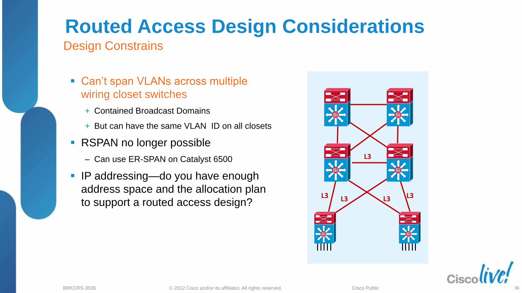
Routed Access Design Considerations Design Constrains
Can‘t span VLANs across multiple
wiring closet switches
+ Contained Broadcast Domains
+ But can have the same VLAN ID on all closets
RSPAN no longer possible
‒ Can use ER-SPAN on Catalyst 6500
IP addressing—do you have enough
address space and the allocation plan
to support a routed access design?
SiSi
SiSiSiSi
SiSi
L3 L3 L3 L3
L3
SiSi SiSi
36

© 2012 Cisco and/or its affiliates. All rights reserved. BRKCRS-3036 Cisco Public
Routed Access Design Considerations Platform Requirements
Catalyst Requirements
‒ Cisco Catalyst 3560 and 3750
‒ Cisco Catalyst 4500
‒ Cisco Catalyst 6500
Catalyst IOS IP Base minimum feature set
‒ EIGRP-Stub – Edge Router
‒ PIM Stub – Edge Router
‒ OSPF for Routed Access
200 Dynamically Learned Routes
Catalyst 3x00 Series IOS 12.2(55)SE
Catalyst 4500 Series IOS 12.2(53)SG
Catalyst 6500 Series IOS 12.2(33)SXI4
SiSi
SiSiSiSi
SiSi
L3 L3 L3 L3
L3
SiSi SiSi
37

© 2012 Cisco and/or its affiliates. All rights reserved. BRKCRS-3036 Cisco Public
Routed Access Design Migrating from a L2 Access Model
DHCP DNS 10.1.20.0/24
10.1.30.0/24
...
10.1.120.0/24
VLAN 20
VLAN 30
...
VLAN 120
EIGRP/OSPF
GLBP Model VLAN 20
VLAN 30
...
VLAN 120
VLAN 20
VLAN 30
...
VLAN 120
20,30 ... 120
User Groups User Groups
interface Vlan20
ip address 10.1.20.3 255.255.255.0
ip helper-address 10.5.10.20
standby 1 ip 10.1.20.1
standby 1 timers msec 200 msec 750
standby 1 priority 150
standby 1 preempt
standby 1 preempt delay minimum 180
interface GigabitEthernet1/1
switchport
switchport trunk encapsulation dot1q
switchport trunk allowed vlan 20-120
switchport mode trunk
switchport nonegotiate
10.5.10.20
SiSiSiSi
SiSiSiSi
Typical deployment uses Vlan/Subnet for different user groups
To facilitate user mobility, vlans extend to multiple closets 38

© 2012 Cisco and/or its affiliates. All rights reserved. BRKCRS-3036 Cisco Public
DHCP DNS
Routed Access Design Migrating from a L2 Access Model
10.1.20.0/24
10.1.30.0/24
...
10.1.120.0/24
VLAN 20
VLAN 30
...
VLAN 120
EIGRP/OSPF
GLBP Model VLAN 20
VLAN 30
...
VLAN 120
VLAN 20
VLAN 30
...
VLAN 120
20,30 ... 120
User Groups User Groups
interface Vlan20
ip address 10.1.20.3 255.255.255.0
ip helper-address 10.5.10.20
standby 1 ip 10.1.20.1
standby 1 timers msec 200 msec 750
standby 1 priority 150
standby 1 preempt
standby 1 preempt delay minimum 180
10.5.10.20
SiSiSiSi
L3
L3 L3
L3 L3
SiSiSiSi
interface GigabitEthernet1/1
description Distribution Downlink
ip address 10.120.0.196 255.255.255.254
interface GigabitEthernet1/1
switchport
switchport trunk encapsulation dot1q
switchport trunk allowed vlan 20-120
switchport mode trunk
switchport nonegotiate
As the routing is moved to the access layer, trunking is no longer required
/31 addressing can be used on p2p links to optimize ip space utilization
39

© 2012 Cisco and/or its affiliates. All rights reserved. BRKCRS-3036 Cisco Public
DHCP DNS
Routed Access Design Migrating from a L2 Access Model
10.1.20.0/24
10.1.30.0/24
...
10.1.120.0/24
VLAN 20
VLAN 30
...
VLAN 120
EIGRP/OSPF
GLBP Model VLAN 20
VLAN 30
...
VLAN 120
User Groups User Groups
interface Vlan20
ip address 10.1.20.3 255.255.255.0
ip helper-address 10.5.10.20
standby 1 ip 10.1.20.1
standby 1 timers msec 200 msec 750
standby 1 priority 150
standby 1 preempt
standby 1 preempt delay minimum 180
10.5.10.20
SiSiSiSi
L3
L3 L3
L3 L3
interface Vlan20
ip address 10.1.20.3 255.255.255.128
ip helper-address 10.5.10.20
10.1.20.0/25
10.1.30.0/25
...
10.1.120.0/25
10.1.20.128/25
10.1.30.128/25
...
10.1.120.128/25
SiSiSiSi
SVI configuration at the access layer is simplified
Larger subnets are split into smaller ones and assigned to new DHCP scopes
40

© 2012 Cisco and/or its affiliates. All rights reserved. BRKCRS-3036 Cisco Public
Enterprise Campus Design: Routed Access
Introduction
Cisco Campus Architecture Review
Campus Routing Foundation and Best Practices
Building a Routed Access Campus Design
‒ EIGRP Design to Route to the Access Layer
‒ OSPF Design to Route to the Access Layer
‒ Other Design Considerations
Routed Access Design and VSS
Routed Access Design for IPv6
Impact of Routed Access Design for Advanced Technologies
Agenda
41

© 2012 Cisco and/or its affiliates. All rights reserved. BRKCRS-3036 Cisco Public
Deploying a Stable and Fast Converging
EIGRP Campus Network
The key aspects to consider are:
1. Using EIGRP Stub at the access layer
2. Route Summarization at the distribution layer
3. Leverage Route filters
4. Consider Hello and Hold Timer tuning
42

© 2012 Cisco and/or its affiliates. All rights reserved. BRKCRS-3036 Cisco Public
EIGRP Neighbors Event Detection
EIGRP neighbor relationships are created when a
link comes up and routing adjacency is established
When physical interface changes state, the routing
process is notified
‒ Carrier-delay should be set as a rule because
it varies based upon the platform
Some events are detected by the
routing protocol
‒ Neighbor is lost, but interface is UP/UP
To improve failure detection
‒ Use routed interfaces and not SVIs
‒ Decrease interface carrier-delay to 0
‒ Decrease EIGRP hello and hold-down timers*
Hello = 1
Hold-down = 3
* Not recommended with NSF/SSO
interface GigabitEthernet3/2
ip address 10.120.0.50 255.255.255.252
ip hello-interval eigrp 100 1
ip hold-time eigrp 100 3
carrier-delay msec 0
SiSiSiSi
Routed Interface
SiSi
SiSi
SiSi
Hellos
L2 Switch or VLAN Interface
43

© 2012 Cisco and/or its affiliates. All rights reserved. BRKCRS-3036 Cisco Public
EIGRP in the Campus Conversion to an EIGRP Routed Edge
The greatest advantages of EIGRP are
gained from the use of summarization and
stub routers
EIGRP allows for multiple tiers of hierarchy,
summarization and route filtering
Relatively painless to migrate to a L3 access
with EIGRP
Deterministic convergence time in very large
L3 topology
EIGRP maps easily to campus topology
10.10.0.0/17 10.10.128.0/17
10.10.0.0/16
SiSi SiSi SiSi SiSi
SiSi SiSi
44

© 2012 Cisco and/or its affiliates. All rights reserved. BRKCRS-3036 Cisco Public
EIGRP Design Rules for HA Campus Limit Query Range to Maximize Performance
EIGRP convergence is dependent on query response times
Minimize the number of queries to speed up convergence
Summarize distribution block routes to limit how far queries propagate across the campus
‒ Upstream queries are returned immediately with infinite cost
Configure access switches as EIGRP stub routers
‒ No downstream queries are ever sent
SiSiSiSi
SiSiSiSi
router eigrp 100
network 10.0.0.0
eigrp stub connected
interface TenGigabitEthernet 4/1
ip summary-address eigrp 100 10.120.0.0 255.255.0.0 5
router eigrp 100
network 10.0.0.0
distribute-list Default out <mod/port>
ip access-list standard Default
permit 0.0.0.0
45

© 2012 Cisco and/or its affiliates. All rights reserved. BRKCRS-3036 Cisco Public
EIGRP Query Process Queries Propagate the Event
EIGRP relies on neighbors to provide
routing information
If a route is lost and no feasible successor is
available, EIGRP actively queries its
neighbors for the lost route(s)
The router waits for replies from all queried
neighbors before the calculating a new path
If any neighbor fails to reply, the queried
route is stuck in active and the router resets
neighbor adjacency
The fewer routers and routes
queried, the faster EIGRP converges;
solution is to limit query propagation SiSiSiSi
Query
SiSiSiSi
SiSiSiSi
Query
Query
Query
Query
Query
Query
Query
Query
Reply
Reply
Reply
Reply
Reply
Reply
Reply
Reply
Reply Access
Distribution
Core
Distribution
Access
46

© 2012 Cisco and/or its affiliates. All rights reserved. BRKCRS-3036 Cisco Public
No Queries to Rest of Network
from Core
Limiting the EIGRP Query Range With Summarization
Summarization from distribution to core
for the subnets in the access
limits the upstream query/reply process
Queries will now stop at the core; no
additional distribution blocks will be
involved in the convergence event
The access layer is still queried
SiSiSiSi
SiSiSiSi
Query Query
Query Reply Reply
Reply
Reply∞ Reply∞
interface gigabitethernet 3/1
ip address 10.120.10.1 255.255.255.252
ip summary-address eigrp 1 10.130.0.0 255.255.0.0
Summary Route
Summary Route
47

© 2012 Cisco and/or its affiliates. All rights reserved. BRKCRS-3036 Cisco Public
Limiting the EIGRP Query Range With Stub Routers
A stub router signals (through hellos)
that it is a stub and not a transit path
Queries are not sent towards the stub
routers but marked as if a ―No path this
direction‖ reply had been received
A stub router signals (through hellos)
that it is a stub and not a transit path
Queries are not sent towards the stub
routers but marked as if a ―No path this
direction‖ reply had been received
D1 knows that stubs cannot be transit
paths, so they will not have any path to
10.130.1.0/24
D1 will not query the stubs, reducing
the total number of queries in this
example to one
Stubs will not pass D1‘s advertisement
of 10.130.1.0/24 to D2
D2 will only have one path to
10.130.1.0/24
D2 D1 Query
Distribution
Access
SiSi SiSi
STUB
10.130.1.0/24
Hello, I’m a Stub—
I’m Not Going to Send You Any Queries Since You Said That
Stub Stub Stub
Reply
48

© 2012 Cisco and/or its affiliates. All rights reserved. BRKCRS-3036 Cisco Public
No Queries to Rest of Network
from Core
EIGRP Query Process With Summarization and Stub Routers
When we summarize from distribution into
core we can limit the upstream query/reply
process
Queries will now stop at the core; no
additional routers will be involved in the
convergence event
With EIGRP stubs we can further reduce the
query diameter
Non-stub routers do not query stub routers—
so no queries will be sent to the access
nodes
Only three nodes involved in convergence
event—No secondary queries
SiSiSiSi
SiSiSiSi
Query Reply
Reply∞ Reply∞
Stub Stub
Summary Route
Summary Route
49

© 2012 Cisco and/or its affiliates. All rights reserved. BRKCRS-3036 Cisco Public
SiSiSiSi
SiSiSiSi
EIGRP Route Filtering in the Campus Control Route Advertisements
Campus bandwidth not a constraining factor
but it is recommended to limit the number of
routes advertised
Remove/filter routes from the core to the
access and inject a default route with
distribute-lists
Smaller routing table in access is simpler to
troubleshoot
Deterministic topology
ip access-list standard Default
permit 0.0.0.0
router eigrp 100
network 10.0.0.0
distribute-list Default out <mod/port>
Default
0.0.0.0
Default
& other
Routes
50

© 2012 Cisco and/or its affiliates. All rights reserved. BRKCRS-3036 Cisco Public
SiSiSiSi
SiSiSiSi
EIGRP Routed Access Campus Design Summary
Detect the event:
‒ Set hello-interval = 1 second and hold-time = 3
seconds to detect soft neighbor failures *
‒ Set carrier-delay = 0
Propagate the event:
‒ Configure all access layer switches as stub
routers to limit queries from the distribution layer
‒ Summarize the routes from the distribution to the
core to limit queries across the campus
Process the event:
‒ Summarize and filter routes to minimize
calculating new successors for the RIB and FIB
‒ * Not recommended with NSF/SSO
Summary Route
Stub
Default
0.0.0.0
Stub Stub
Default
& other
Routes
51

© 2012 Cisco and/or its affiliates. All rights reserved. BRKCRS-3036 Cisco Public
Enterprise Campus Design: Routed Access
Introduction
Cisco Campus Architecture Review
Campus Routing Foundation and Best Practices
Building a Routed Access Campus Design
‒ EIGRP Design to Route to the Access Layer
‒ OSPF Design to Route to the Access Layer
‒ Other Design Considerations
Routed Access Design and VSS
Routed Access Design for IPv6
Impact of Routed Access Design for Advanced Technologies
Agenda
52
© 2012 Cisco and/or its affiliates. All rights reserved. BRKCRS-3036 Cisco Public
Key Objectives of the OSPF Campus Design:
1. Map area boundaries to the hierarchical design
2. Enforce hierarchical traffic patterns
3. Minimize convergence times
4. Maximize stability of the network
Deploying a Stable and Fast Converging
OSPF Campus Network
53

© 2012 Cisco and/or its affiliates. All rights reserved. BRKCRS-3036 Cisco Public
OSPF Design Rules for HA Campus Where Are the Areas?
Area size/border is bounded by the
same concerns in the campus as
the WAN
In campus the lower number of
nodes and stability of local links
could allow you to build larger
areas however-
Area design also based on
address summarization
Area boundaries should define
buffers between fault domains
Keep area 0 for core infrastructure
do not extend to the access routers
Data Center WAN Internet
SiSi SiSi SiSi SiSi SiSi SiSi
SiSiSiSi
SiSiSiSi
SiSiSiSi
SiSiSiSi
Area 100 Area 110 Area 120
Area 0
54

© 2012 Cisco and/or its affiliates. All rights reserved. BRKCRS-3036 Cisco Public
Hierarchical Campus Design OSPF Areas with Router Types
Data Center WAN Internet BGP
SiSi SiSi SiSi SiSi SiSi SiSi
SiSi SiSi
SiSi SiSi
SiSi SiSi
Area 0
Area 200
Area 20 Area 30 Area 10
Backbone Backbone
ABR ABR
Internal Internal
Area 0
ABR
Area 100
ASBR
ABR
ABR
Area 300
Access
Distribution
Core
Distribution
Access
SiSiSiSi
55

© 2012 Cisco and/or its affiliates. All rights reserved. BRKCRS-3036 Cisco Public
OSPF in the Campus Conversion to an OSPF Routed Edge
OSPF designs that utilize an area
for each campus distribution
building block allow for straight
forward migration to Layer 3
access
Converting L2 switches to L3
within a contiguous area is
reasonable to consider as long as
new area size is reasonable
How big can the area be?
‒ It depends
‒ Switch type(s)
‒ Number of links
‒ Stability of fiber plant
Area 200 Branches
Area 0 Core
Area 10 Dist 1
Area 20 Dist 2
SiSi SiSi SiSi SiSi
SiSiSiSi
56
© 2012 Cisco and/or its affiliates. All rights reserved. BRKCRS-3036 Cisco Public
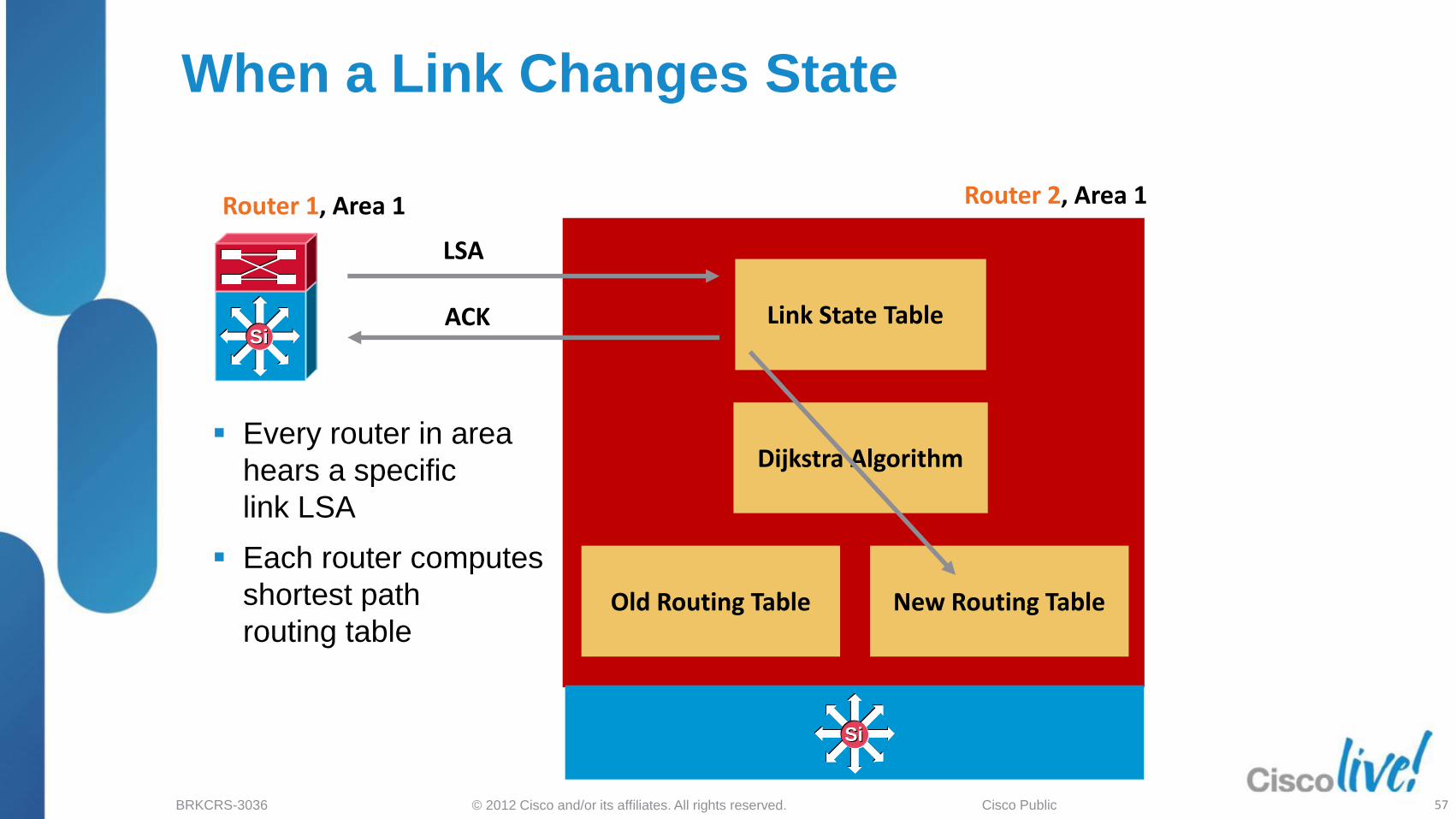
When a Link Changes State
Every router in area
hears a specific
link LSA
Each router computes
shortest path
routing table
Router 2, Area 1
Old Routing Table New Routing Table
Link State Table
LSA
Dijkstra Algorithm
ACK SiSi
Router 1, Area 1
57
Si Si

© 2012 Cisco and/or its affiliates. All rights reserved. BRKCRS-3036 Cisco Public
OSPF LSA Process LSAs Propagate the Event
OSPF is a Link State protocol; it relies on all
routers within an area having the same
topology view of the network.
If a route is lost, OSPF sends out an LSA to
inform it‘s peers of the lost route.
All routers with knowledge of this route in
the OSPF network will receive an LSA and
run SPF to remove the lost route.
The fewer the number of routers with
knowledge of the route, the faster OSPF
converges;
Solution is to limit LSA propagation range SiSiSiSi
LSA 2
SiSiSiSi
SiSiSiSi
LSA 2
LSA 2
LSA 2
LSA 2
LSA 2
LSA 2
LSA 2
LSA 2
Area 0
Area 0
SPF
SPF SPF
SPF
SPF SPF
SPF SPF
SPF SPF
Access
Distribution
Core
Distribution
Access
58

© 2012 Cisco and/or its affiliates. All rights reserved. BRKCRS-3036 Cisco Public
SiSiSiSi
Backbone Area 0
Area 120
OSPF Regular Area ABRs Forward All LSAs from Backbone
ABR Forwards the Following into an Area Summary LSAs (Type 3)
ASBR Summary (Type 4)
Specific Externals (Type 5)
Access Config: router ospf 100
network 10.120.0.0 0.0.255.255 area 120
Distribution Config router ospf 100
area 120 range 10.120.0.0 255.255.0.0 cost 10
network 10.120.0.0 0.0.255.255 area 120
network 10.122.0.0 0.0.255.255 area 0
SiSiSiSi
External Routes/LSA Present in Area 120
59

© 2012 Cisco and/or its affiliates. All rights reserved. BRKCRS-3036 Cisco Public
SiSiSiSi
Backbone Area 0
Area 120
OSPF Stub Area Consolidates Specific External Links—Default 0.0.0.0
Stub Area ABR Forwards Summary LSAs
Summary 0.0.0.0 Default
Distribution Config router ospf 100
area 120 stub
area 120 range 10.120.0.0 255.255.0.0 cost 10
network 10.120.0.0 0.0.255.255 area 120
network 10.122.0.0 0.0.255.255 area 0
SiSiSiSi
Access Config: router ospf 100
network 10.120.0.0 0.0.255.255 area 120
Eliminates External Routes/LSA Present in Area (Type 5)
60

© 2012 Cisco and/or its affiliates. All rights reserved. BRKCRS-3036 Cisco Public
SiSi
Backbone Area 0
Area 120
A Totally Stubby Area ABR Forwards Summary Default
OSPF Totally Stubby Area Use This for Stable—Scalable Internetworks
Distribution Config router ospf 100
area 120 stub no-summary
area 120 range 10.120.0.0 255.255.0.0 cost 10
network 10.120.0.0 0.0.255.255 area 120
network 10.122.0.0 0.0.255.255 area 0
Access Config: router ospf 100
network 10.120.0.0 0.0.255.255 area 120
SiSi
SiSi
SiSi
Minimize the Number of LSAs and the Need for Any External Area SPF Calculations
61

© 2012 Cisco and/or its affiliates. All rights reserved. BRKCRS-3036 Cisco Public
SiSi
Backbone Area 0
Area 120
Area Border Router
ABRs Forward Summary 10.120.0.0/16
Summarization Distribution to Core Reduce SPF and LSA Load in Area 0
Access Config: router ospf 100
network 10.120.0.0 0.0.255.255 area 120
Distribution Config router ospf 100
area 120 stub no-summary
area 120 range 10.120.0.0 255.255.0.0 cost 10
network 10.120.0.0 0.0.255.255 area 120
network 10.122.0.0 0.0.255.255 area 0
SiSi
SiSiSiSi
Minimize the Number of LSAs and the Need for Any SPF Recalculations at the Core
62

© 2012 Cisco and/or its affiliates. All rights reserved. BRKCRS-3036 Cisco Public
SiSiSiSi
SiSiSiSi
OSPF Design Considerations What Area Should the Distribution Link Be In?
Two aspects of OSPF behavior can
impact convergence
‒ OSPF ABRs ignore LSAs generated by other
ABRs learned through non-backbone areas
when calculating least-cost paths
‒ In a stub area environment the ABR will
generate a default route when any type
of connectivity to the backbone exists
Ensure loopbacks are ‘not’ in area 0
Configure dist to dist link as a trunk
using 2 subnets one in area 0 and
one in stub area when possible
63

© 2012 Cisco and/or its affiliates. All rights reserved. BRKCRS-3036 Cisco Public
SiSi
SiSi
OSPF Timer Tuning High-Speed Campus Convergence
OSPF by design has a number of throttling mechanisms to prevent the network from thrashing during periods of instability
Campus environments are candidates to utilize OSPF timer enhancements ‒ Sub-second hellos*
‒ Generic IP (interface) dampening mechanism
‒ Back-off algorithm for LSA generation
‒ Exponential SPF backoff
‒ Configurable packet pacing
Reduce LSA and SPF
Interval
SiSi
SiSi
Reduce Hello Interval
* Not recommended with NSF/SSO
64

© 2012 Cisco and/or its affiliates. All rights reserved. BRKCRS-3036 Cisco Public
Access Config: interface GigabitEthernet1/1 dampening ip ospf dead-interval minimal hello-multiplier 4 ip ospf network point-to-point router ospf 100 timers throttle spf 10 100 5000 timers throttle lsa all 10 100 5000 timers lsa arrival 80
Subsecond Hellos Neighbor Loss Detection—Physical Link Up
OSPF hello/dead timers detect neighbor loss in the absence of physical link loss
Useful where an L2 device separates L3 devices (Layer 2 core designs)
Fast timers quickly detect neighbor failure ‒ Not recommended with NSF/SSO
Interface dampening is recommended with sub-second hello timers
OSPF point-to-point network type to avoid designated router (DR) negotiation.
OSPF Processing
Failure (Link Up)
A B
SiSi
SiSi
SiSi
SiSi
65
© 2012 Cisco and/or its affiliates. All rights reserved. BRKCRS-3036 Cisco Public
5.68
0.72
0.24
0
1
2
3
4
5
6
Default
Convergence
10 msec. SPF 10 msec. SPF
and LSA
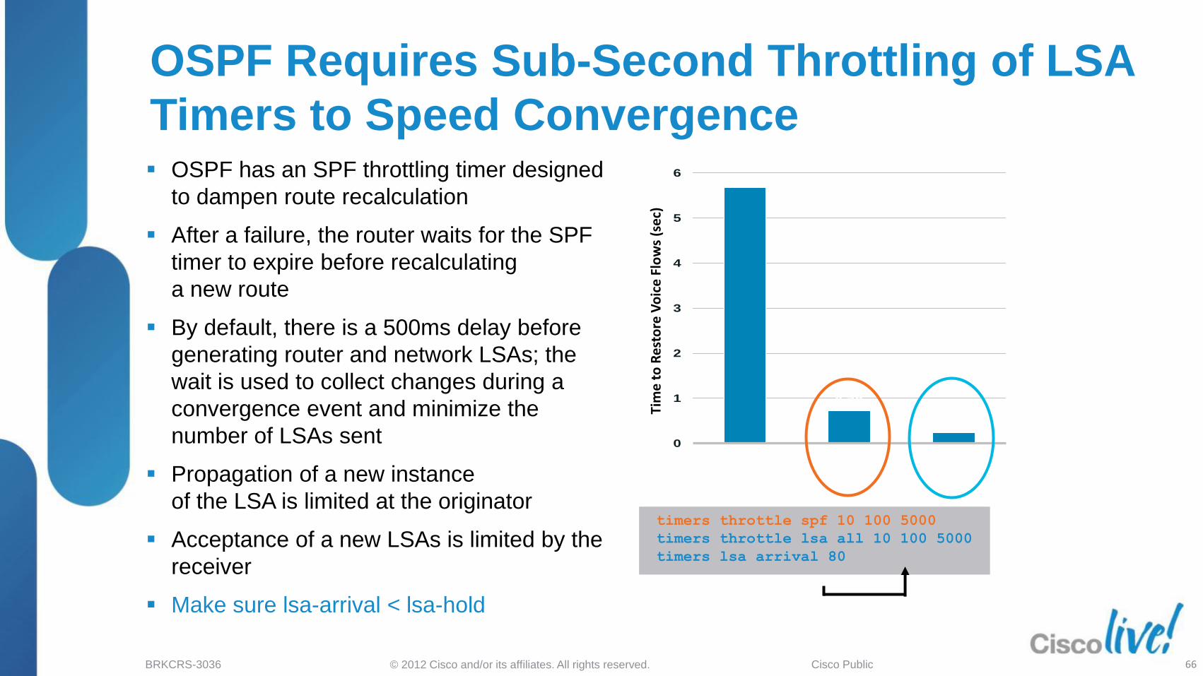
OSPF Requires Sub-Second Throttling of LSA
Timers to Speed Convergence OSPF has an SPF throttling timer designed
to dampen route recalculation
After a failure, the router waits for the SPF
timer to expire before recalculating
a new route
By default, there is a 500ms delay before
generating router and network LSAs; the
wait is used to collect changes during a
convergence event and minimize the
number of LSAs sent
Propagation of a new instance
of the LSA is limited at the originator
Acceptance of a new LSAs is limited by the
receiver
Make sure lsa-arrival < lsa-hold
Tim
e t
o R
est
ore
Vo
ice
Flo
ws
(se
c)
timers throttle spf 10 100 5000
timers throttle lsa all 10 100 5000
timers lsa arrival 80
timers throttle spf 10 100 5000
timers throttle lsa all 10 100 5000
timers lsa arrival 80
66

© 2012 Cisco and/or its affiliates. All rights reserved. BRKCRS-3036 Cisco Public
OSPF Design Rules for HA Campus LSA/SPF Exponential Back-off Throttle Mechanism
timers throttle spf <spf-start> <spf-hold> <spf-max-wait>
timers throttle lsa all <lsa-start> <lsa-hold> <lsa-max-wait>
Time [ms]
Topology Change Events
SPF Calculations
200 1600 msec 100 400 800 msec
timers throttle spf 10 100 5000
timers throttle lsa all 10 100 5000
Sub-second timers without risk
1. spf-start (initial hold timer) controls how long to wait prior to starting the SPF calculation
2. If a new topology change event is received during the spf-hold interval, the SPF calculation
is delayed until the hold interval expires and the hold interval is temporarily doubled
3. The spf-hold interval can grow until the maximum period spf-max-wait is reached
4. After the expiration of any hold interval, the spf-hold timer is reset
67

© 2012 Cisco and/or its affiliates. All rights reserved. BRKCRS-3036 Cisco Public
Enterprise Campus Design: Routed Access
Introduction
Cisco Campus Architecture Review
Campus Routing Foundation and Best Practices
Building a Routed Access Campus Design
‒ EIGRP Design to Route to the Access Layer
‒ OSPF Design to Route to the Access Layer
‒ Other Design Considerations
Routed Access Design and VSS
Routed Access Design for IPv6
Impact of Routed Access Design for Advanced Technologies
Agenda
68

© 2012 Cisco and/or its affiliates. All rights reserved. BRKCRS-3036 Cisco Public
IP Event Dampening to Reduce Routing Churn
Prevents routing protocol churn caused by constant
interface state changes
Dampening is applied on a system: nothing
is exchanged between routing protocols
Supports all IP routing protocols
‒ Static routing, RIP, EIGRP, OSPF, IS-IS, BGP
‒ In addition, it supports HSRP and CLNS routing
‒ Applies on physical interfaces and can‘t be applied on
subinterfaces individually
Up
Up
Interface State Perceived by EIGRP or OSPF
Interface State
interface GigabitEthernet1/1
description Uplink to Distribution 1
dampening
ip address 10.120.0.205 255.255.255.254
Down
Up
Down
SiSi
SiSiSiSi
Up Down
Up
Up Down
Down
69

© 2012 Cisco and/or its affiliates. All rights reserved. BRKCRS-3036 Cisco Public
Adjacency Table
FIB Table
Adjacency Table
FIB Table
Redundant Supervisors with L3 Non-Stop-Forwarding with Stateful Switchover (NSF/SSO)
Active Supervisor
Cisco IOS CEF Tables Synchronization
Hardware Tables Synchronization
Configuration
Hardware
RP CPU
IOS CEF Tables
Routing Protocol process
Routing Information Base ARP Table
Control Path
Standby Supervisor
Forwarding Path
Synchronization
Adjacency Table
FIB Table
Adjacency Table
FIB Table
Hardware
RP CPU
IOS CEF Tables
ARP Table
70

© 2012 Cisco and/or its affiliates. All rights reserved. BRKCRS-3036 Cisco Public
1. Supervisor switchover event occurs
2. SSO maintains SSO-aware applications,
including L2 tables, L2/L3 forwarding is
maintained
3. Routing protocols will restart on the newly
active Supervisor
‒ L3 routes are purged stopping L3 forwarding
4. Routing neighbors lose adjacency with the
restarting router
‒ Routes to the lost neighbor are purged
5. Routing neighbors reestablish
adjacencies, forwarding to and from non-
directly connected L3 networks resumes
Access Layer Redundant Supervisors with SSO
SiSiSiSi
SiSi SiSi
SSO alone is not enough with a Routed Access
do not run SSO w/o NSF in the RA design
71

© 2012 Cisco and/or its affiliates. All rights reserved. BRKCRS-3036 Cisco Public
NSF—Configuration and Monitoring
Switch(config)#router eigrp 100
Switch(config-router)#nsf
Router#sh ip ospf Routing Process "ospf 100" with ID 10.120.250.4 Start time: 00:01:37.484, Time elapsed: 3w2d Supports Link-local Signaling (LLS) <snip> Non-Stop Forwarding enabled, last NSF restart 3w2d ago (took 31 secs)
Router#sh ip protocol
*** IP Routing is NSF aware ***
Routing Protocol is "eigrp 100 100"
<snip
EIGRP NSF-aware route hold timer is 240s
EIGRP NSF enabled
EIGRP
Switch(config)#router ospf 100
Switch(config-router)#nsf
NSF-Capable
NSF-Aware
OSPF
Recommendation Is to Not Tune IGP Hello Timers. Use Default Hello and Dead Timers for EIGRP/OSPF When Peering to a Device Configured for NSF/SSO
72

© 2012 Cisco and/or its affiliates. All rights reserved. BRKCRS-3036 Cisco Public
1. Supervisor switchover event occurs
2. SSO maintains SSO-aware applications, including L2 tables, L2/L3 forwarding is maintained
3. NSF-capable router signals NSF-aware routing peers of a routing protocol restart
4. NSF-aware routers detect the restarting router
‒ Assist in re-establishing full adjacency
‒ Maintain forwarding to and from the restarting router
5. NSF restart complete, traditional L3 convergence event is avoided
Access Layer Redundant Supervisors,
Now with NSF/SSO
2
SiSiSiSi
SiSi SiSi
1
4
3
73

© 2012 Cisco and/or its affiliates. All rights reserved. BRKCRS-3036 Cisco Public
Design with Redundant for NSF/SSO Status of Uplinks of the Supervisor
Cisco Catalyst 4500: supervisor uplink
ports are active and forward traffic as long
as the supervisor is fully inserted
‒ Uplink ports do not go down when a supervisor
is reset. There are restrictions on which ports
can be active simultaneously in redundant
systems
Cisco Catalyst 6500: both the active
supervisor and the standby supervisor
uplink ports are active as long as the
supervisors are up and running
Uplink ports go down when the supervisor is reset
• Catalyst 6500 Supervisors: all ports are active
1/1 1/3 1/4 1/5 1/6 1/2
2/1 2/3 2/4 2/5 2/6 2/2
1/1 1/2
2/1 2/2
• Catalyst 4500 Supervisor II+, Supervisor IV: 2 x GigE ports are active
• Catalyst 4500 Supervisor II+10GE: 2 x 10GE and 4 x GigE ports are active
An NSF/SSO switchover also modifies topology
74

© 2012 Cisco and/or its affiliates. All rights reserved. BRKCRS-3036 Cisco Public
SiSiSiSi
SiSiMaster
Access
S1 S2 S3
Single logical Switch
SiSiSiSi
StackWise at the Access Layer
Recommended Design:
‒ Configure priority for master and its backup for deterministic failures
‒ Avoid using master as uplink to reduce uplink related losses
‒ Use ―stack-mac persistent timer 0‖ to avoid the gratuitous ARP changes for
Best convergence
Where GARP processing is disabled in the network, e.g. Security
Where network devices/host do not support GARP, e.g. Phones
Upstream traffic is not interrupted by master failure
Downstream traffic is interrupted due to routing protocol restart and adjacency reset
‒ Run 12.2(37)SE or higher for NSF support
75
© 2012 Cisco and/or its affiliates. All rights reserved. BRKCRS-3036 Cisco Public
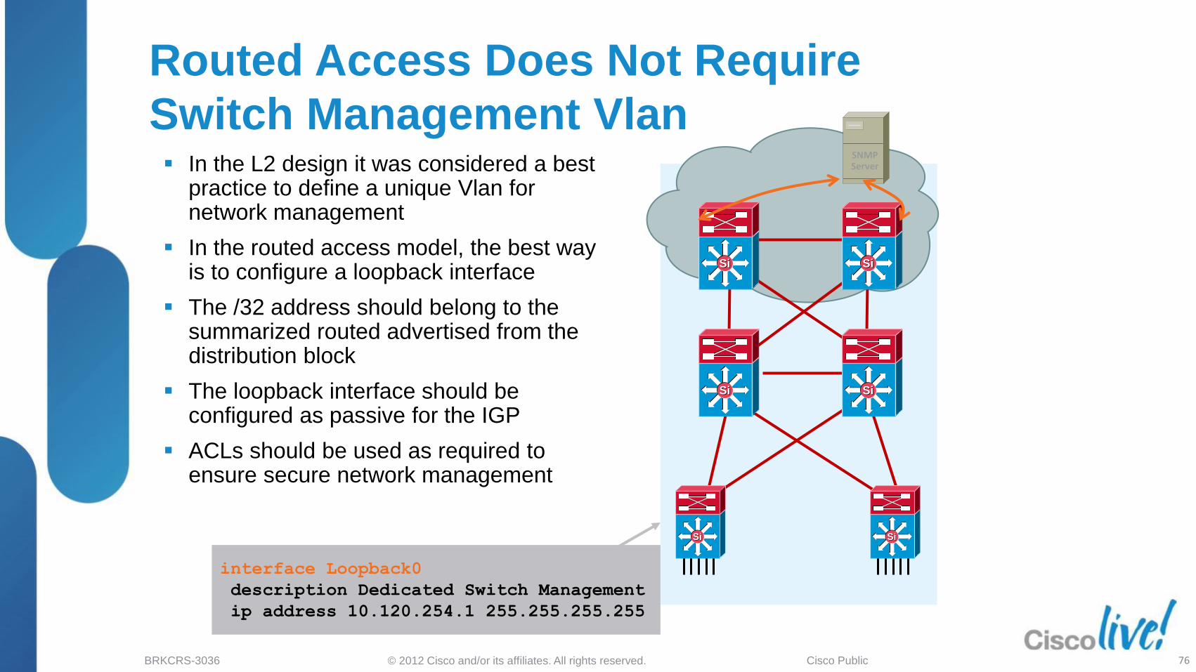
Routed Access Does Not Require
Switch Management Vlan In the L2 design it was considered a best
practice to define a unique Vlan for network management
In the routed access model, the best way is to configure a loopback interface
The /32 address should belong to the summarized routed advertised from the distribution block
The loopback interface should be configured as passive for the IGP
ACLs should be used as required to ensure secure network management
SiSi
SiSiSiSi
SiSi
SiSi SiSi
SNMP Server
interface Loopback0
description Dedicated Switch Management
ip address 10.120.254.1 255.255.255.255
76

© 2012 Cisco and/or its affiliates. All rights reserved. BRKCRS-3036 Cisco Public
Enterprise Campus Design: Routed Access
Introduction
Cisco Campus Architecture Review
Campus Routing Foundation and Best Practices
Building a Routed Access Campus Design
Routed Access Design and VSS
Routed Access Design for IPv6
Impact of Routed Access Design for Advanced Technologies
Summary
Agenda
77

© 2012 Cisco and/or its affiliates. All rights reserved. BRKCRS-3036 Cisco Public
Virtual Switch
Virtual Switching System consists of two Catalyst 6500‘s
defined as members of the same virtual switch domain running
a VSL (Virtual Switch Link) between them
Single Control Plane with Dual Active Forwarding Planes
Extends NSF/SSO infrastructure to Two Switches
Catalyst 6500 Virtual Switching System (VSS)
VSS
SiSiSiSi
Switch 1 + Switch 2 =
Virtual Switch Domain
Virtual Switch Link (VSL)
78

© 2012 Cisco and/or its affiliates. All rights reserved. BRKCRS-3036 Cisco Public
Virtual Switch System
Multi-chassis Etherchannel (MEC) replaces
spanning tree to provide link redundancy
MEC allows the physical members of the
Etherchannel bundle to be connected to two
separate physical switches
MEC links on both switches are managed by PAgP
or LACP running on the Master Switch via internal
control messages
PAgP or LACP packets for all links in the MEC
bundle are processed by the active supervisor
Multi-Chassis Etherchannel
Multi-Chassis Etherchannel
79
© 2012 Cisco and/or its affiliates. All rights reserved. BRKCRS-3036 Cisco Public
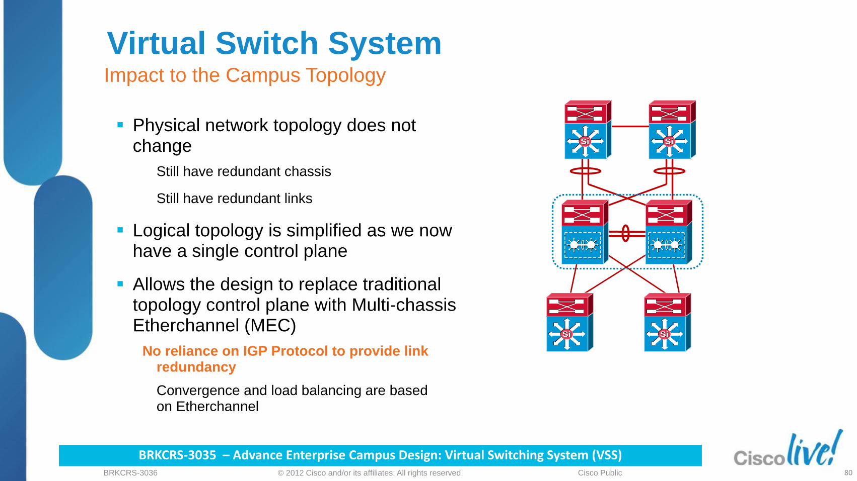
Virtual Switch System Impact to the Campus Topology
Physical network topology does not
change
‒ Still have redundant chassis
‒ Still have redundant links
Logical topology is simplified as we now
have a single control plane
Allows the design to replace traditional
topology control plane with Multi-chassis
Etherchannel (MEC)
‒ No reliance on spanning tree to provide link
redundancy
‒ Convergence and load balancing are based
on Etherchannel
Physical network topology does not change
Still have redundant chassis
Still have redundant links
Logical topology is simplified as we now have a single control plane
Allows the design to replace traditional topology control plane with Multi-chassis Etherchannel (MEC)
No reliance on IGP Protocol to provide link redundancy
Convergence and load balancing are based on Etherchannel
BRKCRS-3035 – Advance Enterprise Campus Design: Virtual Switching System (VSS) 80
SiSiSiSi SiSiSiSi SiSiSiSi SiSiSiSi
SiSiSiSi

© 2012 Cisco and/or its affiliates. All rights reserved. BRKCRS-3036 Cisco Public
Leveraging EtherChannel Time to Recovery
Catalyst Switch
Link failure detection
Removal of the Portchannel entry in the software
Update of the hardware Portchannel indices
1 Link Failure Detection
SiSi SiSi
2
1
2
3
3
Routing Protocol Process
Spanning Tree Process
Notify the spanning tree and/or routing protocol processes of path cost change
4
4
Layer 2 Forwarding Table
Load-Balancing Hash
Destination Port
G3/1
G3/2
G4/1
G4/2
VLAN MAC Destination
Index
10 AA Portchannel 1
11 BB G5/1
PortChannel 1 G3/1, G3/2, G4/1, G4/2
81

© 2012 Cisco and/or its affiliates. All rights reserved. BRKCRS-3036 Cisco Public
VSS and Routed Access Design Link Down Convergence Without VSS
Downstream IGP reroute Upstream CEF ECMP
SiSi
SiSi
SiSi
SiSi
L3 ECMP
Downstream traffic recovery is dependent upon the Interior Gateway Protocol reroute to the peer distribution switch
‒ Use Stub on the access devices, and proper summarization from distribution
‒ Tune IGP ... etc.
Upstream traffic recovery is dependent upon updates to the Access Switch‘s Forwarding Information Base removing the adjacency for the lost link (ECMP)
82

© 2012 Cisco and/or its affiliates. All rights reserved. BRKCRS-3036 Cisco Public
VSS and Routed Access Design Link Down Convergence with VSS MEC
Access layer switch has one neighbor
Distribution switch has neighbor count
reduced by half
Upstream and Downstream traffic
convergence now is an Etherchannel
link event
‒ No IGP reconvergence event
‒ No Impact of number of routes/vlans
Fast IGP Timers not needed nor
recommended (only 1 IGP peer)
Summarization rules still recommended
Achieves sub-second failure and no L2
loop on the topology
83
Downstream IGP reroute Upstream CEF ECMP
SiSi
SiSiSiSi
SiSi
L3 ECMP MEC

© 2012 Cisco and/or its affiliates. All rights reserved. BRKCRS-3036 Cisco Public
VSS and Routed Access Design Enable MEC Links in L3 Core—Best Multicast
Use MEC uplinks from the access in routed access environments with multicast traffic
VSS MEC local switch link preference avoids egress replication across the VSL link during normal conditions
In the event of link failure multicast traffic will pass across VSL link and will experience local switch replication
Large scale mroute and s,g topology the convergence may vary, however much better then ECMP based topology
L3 MEC Uplinks
SiSiSiSi
MEC Uplinks
PIM Joins
PIM Join
SW1 ACTIVE
SW2 HOT_STANBY
84

© 2012 Cisco and/or its affiliates. All rights reserved. BRKCRS-3036 Cisco Public
Enterprise Campus Design: Routed Access
Introduction
Cisco Campus Architecture Review
Campus Routing Foundation and Best Practices
Building a Routed Access Campus Design
Routed Access Design and VSS
Routed Access Design for IPv6
Impact of Routed Access Design for Advanced Technologies
Summary
Agenda
85

© 2012 Cisco and/or its affiliates. All rights reserved. BRKCRS-3036 Cisco Public
Routed Access Layer and IPv6
IPv4 and IPv6 Dual Stack is the
recommended deployment model
In RA model, the first hop switch must be
capable of routing IPv6
EIGRP-Stub and OSPFv3 Routed Access
Catalyst IPv6 Routing
Cisco Catalyst 6500 Series Switches
SUP32, SUP720, SUP2T
Cisco Catalyst 4500 Series Switches
SUP6-E and higher
Cisco Catalyst 3750 Series, E Series,
and X Series Switches
Cisco Catalyst 3560 Series, E Series,
and X Series Switches
Support for Dual Stack Deployment
86

© 2012 Cisco and/or its affiliates. All rights reserved. BRKCRS-3036 Cisco Public
Dual-stack Server
L3
v6-Enabled
v6- Enabled
v6-Enabled
v6- Enabled
IPv6/IPv4 Dual Stack Hosts
v6- Enabled
v6- Enabled
Aggregation Layer (DC)
Access Layer (DC)
Access Layer
Distribution Layer
Core Layer
Du
al S
tack
Du
al S
tack
ipv6 unicast-routing
ipv6 cef
!
[...]
interface Vlan2
description Data VLAN for Access
ipv6 address 2001:DB8:CAFE:2::CAC1:3750/64
ipv6 nd prefix 2001:DB8:CAFE:2::/64 no-advertise
ipv6 nd managed-config-flag
ipv6 nd other-config-flag
ipv6 dhcp relay destination 2001:DB8:CAFE:10::2
ipv6 ospf 1 area 2
ipv6 cef
!
[...]
ipv6 router ospf 1
router-id 10.120.2.1
log-adjacency-changes
auto-cost reference-bandwidth 10000
area 2 stub no-summary
passive-interface Vlan2
timers spf 1 5
Routed Access Layer and IPv6 Dual Stack Deployment Sample
For Your Reference
87

© 2012 Cisco and/or its affiliates. All rights reserved. BRKCRS-3036 Cisco Public
Dual-stack Server
L3
v6-Enabled
v6- Enabled
v6-Enabled
v6- Enabled
IPv6/IPv4 Dual Stack Hosts
v6- Enabled
v6- Enabled
Aggregation Layer (DC)
Access Layer (DC)
Access Layer
Distribution Layer
Core Layer
!
interface GigabitEthernet1/0/25
description To 6k-dist-1
ipv6 address 2001:DB8:CAFE:1100::CAC1:3750/64
no ipv6 redirects
ipv6 nd suppress-ra
ipv6 ospf network point-to-point
ipv6 ospf 1 area 2
ipv6 ospf hello-interval 1
ipv6 ospf dead-interval 3
ipv6 cef
!
interface GigabitEthernet1/0/26
description To 6k-dist-2
ipv6 address 2001:DB8:CAFE:1101::CAC1:3750/64
no ipv6 redirects
ipv6 nd suppress-ra
ipv6 ospf network point-to-point
ipv6 ospf 1 area 2
ipv6 ospf hello-interval 1
ipv6 ospf dead-interval 3
ipv6 cef
Routed Access Layer and IPv6 Dual Stack Deployment Sample
For Your Reference
Du
al S
tack
Du
al S
tack
88

© 2012 Cisco and/or its affiliates. All rights reserved. BRKCRS-3036 Cisco Public
Enterprise Campus Design: Routed Access
Introduction
Cisco Campus Architecture Review
Campus Routing Foundation and Best Practices
Building a Routed Access Campus Design
Routed Access Design and VSS
Routed Access Design for IPv6
Impact of Routed Access Design for Advanced Technologies
Summary
Agenda
89

© 2012 Cisco and/or its affiliates. All rights reserved. BRKCRS-3036 Cisco Public
Analyzing the Impact on Advanced
Technologies Unified Communications Deployments work the same way. You still need to
provision a voice vlan/subnet per wiring closet switch
TrustSec (802.1x) solutions work the same: user vlan assignment still possible, as
well as per user dACL (checkout BRKSEC-2005)
Wireless LAN works seamlessly as well, since LWAPP works with UDP hence at L3.
We will take a closer look at;
‒ Network Virtualization
90

© 2012 Cisco and/or its affiliates. All rights reserved. BRKCRS-3036 Cisco Public
Network Virtualization Functional Architecture
Access control techniques remain the same with a Routed Access Model
Path Isolation techniques remain the same, but there are provisioning implications by running routing at the access layer
Access Control Path Isolation Services Edge
WAN – MAN – Campus Branch – Campus Data Center – Internet Edge – Campus
Ethernet VRFs
GRE VRFs
MPLS VPNs
BRKCRS-2033 – Deploying a Virtualized Campus Network Infrastructure
91

© 2012 Cisco and/or its affiliates. All rights reserved. BRKCRS-3036 Cisco Public
Path Isolation Functional Components
VRF
VRF
Global
Device virtualization
‒Control plane virtualization
‒Data plane virtualization
‒Services virtualization
Data path virtualization
Hop-by-Hop:
VRF-Lite End-to-End
Multi-Hop:
VRF-Lite+GRE, MPLS-VPN
VRF: Virtual Routing and Forwarding
Per VRF Virtual Routing Table
Virtual Forwarding Table
IP
802.1q
92

© 2012 Cisco and/or its affiliates. All rights reserved. BRKCRS-3036 Cisco Public
Network Virtualization and Routed Access Path Isolation Issues—VRFs to the Edge
Define VRFs on the access layer switches
One VRF dedicated to each virtual network (Red, Green, etc.)
Map device VLANs to corresponding VRF
Provisioning is more challenging, because multiple routing processes and logical interfaces are required.
The chosen path isolation technique must be deployed from the access layer devices
EVNs
VRF-lite Ethernet
VRF-Lite GRE
MPLS L3 VPNs
Campus Core
Layer 3 Links
SiSiSiSi
VLAN 21 Red
VLAN 22 Green
VLAN 23 Blue
VLAN 21 Red
VLAN 22 Green
VLAN 23 Blue VRF Blue
VRF Green
VRF Red
93

© 2012 Cisco and/or its affiliates. All rights reserved. BRKCRS-3036 Cisco Public
Virtualizing at the Access Layer VLANs to VRF Mapping Configuration
ip vrf Red
!
ip vrf Green
!
vlan 21
name Red_access_switch_1
!
vlan 22
name Green_access_switch_1
!
interface Vlan21
description Red on Access Switch 1
ip vrf forwarding Red
ip address 12.137.21.1 255.255.255.0
!
interface Vlan22
description Green on Access Switch 1
ip vrf forwarding Green
ip address 11.137.22.1 255.255.255.0
Defining the VRFs
Defining the VLANs (L2 and SVI) and Mapping Them to the VRFs
94

© 2012 Cisco and/or its affiliates. All rights reserved. BRKCRS-3036 Cisco Public
VRF-Lite – Routing Protocol Example
OS
PF
Exa
mple
router ospf 1
network 10.0.0.0 0.255.255.255 area 0
passive-interface default
no passive-interface vlan 2000
!
router ospf 100 vrf green
network 11.0.0.0 0.255.255.255 area 0
no passive-interface vlan 2001
!
router ospf 200 vrf red
network 12.0.0.0 0.255.255.255 area 0
no passive-interface vlan 2002
router eigrp 100
network 10.0.0.0 0.255.255.255
passive-interface default
no passive-interface vlan 2000
no auto-summary
!
address-family ipv4 vrf green autonomous-system 100
network 11.0.0.0 0.255.255.255
no auto-summary
exit-address-family
!
address-family ipv4 vrf red autonomous-system 100
network 12.0.0.0 0.255.255.255
no auto-summary
exit-address-family
EIG
RP
Exa
mple
95
Defining the Routing Protocol within the VRFs
95

© 2012 Cisco and/or its affiliates. All rights reserved. BRKCRS-3036 Cisco Public
Network Virtualization and Routed Access Path Isolation Issues—VRFs to the Edge (Cont.)
Catalyst 6500 supports all three
path isolation techniques:
‒ 802.1Q Ethernet VRF-Lite
‒ GRE with VRF-Lite
‒ MPLS VPN
Catalyst 3000s and 4500s only
support 802.1Q Ethernet VRF-Lite
Convergence times increase
‒ ~800ms for 9 VRFs + Global
‒ Increased load from multiple routing
processes and logical interfaces
Operational impact of managing
multiple logical networks
Campus Core
Layer 3 Links
SiSiSiSi
VLAN 21 Red
VLAN 22 Green
VLAN 23 Blue
VLAN 21 Red
VLAN 22 Green
VLAN 23 Blue VRF Blue
VRF Green
VRF Red
Network Virtualization--Path Isolation Design Guide http://www.cisco.com/en/US/docs/solutions/Enterprise/Network_Virtualization/PathIsol.html#wp277205 96

© 2012 Cisco and/or its affiliates. All rights reserved. BRKCRS-3036 Cisco Public
Easy Virtual Networks (EVN) Summary
A simple, IP-based L3 VPN network virtualization solution
‒ Makes VRF-lite easier to deploy, operate and scale
‒ Based on existing network designs
‒ Interoperable with VRF-lite and MPLS-VPN
LAN VNET Trunks
VLAN-ID reuse
Sub-interface inheritance
Route Replication
IGP based Shared Services
Enhanced Troubleshooting and Usability
routing-context, traceroute, debug condition, cisco-vrf-mib
New
97
BRKVIR-2009 - Present and Future Services in Network Virtualization

© 2012 Cisco and/or its affiliates. All rights reserved. BRKCRS-3036 Cisco Public
EVN - Easy Virtual Network Roadmap
Platform Phase 1
ASR1K IOS XE 3.2S
Cat6K – Sup2T 15.0(1)SY1
Cat4K IOS XE 3.3.0 SG, 15.1(1)SG
Cat6K – Sup720* Future
Cat3K-X Future
ISR-G2 Future
Nexus 7K Future
EVN is planned to be available on all platforms and versions in 12-18 months
“Many of the products and features described herein remain in varying stages of development and will be offered on a when-and-if-available basis. This roadmap is subject to change at the sole discretion of Cisco, and Cisco will have no liability for delay in the delivery or failure to deliver any of the products or features set forth in this document.”
98

© 2012 Cisco and/or its affiliates. All rights reserved. BRKCRS-3036 Cisco Public
Enterprise Campus Design: Routed Access
Introduction
Cisco Campus Architecture Review
Campus Routing Foundation and Best Practices
Building a Routed Access Campus Design
Routed Access Design and VSS
Routed Access Design for IPv6
Impact of Routed Access Design for Advanced Technologies
Summary
Agenda
99

© 2012 Cisco and/or its affiliates. All rights reserved. BRKCRS-3036 Cisco Public
= STP Blocked Link
STP-Based Redundant Topology
B
SiSi SiSi
SiSi SiSi
SiSi SiSi
Routed Access Redundant Topology
SiSi SiSi
SiSi SiSi
SiSi SiSi
SiSi SiSi
SiSi SiSi
Routed Access Campus Design End to End Routing: Fast Convergence and Maximum Reliability
B
B B
B
100

© 2012 Cisco and/or its affiliates. All rights reserved. BRKCRS-3036 Cisco Public
Summary
Layer 2 designs remain valid
Routed Access Design:
‒ Simplified Control Plane:
no dependence on STP, HSRP, etc.
‒ Increased Capacity:
flow-based load balancing
‒ High Availability:
200 msec or better recovery
‒ Simplified Multicast
‒ No L2 Loops
fails closed, no flooding
‒ Easy Troubleshooting
Flexibility to provide the right
implementation for each requirement
SiSi SiSi SiSi SiSi
SiSi SiSi
101

© 2012 Cisco and/or its affiliates. All rights reserved. BRKCRS-3036 Cisco Public