enterprise layer 3 multicast implementation guide
TRANSCRIPT

IMPLEMENTATION GUIDE
Copyright © 2009, Juniper Networks, Inc. 1
ENTERPRISE LAYER 3 MULTICAST IMPLEMENTATION GUIDEUsing the EX Series Ethernet Switches and MX Series 3D Universal Edge Routers
Although Juniper Networks has attempted to provide accurate information in this guide, Juniper Networks does not warrant or guarantee the accuracy of the information provided herein. Third party product descriptions and related technical details provided in this document are for information purposes only and such products are not supported by Juniper Networks. All information provided in this guide is provided “as is”, with all faults, and without warranty of any kind, either expressed or implied or statutory. Juniper Networks and its suppliers hereby disclaim all warranties related to this guide and the information contained herein, whether expressed or implied of statutory including, without limitation, those of merchantability, fitness for a particular purpose and noninfringement, or arising from a course of dealing, usage, or trade practice.

2 Copyright © 2009, Juniper Networks, Inc.
IMPLEMENTATION GUIDE - Enterprise Layer 3 Multicast
Table of Contents
Introduction . . . . . . . . . . . . . . . . . . . . . . . . . . . . . . . . . . . . . . . . . . . . . . . . . . . . . . . . . . . . . . . . . . . . . . . . . . . . . . . . . . . . . . . . . . . . . . . . . . . . . 4
Scope . . . . . . . . . . . . . . . . . . . . . . . . . . . . . . . . . . . . . . . . . . . . . . . . . . . . . . . . . . . . . . . . . . . . . . . . . . . . . . . . . . . . . . . . . . . . . . . . . . . . . . . . . . 4
Target Audience . . . . . . . . . . . . . . . . . . . . . . . . . . . . . . . . . . . . . . . . . . . . . . . . . . . . . . . . . . . . . . . . . . . . . . . . . . . . . . . . . . . . . . . . . . . . . . . 4
Design Considerations . . . . . . . . . . . . . . . . . . . . . . . . . . . . . . . . . . . . . . . . . . . . . . . . . . . . . . . . . . . . . . . . . . . . . . . . . . . . . . . . . . . . . . . . . . . 4
Choosing the PIM Mode . . . . . . . . . . . . . . . . . . . . . . . . . . . . . . . . . . . . . . . . . . . . . . . . . . . . . . . . . . . . . . . . . . . . . . . . . . . . . . . . . . . . . . . 4
Selecting and Assigning RPs . . . . . . . . . . . . . . . . . . . . . . . . . . . . . . . . . . . . . . . . . . . . . . . . . . . . . . . . . . . . . . . . . . . . . . . . . . . . . . . . . . . 5
Selecting the IGMP Version . . . . . . . . . . . . . . . . . . . . . . . . . . . . . . . . . . . . . . . . . . . . . . . . . . . . . . . . . . . . . . . . . . . . . . . . . . . . . . . . . . . . 6
Reducing Multicast Flooding with IGMP Snooping . . . . . . . . . . . . . . . . . . . . . . . . . . . . . . . . . . . . . . . . . . . . . . . . . . . . . . . . . . . . . . . 6
Reducing IGMP Membership Packets with IGMP Proxy . . . . . . . . . . . . . . . . . . . . . . . . . . . . . . . . . . . . . . . . . . . . . . . . . . . . . . . . . . . 6
Hardware Considerations . . . . . . . . . . . . . . . . . . . . . . . . . . . . . . . . . . . . . . . . . . . . . . . . . . . . . . . . . . . . . . . . . . . . . . . . . . . . . . . . . . . . . . 6
Scaling Numbers on EX3200 and EX4200 Platforms . . . . . . . . . . . . . . . . . . . . . . . . . . . . . . . . . . . . . . . . . . . . . . . . . . . . . . . . . . . . .7
EX Series Multicast Feature Support Summary . . . . . . . . . . . . . . . . . . . . . . . . . . . . . . . . . . . . . . . . . . . . . . . . . . . . . . . . . . . . . . . . . . .7
Implementation . . . . . . . . . . . . . . . . . . . . . . . . . . . . . . . . . . . . . . . . . . . . . . . . . . . . . . . . . . . . . . . . . . . . . . . . . . . . . . . . . . . . . . . . . . . . . . . . . .7
Implementation Guidelines . . . . . . . . . . . . . . . . . . . . . . . . . . . . . . . . . . . . . . . . . . . . . . . . . . . . . . . . . . . . . . . . . . . . . . . . . . . . . . . . . . . . .7
IGMP Configuration . . . . . . . . . . . . . . . . . . . . . . . . . . . . . . . . . . . . . . . . . . . . . . . . . . . . . . . . . . . . . . . . . . . . . . . . . . . . . . . . . . . . . . . . . . . .7
Enabling/Disabling IGMP . . . . . . . . . . . . . . . . . . . . . . . . . . . . . . . . . . . . . . . . . . . . . . . . . . . . . . . . . . . . . . . . . . . . . . . . . . . . . . . . . . . . .7
IGMP Version . . . . . . . . . . . . . . . . . . . . . . . . . . . . . . . . . . . . . . . . . . . . . . . . . . . . . . . . . . . . . . . . . . . . . . . . . . . . . . . . . . . . . . . . . . . . . . . 8
IGMP Timers . . . . . . . . . . . . . . . . . . . . . . . . . . . . . . . . . . . . . . . . . . . . . . . . . . . . . . . . . . . . . . . . . . . . . . . . . . . . . . . . . . . . . . . . . . . . . . . 8
IGMP Immediate-Leave . . . . . . . . . . . . . . . . . . . . . . . . . . . . . . . . . . . . . . . . . . . . . . . . . . . . . . . . . . . . . . . . . . . . . . . . . . . . . . . . . . . . . 9
IGMP Promiscuous Mode . . . . . . . . . . . . . . . . . . . . . . . . . . . . . . . . . . . . . . . . . . . . . . . . . . . . . . . . . . . . . . . . . . . . . . . . . . . . . . . . . . . 9
Static IGMP . . . . . . . . . . . . . . . . . . . . . . . . . . . . . . . . . . . . . . . . . . . . . . . . . . . . . . . . . . . . . . . . . . . . . . . . . . . . . . . . . . . . . . . . . . . . . . . . . 9
IGMP Snooping . . . . . . . . . . . . . . . . . . . . . . . . . . . . . . . . . . . . . . . . . . . . . . . . . . . . . . . . . . . . . . . . . . . . . . . . . . . . . . . . . . . . . . . . . . . . .10
PIM Configuration . . . . . . . . . . . . . . . . . . . . . . . . . . . . . . . . . . . . . . . . . . . . . . . . . . . . . . . . . . . . . . . . . . . . . . . . . . . . . . . . . . . . . . . . . . . . . 11
Static RP . . . . . . . . . . . . . . . . . . . . . . . . . . . . . . . . . . . . . . . . . . . . . . . . . . . . . . . . . . . . . . . . . . . . . . . . . . . . . . . . . . . . . . . . . . . . . . . . . . 11
Auto-RP . . . . . . . . . . . . . . . . . . . . . . . . . . . . . . . . . . . . . . . . . . . . . . . . . . . . . . . . . . . . . . . . . . . . . . . . . . . . . . . . . . . . . . . . . . . . . . . . . . . 11
Bootstrap RP . . . . . . . . . . . . . . . . . . . . . . . . . . . . . . . . . . . . . . . . . . . . . . . . . . . . . . . . . . . . . . . . . . . . . . . . . . . . . . . . . . . . . . . . . . . . . . . 12
Anycast RP with PIM Only . . . . . . . . . . . . . . . . . . . . . . . . . . . . . . . . . . . . . . . . . . . . . . . . . . . . . . . . . . . . . . . . . . . . . . . . . . . . . . . . . . . 12
Implementation Example . . . . . . . . . . . . . . . . . . . . . . . . . . . . . . . . . . . . . . . . . . . . . . . . . . . . . . . . . . . . . . . . . . . . . . . . . . . . . . . . . . . . . . 14
Topology . . . . . . . . . . . . . . . . . . . . . . . . . . . . . . . . . . . . . . . . . . . . . . . . . . . . . . . . . . . . . . . . . . . . . . . . . . . . . . . . . . . . . . . . . . . . . . . . . . . 14
Hardware Used For the Implementation . . . . . . . . . . . . . . . . . . . . . . . . . . . . . . . . . . . . . . . . . . . . . . . . . . . . . . . . . . . . . . . . . . . . . . 15
Software Used For the Implementation . . . . . . . . . . . . . . . . . . . . . . . . . . . . . . . . . . . . . . . . . . . . . . . . . . . . . . . . . . . . . . . . . . . . . . 15
Detailed Configurations . . . . . . . . . . . . . . . . . . . . . . . . . . . . . . . . . . . . . . . . . . . . . . . . . . . . . . . . . . . . . . . . . . . . . . . . . . . . . . . . . . . . . 15
Verification . . . . . . . . . . . . . . . . . . . . . . . . . . . . . . . . . . . . . . . . . . . . . . . . . . . . . . . . . . . . . . . . . . . . . . . . . . . . . . . . . . . . . . . . . . . . . . . . . . 38
General Multicast . . . . . . . . . . . . . . . . . . . . . . . . . . . . . . . . . . . . . . . . . . . . . . . . . . . . . . . . . . . . . . . . . . . . . . . . . . . . . . . . . . . . . . . . . . . . 38
Show Multicast RPF . . . . . . . . . . . . . . . . . . . . . . . . . . . . . . . . . . . . . . . . . . . . . . . . . . . . . . . . . . . . . . . . . . . . . . . . . . . . . . . . . . . . . . . . 38
Show Multicast Route Extensive . . . . . . . . . . . . . . . . . . . . . . . . . . . . . . . . . . . . . . . . . . . . . . . . . . . . . . . . . . . . . . . . . . . . . . . . . . . . 38
Show Multicast Usage. . . . . . . . . . . . . . . . . . . . . . . . . . . . . . . . . . . . . . . . . . . . . . . . . . . . . . . . . . . . . . . . . . . . . . . . . . . . . . . . . . . . . . 39
Show Multicast Next-Hops . . . . . . . . . . . . . . . . . . . . . . . . . . . . . . . . . . . . . . . . . . . . . . . . . . . . . . . . . . . . . . . . . . . . . . . . . . . . . . . . . 39

Copyright © 2009, Juniper Networks, Inc. 3
IMPLEMENTATION GUIDE - Enterprise Layer 3 Multicast
Table of Figures
Figure 1: Network topology . . . . . . . . . . . . . . . . . . . . . . . . . . . . . . . . . . . . . . . . . . . . . . . . . . . . . . . . . . . . . . . . . . . . . . . . . . . . . . . . . . . . . . . 14
PIM . . . . . . . . . . . . . . . . . . . . . . . . . . . . . . . . . . . . . . . . . . . . . . . . . . . . . . . . . . . . . . . . . . . . . . . . . . . . . . . . . . . . . . . . . . . . . . . . . . . . . . . . . . 39
Show PIM RPS Extensive . . . . . . . . . . . . . . . . . . . . . . . . . . . . . . . . . . . . . . . . . . . . . . . . . . . . . . . . . . . . . . . . . . . . . . . . . . . . . . . . . . . 39
Show PIM Interface . . . . . . . . . . . . . . . . . . . . . . . . . . . . . . . . . . . . . . . . . . . . . . . . . . . . . . . . . . . . . . . . . . . . . . . . . . . . . . . . . . . . . . . . 40
Show PIM Neighbor . . . . . . . . . . . . . . . . . . . . . . . . . . . . . . . . . . . . . . . . . . . . . . . . . . . . . . . . . . . . . . . . . . . . . . . . . . . . . . . . . . . . . . . . .41
Show PIM Join . . . . . . . . . . . . . . . . . . . . . . . . . . . . . . . . . . . . . . . . . . . . . . . . . . . . . . . . . . . . . . . . . . . . . . . . . . . . . . . . . . . . . . . . . . . . . .41
Show PIM Source Detail . . . . . . . . . . . . . . . . . . . . . . . . . . . . . . . . . . . . . . . . . . . . . . . . . . . . . . . . . . . . . . . . . . . . . . . . . . . . . . . . . . . . .41
Show PIM Statistics . . . . . . . . . . . . . . . . . . . . . . . . . . . . . . . . . . . . . . . . . . . . . . . . . . . . . . . . . . . . . . . . . . . . . . . . . . . . . . . . . . . . . . . . 42
IGMP . . . . . . . . . . . . . . . . . . . . . . . . . . . . . . . . . . . . . . . . . . . . . . . . . . . . . . . . . . . . . . . . . . . . . . . . . . . . . . . . . . . . . . . . . . . . . . . . . . . . . . . . 43
Show IGMP Interface . . . . . . . . . . . . . . . . . . . . . . . . . . . . . . . . . . . . . . . . . . . . . . . . . . . . . . . . . . . . . . . . . . . . . . . . . . . . . . . . . . . . . . . 43
Show IGMP Group . . . . . . . . . . . . . . . . . . . . . . . . . . . . . . . . . . . . . . . . . . . . . . . . . . . . . . . . . . . . . . . . . . . . . . . . . . . . . . . . . . . . . . . . . 44
Show IGMP Statistics . . . . . . . . . . . . . . . . . . . . . . . . . . . . . . . . . . . . . . . . . . . . . . . . . . . . . . . . . . . . . . . . . . . . . . . . . . . . . . . . . . . . . . 44
Show IGMP Snooping Membership . . . . . . . . . . . . . . . . . . . . . . . . . . . . . . . . . . . . . . . . . . . . . . . . . . . . . . . . . . . . . . . . . . . . . . . . . . 45
Show IGMP Snooping Route Ethernet Switching . . . . . . . . . . . . . . . . . . . . . . . . . . . . . . . . . . . . . . . . . . . . . . . . . . . . . . . . . . . . . 45
Show IGMP Snooping Statistics . . . . . . . . . . . . . . . . . . . . . . . . . . . . . . . . . . . . . . . . . . . . . . . . . . . . . . . . . . . . . . . . . . . . . . . . . . . . 45
Show IGMP Snooping VLANS . . . . . . . . . . . . . . . . . . . . . . . . . . . . . . . . . . . . . . . . . . . . . . . . . . . . . . . . . . . . . . . . . . . . . . . . . . . . . . . 46
Troubleshooting . . . . . . . . . . . . . . . . . . . . . . . . . . . . . . . . . . . . . . . . . . . . . . . . . . . . . . . . . . . . . . . . . . . . . . . . . . . . . . . . . . . . . . . . . . . . . 46
Confirming the Presence of De-Encapsulation (pd) or Encapsulation (pe) Interfaces . . . . . . . . . . . . . . . . . . . . . . . . . . 46
Verifying Multicast Routes in Forwarding Table . . . . . . . . . . . . . . . . . . . . . . . . . . . . . . . . . . . . . . . . . . . . . . . . . . . . . . . . . . . . . . . 46
Clearing Statistics and Usage . . . . . . . . . . . . . . . . . . . . . . . . . . . . . . . . . . . . . . . . . . . . . . . . . . . . . . . . . . . . . . . . . . . . . . . . . . . . . . . 46
Trace Options . . . . . . . . . . . . . . . . . . . . . . . . . . . . . . . . . . . . . . . . . . . . . . . . . . . . . . . . . . . . . . . . . . . . . . . . . . . . . . . . . . . . . . . . . . . . . . 46
Summary . . . . . . . . . . . . . . . . . . . . . . . . . . . . . . . . . . . . . . . . . . . . . . . . . . . . . . . . . . . . . . . . . . . . . . . . . . . . . . . . . . . . . . . . . . . . . . . . . . . . . . 47
Appendixes . . . . . . . . . . . . . . . . . . . . . . . . . . . . . . . . . . . . . . . . . . . . . . . . . . . . . . . . . . . . . . . . . . . . . . . . . . . . . . . . . . . . . . . . . . . . . . . . . . . . 47
Appendix A: Conventions/Glossary . . . . . . . . . . . . . . . . . . . . . . . . . . . . . . . . . . . . . . . . . . . . . . . . . . . . . . . . . . . . . . . . . . . . . . . . . . . 47
About Juniper Networks . . . . . . . . . . . . . . . . . . . . . . . . . . . . . . . . . . . . . . . . . . . . . . . . . . . . . . . . . . . . . . . . . . . . . . . . . . . . . . . . . . . . . . . . . 48

4 Copyright © 2009, Juniper Networks, Inc.
IMPLEMENTATION GUIDE - Enterprise Layer 3 Multicast
Introduction
Enterprise customers are increasingly deploying IP multicast forwarding in their networks to deliver applications such
as video conferencing, distance learning, and distribution of software, stock quotes, and news. They use Protocol
Independent Multicast (PIM) for multicast signaling and the Internet Group Management Protocol (IGMP) to manage
host multicast group membership.
The objective of this document is to provide a Layer 3 multicast implementation guide for enterprise networks using
the Juniper Networks® EX Series Ethernet Switches and Juniper Networks MX Series 3D Universal Edge Routers.
This document targets deployments where the EX Series is used in the access layer, while core and aggregation are
collapsed into one layer using the MX Series. It first provides general design considerations and compares different
options for PIM and IGMP deployments. It then provides implementation guidelines with configuration procedures.
Finally, an implementation example is included along with the network topology, detailed configurations, as well as
verification and troubleshooting procedures.
Scope
This guide focuses on implementing PIM and IGMP in a Layer 3 enterprise environment using the EX Series and MX
Series. The Juniper Networks EX4200 Ethernet Switch and Juniper Networks EX3200 Ethernet Switch are used as
Layer 3 and Layer 2 devices with virtual LAN (VLAN) interfaces, PIM, and IGMP enabled. IGMP snooping is also enabled.
OSPF is used but is not the main focus of this implementation.
This document does not discuss Distance Vector Multicast Routing Protocol (DVMRP), Multicast Source Discovery
Protocol (MSDP), Session Announcement Protocol (SAP), or multicast VPN. It also does not cover IPv6.
Target Audience
This document is intended for network design, operation engineers, or other technical audiences seeking IP multicast
implementation guidelines for enterprise deployments using the EX Series Ethernet Switches and MX Series 3D
Universal Edge Routers.
Design Considerations
Choosing the PIM Mode
• PIM dense mode (PIM DM): Implements a flood-and-prune mechanism to build a source-based distribution tree. A
router receives the multicast data on the interface closest to the source and floods the traffic to all other interfaces.
Routers with no receivers must prune back unnecessary branches.
• PIM sparse mode (PIM SM): Uses reverse path forwarding (RPF) to create a path from a data source to the receiver
requesting the data. When a receiver issues an explicit join request, an RPF check is triggered. A single router called a
rendezvous point (RP) is initially selected in each domain to be the connection point between sources and interested
clients. Traffic flows are then rooted at the RP along the rendezvous-point tree. The rendezvous-point tree is later
replaced by optimized shortest-path tree.
• PIM source-specific multicast (PIM SSM): Uses a subset of PIM sparse mode and IGMP version 3 to allow a client
to receive multicast traffic directly from the source. PIM source-specific multicast builds the shortest-path tree
between the receiver and the source, but without the help of a RP.

Copyright © 2009, Juniper Networks, Inc. 5
IMPLEMENTATION GUIDE - Enterprise Layer 3 Multicast
Table 1: PIM Modes Comparison
MODE PROS CONS
PIM-DM • No requirement for RPs
• Guarantees shortest path from source to the receiver
• Considerable overhead
• Does not scale well
PIM-SM • Better scalability than PIM dense mode • Requirement for RPs
• May require special hardware to encapsulate/de-
encapsulate register messages (depending on the
platforms)
PIM-SSM • No requirement for RPs
• More secure and prevents data plane attacks where
malicious hosts flood unwanted traffic on a group
• No shared tree behavior
• Requires IGMP version 3
Selecting and Assigning RPs
It is important to select reliable devices to act as RPs and carefully choose their location in order to improve the
performance and fault tolerance of an enterprise network using PIM sparse mode. The RPs can be assigned statically
or dynamically. To provide RP redundancy, it is recommended to choose a dynamic RP discovery method. The following
table lists the options for RP assignment and discovery and compares their pros and cons.
Table 2: RP Discovery Methods Comparison
MODE PROS CONS
Static RP • Simplicity
• Operates with PIM version 1 and 2
• No fault tolerance
• Single point of failure
Auto-RP • Dynamic method
• Redundancy
• Failover mechanism
• Operates with both PIM version 1 and 2
• Non-standard (Cisco proprietary)
• Requires use of dense-mode groups to advertise
control traffic (224.0.1.39 for announce messages and
224.0.1.40 for discovery messages)
• Slower failover as opposed to anycast RP because
of time involved in noticing the failure and electing a
new RP for that group
• One RP is operational at a time
Bootstrap • Dynamic method
• Redundancy
• Failover mechanism
• Standardized method (as opposed to auto-RP)
• Does not require dense-mode groups for control
traffic
• Multiple routers can be candidates BSR or candidate
RPs
• Slower failover as opposed to anycast RP because
of time involved in noticing the failure and electing a
new RP for that group
• One RP is operational at a time
Anycast RP • Virtual RP for the entire domain
• Multiple physical routers share knowledge about
multicast sources
• Fastest convergence around failures
• Best load-balancing and redundancy
• Requires MSDP (unless using anycast with PIM only
for a single domain)
Notes:
• Juniper Networks Junos® operating system prefers RPs learned through bootstrap over auto-RP. Both dynamic
options are preferred over a statically configured RP.

6 Copyright © 2009, Juniper Networks, Inc.
IMPLEMENTATION GUIDE - Enterprise Layer 3 Multicast
Selecting the IGMP Version
The table below provides a comparison of IGMP versions supported by Junos OS:
Table 3: IGMP Versions Comparison
VERSION RFC PROS CONS
Version 1 1112 • Periodic host membership query messages
sent by all routers to all-hosts group address
(224.0.0.1)
• High latency: since there is no leave-group
mechanism, multicast traffic can continue
to be forwarded for several minutes after the
last host leaves the group
Version 2 2236 • Adds querier election process: the lowest IP
address on the LAN is selected
• Defines group-specific query and explicit
leave-group messages
• Improved latency compared to
version 1
Version 3 3376 • Enhances version 2 support of leave-group
messages by introducing group-and-source
specific report messages
• Accommodates source-specific multicast
(SSM)
• Efficiency gain compared to version 2
• Can also support a sparse-mode topology
without a rendezvous point
• Hosts must have a priori knowledge of the
specific sources active for a given group
Note: Junos OS defaults to IGMP version 2.
Reducing Multicast Flooding with IGMP Snooping
To avoid flooding of all multicast traffic on a VLAN, IGMP snooping should be enabled on access switches so they
intercept IGMP packets. The switch then uses the content of the packets to build a multicast cache table that is a
database of multicast groups and their corresponding member ports. This table regulates multicast traffic on
the VLAN.
Note: Factory-deafult configuration on EX Series switches enables IGMP snooping on all vlans using “set protocols
igmp-snooping vlan all” command.
Reducing IGMP Membership Packets with IGMP Proxy
In deployments where an aggregation switch is an IGMP query and the access switch has many hosts, sending IGMP
queries to all hosts results into a storm of IGMP membership packets. IGMP proxy allows the access switch to prevent
this by generating IGMP reports on behalf of the hosts. The switch also generates periodic IGMP query to hosts to
maintain its list of group/port membership. When a host sends an IGMP join message, the switch suppresses this
report (and updates its timer) if this is not the first join for the group on that VLAN. Similarly, leave messages received
from a host are suppressed unless it is the last leave for the group on the VLAN.
Note: IGMP snooping proxy is not supported on EX Series Ethernet Switches as of release 9.3.
Hardware Considerations
In PIM sparse mode, the source designated router takes the initial multicast packets and encapsulates them in PIM
register messages. It then unicasts them to the PIM sparse-mode RP router, where the PIM register message is de-
encapsulated. Therefore, RP routers and designated routers connected to a source require special hardware (Tunnel
Services PIC) to encapsulate and de-encapsulate PIM register messages.
If the source designated router is the RP, then there is no requirement for PIM register messages and consequently no
requirement for a Tunnel Services PIC to be present.
On EX Series Ethernet Switches, Tunnel Services PICs are not required to encapsulate and de-encapsulate register
messages since this is done by the RE CPU.

Copyright © 2009, Juniper Networks, Inc. 7
IMPLEMENTATION GUIDE - Enterprise Layer 3 Multicast
On MX Series 3D Universal Edge Routers, there is no Tunnel Services PIC but Tunnel Services PIC functionality can be
enabled by configuring the chassis as shown in the example below:
Enabling Tunnel PIC functionality on MX Services 3D Universal Edge Routers: chassis{ fpc2{pic0{ tunnel-services{ bandwidth1g; } } }}
Scaling Numbers on EX3200 and EX4200 Platforms
• Max L3 multicast routing table entries: 2K
• Max L2 multicast entries (IGMP snooping): 8K
• 800 joins/second tested by system test
EX Series Multicast Feature Support Summary
The table below lists the IGMP and PIM features supported on EX3200 and EX4200 and shows the software releases
they were introduced:
Table 4: Multicast Features Support on EX3200 and EX4200
FEATURE EX3200 EX4200
IGMP V1/V2 9.0 9.0
V3 9.3 9.3
V1/V2 snooping 9.1 9.1
PIM PIM-SM 9.0 9.0
PIM-DM 9.2 9.2
PIM-SSM 9.3 9.3
Implementation
Implementation Guidelines
IGMP Configuration
Enabling/Disabling IGMP
PIM is required on upstream IGMP interfaces to distribute IGMP group memberships into the multicast routing domain.
By default, IGMP is automatically enabled on all interfaces where PIM is configured. It is also possible to enable/disable
IGMP explicitly on an interface with the following statements:
Enabling IGMP explicitly on an interface: protocols{ igmp{ interfaceinterface-name; } }

8 Copyright © 2009, Juniper Networks, Inc.
IMPLEMENTATION GUIDE - Enterprise Layer 3 Multicast
Disabling IGMP explicitly on an interface: protocols{ igmp{ interfaceinterface-name; disable; } }
Note: To enable/disable IGMP on all interfaces at once, use the same commands above, replacing the interface name
with the keyword “all”.
IGMP Version
The default IGMP version applied by Junos OS is version 2. The version used can be changed with the following
statement. Note that this can be done also at the interface level.
Changing the IGMP version: protocols{ igmp{ versionversion-number; } }
Note: If two routers run different versions of IGMP, they negotiate the lowest common version of IGMP that is
supported by hosts on their subnet.
IGMP Timers
The querier interval is the time between periodic host-query messages sent to the all-systems IP address of 224.0.0.1.
It is set by default to 125 seconds but can be modified to a value from one to 1024 seconds using the following
statement:
Changing the IGMP query-interval: protocols{ igmp{ query-intervalseconds; } }
The query-response-interval indicates the maximum duration between when the querier router sends a host-query
message and when it receives a response from a host. To adjust the burst peaks of IGMP messages on a subnet, this
timer can be modified from its default value of 10 seconds to a value between one and 1024 seconds as shown below:
Changing the IGMP query-response-interval: protocols{ igmp{ query-response-intervalseconds; } }

Copyright © 2009, Juniper Networks, Inc. 9
IMPLEMENTATION GUIDE - Enterprise Layer 3 Multicast
IGMP Immediate-Leave
On IGMP version 2 interfaces that have only one host connected, the router can be configured to remove a host from
the multicast group immediately after receiving a leave group message. An example is shown below:
Applying immediate-leave to an interface:protocols{
igmp{
interfaceinterface-name{
immediate-leave;
}
}
}
Note: This should not be applied to interfaces attached to multiple hosts since the router would remove all hosts until
they send join requests in response to the router’s next general group membership query.
IGMP Promiscuous Mode
You can allow a router to accept IGMP messages from indirectly connected subnets (for example from sources that do
not match the IP subnet of the interface). An interface is set to promiscuous mode using the following statements:
Applying the promiscuous-mode to an interface:protocols{igmp{ interfaceinterface-name {promiscuous-mode; }}}
Static IGMP
You can configure static IGMP to help test and verify multicast forwarding in the absence of receivers. The static join
can take the form of a (∗,G) or (S,G) entry, based on the inclusion of a source address. If a source address is specified,
the IGMP version must be set to IGMPv3.
Configuring static IGMP: protocols{ igmp{ interfaceinterface-name { static{ groupgroup-address { sourceaddress; } } } } }

10 Copyright © 2009, Juniper Networks, Inc.
IMPLEMENTATION GUIDE - Enterprise Layer 3 Multicast
IGMP Snooping
You can configure IGMP snooping:
• On all VLans, which is the factory-default configuration for EX switches.
• On individual interfaces in the VLAN
• Statically for a group on an individual interface
Enabling IGMP snooping in a VLAN:protocols{ igmp-snooping{ vlanvlan-id; } } }
Enabling IGMP snooping on a specific interface: protocols{ igmp-snooping{ vlanvlan-id interfaceinterface-name; } }}
Statically configuring IGMP snooping for a specific group on an interface:protocols{ igmp-snooping{ vlanvlan-id{ interfaceinterface-name{ static{ groupgroup-address; } } } } }
It is possible to configure the switch to immediately remove a multicast group membership from an interface when
it receives a leave message from that interface and suppresses the sending of any group-specific queries for the
multicast group (IGMPv2 only) as shown below:
Setting IGMP snooping on a VLAN to immediate leave:protocols{igmp-snooping{vlanvlan-id{immediate-leave;}}}
Other configuration options include changing the query-last-member, query-response, or query-interval on a VLAN as
shown in the example below:
Changing the IGMP snooping query interval on a VLAN:protocols{igmp-snooping{vlanvlan-id{query-intervalseconds;}}

Copyright © 2009, Juniper Networks, Inc. 11
IMPLEMENTATION GUIDE - Enterprise Layer 3 Multicast
}}
PIM Configuration
Static RP
If using static-RP, each router in the PIM domain must be configured with the location of the RP. The address of the
RP is specified, as well as the designated RP group. If a group is not specified, the RP is used for all possible group
addresses (for example, 224.0.0.0/4).
Configuring Static-RP:protocols{pim{rp{static{addressaddressgroup-ranges{destination-mask;}}}}}
Auto-RP
Auto-RP is configured by completing the following steps on all routers in the network:
Step 1: Enabling PIM sparse-dense mode on all interfaces
Step 2: Enabling PIM dense mode for the announce (224.0.1.39) and discovery (224.0.1.40) groups
Step 3: Enabling auto-RP with one of the following options:
• Discovery: allows the router to listen for mapping messages
• Announce: allows the router to listen for mapping messages and advertise that it can be an RP
• Mapping: in addition to the discovery and announce capability, allows the router to elect the RP and send group-to-
RP mapping and discovery messages
Auto-RP configuration on all routers:protocols{pim{dense-groups{224.0.1.39/32;224.0.1.40/32;}rp{auto-rp{announce|discovery|mapping};}interfaceall{modesparse-dense;}interfaceme0.0{disable;}}}
RP local address configuration:

12 Copyright © 2009, Juniper Networks, Inc.
IMPLEMENTATION GUIDE - Enterprise Layer 3 Multicast
protocols{pim{rp{local{addressaddress;}}}}
Bootstrap RP
A bootstrap router (BSR) is configured by completing the following steps:
Step 1: Configuring one or more routers as candidate BSRs by setting the bootstrap priority at the PIM RP level.
Step 2: Selecting one or more routers as candidate RPs by configuring the local address of the RP at the PIM RP level.
Configuring C-BSR:protocols{pim{rp{bootstrap-prioritypriority;}}}
Configuring C-RP:protocols{pim{rp{local{addressaddress;}}}}
Note: The router with the highest priority becomes the BSR for the PIM domain. Should the priority of two routers be
equal, the one with the highest IP address is selected. Once the bootstrap router is selected in the PIM domain, each
router with a local RP configuration in the domain advertises its capabilities in a candidate RP-Adv message that is
unicast to the BSR.
Anycast RP with PIM Only
Anycast RP can be enabled without MSDP using the anycast-PIM configuration. The RP routers that share the same IP
address are configured using the RP-set statement. Below are the steps and configuration statements:
Step 1: On all RP routers, configure the shared anycast address on the loopback interface to allow it to be advertised
by the IGP. The “primary” keyword is included with the unicast address configuration to ensure that the automatic
selection of a router ID returns the unicast value and not the shared anycast value.
Step 2: On all RP routers, specify the shared anycast RP address using the address statement under “pim rp”.
Step 3: On all RP routers, specify the unicast IP address of the local RP using the local-address statement under “pim
rp local anycast-pim.”
Step 4: On all RP routers, specify the unicast IP addresses of other RP routers using the rp-set statement under “pim
rp local anycast-pim.”
Step 5: On non-RP routers, configure a static RP using the shared anycast address.
Step 6: For all interfaces, use the mode statement to set the mode to sparse. When configuring all interfaces, exclude

Copyright © 2009, Juniper Networks, Inc. 13
IMPLEMENTATION GUIDE - Enterprise Layer 3 Multicast
the management interface by adding the disable statement for that interface.
Configuring RP routers for anycast RP with PIM only:interface{lo0{unit0{familyinet{addressUnicast-address/mask{primary;}addressshared-anycast-address/mask;}}}}protocols{pim{rp{local{familyinet{addressshared-anycast-address;anycast-pim{rp-set{addressUnicast-address;}local-addressUnicast-address;}}}}interfaceall{modesparse;}interfacefxp0.0{disable;}}}
Configuring non-RP routers for anycast RP with PIM only:protocols{pim{rp{static{addressshared-anycast-address;}}}}
Notes
• If the local-address statement is omitted, the primary loopback address is used.
• The maximum number of routers that can be configured as RPs is 15.
Implementation Example

14 Copyright © 2009, Juniper Networks, Inc.
IMPLEMENTATION GUIDE - Enterprise Layer 3 Multicast
Topology
Figure 1: Network topology
VL
AN
30
0
VL
AN
20
0
VL
AN
30
0
VL
AN
20
0
VL
AN
40
0
VL
AN
40
0
VL
AN
50
0
EX-FC-2EX-VC-7, Backup
MX480
Virtual Chassis BVirtual Chassis A
EX-VC-6, LC1
EX-VC-5, Master
EX-VC-10, LC1
Virtual Chassis C
EX-VC-9, Backup
EX-VC-8, Master
M120
MX240
OSPFArea 0.0.0.1
Stub, Default route
VL
AN
10
0
VL
AN
100
OSPFArea 0.0.0.2
Stub, Default route
OSPFArea 0.0.0.0
Agilent N2XSender
Agilent N2XReceiver225.0.0.1
Agilent N2XSender
Agilent N2XReceivers225.0.0.2
Agilent N2XReceiver
225.0.0.2 & 225.0.0.3
ge-0/0/0
ge-2/0/0ge-2/0/23
203/4
ge-0/0/23
203/1
ge-0/0/0
ge-0/0/23ge-0/0/0ge-2/0/0ge-2/0/23
202/1201/2201/1203/3
ge-0/0/19172.18.16.101/30
ge-0/0/1172.18.16.97/30
ge-2/0/8172.18.16.130/30
ge-5/0/8172.18.16.129/30
ge-2/0/9172.18.16.137/30
ge-5/0/9172.18.16.133/30
ge-5/1/0172.18.16.141/30
ge-5/0/1172.18.16.138/30
ge-5/0/0172.18.16.134/30
202/2172.18.16.142
ge-2/0/1172.18.16.98/30
ae1ge-0/1/1, ge-0/1/3
172.18.16.78/30
Area-range:172.18.16.64/26172.18.12.0/22Area-range:
172.18.16.0/26172.18.8.0/22
ae3ge-2/0/3, ge-2/0/7
172.18.16.77/30
ae0ge-5/0/0, ge-0/0/4
172.18.16.1/30
ae2ge-2/0/2, ge-2/0/6
172.18.16.73/30
ae1ge-2/0/1, ge-2/0/5
172.18.16.13/30
ae0ge-2/0/0, ge-2/0/4
172.18.16.9/30
ae3ge-5/0/3, ge-5/0/7
172.18.16.69/30ae2
ge-5/0/2, ge-5/0/6172.18.16.65/30
ae1ge-5/0/1, ge-5/0/5
172.18.16.5/30
ae0ge-0/1/0, ge-0/1/2
172.18.16.70/30
ae1ge-0/1/1, ge-1/1/1
172.18.16.74/30
ae0ge-0/1/0, ge-1/1/0
172.18.16.66/30
ae1ge-2/1/2, ge-2/1/3
172.18.16.14/30
ae0ge-2/1/0, ge-2/1/1
172.18.16.6/30
ae1ge-0/1/1, ge-1/1/1
172.18.16.10/30 ge-0/0/2172.18.16.33/30
ge-2/0/1172.18.16.34/30 ge-0/0/0
172.18.16.193/30
ae0ge-0/1/0, ge-1/1/0
172.18.16.2/30
203/2172.18.16.102
Berry-R1
Madras-MX-AAveo-MX-B
EX-VC-4, Backup
EX-VC-1, Master
RVIs:
Virtual Chassis A: vlan.100: 172.18.9.1/24
Virtual Chassis B: vlan.200: 172.18.10.1/24
vlan.200: 172.18.10.1/24
Virtual Chassis C: vlan.400: 172.18.13.1/24
Fixed Configuration Chassis: vlan.500: 172.18.14.1/24
Loopbacks:
MX-A: 172.18.19.1 MX-B: 172.18.19.2
R1: 172.18.19.3 EX-VC-1: 172.18.8.1
EX-VC-5: 172.18.8.2 EX-VC-8: 172.18.12.1
EX-FC-2: 172.18.12.2
Static Routes:
MX-A and MX-B: 200.0.1.0/24 and 200.0.2.0/24
OSPF Authentication:
Area): MD5 key=juniper), key-id=10
Area1Z: Text password = juniper1
Area2: Text password = juniper2
N2X multicast traffic streams:
Source port -> Destination
StreamGroup 9: port 202/2 -> 225.0.0.1
StreamGroup 10: port 202/2 -> 225.0.0.2
StreamGroup 11: port 202/2 -> 225.0.0.3
StreamGroup 12: port 203/2 -> 225.0.0.1
StreamGroup 13: port 203/2 -> 225.0.0.2
StreamGroup 14: port 202/2 -> 225.0.0.3

Copyright © 2009, Juniper Networks, Inc. 15
IMPLEMENTATION GUIDE - Enterprise Layer 3 Multicast
Hardware Used For the Implementation
Table 5: Implementation Example–Hardware Requirements
EQUIPMENT COMPONENTS
4 x EX4200 Ethernet Switch • 4 x 4-port uplink 1-Gigabit Ethernet module (EX-UM-4SFP)
• 16 SFPs
• 8 x VCP cables
1 x MX240 3D Universal Edge Router
1 x MX480
• 2 x 40-port 1-Gigabit Ethernet L2/L3 DPCs (DPCE-R-40GE-
SFP or DPCE-R-Q-40GE-SFP)
• 20 SFPs
1 x M120 Multiservice Edge Router • 1 x FPC Type 3
• 1 x 10-port 1-Gigabit Ethernet PIC
• 2 SFPs
Agilent N2X tester • 10 x 1-Gigabit Ethernet ports (9x RJ45 and 1 SFP type)
• 1 SFP
Software Used For the Implementation
In this topology, PIM-SM is used and MX-A and MX-B are configured as RPs using anycast without MSDP. IGMP version
2 along with IGMP snooping are enabled on all EX Series Ethernet Switches connected to multicast receivers.
Table 6: Implementation Example–Software Requirements
EQUIPMENT MULTICAST FEATURES SOFTWARE
EX Series Ethernet Switches • IGMPv2
• IGMP snooping
• PIM-SM
• Anycast RP
Junos OS 9.3
MX Series 3D Universal Edge Routers
and M Series Multiservice Edge
Routers
• PIM-SM
• Anycast RP
Detailed Configurations
EX-VC-1 Configuration
#…truncated…chassis{redundancy{graceful-switchover;}aggregated-devices{ethernet{device-count2;}}}interfaces{ge-0/0/0{unit0{familyethernet-switching{port-modeaccess;vlan{membersHR;}

16 Copyright © 2009, Juniper Networks, Inc.
IMPLEMENTATION GUIDE - Enterprise Layer 3 Multicast
}}}ge-0/0/2{unit0{familyinet{address172.18.16.33/30;}}}ge-0/0/23{unit0{familyethernet-switching{port-modeaccess;vlan{membersHR;}}}}ge-0/1/0{ether-options{speed{1g;}802.3adae0;}}ge-0/1/1{ether-options{speed{1g;}802.3adae1;}}ge-1/1/0{ether-options{speed{1g;}802.3adae0;}}ge-1/1/1{ether-options{speed{1g;}802.3adae1;}}ae0{unit0{familyinet{address172.18.16.2/30;}}}ae1{unit0{familyinet{address172.18.16.10/30;}}}

Copyright © 2009, Juniper Networks, Inc. 17
IMPLEMENTATION GUIDE - Enterprise Layer 3 Multicast
lo0{unit0{familyinet{address172.18.8.1/32;}}}vlan{unit100{familyinet{address172.18.9.1/24;}}}vme{unit0{familyinet{address172.19.59.190/24;}}}}routing-options{graceful-restart;router-id172.18.8.1;}protocols{igmp; # Explicitly enables IGMPospf{area0.0.0.1{stubdefault-metric10;interfacelo0.0{passive;}interfacevme.0{disable;}interfacevlan.100{passive;}interfaceae0.0{authentication{simple-password“$9$KRdWX-YgJHqfVwqfTzCAvWLxVw”;##SECRET-DATA}bfd-liveness-detection{minimum-interval300;}}interfaceae1.0{authentication{simple-password“$9$pUpQOIcKMXbs4yls4aZkquO1Ryl”;##SECRET-DATA}bfd-liveness-detection{minimum-interval300;}}interfacege-0/0/2.0{authentication{simple-password“$9$JgUi.QF/0BEP5BEcyW8ZUjHP5”;##SECRET-DATA}bfd-liveness-detection{

18 Copyright © 2009, Juniper Networks, Inc.
IMPLEMENTATION GUIDE - Enterprise Layer 3 Multicast
minimum-interval300;}}}}pim { rp { # Configuration of anycast-PIM on non-RP devices static { address 172.18.19.254; # Uses the shared anycast address as the RP address } } interface all { mode sparse; # Sets all interfaces to PIM sparse mode } interface vme.0 { disable; # Explicitly disables PIM on the management interface} } igmp-snooping { vlan HR; # Enables IGMP snooping for vlan HR}stp{disable;}rstp{disable;}}vlans{HR{vlan-id100;l3-interfacevlan.100;}}virtual-chassis{preprovisioned;member0{rolerouting-engine;serial-numberBM0208105257;}member1{rolerouting-engine;serial-numberBP0208137931;}}

Copyright © 2009, Juniper Networks, Inc. 19
IMPLEMENTATION GUIDE - Enterprise Layer 3 Multicast
EX-VC-5 Configuration
#…truncated…chassis{redundancy{graceful-switchover;}aggregated-devices{ethernet{device-count2;}}}interfaces{ge-0/0/0{unit0{familyethernet-switching{port-modeaccess;vlan{membersSALES;}}}}ge-0/0/23{unit0{familyethernet-switching{port-modeaccess;vlan{membersENG;}}}}ge-2/0/0{unit0{familyethernet-switching{port-modeaccess;vlan{membersENG;}}}}ge-2/0/1{unit0{familyinet{address172.18.16.34/30;}}}ge-2/0/23{unit0{familyethernet-switching{port-modeaccess;vlan{membersSALES;}}}

20 Copyright © 2009, Juniper Networks, Inc.
IMPLEMENTATION GUIDE - Enterprise Layer 3 Multicast
}ge-2/1/0{ether-options{speed{1g;}802.3adae0;}}ge-2/1/1{ether-options{speed{1g;}802.3adae0;}}ge-2/1/2{ether-options{speed{1g;}802.3adae1;}}ge-2/1/3{ether-options{speed{1g;}802.3adae1;}}ae0{unit0{familyinet{address172.18.16.6/30;}}}ae1{unit0{familyinet{address172.18.16.14/30;}}}lo0{unit0{familyinet{address172.18.8.2/32;}}}vlan{unit200{familyinet{address172.18.10.1/24;}}

Copyright © 2009, Juniper Networks, Inc. 21
IMPLEMENTATION GUIDE - Enterprise Layer 3 Multicast
unit300{familyinet{address172.18.11.1/24;}}}vme{unit0{familyinet{address172.19.59.195/24;}}}}routing-options{graceful-restart;router-id172.18.8.2;}protocols{igmp; # Explicitly enables IGMPospf{area0.0.0.1{stubdefault-metric10;interfaceae0.0{authentication{simple-password“$9$PTF/uORlK8CtK8X7sYfTz3Ct”;##SECRET-DATA}bfd-liveness-detection{minimum-interval300;}}interfaceae1.0{authentication{simple-password“$9$d4w2ajHmFnCZUnCtuEhVwYgZU”;##SECRET-DATA}bfd-liveness-detection{minimum-interval300;}}interfacevme.0{disable;}interfacevlan.300{passive;}interfacelo0.0{passive;}interfacege-2/0/1.0{authentication{simple-password“$9$ssgaUqmT/CujHCuO1yrYgoJjH”;##SECRET-DATA}bfd-liveness-detection{minimum-interval300;}}interfacevlan.200{passive;}}

22 Copyright © 2009, Juniper Networks, Inc.
IMPLEMENTATION GUIDE - Enterprise Layer 3 Multicast
} pim { rp { # Configuration of anycast-PIM on non-RP devices static { address 172.18.19.254; # Uses the shared anycast address as the RP address} } interface all { mode sparse; # Sets all interfaces to PIM sparse mode } interface vme.0 { disable; # Explicitly disables PIM on the management interface } } igmp-snooping { # Enables IGMP snooping for vlans SALES and ENG vlan SALES; vlan ENG;}stp{disable;}rstp{disable;}}vlans{ENG{vlan-id200;l3-interfacevlan.200;}SALES{vlan-id300;l3-interfacevlan.300;}}virtual-chassis{preprovisioned;/*ex-vc-5*/member0{rolerouting-engine;serial-numberBP0208180059;}/*ex-vc-7*/member1{rolerouting-engine;serial-numberBP0208180087;}/*ex-vc-6*/member2{roleline-card;serial-numberBQ0208189143;}}

Copyright © 2009, Juniper Networks, Inc. 23
IMPLEMENTATION GUIDE - Enterprise Layer 3 Multicast
EX-VC-8 Configuration
#…truncated…chassis{redundancy{graceful-switchover;}aggregated-devices{ethernet{device-count2;}}}interfaces{ge-0/1/0{ether-options{speed{1g;}802.3adae0;}}ge-0/1/1{ether-options{speed{1g;}802.3adae1;}}ge-1/1/0{ether-options{speed{1g;}802.3adae0;}}ge-1/1/1{ether-options{speed{1g;}802.3adae1;}}ge-2/0/0{unit0{familyethernet-switching{port-modeaccess;vlan{membersSUPPORT;}}}}ge-2/0/1{unit0{familyinet{address172.18.16.98/30;}}}ge-2/0/23{unit0{

24 Copyright © 2009, Juniper Networks, Inc.
IMPLEMENTATION GUIDE - Enterprise Layer 3 Multicast
familyethernet-switching{port-modeaccess;vlan{membersSUPPORT;}}}}ae0{unit0{familyinet{address172.18.16.66/30;}}}ae1{unit0{familyinet{address172.18.16.74/30;}}}lo0{unit0{familyinet{address172.18.12.1/32;}}}vlan{unit400{familyinet{address172.18.13.1/24;}}}vme{unit0{familyinet{address172.19.59.198/24;}}}}routing-options{graceful-restart;router-id172.18.12.1;}protocols{ igmp; # Explicitly enables IGMPospf{area0.0.0.2{stubdefault-metric10;interfaceae0.0{authentication{

Copyright © 2009, Juniper Networks, Inc. 25
IMPLEMENTATION GUIDE - Enterprise Layer 3 Multicast
simple-password“$9$XwxNVYJGifT3goT369OBxNdw4a”;##SECRET-DATA}bfd-liveness-detection{minimum-interval300;}}interfaceae1.0{authentication{simple-password“$9$Ku5WX-YgJHqfVwqfTzCAvWL7bs”;##SECRET-DATA}bfd-liveness-detection{minimum-interval300;}}interfacevlan.400{passive;}interfacevme.0{disable;}interfacelo0.0{passive;}interfacege-2/0/1.0{authentication{simple-password“$9$ELeSlM7-waZj8XZjHqQzhSrKLx”;##SECRET-DATA}bfd-liveness-detection{minimum-interval300;}}}}pim { rp { # Configuration of anycast-PIM on non-RP devices static { address 172.18.19.254; # Uses the shared anycast address as the RP address } } interface all { mode sparse; # Sets all interfaces to PIM sparse mode } interface vme.0 { disable; # Explicitly disables PIM on the management interface } } igmp-snooping { vlan SUPPORT; # Enables IGMP snooping for vlan SUPPORT }stp{disable;}rstp{disable;}}vlans{SUPPORT{vlan-id400;l3-interfacevlan.400;
26 Copyright © 2009, Juniper Networks, Inc.
IMPLEMENTATION GUIDE - Enterprise Layer 3 Multicast
}}virtual-chassis{preprovisioned;/*ex-vc-8*/member0{rolerouting-engine;serial-numberBN0208189106;}/*ex-vc-9*/member1{rolerouting-engine;serial-numberBP0208180160;}/*ex-vc-10*/member2{roleline-card;serial-numberBP0208180149;}}
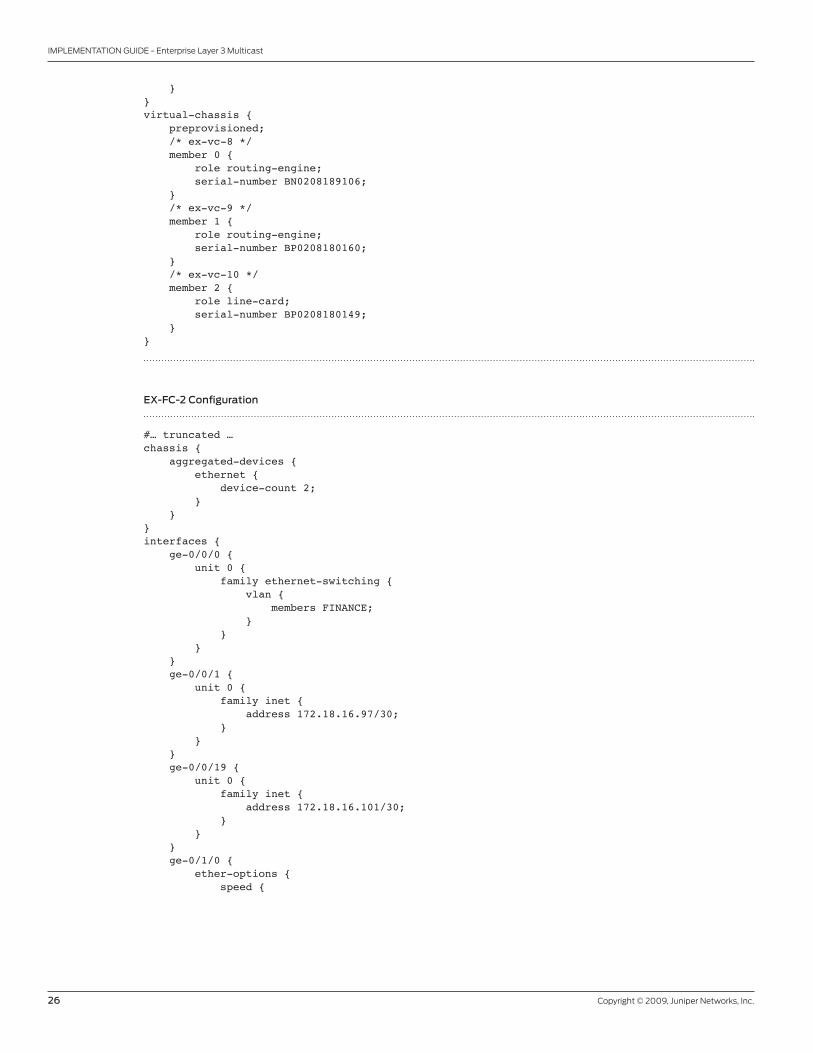
EX-FC-2 Configuration
#…truncated…chassis{aggregated-devices{ethernet{device-count2;}}}interfaces{ge-0/0/0{unit0{familyethernet-switching{vlan{membersFINANCE;}}}}ge-0/0/1{unit0{familyinet{address172.18.16.97/30;}}}ge-0/0/19{unit0{familyinet{address172.18.16.101/30;}}}ge-0/1/0{ether-options{speed{

Copyright © 2009, Juniper Networks, Inc. 27
IMPLEMENTATION GUIDE - Enterprise Layer 3 Multicast
1g;}802.3adae0;}}ge-0/1/1{ether-options{speed{1g;}802.3adae1;}}ge-0/1/2{ether-options{speed{1g;}802.3adae0;}}ge-0/1/3{ether-options{speed{1g;}802.3adae1;}}ae0{unit0{familyinet{address172.18.16.70/30;}}}ae1{unit0{familyinet{address172.18.16.78/30;}}}lo0{unit0{familyinet{address172.18.12.2/32;}}}me0{unit0{familyinet{address172.19.59.208/24;}}}vlan{unit500{familyinet{

28 Copyright © 2009, Juniper Networks, Inc.
IMPLEMENTATION GUIDE - Enterprise Layer 3 Multicast
address172.18.14.1/24;}}}}routing-options{graceful-restart;router-id172.18.12.2;}protocols{ igmp; # Explicitly enables IGMPospf{area0.0.0.2{stubdefault-metric10;interfaceae0.0{authentication{simple-password“$9$U-iqf36A1RSTzRSreXxDikmQF”;##SECRET-DATA}bfd-liveness-detection{minimum-interval300;}}interfaceae1.0{authentication{simple-password“$9$2roZjmfzCtOHqtO1RlegoJUk.”;##SECRET-DATA}bfd-liveness-detection{minimum-interval300;}}interfaceme0.0{disable;}interfacelo0.0{passive;}interfacevlan.500{passive;}interfacege-0/0/1.0{authentication{simple-password“$9$Qbiw3/t1RSM87uO87-V4oz36C0B”;##SECRET-DATA}bfd-liveness-detection{minimum-interval300;}}interfacege-0/0/19.0{passive;}}}pim { rp { # Configuration of anycast-PIM on non-RP devices static { address 172.18.19.254; # Uses the shared anycast address as the RP address } } interface all { mode sparse; # Sets all interfaces to PIM sparse mode

Copyright © 2009, Juniper Networks, Inc. 29
IMPLEMENTATION GUIDE - Enterprise Layer 3 Multicast
} interface me0.0 { disable; # Explicitly disables PIM on the management interface } } igmp-snooping { vlan FINANCE; # Enables IGMP snooping for vlan FINANCE}stp{disable;}rstp{disable;}}vlans{FINANCE{vlan-id500;l3-interfacevlan.500;}}
MX-A Configuration
#…truncated…chassis{redundancy{graceful-switchover;}aggregated-devices{ethernet{device-count4;}}fpc 5 { # Required to create tunnel interface to de-encapsulate PIM register messages pic 0 { tunnel-services { bandwidth 1g; } } }}interfaces{ge-5/0/0{gigether-options{802.3adae0;}}ge-5/0/1{gigether-options{802.3adae1;}}ge-5/0/2{gigether-options{802.3adae2;}}

30 Copyright © 2009, Juniper Networks, Inc.
IMPLEMENTATION GUIDE - Enterprise Layer 3 Multicast
ge-5/0/3{gigether-options{802.3adae3;}}ge-5/0/4{gigether-options{802.3adae0;}}ge-5/0/5{gigether-options{802.3adae1;}}ge-5/0/6{gigether-options{802.3adae2;}}ge-5/0/7{gigether-options{802.3adae3;}}ge-5/0/8{unit0{familyinet{address172.18.16.129/30;}}}ge-5/0/9{unit0{familyinet{address172.18.16.133/30;}}}ge-5/1/0{unit0{familyinet{address172.18.16.141/30;}}}ae0{unit0{familyinet{address172.18.16.1/30;}}}ae1{unit0{familyinet{address172.18.16.5/30;}}}

Copyright © 2009, Juniper Networks, Inc. 31
IMPLEMENTATION GUIDE - Enterprise Layer 3 Multicast
ae2{unit0{familyinet{address172.18.16.65/30;}}}ae3{unit0{familyinet{address172.18.16.69/30;}}}lo0 { unit 0 { family inet { address 172.18.19.1/32 { primary; } address 172.18.19.254/32; # Loopback address used as shared anycast address } } }}routing-options{graceful-restart;static{route200.0.1.0/24reject;route200.0.2.0/24reject;}router-id172.18.19.1;}protocols{ospf{exportstat;area0.0.0.1{stubdefault-metric10;area-range172.18.8.0/22;area-range172.18.16.0/26;interfaceae0.0{authentication{simple-password“$9$0fRe1EyM87s2alK2aZU.mO1RhlK”;##SECRET-DATA}bfd-liveness-detection{minimum-interval300;}}interfaceae1.0{authentication{simple-password“$9$-PbYoDi.z39JG39ApREdbs2JG”;##SECRET-DATA}bfd-liveness-detection{minimum-interval300;}}}area0.0.0.2{stubdefault-metric10;area-range172.18.12.0/22;

32 Copyright © 2009, Juniper Networks, Inc.
IMPLEMENTATION GUIDE - Enterprise Layer 3 Multicast
area-range172.18.16.64/26;interfaceae2.0{authentication{simple-password“$9$1dIESeLxdgoGvWoGDif5IEcrM8”;##SECRET-DATA}bfd-liveness-detection{minimum-interval300;}}interfaceae3.0{authentication{simple-password“$9$5znCO1hKMXtuMX7-2gTz3/p0”;##SECRET-DATA}bfd-liveness-detection{minimum-interval300;}}}area0.0.0.0{interfacege-5/0/8.0{authentication{md510key“$9$zNHSn9pIEyWLN0BLNdboaFn/9uO”;##SECRET-DATA}}interfacege-5/0/9.0{authentication{md510key“$9$aPGjqTz6uORmfORhSMWJGDj.P”;##SECRET-DATA}}interfacelo0.0{passive;}interfacefxp0.0{disable;}interfacege-5/1/0.0{passive;}}}pim { rp { # Configuration of anycast-PIM on RP devices local { family inet { address 172.18.19.254; # Anycast-PIM address shared by the RPs anycast-pim { rp-set { address 172.18.19.2; # Local address of the other RP } local-address 172.18.19.1; # Local address of this RP } } } } interface all { mode sparse; # Sets all interfaces to PIM sparse mode } interface fxp0.0 { disable; # Explicitly disables PIM on the management interface }

Copyright © 2009, Juniper Networks, Inc. 33
IMPLEMENTATION GUIDE - Enterprise Layer 3 Multicast
}}policy-options{policy-statementstat{fromprotocolstatic;thenaccept;}}
MX-B Configuration
#…truncated…chassis{redundancy{graceful-switchover;}aggregated-devices{ethernet{device-count4;}} fpc 2 { # Required to create tunnel interface to de-encapsulate PIM register messages pic 0 { tunnel-services { bandwidth 1g; } } }}interfaces{ge-2/0/0{gigether-options{802.3adae0;}}ge-2/0/1{gigether-options{802.3adae1;}}ge-2/0/2{gigether-options{802.3adae2;}}ge-2/0/3{gigether-options{802.3adae3;}}ge-2/0/4{gigether-options{802.3adae0;}}ge-2/0/5{gigether-options{802.3adae1;

34 Copyright © 2009, Juniper Networks, Inc.
IMPLEMENTATION GUIDE - Enterprise Layer 3 Multicast
}}ge-2/0/6{gigether-options{802.3adae2;}}ge-2/0/7{gigether-options{802.3adae3;}}ge-2/0/8{unit0{familyinet{address172.18.16.130/30;}}}ge-2/0/9{unit0{familyinet{address172.18.16.137/30;}}}ae0{unit0{familyinet{address172.18.16.9/30;}}}ae1{unit0{familyinet{address172.18.16.13/30;}}}ae2{unit0{familyinet{address172.18.16.73/30;}}}ae3{unit0{familyinet{address172.18.16.77/30;}}}lo0 { unit 0 { family inet { address 172.18.19.2/32 { primary; } address 172.18.19.254/32; # Loopback address used as shared anycast address

Copyright © 2009, Juniper Networks, Inc. 35
IMPLEMENTATION GUIDE - Enterprise Layer 3 Multicast
} } }}routing-options{graceful-restart;static{route200.0.1.0/24reject;route200.0.2.0/24reject;}router-id172.18.19.2;}protocols{ospf{exportstat;area0.0.0.1{stubdefault-metric10;area-range172.18.8.0/22;area-range172.18.16.0/26;interfaceae0.0{authentication{simple-password“$9$d6w2ajHmFnCZUnCtuEhVwYgZU”;##SECRET-DATA}bfd-liveness-detection{minimum-interval300;}}interfaceae1.0{authentication{simple-password“$9$AXE/uBElK8db2cyb24aiHtuO1cy”;##SECRET-DATA}bfd-liveness-detection{minimum-interval300;}}}area0.0.0.2{stubdefault-metric10;area-range172.18.12.0/22;area-range172.18.16.64/26;interfaceae2.0{authentication{simple-password“$9$m5z6p0IreW9AeWLxwsP5Q3Ct”;##SECRET-DATA}bfd-liveness-detection{minimum-interval300;}}interfaceae3.0{authentication{simple-password“$9$hRNyeWNdsJGiLxGik.zFcylvX7”;##SECRET-DATA}bfd-liveness-detection{minimum-interval300;}}}area0.0.0.0{interfacege-2/0/8.0{authentication{md510key“$9$MKTL7VgoGqmTwYmTz3tpWLx7bs”;##SECRET-DATA}}

36 Copyright © 2009, Juniper Networks, Inc.
IMPLEMENTATION GUIDE - Enterprise Layer 3 Multicast
interfacege-2/0/9.0{authentication{md510key“$9$m5z6p0IreW9AeWLxwsP5Qz/C”;##SECRET-DATA}}interfacelo0.0{passive;}interfacefxp0.0{disable;}}}pim { traceoptions { # Traceoptions for PIM troubleshooting file pim; flag join detail; flag task detail; flag state detail; flag packets detail; } rp { # Uses the shared anycast address as the RPs address local { family inet { address 172.18.19.254; # Anycast-PIM address shared by the RPs anycast-pim { rp-set { address 172.18.19.1; # Local address of the other RP } local-address 172.18.19.2; # Local address of this RP } } } } interface all { mode sparse; # Sets all interfaces to PIM sparse mode } interface fxp0.0 { disable; # Explicitly disables PIM on the management interface } }}policy-options{policy-statementstat{fromprotocolstatic;thenaccept;}}
Juniper Networks M120 Multiservice Edge Router Configuration
#…truncated…chassis{redundancy{graceful-switchover;}}interfaces{ge-5/0/0{unit0{familyinet{

Copyright © 2009, Juniper Networks, Inc. 37
IMPLEMENTATION GUIDE - Enterprise Layer 3 Multicast
address172.18.16.134/30;}}}ge-5/0/1{unit0{familyinet{address172.18.16.138/30;}}}lo0{unit0{familyinet{address172.18.19.3/32{primary;}}}}}routing-options{graceful-restart;router-id172.18.19.3;}protocols{ospf{area0.0.0.0{interfacege-5/0/0.0{authentication{md510key“$9$aLGjqTz6uORmfORhSMWJGDj.P”;##SECRET-DATA}}interfacege-5/0/1.0{authentication{md510key“$9$.fQntu1ylM/ClM8XbwmfTQ69”;##SECRET-DATA}}interfacelo0.0{passive;}interfacefxp0.0{disable;}}}pim { rp { # Configuration of anycast-PIM on non-RP devices static { address 172.18.19.254; # Uses the shared anycast address as the RP address } } interface all { mode sparse; # Sets all interfaces to PIM sparse mode } interface fxp0.0 { disable; # Explicitly disables PIM on the management interface } }}

38 Copyright © 2009, Juniper Networks, Inc.
IMPLEMENTATION GUIDE - Enterprise Layer 3 Multicast
Verification
This section lists some commands that can be used to verify the multicast setup along with sample outputs:
General Multicast
Show Multicast RPF
This command displays information about the PIM RPF table similar to what can be seen in the routing table. The
source prefix, the protocol, the upstream interface and the neighbor that it was learned from are all displayed:
lab@ex-vc-1>showmulticastrpfMulticastRPFtable:inet.0,33entries
0.0.0.0/0Protocol:OSPFInterface:ae1.0Neighbor:172.18.16.9
172.18.8.1/32Protocol:DirectInterface:lo0.0
#…truncated…
224.0.0.2/32Protocol:PIM
224.0.0.5/32Protocol:OSPF
224.0.0.13/32Protocol:PIM
224.0.0.22/32Protocol:IGMP
MulticastRPFtable:inet6.0,2entries
ff02::2/128Protocol:PIM
ff02::d/128Protocol:PIM
{master:0}
Show Multicast Route Extensive
This command can be used to examine the multicast routing table that acts as a cache and is based on both IGMP
group activity and RPF information. Note “show route table inet.1 extensive” can also be used to examine this table.
lab@ex-vc-1>showmulticastrouteextensive
Group:225.0.0.1Source:172.18.16.102/32Upstreaminterface:ae0.0Downstreaminterfacelist:vlan.100Sessiondescription:MALLOCStatistics:0kBps,0pps,3209packetsNext-hopID:131070

Copyright © 2009, Juniper Networks, Inc. 39
IMPLEMENTATION GUIDE - Enterprise Layer 3 Multicast
Upstreamprotocol:PIMRoutestate:ActiveForwardingstate:ForwardingCachelifetime/timeout:360secondsWrongincominginterfacenotifications:10
Group:225.0.0.1Source:172.18.16.142/32Upstreaminterface:ae0.0Downstreaminterfacelist:vlan.100Sessiondescription:MALLOCStatistics:0kBps,0pps,3184packetsNext-hopID:131070Upstreamprotocol:PIMRoutestate:ActiveForwardingstate:ForwardingCachelifetime/timeout:360secondsWrongincominginterfacenotifications:1
{master:0}
Show Multicast Usage
lab@ex-vc-1>showmulticastusageGroupSourcesPacketsBytes225.0.0.12640353998
Prefix/lenGroupsPacketsBytes172.18.16.102/321321427574172.18.16.142/321318926424
{master:0}
Show Multicast Next-Hops
lab@ex-vc-1>showmulticastnext-hopsFamily:INETIDRefcountKRefcountDownstreaminterface13107042vlan.100
Family:INET6
{master:0}
PIM
Show PIM RPS Extensive
This command displays information about RPs, how they were learned, the group range they handle, and the ones that
are currently active. In the example below, since this is the RP, the output also includes anycast PIM RP information.
The configuration of a tunnel PIC on this MX Series device resulted in the creation of a de-encapsulation interface
that allows the RP to receive multicast traffic from the source. This interface is indicated by pd-5/0/10.32769 in the
example below.

40 Copyright © 2009, Juniper Networks, Inc.
IMPLEMENTATION GUIDE - Enterprise Layer 3 Multicast
lab@Madras-MX-A>showpimrpsextensiveInstance:PIM.masterAddressfamilyINET
RP:172.18.19.254Learnedvia:staticconfigurationTimeActive:1w2d16:09:14Holdtime:0DeviceIndex:153Subunit:32769Interface:pd-5/0/10.32769GroupRanges:224.0.0.0/4RegisterStateforRP:GroupSourceFirstHopRPAddressStateTimeout225.0.0.1172.18.16.102172.18.19.2172.18.19.254Receive261225.0.0.2172.18.16.102172.18.19.2172.18.19.254Receive281225.0.0.3172.18.16.102172.18.19.2172.18.19.254Receive0AnycastPIMrpset:172.18.19.2AnycastPIMlocaladdressused:172.18.19.1AnycastPIMRegisterState:GroupSourceOrigin225.0.0.1172.18.16.142DIRECT225.0.0.2172.18.16.142DIRECT225.0.0.3172.18.16.142DIRECT
AddressfamilyINET6
{master}
Show PIM Interface
Use this command to list the currently configured and operational interfaces for PIM. As shown in the example below,
this includes the name of each interface, its operational state (up/down), its mode (sparse, dense, or sparse-dense),
the IP version supported (IPv4 in this case), the PIM version (2 by default), the current state of the interface, the
neighbor count, the join count, and the designated router address.
If the interface is responsible for forwarding traffic, the state shows as “DR”. If it is not responsible for forwarding traffic,
it shows as “NotDR”. Note that this command also shows the de-encapsulation interface (pd-5/0/10.32769) which is a
non-broadcast interface as indicated by its state (point to point).
lab@Madras-MX-A>showpiminterfaces
Instance:PIM.master
NameStat ModeIPV State NbrCnt JoinCnt DRaddress
ae0.0Up Sparse42 NotDR 1 0 172.18.16.2
ae1.0Up Sparse42 NotDR 1 0 172.18.16.6
ae2.0Up Sparse42 NotDR 1 1 172.18.16.66
ae3.0Up Sparse42 NotDR 1 3 172.18.16.70
ge-5/0/8.0Up Sparse42 NotDR 1 0 172.18.16.130
ge-5/0/9.0Up Sparse42 NotDR 1 0 172.18.16.134
ge-5/1/0.0Up Sparse42 DR 0 0 172.18.16.141
lo0.0Up Sparse42 DR 0 0 172.18.19.1
pd-5/0/10.32769UpSparse42 P2P 0 0
{master}
Copyright © 2009, Juniper Networks, Inc. 41
IMPLEMENTATION GUIDE - Enterprise Layer 3 Multicast
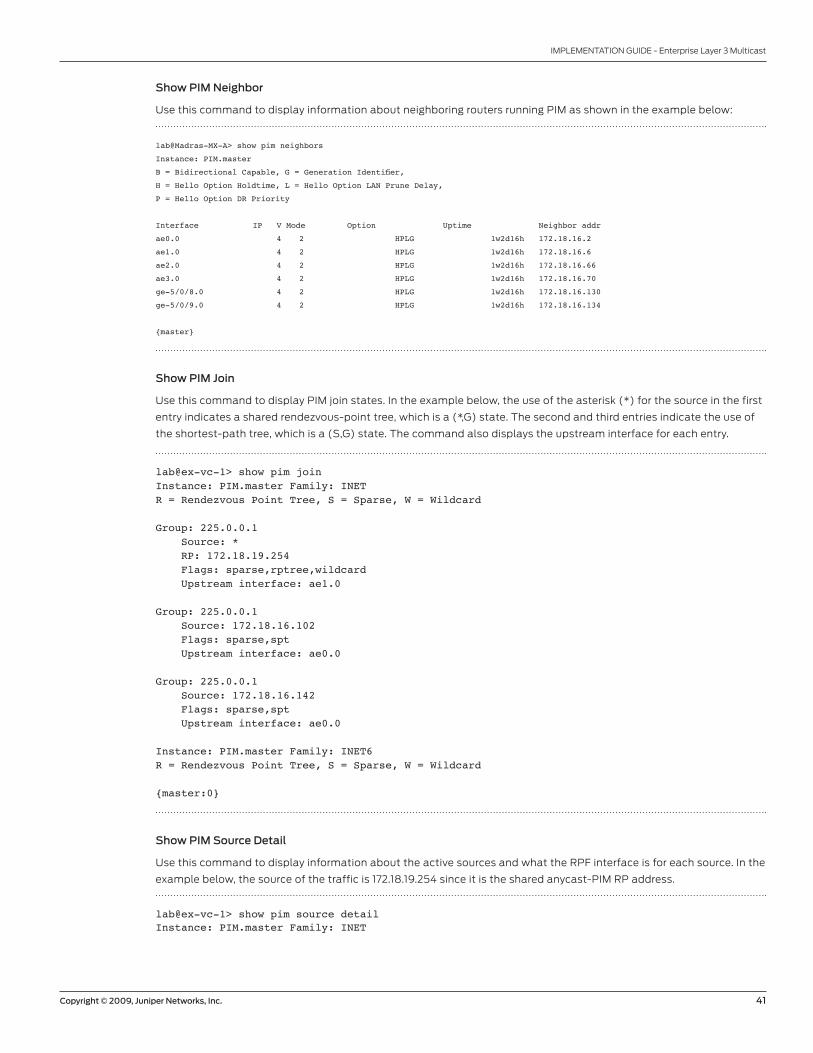
Show PIM Neighbor
Use this command to display information about neighboring routers running PIM as shown in the example below:
lab@Madras-MX-A>showpimneighbors
Instance:PIM.master
B=BidirectionalCapable,G=GenerationIdentifier,
H=HelloOptionHoldtime,L=HelloOptionLANPruneDelay,
P=HelloOptionDRPriority
InterfaceIP VModeOption Uptime Neighboraddr
ae0.0 4 2 HPLG 1w2d16h 172.18.16.2
ae1.0 4 2 HPLG 1w2d16h 172.18.16.6
ae2.0 4 2 HPLG 1w2d16h 172.18.16.66
ae3.0 4 2 HPLG 1w2d16h 172.18.16.70
ge-5/0/8.0 4 2 HPLG 1w2d16h 172.18.16.130
ge-5/0/9.0 4 2 HPLG 1w2d16h 172.18.16.134
{master}
Show PIM Join
Use this command to display PIM join states. In the example below, the use of the asterisk (*) for the source in the first
entry indicates a shared rendezvous-point tree, which is a (*,G) state. The second and third entries indicate the use of
the shortest-path tree, which is a (S,G) state. The command also displays the upstream interface for each entry.
lab@ex-vc-1>showpimjoinInstance:PIM.masterFamily:INETR=RendezvousPointTree,S=Sparse,W=Wildcard
Group:225.0.0.1Source:*RP:172.18.19.254Flags:sparse,rptree,wildcardUpstreaminterface:ae1.0
Group:225.0.0.1Source:172.18.16.102Flags:sparse,sptUpstreaminterface:ae0.0
Group:225.0.0.1Source:172.18.16.142Flags:sparse,sptUpstreaminterface:ae0.0
Instance:PIM.masterFamily:INET6R=RendezvousPointTree,S=Sparse,W=Wildcard
{master:0}
Show PIM Source Detail
Use this command to display information about the active sources and what the RPF interface is for each source. In the
example below, the source of the traffic is 172.18.19.254 since it is the shared anycast-PIM RP address.
lab@ex-vc-1>showpimsourcedetailInstance:PIM.masterFamily:INET

42 Copyright © 2009, Juniper Networks, Inc.
IMPLEMENTATION GUIDE - Enterprise Layer 3 Multicast
Source172.18.19.254Prefix172.18.19.254/32Upstreaminterfaceae1.0Upstreamneighbor172.18.16.9Activegroups:225.0.0.1
Instance:PIM.masterFamily:INET6
{master:0}
Show PIM Statistics
This command displays PIM-related messages and error counts as shown in the example below:
lab@Madras-MX-A>showpimstatistics
PIMMessagetypeReceivedSentRxerrorsV2Hello1759252052600V2Register41580415610V2RegisterStop41542415360V2JoinPrune41655138630V2Bootstrap000V2Assert000V2Graft000V2GraftAck000V2CandidateRP000V1Query000V1Register000V1RegisterStop000V1JoinPrune000V1RPReachability000V1Assert000V1Graft000V1GraftAck000AutoRPAnnounce000AutoRPMapping000AutoRPUnknowntype0AnycastRegister41526415610AnycastRegisterStop41542415290
GlobalStatistics
Hellodroppedonneighborpolicy0Unknowntype0V1Unknowntype0UnknownVersion0Neighborunknown0BadLength0BadChecksum0BadReceiveIf0RxBadData0RxIntfdisabled0RxV1RequireV20RxV2RequireV10RxRegisternotRP0RxRegisternoroute0RxRegisternodecapif0NullRegisterTimeout0RPFilteredSource0RxUnknownRegStop0RxJoin/Prunenostate0RxJoin/Pruneonupstreamif0Rxsparsejoinfordensegroup0RxGraft/GraftAcknostate0

Copyright © 2009, Juniper Networks, Inc. 43
IMPLEMENTATION GUIDE - Enterprise Layer 3 Multicast
RxGraftonupstreamif0RxCRPnotBSR0RxBSRwhenBSR0RxBSRnotRPFif0Rxunknownhelloopt0Rxdatanostate0RxRPnostate0Rxaggregate0Rxmalformedpacket0NoRP0Noregisterencapif0Norouteupstream0NexthopUnusable0RPmismatch0RPFneighborunknown0RxJoins/Prunesfiltered0Embedded-RPinvalidaddr0Embedded-RPlimitexceed0Embedded-RPadded0Embedded-RPremoved0RxRegistermsgsfilteringdrop0TxRegistermsgsfilteringdrop0
{master}
IGMP
Show IGMP Interface
This command lists information about the interfaces running IGMP including their state, the IGMP querier address,
the IGMP version, and the number of groups currently active. It also lists the derived and configured timer and counter
parameters for IGMP (all use the default values in the example below).
lab@ex-vc-1>showigmpinterfaceInterface:ae0.0Querier:172.18.16.1State:UpTimeout:166Version:2Groups:0Immediateleave:OffPromiscuousmode:OffInterface:ae1.0Querier:172.18.16.9State:UpTimeout:167Version:2Groups:0Immediateleave:OffPromiscuousmode:OffInterface:vlan.100Querier:172.18.9.1State:UpTimeout:NoneVersion:2Groups:1Immediateleave:OffPromiscuousmode:OffInterface:ge-0/0/2.0Querier:172.18.16.33State:UpTimeout:NoneVersion:2Groups:0Immediateleave:OffPromiscuousmode:Off

44 Copyright © 2009, Juniper Networks, Inc.
IMPLEMENTATION GUIDE - Enterprise Layer 3 Multicast
ConfiguredParameters:IGMPQueryInterval:125.0IGMPQueryResponseInterval:10.0IGMPLastMemberQueryInterval:1.0IGMPRobustnessCount:2
DerivedParameters:IGMPMembershipTimeout:260.0IGMPOtherQuerierPresentTimeout:255.0
{master:0}
Show IGMP Group
Use this command to show the groups joined by directly connected hosts and other routers. Note that if IGMP is
explicitly enabled but PIM is not enabled on an interface, the status of that interface is shown as “Up” but is omitted
from the output of the “show igmp group”.
lab@ex-vc-1>showigmpgroupInterface:vlan.100Group:225.0.0.1Source:0.0.0.0Lastreportedby:172.18.9.2Timeout:187Type:DynamicInterface:localGroup:224.0.0.2Source:0.0.0.0Lastreportedby:LocalTimeout:0Type:DynamicGroup:224.0.0.5Source:0.0.0.0Lastreportedby:LocalTimeout:0Type:DynamicGroup:224.0.0.6Source:0.0.0.0Lastreportedby:LocalTimeout:0Type:DynamicGroup:224.0.0.22Source:0.0.0.0Lastreportedby:LocalTimeout:0Type:Dynamic
{master:0}
Show IGMP Statistics
This command displays IGMP-related messages and error counts as shown in the example below:
lab@ex-vc-1>showigmpstatisticsIGMPpacketstatisticsforallinterfacesIGMPMessagetypeReceivedSentRxerrorsMembershipQuery13425134360V1MembershipReport000DVMRP000PIMV1000CiscoTrace000V2MembershipReport733500GroupLeave000MtraceResponse000MtraceRequest000

Copyright © 2009, Juniper Networks, Inc. 45
IMPLEMENTATION GUIDE - Enterprise Layer 3 Multicast
DomainWideReport000V3MembershipReport000OtherUnknowntypes0IGMPv3unsupportedtype0IGMPv3sourcerequiredforSSM0IGMPv3modenotapplicableforSSM0
IGMPGlobalStatisticsBadLength0BadChecksum0BadReceiveIf0Rxnon-local0Timedout619RejectedReport0TotalInterfaces4
{master:0}{master:0}
Show IGMP Snooping Membership
The IGMP snooping cache can be displayed through “show igmp-snooping membership” command as shown below:
lab@ex-vc-1>showigmp-snoopingmembershipVLAN:HR225.0.0.1*171secsInterfaces:ge-0/0/23.0
{master:0}
Show IGMP Snooping Route Ethernet Switching
The forwarding state that is generated can be seen through “show igmp-snooping route ethernet-switching”:
lab@ex-vc-1>showigmp-snoopingrouteethernet-switchingVLANGroupNext-hopHR224.0.0.0,*HR225.0.0.1,*1309
{master:0}
Show IGMP Snooping Statistics
This command shows message and error counts related to IGMP snooping:
lab@ex-vc-1>showigmp-snoopingstatisticsBadlength:0Badchecksum:0Invalidinterface:0Notlocal:0Receiveunknown:0Timedout:0
IGMPTypeReceivedTransmitedRecvErrorsQueries:020Reports:671600Leaves:000Other:000
{master:0}

46 Copyright © 2009, Juniper Networks, Inc.
IMPLEMENTATION GUIDE - Enterprise Layer 3 Multicast
Show IGMP Snooping VLANS
lab@ex-vc-1>showigmp-snoopingvlansdetailVLAN:HR,Tag:100,vlan-interface:vlan.100Membershiptimeout:260,Queriertimeout:255Interface:ge-0/0/0.0,untagged,Groups:0,Reporters:0Interface:ge-0/0/23.0,untagged,Groups:1,Reporters:1
{master:0}
Troubleshooting
Confirming the Presence of De-Encapsulation (pd) or Encapsulation (pe) Interfaces
• Show interfaces terse | match “pd|pe”
Verifying Multicast Routes in Forwarding Table
• Show route forwarding-table multicast destination <prefix>
• Request pfe execute target <fpc> command “sh nhdb id <id> ext”
Clearing Statistics and Usage
• Clear pim join
• Clear multicast statistics
• Clear multicast usage
• Clear IGMP statistics
• Clear IGMP snooping membership
• Clear IGMP snooping statistics
Trace Options
• Set protocols pim traceoptions flag hello detail
• Set protocols pim traceoptions flag join detail
• Set protocols pim traceoptions flag prune detail
• Set protocols pim traceoptions flag packets detail
• Set protocols pim traceoptions flag state detail
• Set protocols pim traceoptions flag task detail
• Set protocols igmp traceoptions flag query detail
• Set protocols igmp traceoptions flag report detail
• Set protocols igmp traceoptions flag leave detail (IGMP version 2 only)
• Set protocols igmp traceoptions flag packets detail
• Set protocols igmp-snooping traceoptions flag query detail
• Set protocols igmp-snooping traceoptions flag report detail
• Set protocols igmp-snooping traceoptions flag leave detail (IGMP version 2 only)
• Set protocols igmp-snooping traceoptions flag packets detail

Copyright © 2009, Juniper Networks, Inc. 47
IMPLEMENTATION GUIDE - Enterprise Layer 3 Multicast
Summary
Juniper Networks provides enterprise customers with a variety of solutions to implement multicast forwarding based on
their specific requirements to deliver applications such as interactive distance learning, corporate video conferencing,
inventory updates, software, and content distribution. This document provided a brief overview of some of the options
that Junos OS offers and presented the pros and cons of each. It then presented implementation guidelines for IP
multicast deployments in enterprise networks using the EX Series Ethernet Switches and MX Series 3D Universal Edge
Routers and two core multicast protocols: PIM sparse mode and IGMPv2. Finally, an implementation example was
presented with detailed configurations, verifications, and troubleshooting procedures.
Appendixes
Appendix A: Conventions/Glossary
BSR Bootstrap router
Candidate RP Candidate RP
DPC Dense Port Concentrator
DVMRP Distance Vector Multicast Routing Protocol
FPC Flexible PIC Concentrator
IGMP Internet Group Management Protocol
MSDP Multicast Source Discovery Protocol
OSPF Open Shortest Path First
PIC Physical Interface Card
PIM Protocol Independent Multicast
PIM DM PIM dense mode
PIM SM PIM sparse mode
PIM SSM PIM source-specific multicast
P2P Point to point
RE Routing Engine
RP Rendezvous point
RPF Reverse path forwarding
SFP Small form-factor pluggable transceiver
SPT Shortest-path tree
VC Virtual Chassis
VCP Virtual Chassis Port
VLAN Virtual LAN

8010062-001-EN Dec 2009
Copyright 2009 Juniper Networks, Inc. All rights reserved. Juniper Networks, the Juniper Networks logo, Junos, NetScreen, and ScreenOS are registered trademarks of Juniper Networks, Inc. in the United States and other countries. All other trademarks, service marks, registered marks, or registered service marks are the property of their respective owners. Juniper Networks assumes no responsibility for any inaccuracies in this document. Juniper Networks reserves the right to change, modify, transfer, or otherwise revise this publication without notice.
EMEA Headquarters
Juniper Networks Ireland
Airside Business Park
Swords, County Dublin, Ireland
Phone: 35.31.8903.600
EMEA Sales: 00800.4586.4737
Fax: 35.31.8903.601
APAC Headquarters
Juniper Networks (Hong Kong)
26/F, Cityplaza One
1111 King’s Road
Taikoo Shing, Hong Kong
Phone: 852.2332.3636
Fax: 852.2574.7803
Corporate and Sales Headquarters
Juniper Networks, Inc.
1194 North Mathilda Avenue
Sunnyvale, CA 94089 USA
Phone: 888.JUNIPER (888.586.4737)
or 408.745.2000
Fax: 408.745.2100
www.juniper.net
To purchase Juniper Networks solutions,
please contact your Juniper Networks
representative at 1-866-298-6428 or
authorized reseller.
Printed on recycled paper
48 Copyright © 2009, Juniper Networks, Inc.
IMPLEMENTATION GUIDE - Enterprise Layer 3 Multicast
About Juniper Networks
Juniper Networks, Inc. is the leader in high-performance networking. Juniper offers a high-performance network
infrastructure that creates a responsive and trusted environment for accelerating the deployment of services and
applications over a single network. This fuels high-performance businesses. Additional information can be found at
www.juniper.net.