enterprise management network architecture distrubuted ...enterprise management network architecture...
TRANSCRIPT

Enterprise Management Network Architecture Distributed Knowledge Base Support
Michel Roboam, Mark S . Fox and Katia Sycara
CMU-RI-TR-90-21
Center for Integrated Manufacturing Decision Systems The Robotics Institute
Camegie Mellon University Pittsburgh, Pennsylvania 15213
November 1990
0 1990 Camegie Mellon University
Michel Roboam is currently visiting scientist in the Center for Integrated Manufacturing Decision Systems and is sponsored by the AEROSPATW Company (France).
This research has been supported, in part, by the Defense Advance Research Projects Agency under conmct #F30602-88-C-OM)l, and in part by grants from McDonnell Aircraft Company and Digital Ruipment Corporation.

i
Table of Contents 1. Introduction 2. Distributed Systems Definition
2.1 Distributed Syetems Advantages 2.2 Decentralized Systems toplevel description 2.3 Distributed System Dimensions
2.3.1 Parallel Distributed Processing Systems 25% Distributed Problem Solving Systems Definition
2.4 Distributed Systems capabilities 2.5 Distributed Systems Problems
3. Enterprise Management Network Node 4. Network Layer
4.1 Introduction 4.2 Network Specification 4.3 EMN-node specification
45.1 Schemata supporting EMN-nodea initialization 4.33 Functions eupporting EMN-nodes initialieation 4.33 Example dEMN-node initialization
4.4.1 Schemata supporting the communication pmcedures 4.4.2 Functions supporting the communication procedures 4.43 Example of communication funetion implementation
4.4 Communication Procedures
4.4.3.1 Message passing without blocking 4 A 5 3 Messape reception 4.453 Message passing with blocking
4.5 Network Layer example
5.1 Introduction 522Schematamanipulated
63.1 The information schema 6.2.2 The message schema 6.23 The answer schema 6.2AThe communication schema
5. Data Layer
5.3 Information consistency checking primitives 5.4 Query language
6.4.1 Complete schema request 6.43 Simple retrieval 5.43 Qualified retriwal 6-44 Retrieval Gth ordering 6.4.6 Retrieval from more than one Bchema 5.4.6 &tr ied involving queries within queries 6.4.7 Locking and UnIocking mechanism
5.5 Data Layer example 6. Information Layer
6.1 Introduction 6.2 Access privilege granting 6.3 Automatic information acquisition 6.4 Automatic information management 6.5 Information Layer example 6.6 Information Layer Implementation
8.8.1 Information distribution 6.63 The message generation sequence 6.63 The updating activity 6.6-4 The message and answer reception sequence
1 4 4 4 5 5 6 6 7 8
12 12 13 13 13 18 16 19 19 20 21 22 24 25 29 30 30 31 32 33 38 39 44 46 47 47 47 60 62 63 64 55 56 56 57 59 61 62 63 84 69 73 76

ii
8.6A.1 The message reception sequence 6.6.4.2 The answer reception sequence
6.7 Information Lager utilization example 7. Conclusion Acknowledgement Referencea
78 79 81 83 85 86

iii
List of Figures Figure 3-1: Example of decentralized system Figure 3-2 The elements of an EMN-node Figure 3.3: Information exchanges overview Figure 34: Decentralized system example Figure 4-1: Message passing algorithm Figure 4-2: Message passing steps Figure 43 Checking mail box algorithm Figure 4 4 Message reception step Figure 46: Message passing with blocking. step 1 Figure 4-6 Message passing with blockins step 2 Figure 41: Message passing with bl-. step 3 Figure 4-8: Message passing with blocking. step 4 Figure 4-S: Network Layer implementation example Figure 5.1: Query elements Figure 6-2 Object flow representation Figure 5-3 Decentralized Knowledge Craft lu~ullll ‘ g Figure 54: Mutual table consistency checking Figure 5-5: Information flows representation Figure 543 Data Layer implementation example Figure 6-1: Information Layer implementation example Figure 6-2: Information distribution sequence Figure 6-3 Hierarchical distribution example Figure 64. Distribution sequence for an EMN-node initialization Figure 6-5: Distribution message reception Figure 6-6: Message generation sequence Figure 6-1: Updating message generation sequence Figure 6-8: Message and answer reception sequence Figure 6-9 Answer control sequence
8 9 10 11 22 23 24 25 26 27 27
29 30 32 40 45 46 55 63 65 66 67 69 70 75 77 so
28

List of Schemata Schema 41: Network Schema 4-2 DKCSystem Schema 4-3: DKC-Channel Schema 4-4: 1ocaLDKC-Channel Schema 45: Agent-1-DKC-System Schema 4-8: agent-1-DKC-local-ChaMel Schema 4-1: agent-ZDKC-Channel Schema 4-8. Agent-1-DKC-System Schema 4-9 DKC-message Schema 4-10: DKC-queued-message Schema 51: Information Schema62 Message Schema 53: Information-search-meeeage Schema 5-4: Updathg-message Schema 65 LC-distribution-message Schema 5-6: UT-distribution-message Schema 67: distribution-END-message Schema- Answer Schema&% Answerexample Schema 610 Communication Schema 5-11: Communication Schema6-1: CLASS Schema 65: NO-SCHEMA-SPEC Schema 6-3: NO-SLOT-SPEC Schema 6-4: NO-VALUE-SPEC Schema 6-5: Answer-message Schema 6-6 Message-queue Schema 6-1: New-message Schema 6-8: Control-answer Schema 6-9 Answerqueue Schema 6-10 New-answer
13 14 15 15 17 17 18 18 19 20 33 34 35 36 36 37 37 38 39 41 42 64 71 72 73 78 78 78 79 79 81

Abstract
Achieving manufacturing efficiency requires that many groups that comprise a manufacturing enterprise, such as design, planning, production, distribution, field service, accounting, sales and marketing, cooperate in order to achieve their mmmon goal. In this paper we introduce the concept of Enterprise Management Network (EMN) as the element to facilitate the integration of distributed heterogeneous functions of a manufacturing enterprise. The integration is supported by having the network first play a more active role in the accessing and communication of information, and second provide the appropriate protocols for the distribution, coordination, and negotiation of tasks and outcomes. The EMN is divided into six layers: Network Layer, Data Layer, Information Layer, Organization Layer, Coordination Layer, and Market Layer. Each of these layers provides a portion of the elemente, functions and protocols to allow the integration d a manufacturing enterprise.

1
1. Introduction This report presenta the architecture, the elements and the organization of an Enterprise
Management Network (E.M.N.) to support the integration of the manufacturing enterprise. The optimization of the manufacturing enterprise can only be achieved by greater integration of activities throughout the production life cycle. Integration mast not only address the issues of shared information and communication, but how to coordinate decisions and activities throughout the firm.
Achieving manufacturing eficiency requires that the many groups that comprise a manufacturing enterprise, such an design, planning, production, distribution, field service, aceounting, sales and marketing, moperate in order to achieve their common goal. Cooperation can take many forms:
Communication of informa tion relevant to one or more groups' tasks. For example, sales informing marketing of customer requirements, or production informing the controller of production performances.
Feedback on the performance of a group's task. For example, field service informing design and manufacturing of the operating performance of a new product
*Monitoring and controlling activities, For example, controlling the execution of operations on the factory floor.
Assignment of new tasks. For example, a new product manager signing up production facilities to produce a new product.
Joint dedsion making where groups of "agent$ have to negotiate and cooperate in order to achieve their tnsk (which can be antagonistic or not). For example, an inventory manager and a scheduler negotiating to define the manufacturing activity.
An Enterprise Management Network is viewed as the "nervous system" of the enterprise, enabling the functions described above. It is more than a network protocol (e.g., MAP) in that it operates and participates at the application level. Its philosophy is different in terms of participation and structuring. Such a system must be defmed in such a generic way that it can be integrated with all kinds of applications an enterprise can use. The following describes the capabilities provided by the Enterprise Management Network Architecture:
*Information routin([: given a representation for intonnation to be placed on the network and a representation of the goals and information needs of groups on the network, the information routing capability is able to pmvide the following
'Static routing: transfering information to groups where the sender and the receivers are predefined.
* Dynamic routing: transfering information to groups which appear to be interested in the information. This is accomplished by matching a group's goals and information needs to the information packet.
Retrospective routing: reviewing old information packets to see if they match new goals and information requirements specified by a group.
Closed loop system: ORen, the communication of information results in some activity, which the initiator of the communication may be interested in. The EMN will support the providing of feedback in two modes:
Redefine feedback: operationalizes pre-defined information flows between groups in the organization. For example, production providing feedback to sales on the receipt of orders.
Novel feedback Providing feedback for new and novel messages.

2
-Command and control: Given a model of the firm which includes personnel, departments, resources, goals, constraints, authority and responsibility relations, the EMN will support these lines of authority and responsibility in the assignment, execution and monitoring of goals and activities.
Dynamic task distribution: Supporting the creation of new organizational groups and decomposition, assignment and integration of new goals and tasks, contracting and negotiation are examples of techniques to be supported.
The design ofthe Enterprise Management Network is divided into sir levels:
6. Market Layer r 5. Coordination Layei
4. Organization Layei
3. Information Layer
2. Data Layer
1. Network Layer
The Nelwork h y e r provides for the definition of the network architecture. At this level, the nodes are named and declared to be part of the network. Message sending (or message passing) between nodes is supported along with synchronization primitives (such as "blocking"). Security mechanisms are also provided such as message destination recognition.
The Da#a h y e r provides for queries and responses to occur between nodes in a formal query language patterned after SQL [6,71.
The Informcrtion Layer provides "invisible" access to information sprsad throughout the EMN. The goal is to make information located anywhere in the network locally accessible without having the programs executed locally know where in the network the information is located nor explicitly request its retrieval. This Layer also includes information distribution focussed on data classes, keywords and eontent and security mechanisms such as agent blocking and unblocking and schemata locking and unlocking. All the information queries expressed at this layer use the query language defmed at the data layer.
The Orgmitation Layer provides the primitives and elementa (such as goal, role, responsibility and authority) for distributed problem solving. It allows automatic communication of information

based upon the roles a node plays in the organization. Each EMN-node knows ita responsibility, ita goals, and ita role in the enterprise organization.
The Cowdimtion Layer provides the protocol for coordinating the activities of the EMN-nodes through negotiation and cooperation mechanisms.
The Market Layer provides the protoeol for coordination among organization in a market environment. It supports the distribution of tasks and the negotiation of change and the strategies to deal with the environment.
In this report, we present in details the three first layers of this architecture (Network, Data and Information) which define the distributed knowledge base management [23,11 supported by the EMN architecture. In the next reportr331, we will present the problems of distributed problem solving and how they are covered and supported by the IN architecturs.
The purpose of this architectwe is to support, through the three first layers, distributed knowledge base and, through the three upper levels, distributed problem solving. Distributed systems have advantages but also inconveniences. Their characteristics are defined in terms of coupling and grain ~iee. Our architecture must be able to support the different types of distributed systems we present in seetion 2.
In the next section, we focus our attention on the content of M Enterprise Management Network node (EMN-node). We describe ita content and characteristics. Then, each of the three first layers of the EMN architecture is described in turn. The actual implementation of this system is presented in [341.

4
2, Distributed Systems Definition The Enterprise Management Network Architecture provides the elements and functions to define,
implement and support a distributed system. A distributed system is a system with many processing and many storage devices, connected together by a network.
2.1 Distributed Systems Advantages
two ways: Potentially, this makes a distributed system more powerful than a conventional, centralized one in
First, it can be more reliable. Every function can be replicated several times. When a processor fails, another can take over the work. Each file can be stored on several disks, so a disk crash does not destroy any information. We call this property fault tolerance. Second, a distributed system can do more in the same amount of time, because many computations can be carried out in parallel'.
We will say more about these advantages below.
2.2 Decentralized Systems top-level description "In a very general terms, a system is said to be distributed when it includes several geographically
distinct components cooperating in order to achieve a common distributed task"[2]. But this definition is not true for all the domains. If we consider, for example, games involving two players, the aim of each one is to win the game. So the two agents of this deceatralized system do not cooperate, they compete (they cooperate in playing the game, i.e., they follow some rules, but they compete about sub-pals-winning).
The set of nodes in the system is usually organized amording to various domain dependent topologies. Decentralized eystems in every day life come from a wide variety of a r e a s , e.g., a business firm, a system for traffic control, etc.
The processing nodes in a decentralized system may all be identical in their capabilities or they may each possess specific skills. Whatever the configuration is, in a decentralized system both the control (process) and the knowledge can be distniuted throughout the system.
In actuality, there is a range of approaches for decentralized architecture, from an almost centralized system to a distributed syatem with a centralized planning and control element, to a distributed system with a distributed, hierarchical group of control elements, to a fully distributed, "flat" system in which each element is responsible for its own control.
Moreover, the organization amongst the elements may either be static, remaining the same as time elapses, or dynamic, adapting itself as the requirements of the environment needs it, In any case, the processing nodes, or agents, contain knowledge about themselves and their environment, and a logical capability to work on that knowledge. In other words, the agents have a memory and a processor.

6
But we have a limitation for the memory aspect: we cannot have in a decentralized agent all the needed information for completely autonomous running (the concept of bounded rationality 1351). This means that we must acquire some information from the other agents of the decentralized system: the agent must communicate. Bounded rationality implies that both the information a computing agent can absorb and the detail of control it may handle are limited.
2.3 Distributed System Dimensions Since almost any real world system is decentralized and, moreover, open in nature [19,27,201, the
spectrum of categories for decentralized system is infinite. But we can use two attributes to categorize decentralized aystemn along two continuous dimensions: the degree of coupling among the agents (or nodes), and the grain size of the processors of the agents.
Coupling is a measure related to l inks between the agents in the system. Loose coupling means that information exchange amongst the agents is limited. In loosely coupled systems the agents spend most of their time in local processing rather than in mmmunication among themselves. Tight coupling, therefore, indicates that there is no practical physical limit on the bandwidth of the communication channel between the agents. Because of excessive communication, tight coupling also indicates that the concept of bounded rationaliQ of computing does not completely apply [351.
The grain size of the processors measures the individual problem-solving power of the agents. In this definition, problem-solving power amounts to the conceptual size of a single action taken by an agent visible to the other agents in the system. If the grain is coarse then the processing nodes are themselves rather sophisticated problem-solving systems with a fair amount of complexity. In coarse-grained applications, the distribution may be characterized to be, therefore, a t the task level. Fine grain often indicates that the individual processors are functionally relatively simple, i.e., they do not exhibit any "intelligence" per se, and that their number in the system is substantial. Thus, the distribution in fine-grained applications is at the statement level as opposed to task level distribution.
2.3.1 Parallel Distributed Processing Systems Dmntralieed, fine-grained systems with tight coupling are often referred to as parallel
distributed processing systems [24,8,5,191. The processing aspect emphasizes concurrent execution of functionally decomposable tasks.
The objective in parallel distributed processing systems is usually load balancing of shared informational and physical resources. In distriiuted processing systems, the computational or syntactic motivations for decentralization are highlighted:
speed,
performandcost, modularity,
availability, scalability,
reliability,

0 extensibility,
flexibility.
Although the current trends in the cost and availability of computer hardware would suggest that adding up enough conventional, low cost processors would result in an immense overall computing power with a reasonable investment, this has not proven to be the case. On the contrary, it has been recognized that a severe bureaucracy "bog-down'' effect in multiprocessor systems calls for totally new architectural strategies to operate on the higher degree complexities in routine problem solving.
2.3.2 Distributed Problem Solving Systems Definition These are defined
informally as networks of loosely coupled, relatively coarse-grained, semiautonomous, "artificially intelligengent" asynchronous problem-solving agents, cooperating (or competing according to the domain) to fulfill their global mission. Asynchronous means that the agents are thought to function concurrently I%]. Cooperation means that because no node is capable of solving the entire problem by itself; the nodes have to work as a team and exchange knowledge about the tasks, results, goals, and constraints to solve the global problem or set of problems.
As the opposite of PDP, we have distributed problem solving systems.
The degree of caperation between the nodes in a decentralized problem-solving system may vary. On one extreme, the nodes may all be pursuing a common goal and be thus l l l y cooperative. This assumption is often referred to as the benevolent agent assumption. On the other extreme of the cooperation continuum, the nodes are nonbenevolent, i.e., they are self-interested, possessing conflicting goals and preferences. Thus, a process of negotiation to resolve the conflicts becomes crucial.
Decentralized problem-solving architectures with the last set of characteristics mentioned above are o b n categorized as nearly decomposable systems. In nearly decomposable systems, the interactions among the components BIB weak but not negligible. The emphasis in studying coordination within nearly decomposable systems is on dealing with the problems arising from restricted communication and bounded rationality. In the case of decentralized problem solving, the semantic motivation to pursue decentralization are thus addressed in terms of:
complexity,
possibility and
natural decomposition.
2.4 Distributed Systems capabilities
in the face ofsingle-point failures, so it must have: As mentioned above, a distributed system has to be capable of parallel execution and of continuing
Multiple processing elements that can run independently. Therefore, each processing element, or node, must contain at least a CPU and memo$.

*There has to be communication between the processing elements, so a distributed system must have interconnection hardware which allows processes running in parallel to communicate and synchronize.
A distributed system cannot be fault tolerant ifall nodes always fail simultaneously. The system must be structured in such a way that processing elements fail independently. Finally, in order to recover from failures, it is necessary that the nodes keep shared n h t e for the distributed system.
2.5 Distributed Systems Problems
such systems. Some examples of system problems are: All these advantages of distributed systems cannot be satisfied due to the complexity of designing
the amount of interconnections and risk of failure,
the interferences between processes,
the problem of propagation of effecta between processes,
the information inconsistency due to its duplication,
the effects of d e due to the dimension of distributed systems and
*the partial failure of one processor that CM perturhte the other ones [29, 18,22,27, 151.
The EMN architecture we define in this paper covers most of these aspects. The utilization of Artificial intelligence techniques to support communication and distribution offers help in solving most of these problems, especially propagation of effect, information inconsistency and partial failure.

8
3. Enterprise Management Network Node The Enterprise Management Network links together two or more application nodes (EMN-nodes)
by providing the "glue" that integrates the manufacturing enterprise through architectures and mechanisms to support decision making at all levels of the organization. For example, the CORTES system [161 is composed of an uncertainty analyser, a planner, a scheduler, a factory model and two dispatchers responsible for several machines (figure 3-11, Each is defined as an EMN-node.
UNCERTAINTY
DISPATCHER-I DISPATCHER-2
MACHINE-1.1 MACHINE-2.1
MACHINE-I .2 MACHINE-2.2
Figure 3-1: Example of decentralized system
Each EMKnode consists ofthe following subsystemss (figure 3-2): Problem Solving Subsystem,
Knowledge Base,
+ Knowledge Base Manager, and
Communication Manager.
The Problem Solving Subsystem represents all the rules and functions which allow the EMN- node to solve problems related to its domain. The local execution cycle is triggered either by the internal transactions generated during local problem solving, or by external events forwarded to the EMN-node by the Communication Manager.
Each EMN-node contains a locally maintained Knowledge Base to support its problem solving. It is composed of objects which maybe either physical objecta (products, resources, operations, etc) or

conceptual objects (customer orders, process plans, communication paths, temporal relations, ek). The knowledge base is expressed as CRL‘ schemata [261.
The Enowledge Base Manager manages information exchanges between the problem solving subsystem and the knowledge base, maintains the consistency of the local knowledge base, and responds to request made by other EMN-nodes. In the Enterprise Management Network, knowledge and data may be distributed throughout the network. It is the philosophy of the system that knowledge does not have to be available locally in order for it to be used by the EMN-node. Therefore, knowledge, in the form of achemata, fall into one of two classes: that owned by the knowledge source which must be stored locally, and knowledge used by the knowledge source, in which the original is stored at another EMN-node and a copy is stored locally.
Figure 5-2: The elements of an EMN-node
A problem that arises in supporting the exchanges between the problem solving subsystem and the knowledge hase is the unavailability of schemata locally. The problem solver often refers to objects that cannot be found locally, but may be found in another EMN-node’s knowledge base. At the time of reference, the problem solver may or may not know where in the Enterprise Management Network the knowledge resides. It is the responsibility of the Knowledge Base Manager to ‘ h n t down“ the missing knowledge and to respond to like requesta from other EMN-nodes. To accomplish this, the Knowledge Base Manager works with the Communication Manager. It both manages the search for information in the EMN and responds to l i e requests fmm other EMN-nodes. To perform these activities, the Communication Manager has two modules:
The eearcher communicates via message sending with other EMN-nodes. The searcher peforms two tasks: searching for knowledge not available locally, and the updating of knowledge changed and owned by the EMN-node. The policy for updating is defmed in section 5.
The responder answers messages originating from other EMN-ncdes’ searchers, and updates the local knowledge base according to updating messages.
The communication manager manages four types of events: !l”riggering: information that triggers the node’s processing.

10
- info. update - info. R
Dynamic mtriewl: Requests for information not available in its knowledge base but necessary t o perform its task. This information needs appear during the internal processing of an EMN-node. Updating information: When an EMN-node, as the owner of some schemata, modifies these schemata, the searcher triggers the modifications to other EMN-nodes that have local copies of these schemata. The responder may or may not update a local copy depending on the usage at the receiving EMN-node. Being the owner of a schema means, the =-node is the only one allowed to globally modify the content ofa schema. But each EMN-node having a local copy of a schema can locally modify the content of that schema.
TranMetion quest : Similar to remote procedure calls.
A
b CT
- info. A Searcher
4
info. update info. R
A
b CT
- info. A Searcher
4
v
Figure 3-3: Information exchanges overview
We summarize all these exchanges between the modules of an EMN-node in figure 3-3. This figure shows the different types of information sent and received by each module (M stands for Message, A stands for Answer, R stands for Request, T stands for Translator and GT stands for Correspondance Table). Their content will be discussed in the following sections.
- A (info. A) v - A (info. A)
- info. update - info. R
t
+ - info. A Responder or nil
info. update info. R
t
+ - info. A Responder or nil
I I - M (update) - M (info. R)
Knowledge Base Subsystem u

11
To illustrate the functionalities of the three first layers of the EMN architecture, we will consider a decentralized system composed of three agents, conneded by a network. Each agent has a specific Problem Solving subsystem (PSI and a specific Knowledge Base subsystem (KB) (figure 3-41. We describe in t h i B first figure an empty decentralized system, e.g., without the Enterprise Management Network. We will extend this example by adding at each Level description the specific elements, functions and protocols defined there.
NETWORK I
AGE NT-3
Figure 3-4: Decentralized system example

12
4. Network Layer
4.1 Introduction The Network Layer defines I ? =-nodes that will participate in the Enterprise Management
Network. It assumes the existence of all the hardware and software facilities for this structure such as: a network (in our case DECnet6), computers (in our case VAX-station' 3200s) and application software (in our case Knowledge Craft"). It allows the identification of an EMN-node and specifies its basic elements such as mail box, semaphore box, queues and low level message. In addition to these elements, the Network Layer provides some basic primitives for this architecture. These primitives are message passing functions with blocking and without blocking.
The Network Layer defines the following network components: EMN-nodes represent problem solving agents. They include the basic communication objects: queues, low level message, mail box and semaphore boxa. Each EMN-node initialization, is specified by an EMN-node schema (schema 4-2).
Chunnels define communication l i s between EMN-nodes. Each channel is defmed as an instance of the channel schema (schema 4-3).
*Messa@s can be sent along channels between EMN-nodes. During the information transfer, an EMN-node may be suspended (blocked) while awaiting a reply. Each message is defined aa an instance of the network-message schema. These instances are stored in queues (supported by the network-messagequeue schema). The message passing and message reception is supported by some basic communication functions dependent on the hardware and operating system.
Pmtecfion is provided so that messages can only be processed by legal EMN-nodes.
Synchmnizclfion primitives are defined to synchronize the internal problem solving of an EMN-node and communication activities. primitives such as 'block-agent" are implemented to interrupt the problem solving process until the excution of the "unblock- agent" primitive. Blocking is used when information is needed for problem solving but not available locally in the knowledge base system. In that w e . the problem solving is interrupted until the reception of the information. The blocking functions use selective interruption: they only suspend the problem solving process and keep running the message sending and message reception processes. This capability is very important in terms of performance as well as coherence of the distributed system. Since the blocking function exwutes selective blocking of the prcblem solving, during such an interruption an agent is still able to answer received messages, to update and to distribute information.
bDECnet i n registeredtrademark of DigitalEquipment Corporation.
VAX is a registered trademsdc d D i t d Wipment corporation.
'Knowledge Craft is a Rgistemd trademark of Csmegk Gmup Ine.
'Note that these two lpet 0L-W are dependent dthe lued operating syatun

1s
EMN-nodes
4.2 Network Specification For this
purpose, we have created a schema called Network. It describes the main characteristics of the global decentralized system by defining specific names for the net and ita EMN-nodes (schema 4-11.
Schema 4-1: Network
Each implementation of our Enterprise Management Network must be specified.
Value: type EMN-node-name* Restriction:
I Network SLOT I FACET I VALUE
Reatrictwn:
Restriction:
In fact, each instance of the network schema represents a specific implementation of our Enterprise Management Network architecture.
4.3 EMN-node specification The Network Layer of the manufacturing architecture provides the most primitive functions that
enable manufacturing processes to participate in a distributed manufacturing system. All the schemata presented at this layer must be duplicated in every EMN-node.
4.3.1 Schemata supporting EMN-nodes initialization At the Network Layer, we intend to model the main characteristics of each EMN-node and
initialize it as a member of the decentralized system. We have defined an EMN-node as a combination of a Problem Solving subsystem, a Knowledge Base subsystem and a communication subsystem. The communication subsystem is composed of several elements. All the information that identifies an EMN-node must be stored in a schema The EMN-node identification, has been implemented using a DKC-systeme Bchema. This schema indicates all the details related to an EMN- node. The initialization of an EMN-node as a member of the decentralized system is done by creating an instance of the DKC-system schema (schema 4-2) in the corresponding EMN-node. This schema initializes an EMN-node and also all the elements necessary for the communication activity: the queues, the timers (one for the updating activity and one for the message reception), the flags and the triggers. This fUnction supports mainly the local initialization of an EMN-node but does not support its instantiation as part of the decentralized system. Only local elements are defined in the DKC-syetem schema The creation of this schema is supported by a Lisp function called: DKC-init.
The DKC-system schema amtains the name of its local-channel schema. This schema indicates the addresses of ita mail-box file and of ita semaphore-box file. The third slot of the DKC-system
"DKC standi for Decentralized Kmw!e& CrPIt

14
Initialized Local-channel
Channels
schema is the list of channels with the other EMN-nodes. Each time a channel is created, its name is stored as a value of this slot. The queued-messages slot contains the new received messages. All the other slots define names and addresses of flags and VMS routines to support the message passing functionality.
Schema 4-2 DKC-System
Restriction: ffnil
Restrict ion:
Restriction:
Value: type dkc-channel
Valu: type dkc-channel.
DEC-System SLOT I FACE3 I VALUE
Queued-messages
Interrupt-function
V d u : type dkc-queued-message*
V d u : type lispobjlnil Restriction:
Restriction:
Update-eh
Interrupt-lost I Restriction: I nib%
Value: type integer Restriction:
Update-lost I Restriction: I niYt
Timer-efn I value: typeinteger Restriction: I
I value: typeinteger I New-message-efn Restriction:
Updating-message-trigger-id 1 Reetrictiox I ffnil
The EMN-nodes of a decentralized system are connected by the network which allows them to transfer information fmm one agent to another. But this transfer of information cannot be done without knowledge about the existence of other agents on the network. Besides, since an agent has a specific purpose, it includes some specific elements. These elements are the knowledge base sub- system and the problem solving sub-system. Aa we intend to create an Enterprise Management Network allowing Problem Solving negotiation, we must provide to each EMN-node the capability of recognizing who are the other members of this network. Blind communication is possible and easy to perform, i.e. broadcasting (in some cases we will use this capability), but the direct communication type is more efficient. For this purpose, we defme links between the EMN-nodes. We call these links channels.
Channels allow mutual recognition between agents. They are conceptual l inks. The physical link is the network. Channels must be created in both directions, ie., EMN-node Al must have a channel with EMN-node A2, but EMN-node A2 must also have a channel with EMN-node Al. If four nodes in a network are to communicate with each other, then each EMN-node must have three channels.

15
SLDT
Node
Schema 4-% DKC-Channel
DKC-Channel 1 FACET VALUE
Value: type EMN-node-name Restriction:
SLOT FACET
Key-words Value: Restriction:
Node Value: Restriction:
MailBox Value: Restriction:
SemaphoreBmr Value: Restrict ion:
SemaphoreBmr
VALUE
type string'
type local-EMN-node-name
type symbol
typesymbol
The creation, in each EMN-node, of an instance of the DKC-system schema initializes the decentralized communication system. A new EMN-node, to bemme part of the global decentralized system, must create some links with the other already existing EMN-nodes of the system. W e must establish strong connections between the EMN-nodes of the DKC structure (Decentralized System). For that purpose, we create, using the DEC-channel schema (figure 4-31, channels between the EMN-nodes of the DKC structure. These channels allow us to define the address of each EMN-nodelO. In this way, we are able to transfer information (or schemata) through the network, between the different EMN-nodes.
Schema 4-4: local-DKC-Channel
A instance of the DKC-channel schema is created between an EMN-node and each of th O t h e r EMN-nodes of the global system. But locally, M instance of this schema is also created and called the local-channel. This schema contains the information about the local EMN-node name and address and also a list of key-words which are attached to a apeciiic EMN-node. These keywords will be used at the upper level of the EMN Architecture. This slot i8 only created for the local-channel schema. At the initialization of an EMN-node, this information is not available for the other channels created with the other EMN-nodes. These key-words define the information type an EMN- node is using. This slot is completed automatically by Lisp functions defined a t the Data Layer of this architecture.
'%ob that in our a& implementation the sddreaa of each E M N - M ~ b bhed using mail-box and aemsphombox

16
4.3.2 Functions supporting EMN-nodes initialization The initialization of each EMN-node means the instantiation for each EMN-node of the DKC-
system schema, of the local-channel schema and of the channel schemata with all the other EMN- nodes of the system. This activity is supported by several Lisp functions, such as dkc-init and open- channel:
EMN-node-initialization: This function allows the creation of an instance of the EMN- node schema. We must use this function a t the beginning of the utilization of the Enterprise Management Network architecture. Since, by initializing an EMN-node, we define all the elements needed for communication such as mail box, ~emaphore, etc., the implementation of a specific EMN-node must star t with a call to this function (this function is implemented as the "DKC-init" function).
EMN-nodedeletion: This function deletes an EMN-node schema instance. As we can initialize an EMN-node, we can also remove an EMN-node from the decentralized system. Removing an EMN-node is more complicated than it seems. Since all the EMN- nodes know the existence of the other EMN-nodes, to interrupt one EMN-node requires an updating of all this knowledge (this function is implemented as the "DKC-term" function).
Link-between-EMN-nodeacreation: With this function we create an instance of the channel schema. This function provides to each EMN-node the howledge for direct communication. They achieve a mutual recognition. The role of th is function is very important for efficiency (this function is implemented as the "open-channel" function).
Link-between-EMN-node-deletion: With th is function we delete an inatance of the channel schema, and we suppress a link between two EMN-nodes. Aa for the removing of an EMN-node from the decentralized 5ystem, the deletion of a channel must be done carefully. For example: a channel deletion must be done in both directions (this function is implemented as the "close-channel" function).
4.3.3 Example of EMN-node initialization At the initialization of each EMN-node, the schemata presented a t this layer are created. As we
have seen in the previous seetion, the instantiation of these achemata is supported by Lisp functions. The first step for the Network Layer instantiation in an EMN-node is the utilization of the DKC-init function. This function creates the DKC-system schema and the local-channel schema:
(DE-init ' 8gant-l " [cortes .loailbox] agent-1 . sem: 1" "[cortes.mailborlagant-l.bor;l" 'interrupt-function-1)
This function creates agent-1-DKC-system schema (schema 4-5) and agent-1-DKC-local-channel schema (schema 4-6) (in this example). These schemata define the local elements of the agent-1.
This command has instantiated agent-1 EMN-node and has also created two files: [cortes.rnailboxlagent-l.sem;l, which is the semaphore-box file of agent1 and the ~cortes.mailboxlagent-l.box;l which is the mail-lmx file of agent-1. In addition, parameters specific to this new EMN-node are defined such as its name, agent-1, which is a unique value. This function also initializes the interrupt-function-1. As we said previously in this chapter, the blocking mechanism used by an EMN-node can either be the generic blocking primitive or a specific interrupt function. In this example, the second possibility is used. The different queues and objects such as the

17
Initialized Restrictiow Local-channel Value: Channels Value: Queued-messages Value:
network-message-schema are created to support the communication primitives triggered by the DKC-init function.
Schema 45: Agent-1-DKC-System
t agent-1-dkclocal-channel nil nil
I Agentl-DECSystem SLOT I FACET I VALUE
Interrupt-function Intempt-lost Update-lost Timer-efn
Update-&
Value: interrupt-function-1 Restriction: nil Restriaion: nil
Value: timer-eh Value: update-efn
Node MailBOX SemaphoreBox
New-message-& I value: I new-messageefn I
Valve: agent-1 Valve: [cortes.mailboxlagent-1.box;l Valve: [cortes.maiklagent-l.sem;1
Rigger-interrupbid I Restriction: I trigger-intermpbid I Updating-message-trigger-id I Restriction: I updating-message-trigger-id 1
Schema 48: agent-1-DKC-Id-Channel
agent-1 -DKC-local-Channel SLOT I FACET I VALUE
I I I I I Instance I Restriction: I dkc-channel I I Kev-words I Value: I nil I
(open-channel agent-2 "[cortes.mailboxlagent-2.sem:1" " [cortea .rmilboxl agent-2 .box; 1")

1s
SLOT Instance Node
This function creates agent-2-DKC-channel schema (schema 4-71 and it represents the link between agent-1 and agent-2 for the message passing purpose. This schema indicates the address of the mail-box and semaphore box files of the agent-2. Besides, it also indicate the agent-2 node name. This name is used to i d e n t i a specific EMN-node.
Schema 4-1: agenbZDKC-Channel
FACET V U U E
Restriction: DKC-channel Value: agent-2
I aprent-2-DKC-Channal I
MailBox Value: I [cortes.mailboxhgenb2.bor;l
SLOT
Initialized Local-channel
In addition, as a new DKC-channel schema is created, this information is stored as a value of the channels slot of the Agent-1-DKC-system schema (schema 48). To create other links with the other =-nodes of the system, we follow the same process. Each time the "open-channel" function is called, an instance of the DKC-channel schema is created and agent-1-dkc-system schema is updated.
Schema 4& Agent-1-DKGSystem
FACET VALUE
Restriction: t Value: aeentl-dkc-local-ehannel
Channels Queued-messages Interrupt-function
"
Value: agent-2-dkc-channel Value: nil
Value: interrupt-function- 1
Interrupt-lost I Restriction: I nil
Timereh Update-lost I Restriction: I nil
I timere&
Update-em I value: I updateefn New-message-& I value: I new-messageem Trigger-intempbid I Restriction: I trigger-intermpbid
Updating-message-trigger-id I Restriction: 1 updating-message-trigger-id

19
Strings
Lispobjs
4.4 Communication Procedures
Value: typestring'
Value: type lispobj* Restriction:
Restriction:
4.4.1 Schemata Supporting the communication procedures
are also defined as schemata. EMN-nodes communicate via message that are stored in a messagequeue. These two elements
These two schemata (schema 4-9 and schema 4-10) are network level communication elements, i.e. their purpose is message passing. At the other levels we will defhe other message schemata and queues for more intelligent communication activity. These other schemata will be based on these network layer schemata The DKC-message schema allows the transfer of schemata fmm one initialized EMN-node to another thmugh the channels. The DKCqueued-meesage schema stores the exchanged DKC-messagea before transfering them to or reading them from the mail box of the destination EMN-node. These two schemata use also Lisp functions for their creation.
Schema 4.9: DKC-message
I DKC-message I
Restriction: Parallel
Relation
20
Sender
The DKC-message schema can support the transfer of schemata of strings and of Lisp objects. To specify the information we are tmmfering, we indicate its value in the "type" slot of the message. Different combination of context transfer are supported:
<contexb => < c o n e <context-l> => ccontext-2z
ccontexb =w :from-context :simple => :simple
:simple => :from-context
:current-context => <contexb
:currenbcontext => :currentcmntext
:current-context => .from-context
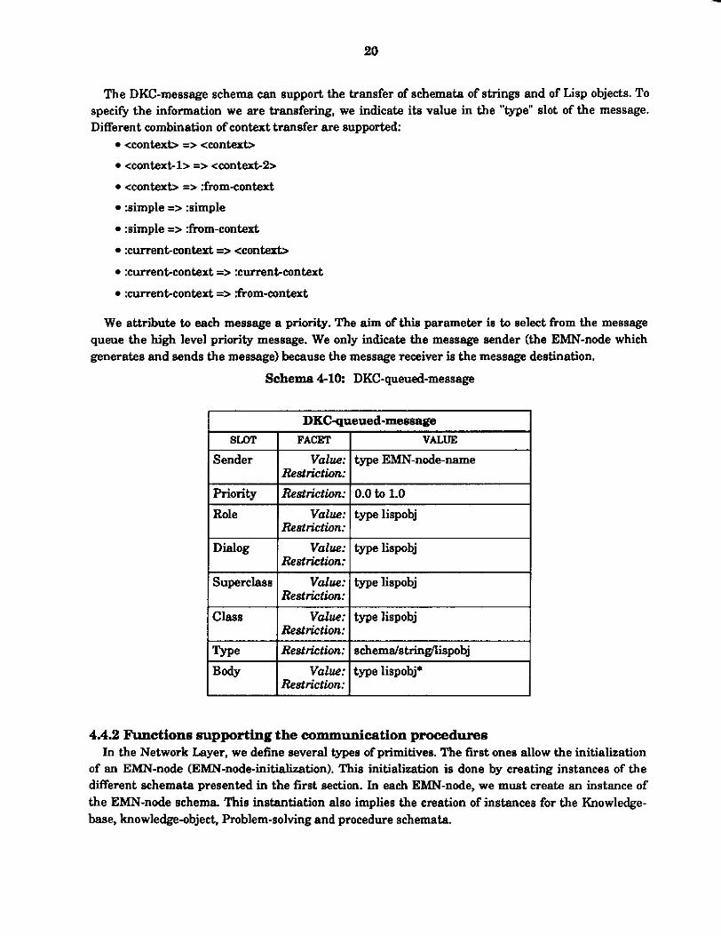
We attribute to each message a priority. The aim of this parameter in to select from the message queue the high level priority message. We only indicate the message sender (the EMN-node which generates and sends the message) because the message receiver is the message destination.
Schema 4-10: DKC-queued-message
Value: type EMN-node-name
DECqueued-messape SLOT I FACET I VALUE I
Superclass Value: type lispobj Restriction:
priority I Restrictiox I 0.0 to 1.0
Restriction:
Class 1 Value: I type lispobj 1 Rest riction:
Restriction: Body
4.4.2 Functions supporting the communication procedures In the Network Layer, we define several types of primitives. The first ones allow the initialization
of an EMN-node (EMN-node-initialization). This initialization is done by creating instances of the different schemata presented in the first section. In each EMN-node, we must create an instance of the EMN-node schema This instantiation also implies the creation of instances for the Knowledge- base, knowledge-object, Problem-solving and procedure schemata.

21
For mutual recognition between EMN-nodes, instances of the channel schema are defined. This defmition is also supported by primitives (link-between-agent-creation).
In addition, we define primitives for communication purposes. The two main primitives are message passing and message reception. We can summarize the communication and synchronization functions we define at the Network Layer:
Message sending * Meaaage-sendmg-with-blocking This function allows the execution of message
passing that blocks the running of the problem solving subsystem until the reception of the answer to this message. The implementation of such a function is specific to each EMN-node. For this reason we will provide a generic and also a specific blocking function. The generic one will execute the Problem Solver blocking without conditions. The specific one will use the generic one and will add conditions for blocking.
* Message-~nding-without-blocking: This function allows simple message passing. It takes place only for asynchronous message passing. In this ease, once message sending is done, the Problem-solving subsystem continues ita processing (implemented as the "&-write" and the "dkc-send" functions).
Message reception * M~age-reception-with-blocking: This function allows message reception with blocking of the problem solving of the EMN-node. For this one we also define a generic and a ~pec i f i~ function. We can establish priority according to the nature of the information which is received.
Message-reception-without-blocking: This function allows simple message reception. In this case, no blocking of the problem solving is executed. Mail box checking is performed once the problem solving has finished ita activity (implemented as the "dkc-read" function).
*Blocking: This is a mechanism for stopping the problem solving subsystem from running. This function is a primitive used by the four other functions defined previously. This primitive causes a selective interruption of the problem solving process out, keeps running two others: message-sending and mesaage-reception (implemented as the "block-EMN-node" function).
*Unblocking: This is a mechanism to re-start the running of the problem solving subsystem. It is also a primitive function used by the previous ones. The utilization of this function can only take place after the utilization of the blocking one (implemented as the "unblock---node" function).
4.4.3 Example of communication function implementation
communication functions. This example assumes the utilization of Va~-3200~~, DECnetn, operating system and Knowledge Craft".
In this section, we defme the algorithms used for a specific implementation of the Network Layer

4.4.3.1 Message passing without blacking Message passing is used to transfer a network-message schema from one EMN-node to another
(taking into account protections). This transfer is done using the channel schema and also the mail box and semaphore box of the EMN-node destination of the message. The different steps of this primitive are described in f w r e 4-1.
I(dkc-send-message 1ow-level-message-name)l
error message
lock-channel creation of a semwhore-box
1 write-message
into mail box
1 semaphore-box
Figure 4-1: Message passing algorithm
The message passing function includes several steps (figure 41). The first one concerns the identification of the message destination. Through the creation of channels, each EMN-node has knowledge about the existing EMN-nodes of the global system. A message can be sent from one EMN-node to another only if the corresponding channel already exists. Once the channel existence verification is performed, we a n test the availability of this channel. The aim of this test is to prevent wnflict6, i.e. if t w o EMN-nodes want to write in the same mail box a t the same time.
This second step is the verification of the channel (and also mail-box) status. When the mail box file already exists, we verify the existence of the semaphore box. When the semaphore box exists, i.e., another EMN-node is reading or writing into the mail-box, the EMN-node waits until it is deleted. The semaphore box is llsad to lock both writing and reading of the mail box. When the semaphore box is deleted, we can execute the last step of the message passing primitive, which is a sequence of three phases:

23
1. lock the channel (by creating a semaphore box) 2. write the message into the destination mail box (if the mail box already exists, we
append the new message to this file, if not, we create this file and copy this new message in this file)
3. unlock the channel (by deleting the semaphore box)
The different steps of the message passing function are d e s m i d on figure 4-2 which gives an example with two EMN-nodes.
(AGENT-1 \ rnail-box-2 ? sern-box-2 '? 2 message-1
AGENT-2 0 AGENT-2 0
3
AGENT-1
4 0 Figure 4-2 Message passing steps

4.4.3.2 Measage reception In the Network Layer, a second function is defmed massage-reception (figure 43). This
function allows reading the contente of the mail box. When it is triggered, it checks first the mail box status. When the mail box exists, it means another EMN-node has written a message in it, in which case we verify the existence of the semaphore box. If the semaphore box exists, i.e., the mail box is locked, the EMN-node waita until it is unlocked, i.e. the semaphore box is deleted. When the mail box is unlocked, the second step can be executed.
(check-message) I
L
a semaphore-box
from mail box
deletion of the semaphore-box
Figure 4-3: Checking mail box algorithm
The second step of this function is performed in three phases: 1. lock mail box (by creating 5 semaphore box) 2. read mail box (by copying this message from the mail box t o the EMN-node problem
solving sub-system). Once the message is transfered, it is deleted from the mail box and if the mail box is empty, it is also deleted, i.e. the mail box file is deleted.
3. unlock mail box (by deleting the semaphore box)
This primitive is equivalent to the message passing one except that it reads instead of writing into the mail box and the "mail box existence checking" test is added The mail box existence checking test allows to suppress or to keep the execution of the second semnd step of that function, i.e. before reading the mail box we test if this mail box exists or not, if it does not exists, this function return 'nil. If it exists, the second step is executed, i.e. mail box reading.
The different steps of the message reception function are described on figure 4-4 which gives an example with two EMN-nodes.

25
AGENT-1 2O AGENT-1
3 0
AG ENT-1
4 0
message- 1
mail-box-2 ?
mal I- box-2 message- 1 sern-box-2 ?
M mail-box-2
AGENT-2 0 message-l
Figure 4 4 Message reception steps
4.4.35 Message passing with blocking The last function provided at the Network Layer is blocking. This function allows interruption of
the Problem Solving execution. This interruption OCCUTS when the PS needs information; we suspend its running until the reception ofthe needed information.
The blocking primitive can be used either with message passing or message reception. We describe an example of message passing with blocking, and the reception of the answer, which unblocks the Em-node. In the first steps (figure 4-51, the searcher, due to an information lack during the execution of the Problem Solving, generates a message to aquire this information. Problem Solving is blocked to suspend its running until the reception of the needed information.

1
2
3
4
Phases: AGENT-1 0
(AGENT-1 \ I P.S. blocked I
26
mil-box-2 ? sembox-2 ?
AG ENT-2 0 J
P.S. blocked
Figure 4-5: Message passing with blocking: step I
These first steps consist in the passing of message-1 from agent-1 to agent-2: The problem solving of agent1 is blocked when message-1 is generated.
The searcher verifies the existence of a channel with agent-2 and also the existence of agentZ's mail-box and semaphore-box. In this case, both files, i.e. semaphore and mail box files, did not exist, so they are created by the searcher of agentl. Message-1 is sent through the channel to the mail
Once message-1 is copied into the mail box of agent-2, the semaphore box of agent-2 is
box of agent-2.
deleted, i.e., mail-box-2 is unlocked.
In the second step (figure 4-13), agent-2 receives message-1 (generated by agent-1 due to an information lack). In response to message-1, the responder of agent-2 generates message-2.
This next step consists in mail-box-2 checking by the responder of agent-2. This mail box checking is executed according to these steps:
The responder of agent-2 is triggered by the existence of mail-box-2 file. It checks the existence of semaphore-box-2, Le., the status of mail-box-2.
To lock mail-box-2, agent-2 responder creates sem-box-2 file.
Then it reads the content of mail-box-2.
Once all the messages contained in mail-box-2 are copied to agent-2, mail-box-2 and sem-boxd are deleted.

27
Phases:
P.S. blocked rnail-box-2 ?
sem-box-2 ? mail-box-2
P.S. blocked mall-box-2
AGENT-2
message- 1 0 P.S. blocked
Figure 4 4 Message passing with blocking: step 2
The message generated by agent-2 is sent back to agenbl using the same sequence as in step one (figure 4-7). Step 3 is the passing of message-2 from agent-2 to agent-I.
Phases:
P.S. blocked
P.S. blocked sernbox-I ? 9
10
P.S. blocked mall-box-1
Figure 4-7: Message passing with blocking: step 3

Step 3 contains the following phases: The searcher of agent-2 verifies the existence of a channel with agent-1 and also the existence of agent-1’s mail-box and semaphore-box. In this case, both files, i.e. semaphore and mail box files, did not exist, so they are created by the searcher of agent-2. Message-2 is sent through the channel to the mail
Once message2 is copied into the mail box of agentl , the semaphore box of agent-1 is
box of agent-1.
deleted, Le., mail-box-1 is unlocked.
Phases:
P.S. blocked
P.S. blocked mal I-box-1
AGENT-1 P.S. blocked 14
AGENT-1
l5 0 AGENT-2 0 AGENT-2 0
Figure 4-8: Message passing with blocking: step 4
The last step (figure 4 4 , illustrates the reception of message-2 by agent-1. When mail-box-1 checking is executed and when message2 is copied from the mail box to the KBS, problem solving is unblocked. We must specify that the unblocking takes place only if the message contains the needed information. The following steps are executed:
The responder of agent-1 is triggered by the existence of mail-box-1 file. It checks the existence of semaphore-box-1, i.e., the status of mail-box-1.
To lock mail-box-1, agent-1 responder creates sem-box-1 file.
Then it reads the content of mail-box-1. Once all the messages contained by mail-box-1 are copied into agent-1, mail-box-1 a n d
*As message-2 contains the needed information, this information is provided to the
sem-box-1 are deleted.
Problem Solver and the PS is unblocked,

29
4.5 Network Layer example
layer to this empty structure, we get figure 4-9. If we continue to describe the example we used in section 2 ( f w e 3-4), by adding the network
The main modifications which occur in this structure are: The initialization of the EMN-node. This includes the definition, for each EMN-node, of the decentralized system, of a name and of an address.
The creation of links between the EMN-nodes through the utilization of channels. These channels also include the basic primitives for the message passing activity and all the schemata needed by this activity: queues and network-message schemata.
This first layer provides the frame for communication. Each EMN-node is defined and knows about each others in terms of existence. Basic communication functions are provided to support message exchanges between identified EMN-nodes. In addition, security mechanisms such as EMN- node blocking and unblocking are specified.
NETWORK
CHANNEL
Figure 4-9 Network Layer implementation example

30
ANSWER
5. Data Layer
5.1 Introduction Assuming the existence of the Network Layer, we define the Data layer of the manufacturing
architecture aa the step for the d e f ~ t i o n of the objects supporting intelligent communication between EMN-nodes.
A decentralized structure, to be coherent, must exchange information between its different EMN- nodes. For that p-e, messages are sent through the network between the EMN-nodes.
The Data Layer provides EMN-nodes with the capability to explicitly request and send information, in the form of schemata, f rodto other EMN-nodes. The protocol for requesting and asserting information between EMN-nodes is based on a subset of SQL [6,281. In this version, schemata correspond to tables, and slots correspond to fields. Protection is provided at the schema level; access to schemata may be locked and the requesting EMN-node blocked until the schema is unlocked.
d QUERY
Figure 5-1: Query elements
The Data Layer contains the basic schemata manipulated and the language to express queries for objects belonging to the KBS. These elements am a set of schemata allowing the manipulation of high level information and the definition of a query language used to express an EMN-node request for a specific piece of information in structured way. These requests are defined for XBS objects.
The information flow between EMN-nodes is dependant m each of their needs. These exchanges are carried out to satisfy a request for information not available in the Knowledge Base subsystem of an EMN-node. The request is done at first on a specific typ of information (using for example the CRL command GET-VALUE"). These exchanges can also be performed for the purpose of
'%'or exrunple, in the e u m t CRL (GET-VALUE ?dochim 'Capacity) in thi. came "machine" is the sebemp name and "capacity" is the slot name. U this vdue is available in the h w l + Base subsystem. it is returned; if not, M ermr meaaage is raturned.

31
consistency. We will see at the next Layer that several kinds of communication processes can be defined. At. this Layer we must provide all the elements to support these communication types.
T w o sets of elements must be defined (Figure 5-lk The schemata manipulated (objects),
The query language.
The query language allows the expression of a need for information in a generic and understandable way. The objeds provide the frame for the information definition and also for the information exchange. Both must take into account several types of communication capabilities and must be compatible (because the query language manipulates the objects and the result of a query is an object).
We have identified four type of objects: Information: is a reference to the knowledge base. Each information object is represented as a schema or part of a schema (slot).
-Message: is defined as a combination of an information need, a producer and a destination. Each message is an instance ofthe generic message schema
Answer: is generated to answer a specific message schema The answer schema includes all the slots of the message d e m a with, in addition, a statu8 slot (which indicates if the information request is provided or not) and the schema-name-answer slot (whose value is nil or the needed information).
Communicafion schema: is the schema which provides the capability of the Enterprise Management Network to efficiently acquire and distribute the information. Through the utilization of a dictionary (and of a communication language), each EMN-node has the capability for mutual understanding. The correspondance table allows an efficient information search by defming the owner of the used schemata. The User-table defines the users of the schemata owned by a specific =-node.
In the rest of this section we describe these two aspeds, objects and language. In addition, we introduce the communication information consistency primitives which maintain coherence between the different tables and schemata used for the communication activity between the EMN-nodes. These tables are defined as slots of the communication schema and are presented in the next section.
6.2 Schemata manipulated Each EMN-node is an agent of a distriiuted system. Thir means each EMN-node has to perform
specific activities which represent a part of the global activity ofthe whole system. Each EMN-node has the capacity to perform its own activity, but there are some limitations in terms of bounded rationality, consistency and coordination. Ifa system is composed of n EMN-nodes, the realization of n taaks (one by each EMN-node) is not enough to ensure consistency for the global result. Consistency can only be achieved through negotiation and cooperation. Besides, bounded rationality implies distribution of the knowledge in each EMN-node with some restriction on their completeness. All these facts produce a need for a communication activity between the EMN-nodes.
In the Network Layer, we have defined the primitives for a message passing functionality. In this level we are going to use these capabilities by building upon them the frame for more intelligent communication, allowing information search, cooperation, negotiation and coordination.

To communicate means that each EMN-node can exchange information with all the others. Each EMN-node can receive or send messages according to its needs and also according to the requests it receives. We can define what these possible exchanges are. We indicate in figure 5-2 the different transactions which can occur in an EMN-node.
We indicate in this figure two kind of transactions: the request and answer for information and the updating activity.
b io send
answer answer
Figure. 5% Object flow representation
To support these exchanges, an EMN-node manipulates four types of schemata: information (or schema),
message,
answer and
the communication schema.
5.2.1 The information schema An information object is a reference to the knowledge base (schema 5-1). It can be an entity or
an attribute of an entity. In our case, we mnsider an information object to be schema, because the elements of the Knowledge Base subsystem are schemata. The problem solving subsystem asks for the value of some d o t of some schema These values are either available or not in ib Knowledge Base subsystem. If they are not available, this means that either the schema or the slot (or both) are not present in the Knowledge Base subsystem. In this ease, the E"-node must get the schema from another EMN-node. To get this schema, the searcher generates one (or several) message(s). The responders of the other EMN-nodes generate answers to provide the requested schema to this EMN- node. "Answer" and "message" are schemata The information object are manipulated by the central kernel. The Knowledge Base subsystem provides them (if they are available) and the problem solving subsystem uses them.

schema 5-1: Information
Information SLOT I FACET I VALUE I Value: typestring I Name Restriction: I
I E c o n I Restriction: I tvpe schema-namdslot-name I I ~oek-status I Restriction: I trnil I I Shared-statu I Restriction: I trnil I
In our definition of what is an information object, we have kept the capability to express it either as a schema or as a slot of a schema. In addition, we introduce the conceptn of locked information and shared information. The first aspect concerns the protection of information. The second concerns the behavior of information.
The locking of an information can be used when conflicts appear. An example can be: two EMN-nodes want to read and update the same information at the same time. In such a case, a priority is de6ned between the two EMN-nodes and in between the information is locked. This mechanism prvvides security in term of information consistency. The concept of shared information is defined an follow: an information is said to be shared when it has several owners, i.e., several EMN-nodes allowed to update the information globally along the decentralized system. This concept defines the nature of an information.
5.2.2 The message schema A message object is an information + a destination + a producer (schema 5-2). We have several
kind of messages: we have the messages sent due to a request for information coming from the central kernel or we can have updating messages sent because of a Knowledge Base modification. We have created a schema called message to be used by the communication system. This schema is generic. The communication modules, to use it, generate instances of the message schema. For each instance of the message schema, we must fill all the slots. Since a message schema is created due to an information need, an information distribution or an updating activity, we use the name of that information which is either needed or updated or distributed. This information is always a schema.
The first slot, number, is a label wed to identify the message. In this way we will be able to make the correspondance between an answer and its corresponding message. This label will be used to check if the information request has been resolved or not.
The type slot can have four values: info-search, update, distribute-END, distribute-LC or distribute-UT. In this way, we make the distinction between an updating message, a distribution activity and a message created due to an information need. According to the type, the responder which receives a message will generate an answer (if it is the info-search type) or will update its Knowledge Base subsystem (ifit is the update type) or will trigger ita own distribution process (if it is the distribute-CT or distributeLC type). The distribute-END message type concerns the deletion of an EMN-node in the global system.

The priority slot is filled with a number (0.0 to 1.0). We currently use two values: 0.5 for the search-info message type and 1 for the update message type. But this slot is allowed to receive all kinds of values. This slot will be used when a responder has several messages in its mail box. These messages will be processed according to their priority.
Schema 5-2: Message
The schema-name slot is the name of the Bchema needed by an application and not available in its Knowledge Base subsystem (for example the schema “machine”).
The slotname slot is the one needed by an application. We indicate this slot-name just to be sure that the EMN-node which will provide the answer (this means the schema) will include that slot (for example the slot “capacity” of the schema machine).
The schema-name-translated slot is the translation of the schema-name into the communication language. As we have seen, each EMN-node ha5 its own internal vocabulary. These vocabularies are different from one EMN-node to another. To solve this problem, and to allow communication, we must use a generic communication language understandable by all the EMN- nodes. When the searcher generates a message to get a schema, the needed schema name is translated into the communication language (to be understood by the responder of the EMN-node which will receive the message). The responder which receives the message translates the needed schema name from the communication language to its internal EMN-node vocabulary.

55
SLOT
The dot-name-translated slot is the translation of the slot-name into the communication 1anguagel6.
The producer slot is the local address of the message sender.
The deetination slot is the destination of the message.
Each time an information object (a schema) is needed by the problem solving subsystem of an EMN-node and not available in its Knowledge Base subsystem, the searcher generates an instance of the message schema. For the updating message it is the same thing. The main problem for this instantiation is to determine the destination and the translation of the slot and schema requested or updated. These slots are completed by the searcher, which determines their values according to heuristic rules and a dictionary. Regarding the distribution activity, it can be triggered for different reasons. The first one is at each EMN-node initialization. The second is at the reception of distribution messages from another EMN-node. The last possibility is for the creation of new schemata.
Schema 63: Information-search-message
~~
FACET VALUE I Information-search--me -7
Instance Number
Type M O T i t Y
Schema-name Slot name
Restriction: message
Restrictiox infwsearch Restriction: 0.5
Value: 1
Vdue: machine-1 value: capacity
Destination
For information search activity, we add the slot slot-name, to be sure that the EMN-node which will provide the answer, will include in it the gwd schema but also the complete schema (with the needed slot) (we give an example of an information search message schema 6-3). For this type of message, we w e the translator function to translate the information need (schema-name slot-name) expressed with the internal --node vocabulary into the generic communication language (schema-name-translated slot-name-translated1 understandable by the other EMN-nodes.
'%e mmmuDication language we have dehed io CUT specific implementation jwt rvpprts direct translntion of one "word' into mother unique "word'. " M a k h d ortranslation is in rmst canes not emu&. Tbe kmwkdge remnfjgurption aspect ia n& taken into somunt. In OYI next implementation we rill rmdik thia atrvchva by devebping a more wpbistiepted system allomng US to mpport a specific mmmunieation language dediented to the natura of the &.tination EMN-node. We sperify these fundionalities in the puey language we d d e in the next pert

S6
Schema 6 4 Updating-message
Number
Type Prioritv
Upda ting-message SLOT I FACET I VALUE
Value: 2 Restriction: update Restriction: 1
I Instance I Restriction: I messaee
Schema-name Schema-name-translated Schema-name-updated
Producer
Value: machine2 Value: machine-2-translated Value: (machine-2-translated
(ATTRIBUTE (capacity-translated lOO-p/h)
(RELATION (is-a machine))) (type-translated drilling-machine))
Value: EMN-node-1 I Destination I Value: I EMN-node-2
For updating messages, we add another slot schema-name-updated. This slot contains the schema, with its slots and values, which is to be updated in the other EMN-nodes (we give an example of an updating message schema 5-4). In this kind of message, the translator function is used for the two slots: schema-name-translated and schema-name-updated. We must translate the value of these slots into the generic communication language because this information must be used by other EMN-nodes having not necessarily the same internal vocabulary.
Schema 5 - 6 LC-distribution-message
LC-distribution-message SLOT I FACET I VALUE
I Instance I Restriction: I message I Val&?: 1- Restriction:
3
distri i te-IC R i O r i t y Restricth: Local-channel Value:
Value: Destination Value:
1 Oocal-channel-1 (RELATION (instance DKC-channel)) (AlTRIBUTE (mbox-name mbl)
(semaphore-name seml) (node EMN-node-1) (key-words kwl kw2 kw3)))
EMN-node-1 EIUN-node-2

57
SLOT
Instance Number
Type Priority UT
For distribution activity, according to its nature, we add a specific slot. If we distribute the local- channel schema, the message type will be "distribute-LC and the message created will contain a slot called localchannel having as value the loeal-ehannel sehema (we give an example of a local- channel distribution message schema 5-5. In this example, EMN-node-1 provides its local channel schema to EMN-node-2.).
scbema 6-6: UT-distribution-message
FACET VALUE
Restriction: message value: 4
Re8trictwn: distribute-UT Restriction: 1
Value: ((article-1-translated (EMN-node-2 EMN-node31
(EMN-node-2 EMN-node-4)) (article-2-translated
I Producer I Value: I EMN-node-1 Destination I Value: I EMN-node-2
For the distribution of local channels, no use is done of the generic communication language. Because, the information distributed concerns mainly file addreases which have unique names. If we distribute the user-table, which is defined as a slot of the communication schema, the message type will be "distriiute-UT" and it will contain a slot d l e d Ul' having value the user-table (we give an example of a user-table distribution message schema 6-6. In this example, EMN-node-1 sends this distribution message to EMN-node-2). The distribution of the UT needs the utilization of the translator and of the generic communication language for the same reason as for the updating activity.
Schema 5-7: distribution-END-message
distribution-=-message SLOT I FACET I VALUE I
I Instance I Restriction: I message I
lTvpe I Restriction: I distribute-m I I Priority I Restriction: I 1 I 1 Producer I Value: I EMN-node-1 1 Destination 1 Value: I EMN-node-2 1
The distribute-END messages type are generated when an EMN-node is removed from the global system. In such a case, it informs the other EMN-nodes about ita deletion. This message type
contains only the EMN-node name to be deleted. The EMN-nodes can accordingly remove the channel and the value of this EMN-node from all the tables it is member (we give an example of a distribute-END message type in figure 6-7. In this example, EMN-node-1 is removed from the global system and informs EMN-node-2 of this deletion).
Number
status Schema-name-translated
Slot-name- translated
Schema-nam+answer
Producer
Destination
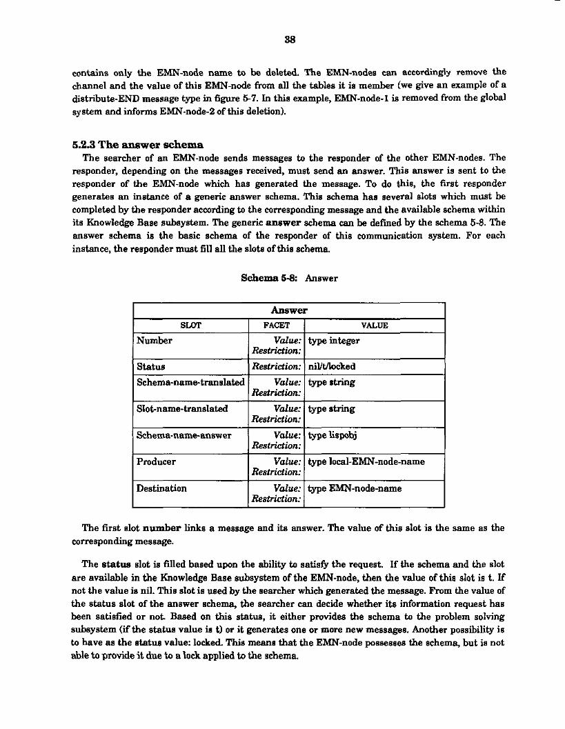
5.2.3 The anewer schema The searcher of an EMN-node sends messages to the responder of the other EMN-nodes. The
responder, depending on the messages received, must send an answer, "his answer is sent to the responder of the EMN-node which has generated the message. To do this, the first responder generates an instance of a generic answer schema. This schema haa several slots which must be completed by the responder according to the corresponding message and the available schema within its Knowledge Base subsystem. The generic answer schema can be defined by the schema 5-8. The answer schema is the basic schema of the responder of this communication system. For each instance, the responder must fill all the slots of this schema
Value: typeinteger Restriction: Restriction: nil/tAocked
Value: typestring Restriction:
Value: typestring Restriction:
Value: typelispobj Restriction:
Value: type local-EMN-node-name Restriction:
Value: type EMN-node-name Restriction:
Schema6-8: Answer
The first slot number l i n k s a message and its answer. The value of this slot is the same as the corresponding message.
The status slot is filled based upon the ability to satisfl the request. If the schema and the slot are available in the Knowledge Base subsystem of the EMN-node, then the value of this slot is t. If not the value is nil. This slot is used by the searcher which generated the message. From the value of the status slot of the answer schema, the searcher can decide whether its information request has been satisfied or not. Based on this statue, it either provides the schema to the problem solving subsystem (if the status value is t) or it generates one or more new messages. Another possibility is to have as the s t a t u value: locked. This means that the EMN-node possesses the schema, but is not able to provide it due to a lock applied to the schema.

39
Instance Number status Schema-name- translated
The schema-name-translated slot is directly derived from the Bame slot of the corresponding message schema.
The slot-name-trmelated slot is also directly derived from the same slot of the corresponding message schema.
The main slot of the answer schema is the schema-nameanswar. This slot contains the answer: the schema requested or nothing, according to its availability in the Knowledge Base.
The last two slots producer and destination are the reversed values as those of the corresponding message.
Schema 6-9: Answerexample
Restriction: answer Value: 1
Restriction: nil Value: machine-1-translated
Answerexample SLOT I FACET I VALUE
Schema-name-answer Producer Destination
Val&% nil Value: EMN-node-2 Value: EMN-node1
I Slotname-translated I Value: I capacity-translated I
We give in schema 5 9 an example of an instance of the answer schema. This answer is the one generated by the EMN-node2 towards the EMN-node-1 in response to the information-search- message of the figure 53. In that case, the EMN-node-2 does not possess the information (status nil).
5.2.4 The communication schema Each node is independent and autonomous. But to ensure coordination within the global
structure, it is necessary to update all the individual subsystems. The EMN-nodes must exchange messages to get information not available in their own Knowledge Base subsystem (figure 5-31. For this purpose the searchers send messages to the responders of the other EMN-nodes.
The main problem in this activity is knowing the schema needed or modified by the central kernel, to determine the destination of the message. The central kernel provides the schema to acquire or to update to the searcher. The searcher must build an instance of the message schema by defining all the elements of the message. The determination of the destination of the message is the main difficulty of this activity.
The other problem concerns knowledge representation and understanding between the different EMN-nodes of our structure. The vocabulary used to identify a piece of information from one EMN- node to another is different. The information represented in an EMN-node by a single schema,

40
identified by a unique name, can represent, in another EMN-node, a set of schemata. This identification and re-construction of knowledge appears to be one of the main difficulties. To help us in this task and also to provide the capability of a more intelligent communication activity, we defme a communication schema.
essage
answer
Figure 5-3 Decentralized Knowledge Craft running
A communication system includes some generic and some specific parts. The owner address of a schema and the internal vocabulary of an application (EMN-node) are specific. To be able to exchange information between the EMN-nodes of Decentralized Knowledge Craft (DKC), it is necessary for each EMN-node to know where to get its needed information and to understand the messages. For this purpose we have created a schema called the communication schema (schema 5-10).
The first slot, correspondance-table, provides the owner address of the schemata which are used by an EMN-node but not available in ita Knowledge Base subsystem. We assume that each schema has only one owner except for the shared schemata which have several owners. In the m e of shared schemata, we use the "shared-schemata" slot to indicate their list of owners. Each shared- schema has several owners and one main owner. T h e main owner is the only one allowed to send global updating messages to the users of a shared schema The other owners must go through the main owner to send global updating messages. An EMN-node is the main owner of a shared schema when that schema appears both in the User-table slot and shared-schemata slot.

41
User-table
Locked-schemata
Shared-schemata
Updated-schemata
Dictionary
Local-address
The second slot, user-table. is used for the updating activity. The local EMN-node has the responsibility for updating the schemata of which it is the owner. It has the responsibility to transfer the updated schemata to the other users. In t h i s slot, we indicate the schemata owned by the local EMN-node and for each of them we indicate the wers (the other EMN-nodes which use that specific schema).
Schema 6-10: Communication
Vdue: type (information (EMN-nodename [, EMN-node-name, ... I))* Restriction:
Value: type (information (EMN-node-name I, EMN-node-name, ... 1))' Restriction:
Value: type (information (EMN-node-name [, EMN-node-name, ... I))' Restrictiorc
Value: type information* Restriction:
Value: type (information string);
Value: type local-EMN-node-name &St&iOA:
Restriction:
Communication SLOT I FACET I VALUE I Correspondance-table I Value: type (information EMN-node-name)*
&Sf&WA:
The third slot, lockeddemata, indicates the list of inf~rmation'~ object which are locked, i.e. the EMN-nodes cannot access either for read or write. The locking mechanism is applied only to the information object which are shared by two or more EMN-nodes. The regular policy for information updating is the single owner policy, i.e. only one EMN-node is able to globally modify and update a specific piece of information in the entire decentralized system. But, all the EMN-nodes can modify locally the information they use. For shared information, i.e. information object have several owners which are able to globally modify or update them, this policy is modifid each owner can update a shared schema but the global update is done by the main owner, which is unique. This global update can be triggered either by the main owner or by the others, Le., if the main owner modifies a shared schema, it updates it globally; if another owner modifies a shared schema, it sends an updating message to the main owner which executes the global update according to this received updating message. For these special shared schemata, to keep consistency, we use a locking mechanism. We must lock these shared objects when two owner EMN-nodes want to read and modify the same information globally. This slot contains the list of locked schemata and, for each locked schema, the EMN-node name which causes the lock.
lrJn our current impkmentation. we amide? idormstbn objeet to be &mats.

42
Shared-schemata
Updated-schemata
The fourth slot, shared-schemata, indicates the list of information object which have several owners, i.e., several EMN-nodes are able to update globally this information. This slot indicates the list of shared schemata and their owners.
The fifth slot, updated-schemata, indicates the list of information object which has been modified between two updating sequences. Each time an information object is modified by an EMN- node, if the information object is owned by this EMN-node, we add the information object as another value ofthis slot.
The sixth slot, dictionary, establishes a correspondance between the internal vocabulary of an EMN-node and the generic communication language.
The last slot, local-addmas, indicates the address of the local EMN-node.
Schema 6-11: Communication
Value: (article-3 (agent-3))
Value: (article-1 (agent-2 agent-3))
Communication a m I FACET I VALUE
~~
Correspondance-table
User-table
Value:
Val&?: -I (operation-1 agenb3) (operation-2 a g e n t 4 (operation4 agent31 (machine-1 agcmt2) (machiie-8 arrent-2) (article-2 (agent2 agent-3)) (article-3 0) (article-1 ( a g e n t 4 (article-2 (agent-3))
I Locked-schemata I Value: I I
Dictionary I value: I Lmcal-address I value: I 'agent-1
We give an example of a communication schema (schema 5-11). This schema is the one created for the agent-1 EMN-node. It contains the schema owned, shared and used by this EMN-node. In this example, the name of the EMN-node is indicated in the local-address slot: agent-1. This communication schema indicated the schemata owned by this EMN-node. They are indicated in the User-Table slot. Besides, for each owned schema, its list of user is defined. In the Correspondance- Table slot, we indicate the schemata used by EMN-node agent-1. For each schema used by this EMN-node, we define ita owner. The Shared-Schemata slot indicates schemata which are owned by several EMN-nodes (agent-1 is one of these owners). The agent-1 is the main owner of the two schemata which are shared by several EMN-nodes because they also are indicated in ita User-Table. If they were indicated in ita Correspondance-Table, the main owner would have been the EMN-node indicated in this table. All the other slots have no values a t the beginning because they are filled during the EMN-node running and used by the different communication sequences.

43
As we have aeen previously, one of the main difficulties for communication is the determination of the destination of a message.
A message is sent to a destination to get needed information or to update the Knowledge Base subsystems of the other EMN-nodes. The destination is another EMN-node of the decentralized system (DKC). Each message schema has a slot called "destination". This slot indicates where to send the message. For determining this destination, we have several possibilities: direct communication, friend selection or broadcae.ting. In the seareher, when we build a message, we try at first to use direct communication. For this purpose, we use the correspondance-table for information search and the user-table for the updating activity. The correspondance-table ia a slot of the communication schema which gives the owner address of each schema used by an EMN-node (application) and not available in its domain modeling subsystem. The values of this slot are lists (pairs): the first element of a pair indicates the schema name and the second one the address of the schema owner. We must build one correspondance-table per EMN-node. Similarly for the user- table, for each schema owned by the local EMN-node, we indicate the list of users (EMN-node addresses).
Since each EMN-node has its own Knowledge Base subsystem, we have a lot of redundancies between them. In addition, since the utilization of these entities is different, their contents can be different. The vocabulary in each EMN-node ean be different. Because of this, we must have a standard communication language to exchange messages between the EMN-nodes. To use the content of the messages, we must translate them into the local EMN-node language. For this we use a Translator rr) which is a part of the Knowledge Base Manager. So, we have two vocabulary types:
An internal one: uaed by the local central kernel (problem solving subsystem, knowledge base subsystem and knowledge base manager). This vocabulary is specific t o an application (EMN-node).
A communication language: used for communication between the EMN-nodes. It is a standard vocabulary used by the responder and searcher of each EMN-node.
The dictionary (or translator) is another slot of the communication schema. It produces a correspondance between the internal vocabulary of an EMN-node and the communication language. The values of this slot are lists (pairs): the first element of a pair indicates the schema name (using the internal vocabulary of an application) and the second one indicates its translation into the communication language. We must build one dictionary per EMN-node. This dictionary structure is the first step in the design ofthe communication system. This kind of 1-to-1 direct correspondance is not eno& in all cases. For example, a schema in an EMN-node C M correspond to several schemata in another. We need to define a mapping function able to establish the connection between schemata of different EMN-nodes. Such a function must be able to split up or gather schemata according to the specific context of an EMN-node.
This communication schema representa the specific part of the decentralized communication system, which must be determined for each EMN-node. All the values of the slots are dedicated to an EMN-node. We must determine the schemata needed by the EMN-node and define where is it possible to get them. In addition, the dictionary is dedicated to the EM%node according to the information it manipulates and exchanges with the other EMN-nodes. The user list which is the schemata owned by an EMN-node, is also specific.

44
5.3 Information consistency checking primitives
Information Layer. In the previous section, three different tables have been presented: In the Data Layer, schemata are defined to support the different sequences defined in the
the Correspondance Table (CT): a list of pairs. The first element of the pair is the name of a schema used by the EMN-node but owned by another EMN-node. The second element of this pair is the EMN-node name owner ofthat schema.
The User Table (UT): a list of pairs. The first element is a schema name owned by the EMN-node. The second element is a list of EMN-node names which use that schema but are not owner of that schema. The Shared Schemata Table (SST): a list ofpairs. The first element is a schema name. The second element is a list of EMN-node names which own that schema together with the local EMN-node. For the shared schemata, we earlier defined the concept of main owner. To share a schema means that all the owners are able to modify that schema, But only the main owner can send the updating messages to all the userdowners of that schema. The main owner of a shared schema is the EMN-node which has this schema in its User Table. All the other owners of this schema must have it in their Correspondance Table.
These three tables are used for the communication sequences we will defme in the Information Layer. As we can see, there exists some overlap between these tables (for example between the SST and the Cl' or UT). Besides, we will define in the Information Layer some other schemata called the class schemata which also manipulate infomation already included in these tables. These schemata are defined at the Information Layer and used by the distribution sequence. The class schemata define set of schemata with their users completed by key-words. These schemata are owned by the EMN-node. To keep consistency between all these tables and schemata, we define some primitives which allow the completion of one table using another. We also define primitives which check the internal consistency of one table (the repetition and the validity of the infomation contained in the table).
The table consistency checking primitives are the following (these ones allow an consistency checking of a specific table in terms of redundancy and authorized values):
checkCT+onsisteney: checks the consistency of the Correspondance Table (this one is used for information search, it includes a list of schemata and their owner).
check-UT-consistency: cheeks the consistency of the User Table (this one is used for schemata update, it includes a list of schemata owned by an agent and for each schema ita list of users).
checkSST-consistency: checks the consistency of the Shared Schemata Table (this one is used for the update of the shared schemata, it includes the list of shared Bchemata and their owners).
check-class-consistency: cheeks the consistency of the Merent instanms of the class schema (these schemata are used for the distribution sequence, they include key-words, members and users)l*.
ekeck-key-words-consist en^: checks the validity and non redundancy of the values of the key-words slot of each class schema and of each channel schema
class schema in defined in the Informstion Layer.

45
CT (schema-name owner-name) *
J complete-CT-SST
UT key-words: string' members: schema-name-1. .... users: agent- 1 , .....
(schema-name (user-me-1. ...)I' \
? J I wmNete-UT-SST / I
Cofnplete-dass-SST S S T I (schema-name (owner-name-i. ...)I* I
Figure 5-4: Mutual table consistency checking
In addition, mutual consistency and completion checking functions have been defined (figure 5-4). They allow the completion of one table, using the information of another table:
wmplete-clas~UT: completion of class schemata using the User Table. This function is very important regarding to the information distribution at the EMN-node initialization. The class schemata contains the owned schemata of an --node, their users and in addition some key-words attached to each class schema. This function allows to complete or to create new class schemata according to the content of the User Table.
complete-UT-class: completion of the User Table using the clase schemata. This function checks for the coherence between the User Table and the existing class schemata. For each class member, the User Table must have the corresponding schema. In addition, the users of a specific class member must also be defined as usera of that particular schema in the User Table.
complete-elass-SST: completion of the class schemata using the Shared Schemata Table.
complete-UT-SST: completion of the User Table using the Shared Schemata Table.
complete-CTSST: completion of the Correspondance Table using the Shared Schemata Table.
complete-class-key-words: completion of the class schemata members using the key- words concept attached to each EMN-nodes ofthe system.
complete-key-worb: this function allows to complete the key-words slot of the local- channel schema. It uses the values indicated in the key-words slot of the different class schemata owned by each EMN-node.
All these primitives are used in the initialization of the EMN-nodes and then, depending on the modifications which occur either to the communication schema or the class schemata, some of them can be triggered.

46
5.4 Query language In the previous section, we defined the objects manipulated and needed for an intelligent
communication activity. In this part, we defime the language which manipulates these objects to express in a structured and unambiguous way requests for information defined in an EMN-node. TO defme the different query possibilities, we use an SQL-type query language. SQL is a language defined to access a relational data structure. The general level of the language is comparable to that of the relational algebra SQL (Structured Query Language) is more than a query language. It provides not only retrieval h c t i o n s but also a full range. of update operations, and many other facilities [6,281.
In our case, we do not use the complete SQL language to support information queries between EMN-nodes. We must adapt ita s y n t a x to our purpose. The elements manipulated by SQL are tables, rows and columns (fields). We manipulate schemata and slots.
To use SQL, we have established a correspondance between: table -----> schema and field -----> slot.
In this section, we present the basic constructions for a query. More sophisticated queries can be expressed by combining these basic ones. Our presentation starts with the simple request and goes to sophisticated and precise requests. We conclude this part by describing the locking and unlocking mechanisms.
We will use the same example data base all through this text. Consider 3 schemata: the machine schema, the machine-1 schema and the machine-2 schema The relations between these schemata are described in the figure 5-5.
MACHINE
INSTANCE INSTANCE A MACHINE-I MACHINE-2
Figure 5-5: Information flows representation
(I MACHINE INSTAWCE+INV: hachine-1, Wchine-2 IDEMTIPICATION: C?lPA!z1TY: C o r n : I1
(( MACHINE-1 I( MACHINE-2 INSTAWCE: -chine INST-: Machine TYPE: drilling-machine TYPE : milling-machine IDEIPTIFICATION: DMl IDEN!EIFIC&TION: Mbf2 CAPACITY: lOO-p/h CAPACITY: 50-p/h COLOR: red I1 COLOR: red I1

47
5.4.1 Complete Bchema request To express a complete schema request we have to use this command
SELECT * FROM .--name;
The result is a request for the entire schema. "*" replaces all the slot-names of this schema-name. We could replace the "*" with the names of all the slots of the needed schema
Example: Q u a y get the machine-1 schema EksUlt:
SELECT PROM machine-1;
I{ MA--1 INSTANCE: bIachin0 TYPE : dsillinp-machine IDEUTIPICATIOIJ: Dw1 CZSACITY: 100-p/h COLOR: red I1
5.4.2 Simple retrieval If we want a more specific request for a slot or a set of slots, we must use the following syntax:
SELECT slot-name [, slot-- . . . I FROM schema-name;
This function selects one or several slots (the listed ones) in the given schema (schema-name).
Example: Queru: get the capacity ofthe machine-1
SELECT capacity PRDU ma*-1;
Result:
6A.3 Qualified retrieval
this purpose, we can use the WHERE clause. We can improve our selection if, for example, we know one slot value of the needed schema. For
SELECT slot-- [, slot-name] ... FlZOM scha-nrmo WHERE slot-name= 'value;
~
Example: Query: get the capady qf the
SELgCT capacity I( MACHINE-1
Kesult: machine whose type i s drilling-machine
TRCM machine CAPACITY: 100-plh WEERE type = 'dsilling-m~chine; TYPE: drilling-machine 1)

48
In this case the result is just one schema But if, for example, the machine schema had several instances having a type equal to drilling-machine, the result would be a set of schemata.
In the WHERE clause, we can have a condition on either the slot-name or the schema-name. Also, we have no limitation on the number of conditione.
We can add other conditions using the AND term: SELECT slot-name [, slot-name] . . . WHERE condition-1 AND condition-2;
FROM schprm-nam~
~
Example: Quenyger the capacity ofthe Result: machine w h type is drilling-machine and whew the capacity is more than 7Q-p Ih
SELECT capacity I1 MA-1 FROM machine WACITY: 100-p/h W I I E type = 'drillinp-machine TYPE: drilling-rmchine 11 AND capacity > 7O-p/h;
To improve the different conditions applied to both schemata and slots, we can use the comparison and Boolean operators. The WHFXE clauses can be very sophisticated and include a long set of restrictions on the information we need to acquire. The reason for such a detail is to allow the user to get exactly the needed information without redundancy.
WHERE CLAUSE CONDITIONS
Condition Symbol
Equal Greater than Less than Greater than or equal to Less than or equal to Not equal Between Partial equality Equal to one item in a list Negation Logical connedor Logical connector
- - > < >= <= 0
BETWEEN LIKE IN
NOT AND OR

49
The conditions on schemata and slots we can create can use a combination of several of these operators. The created WHERE clause wnditiona can reach all kinds of sophisticated levels.
The operators described so far allow comparison between schemata or slots values. But since knowledge could be described in each EMN-node of a computer Bystem in different ways, we must add operators providing the capability to combine the resulting schemata and slots. For this purpose, we can use first the arithmetical operators.
Addition Subtraction Multiplication Division count Maximum Minimum Average Sum
+ 8
J COUNT
MAX MIN AVG SUM
All these operators are des& in the SQL language. For their definitions refer to [281. These operators only combine values. We need something more sophisticated, which allows us to combine schemata and slots.
This collection of operators allows slots to be combined and acted upon in various ways. The result of such operations are, in effect, new values for slots which are not held in storage within the system, but which c a n be brought forth or created a t MY time. In this way, we C M adapt the values of a slot according to our purposes without changing its real value, jut its units.
Examde: Query: get the capacity qfthe Result: machine whone type is drilling-machine and where the capacity i s more thun 70-plh give fhe capacity in loti h (I lot = 20 parts)
SELECT (capacity/2Q) (I MACHINE-1 FRQM machine CA?ACITY: 5-lot/h WBERg type = 'drilling-machim TYPE: &illing-machine ]] AND capacity > 7Q-pIh;
With the different commands we have already defined, we are able to select a part of a schema: for example to get the capacity of a machine.

50
Querv: get the capacity tiom
SELgcT capacity u MACHINE-1
Result: the machines whose t y p is &iUing-machine
FRO)( machine CAPACITY: 100-p/h type = 'drilling~chine; IXSTAUCE: machine
TYPE: drilling-machine I)
To complete OUT example, we define a new instance of the machine schema: machine-3. I1 MACHINE-3
CAPACITY: BO-p/h COLOR: green IDENTIFIC&TION: CW? INSTAUCE: Machins
drilling-machine )]
The result of the previous command is a schema issued from one unique schema Such a query is not enough if, for example, we intend to get the total available capacity of the drilling-machines. In this case the query will have the following structure:
Query: get the total capacity f k m the machines whose type is drilling-machine
SELECT SUM(capacity) (I MACHINE
Result:
IIuy( machine S~-cIIpAcITY: 180-p/h WHEW typo = 'drill-chine; TypS: drilling-machine )]
The operators manipulate values. Until now, we have just expressed requests for single schemata But one of the problem to be able to support with our query language is to have the capability to manipulate, to modify, to group or disjoin knowledge. We must be able to combine several schemata into one representing the needed information. In SQL, there exisxiats three other kinds of functions which allow such a combination:
the ordering of information,
joining of information,
queries within queries.
5.4.4 Retrieval with ordering The command ORDER BY causes the selection of values in a specific order. This ordering is
defined on the values of a slot-name in one or two directions: ascending (AX) or descending (DESC). SELECT slot-namel, alot-name2 FROM schemm-name wHE&TE 8lOt-nrme3 = "valw" ORDER BY slot-n.ma2 DESC;
The ordering can also be done on the s lob of a schema The result is a re-organization of the order of the slots in one schema. This ordering can also have two directions.

51
SELECT FROM schema-name WHERE slot-pame3 = “value“ ORDERBY a c h e r m - u ~ DESC;
~ ~~ ~
Example: Quev.get the machine schema whose type i s a drilling-machine, where the capacity is mope than 70-p I h in descending order
SELECT I( BRay machine IPHEAE type = ‘drilling-machine AND capacity > lO-p/h ORDER BY machine DESC;
Q u e m get the Mmes of the instances of the machine schema in demnding order
Result:
MACHINE-1 CAPACITY: 100-p/h COLOB: red I D E N T I ~ I C € i T I ~ : DM1 INSTANCE: M a c h i n e TYPE: ailling-chine ))
Re3ult:
SELECT instance+inv I1 MA-
ORDER BY machino DESC; =chine-2, machino-3 1) m machine INSTANCEtINV: machine-1,
We can also use the command GROUP BY for ordering. This command causes instances of a schema to be grouped and the group8 to be considered as a whole. This command should follow the WHERE clause within the SELECT statement, or immmediatsly follow the schema-name if no WHERE clause is specified. The grouping can be done according to all kinds of characteristics (type, color, capacity, etc.).
SELErn COUNT (slot-name) FROM schema-nama WHERE ... GROUPBY . . . . ;
Example: Quewgei machine quantity aesult: pet type whose c o h in red
SELECT capacity COUNT (instance) II MACHINE-1 PRObImachine CAPACITY: 100-p/h w€IERE color= ’Zed COLOR: red GROUP BY type; INSTANCE: blachine
W E : drilling-machine ) I
11 MA-2 CAPACITY: 50-p/h COLOR: zed INSTANCE: Machine TYPE: milling-machine )I

Queru: get the total number of machines whose type is drilling-mmhine
SELECT COIMT (instance) (( MA-
WHFSE type = 'drilling-machine TYPE: drilling-machine 1)
Result:
FR(yI -chine COUNT-INSTAWCE: 2
5.46 Retrieval from more than one schema
several schemata: To demonstrate the mechanism which underlies the join, lets begin with a retrieval involving
SELECX schema--l .slot-namel, schema-name2. slot-name2 FROM sch---l, schema-name2
The result of such a command is the creation of a new schema having 2 slots: slot-name1 and slot-name2. Each one ofthese slots comes from a different schema.
Such a query is incomplete because we need to define the name of the new schema including the two selected slots. In fact, we must store these slots into a schema. So we must complete the previous request by defining where to store the information (in our case in schema-name-3).
SELECT sch---l.slot-nampl, scherm-name2.slot-name2 FROM schema--1, schema-name2 TO scherm-name-3
The reason for such a query is to allow the re-construction and adaptation of knowledge to our purpose. Using such a structure, we can redefme knowledge according to the specific needs of a specific EMN-node.
Example: Q u e join the machine-1 identifkatbn Result: and the machine3 identification in the query schema
SELECT machine-l.identification, (( QUERY
TO query:
machine-2.idantification MLCHINE-1.ID: D l U PROM machine-1, machine-2 MACHINE-2.ID: bBf2 1)
We can also use the command UNION which creates a request for information derived from two schemata.
S E W .... UNIOM SELECT ... The result of such a query is a schema containing all the slots selected from the first schema and
all the slots selected from the second schema In this case we create a schema called UNION.

63
5.4.6 Retrieval involving queries within queriea All equations have a lea side and a right side. A subquery is a full select statement used as the
right-side expression within a WHERE clause. It is "sub-" in that it i B a query which is subordonate to, or inside of, another query:
SELECT slot-n.me1 FROM schema-n-1 WHERE 8 l O t - ~ u d = (SELECT 8lOt-namp3
FROM s c h e m a - n d WHERE 8lOt-n.311d = 'value)
For the first WHERE condition, we can use all the kinds of operators described previously.
In this case, there is a restriction on the utilization of such a structure. We must have coherence between "slobname2 and the "SELECT"' form to satisfy the equality. This means we must have a one-to-one value correspondance.
Example: Query: get the identqiatwn Result: of the existing mnchines
SELECT idantification I[ rncx3.lNE.l m machino IDENTIBICATIW: Dwl 11 MEERE instance+inv IN
(SELECT in8tance+inv [( m-2 FRaM machine) i IDPWTIFICATION: bQ42 1)
I1 MAcx3.lNE-5 IDENTIPICATION: DMZ 11
If one of the comparison operators precedes a subquery, the subquery must return only one value. Ifa comparison operator is used alone and the subquery returns multiple values, the structure of the query will be inadequate. In above example, we used the operator IN to avoid this problem. But IN can only be substituted if we are testing for equality.
If we want to improve the subquery structure by providing a capability for multiple values between the slot-name2 and the select statement, we can use some operators. We c a n use comparison operators with multiple-valued sub queries if we follow the operator with one of the words ANY, SOME or ALL
SELECT . . . W I 3 E M A = Awy (SELECT . . . ) SELECT . . . WHERE A < ALL (SELECT . . .) SELECT . . . WWERE A > SoLdE (SELECT . . .)
Example of retrieval using ANY: SELECT UNIQUE slot-name1 FROM scherm-n-1, schema-nama2 WEWE schema-n-l.slot-name2 = achPrmu.slot-aame2 AND scbama-narrd4.slot-na~1e3 = 'value

54
This is equivalent to: SELECT a1ot-MmB1 FROM s c h m - ~ m ~ l W B E D 6lot-name2 -ANY (SELECT d o t - d
FROM 6 A - n ~ m a 2 WHERE slot-name3 = 'value)
The operators <=ANY, >=ANY, >ANY, <ANY, nokANY are analogously defined.
IN is equivalent to -dNY.
5.4.7 Locking and unlocking mechanism Locking is a mechanism for protecting transactions fmm intederence by other, concurrently
executing transactions, i.e., the presence of one transactim in the system should not cause some other transaction to produce incorrect results.
We have two possibilities: we can lock either a complete schema or speci6c slots of a schema.
Complete locking schema request: LOCK FROM schartu--;
The result is a request for locking the entire schema. "*" replaces all the slot-names of this schema-name. We can replace the "*" by the names of all the slots of the needed schema.
Example: Q u e v lock the muchine-1 schema Result:
- * FROll machine-1;
[( COMMUNICATION-SCHEMA UX~~C&D-SCIXEWLTA: machine-1 11
Simple retrieval:
If we want a more specific locking request on a slot or a set of slots, we must use the following syntax:
LOCK slot-nama [, Slot-MmB . . . 1 F%OM 6ChelBa-nama;
Example: Query: lock the capacity slot of the machine-1
FRDU machine-1; LOCXED-SCIiEWiTA: (Machine-1 capacity) )]
Result:
Locg capacity I[ COMMUNICATION-SCHEMA
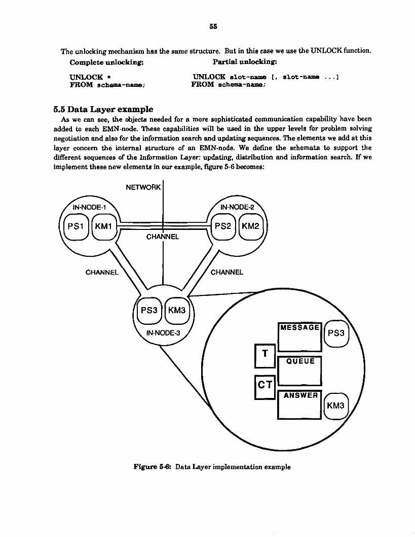
55
The unlocking mechanism has the same structure. But in this case we use the UNLOCKfunction. Complete unlocking: Partial unlocking:
UNLOCK * UNLOCK slot-- [, slot-name . . . I FROM a&---; FROM schema-nama;
6.5 Data Layer example As we can see, the objects needed for a more sophisticated communication capability have been
added to each EMN-node. These capabilities will be used in the upper levels for problem solving negotiation and also for the information search and updating sequences. The elements we add a t this layer concern the internal structure of an EMN-node. We define the schemata to support the different sequences of the Information Layer: updating, distribution and information search. If we implement these new elements in our example, figure 5-6 becomes:
NETWORK I
Figure 58: Data Layer implementation example

6. Information Layer
6.1 Introduction The information layer of the manufaduring architecture provides the functions, rules and
schemata that support information exchange between the decentralized EMN-nodes of the distributed manufacturing system. In particular, the Information Layer supports:
automatic information acquisition and
automatic information management.
The acquisition of information starts from the specific need of a specific EMN-node. Each EMN- node must have the capability to acquire at any moment the schemata used by its Problem solving subsystem but not available in itn Knowledge Base subsystem. It must be able to generate requests, to check messages and to generate answers to s a t i e these needs. We can identie at this level and for this specific purpose two hctionalities:
the message generation (information search) sequence, and
the message and answer reception (answer sequence).
The second function, information management, provides the capability for each EMN-node to maintain the consistency of knowledge throughout the distributed system. We can identify three specific functions:
updating (updating sequence), information distribution, and
communication capability improvement (learning).
The updating activity provides updating of the content ofa Bchema modified by its owner. When the owner of schema modifies it, or when EMN-nodes change a spec& value in a schema they are authorid to modify but don't own (they share), the owner EMN-node can generate an updating message to inform all the users of the schema of the modification. Our policy for the updating activity is one owner per schema, i.e., all the schemata can be read by all EMN-nodes but they can only be modified (gloablly throughout the decentralized system) by one EMN-node: their owner. This rule is true for all the schemata except the ones shared by several EMN-nodes. "Shared means they can be read and modified by several EMN-nodes. But even for these schemata, the updating messages are generated by the unique owner.
Information distriiution is concerned with the creation of new schemata in an EMN-node and the initialization of a new EMN-node in the system. In the first case, the EMN-node will have to inform some other EMN-nodes of the existence of new schemata. The main question is who are these EMN- nodes? Also when and what to distribute? To solve this problem, we defme a user callable function: "diatribution-function". This function identifies, according to the nature of the new schema created, who the "potential" users of this new schema are. To do this, we define a taxonomy of the information and key words attached to each piece of information. The taxonomy will allow the identification of a group of potential users. The key words will permit improvement of this identification. The second use of the distribution function is either a t the initialization of an EMN- node or at the reception of distribution messages from a new EMN-node. The distribution h c t i o n is

67
triggered at the initialization of each EMN-node, to inform the others of ita creation by providing information about its local channel schema, about the schemata it owns (user-table) and about schemata to be updated (class schemata). It is also triggered at the reception of distribution messages from a new EMN-node in the system. The last use ofthe distribution activity concerns the EMN-node deletion. As EMN-nodes generate distriiution messages for their initialization, they also create messages for their deletion. These messages are sent to all the other EMN-nodes to update their tables and channels.
The learning activity uses received messages or information search results, to modify tables (CTRPPISST) defined at the Data Layer and used for communication. The modification of these tables during the running of an EMN-node improves the capabilities of the EMN-node both to acquire the needed information and also to keep information consistent in the distributed KBS.
The EMN-nodes are able to exchange some information according to their specific needs. In this structure, each EMN-node is responsible for a set of schemata or slots depending on the defined policy. Responsible means that the EMN-node is the only one allowed to update the owned schemata or slots. Each piece of informntion has a list of users and one owner. The users are the EMN-nodes which receive the updating messages. We have also seen that for some specific schemata, called the shared schemata, we have a multiowner policy which necemitate the uue ofthe locking mechanism.
For the information search sequence, the policy ia the same. Each EMN-node knows, from the content of the communication schema, who the owner of each piece of information available in the DKC system is. The information search sequence uses this knowledge. In case of failure in the information search other policiea are applied, such as broadcasting.
Each information is used according to specific views and privileges which are defined by the information owner. The objects (schemata or slots) which are created by an EMN-node belong to it. It is the only one allowed to add, remove or change the content of these objects. But an important part of a distributed system is the ability to access information from all EM"-nodes. This cannot be done without any restriction. Some rights must be defined for the accessing capability. The owner of a piece of information must defme for this piece of information who shall be allowed to do what with it.
In this section, we define the access privilege granting policy for the information schema. Then we present in detail the content and the algorithms of the different sequences (updating, information search, distribution and answer) defmed a t the beginning of this section.
6.2 Access privilege granting There are four kinds of privileges: select, insert, delete and update. The giving of these privileges
is called granting. An EMN-node must grant, for any objed which belong to it (owned by it), any of the four privileges to any users (other EMN-nodes) of these objeds. We use the SQL vocabulary from the previous section to define the privileges attached to each schema or slot of a schema.
Each time we want to define the privileges attached to a schema or a slot we must use the word GRANT. This word is followed by one or more of the defined privileges (select, insert, delete and update or all).

GRANT SELECT,INSERT ,... (81Ot-name [, slot-name, . . . I ) ON schema-name TO m-node-name [, EMN-node-name, . . . I ;
Afler the key words, we indicate the slot name on which these privileges are applied (we Can indicate one, several or all the slots ofa schema). If we want to apply the Privileges to all the slots, we put a "*". ARer the "OW key word, we indicate the schema name for which the privileges are defmed. Finally, after the 'TO", we indieate the list of users having these privileges for this schema.
Example: Q u e m grant SELECT and INSERTprivileges for the machine-1 schema to the EMN-Mdes 1 and 2
GRANT SELECT, INSERT (*) ON lnachina-1 TO EWN-node-1, W-nodo-2:
In this ease the privileges are applied to all the slots of the machine schema. If we want to have different privileges for the different slots we have to duplicate this structure.
Query: grant the machine-I achema SELECT and INSERT privileges for the capacity sIot and SELECT for the others to the EMN-nodes I and 2
GRANT SELECT, INSERT (capacity) ou macbino-1 TO Em?-node-1, EMN-node-2;
GRANT SELECT (instance, type, identification, color) ON machine-1 TO EMN-node-1, EMN-node-2;
If we want to add all the privileges for the machine-1 schema to EMN-node-2 for example, we must use the ALL key word:
GRANT ALL (*) ON rmchine-1 TO EMN-node-2;
As we can create privileges, we can remove them. For this purpose we use the REVOKE function. This uses the same structure and key words as the GRANT function. But in this case the privileges are revoked.
REVOKE SELECT,INSERT, - (slot-name I, slot--, . . . I )
FROM --node-name [, =-node-name, .. . I ; ON E&---
In this declaration, we change one key word TO becomes FROM.

69
Example: Query: revoke the SELECTand INSERTprivileges for the machine-1 schema fw the EMN-nodes 1 and 2
W O I C E SELECT, INSERT (*) ON macbina-1 FRCM EW1-noda-1, EMN-node-2:
To complete these elements and the ones described in the previoua section, we ean use other words from SQL for the updating, creation, deletion and modification of the schemata and slots. In each case a specific function is used:
slot value updating UPDATE schema-name SET slotname = neur-value; schema creation: CREATE SCHEMA schema-name ( [slot-name, ... I); slot creation: INSERT INTO schema-name (slot-name L slotname, ... I); value creation: INSERT INTO schema-name (slot-name) VALUES ( value [, value ... I); schema deletion: DEZEI'E schema-name;
slot deletion: DELETE FROM schema-name (slot-name [, slot-name, ... I); For all of these functions, we can use the WHERE clause condition and all the operators defined in
the previous section.
6.3 Automatic information acquisition Automatic acquisition of information provides an EMN-node with the capability to acquire a t any
moment and without knowledge of ita location in the EMN architwture, the schemata needed by ita Roblem solving subsystem but not available in ib knowledge base subsystem. We can identify a t this level two functions:
the message generation (information search) sequence, and the message and answer reception (answer sequence).
Information acquisition occurs automatically, when an EMN-node's problem solver attempts to access information that does not exist in ita knowledge base. Four methods are then used by the knowledge base manager to acquire the information:
1. First, the owner ofthe schema from which the reference to the information was made may be a different EMN-node. Therefore it is reasonable to believe that EMN-node may also have the desired information.
2. Secondly, the schema taxonomy, defined below, contains pointers to those EMN-nodes that maintain schemata of a particular type.
3. Third, the EMN-node maintains a list of EMN-nodes that it comesponds to reguhly and may query them.
4. Fourth, as a last resort the request may be broadcast to all EMN-nodes to which it has channels.

We have defmed in the network layer the locking and the blocking mechanisms. These two primitives provide security and consistency of the information distributed and shared between the =-nodes. Each of the two information acquisition functions can use either the blocking mechanism or the locking mechanism:
The blocking mechanism: During the information search or the information answer, the problem solving activity can be suspended until the end of the search or answer. Blocking is released when the information search or the information answer is finished. The primitive functions for blocking and unblocking have been defined in the network layer. The locking mechanism: The shared schemata, i.e. updated globally by several EMN- nodes, can have their content locked. This m e c h i s m is triggered when an EMN-node able to update a shared schemata wants to read and then modify ita contents. In this w e , we want to prevent information inconsistency, by locking the read schema, (if another EMN-node asks for the same schema, it can get the old version of the schema). The schema lock is released once the read and modifications have been done through an updating message by the first EMN-node requesting the schema. If another request is received by the EMN-node for the same schema during this locking period, answers will be generated with a locked status value. An EMN-node which receives an answer with a locked status value can generate another information search message, repeating until it receive8 the needed schema A schema lock can only be executed during an information- search message reception for a shared schema, and the request must come from one of the owners of the schema The primitive functions for locking and unlocking have been defined in the network layer.
Information acquisition uses these mechanisms in spe&c cases. Blocking is used when an EMN- node needs to synchronize between ita internal problem solving activity and communication. In this case, the blocking function ia triggered when an information search mesaage is generated (to acquire information not available in the local KBS). The unblocking function is triggered by the reception of an answer containjng the needed information. Blockin&nblocking functions perform selective interruption of the problem solving mechanism only, all the other processes (updating, mail box checking and distribution) are continued.
The locking mechanism is triggered by information search messages reception. When an EMN- node receives an information search message which concerni a shared schema and when the agent is the main owner (the schema is member of the UT), the schema is locked The unlocking of this schema is executed at the reception of an updating message for the schema coming from the E"- node producer of the information search message. This mechanism uses the locked-schema slot of the communication system.
Message and answer reception is also an automatic pmcesa. It can be either synchronous or asynchronous depending on the EMN-node implementation and needs (the synchronization of the communication activity and the problem solving activity is performed using the blockinghnblocking functions). Each message (either an updating, distribution or information search message) or answer (in response to an information search message sent previously) is stored in the mail box of the EMN-node. Processes are triggered according to the nature of the messages (the four types enumerated previously).
Periodically, this mail box is checked and its contents evaluated.

61
6.4 Automatic information management
throughout the EMN. We can identify three functions: Automatic infonnation management maintains the consistency of an EMN-node’s knowledge
information updating, information distribution, and
learning communication capabilities.
Information updating maintains wnsistency of schemata in the EMN. When the owner of a schema, or an EMN-node authorized to modify a schema it doesn’t own but shares, makes a modification, the owning EMN-node generates a message to inform the users of the modification. Shared means they can be read and modified by several EMN-nodes, but global update messages are generated by the single owner (called the main owner). The policy defined for the updating activity is a single owner policy. Periodically the owner of a schema generates updating messages and sends them to the users of the schema if it has been modified during the interval of the updating period. This policy is modified for the shared schemata. The owners of a shared schema can all modi6 it and have their modifications known by all the users of the schema. But this updating is always done by the main owner, which receives direct updating messages from the other owners and in reponse to these messages generates the global updating messages. The updating activity uses the updated- schema slot of the communication schema. It contains the schemata modified during the previous updating interval.
The information distribution function sends new schemata to EMN-nodes that are potentially interested. The questions are what, when and to whom should schemata be distributed? To solve this problem, we defined a user-callable function: distniution-function. This function identifies who the “potential” recipients are. Types of information of interest to EMN-nodes are maintained in a taxonomic hierarchy. For each class, a set ofkeywords are used to define the class; that is, schemata that match the keywords are members of the information class. Each class also has a list of EMN- nodes that are interested in the information class. If a recently created schema matches a particular information class, the schema is distributed to the EMN-nodes interested in the class and to any other EMN-nodes interested in d a s ~ ? ~ above it in the hierarchy (subsumed by it).
The other utilization of the information distribution &&on concerns the EMN-node initialization. When a new EMN-node is created in the system, different schemata are created such as the DKC-system, the local channel schema, the queues srbemata, the communication schema and channels with the other EMN-nodes of the global system. To provide each EMN-node enough information about itself, at each i n i t i t i o n . each --node distributes several schemata which characterize their own activity. The first element distributed is the local channel schema It provides other agents with the addresses of ita mail-box, its semaphore-box and also the key-words specific to the new EMN-node. It also distributes ita user-table. The user-table defines the schemata owned by the new EMN-node. The other EMN-nodes are able to complete their own local correspondance-table t h u s improving their information search capabilities. The last information distributed ia the members of the class schemata to the different users of these schemata (the class schemata will be defined in the next section).
When an EMN-node is removed from the network, it informs the other EMN-nodes. It sends distribute-END message types which only contain its name. The other EMN-nodes are then able to delete the channel with this old EMN-node and also they remove this EMN-node from all the tables (UT/Cl'/SST) and class schemata it was member.
When an EMN-node receives distribution messages from a new one, the distribution sequence may be triggered on not. If there is no difference between the DKC-channel schema with this new EMN-node and the local-DKC-channel-schema received in the distribution messages, no distribution is performed. But, if an EMN-node does not have a channel with the new one, the open-channel function is triggered. In addition, the distribution function is triggered to send to the new EMN-node the schemata it can use according to its key-words.
Learning communication capabilities concerns the different tables presented in the Data Layer and used by the different sequences presented previously. It also concerns the class schemata defined for the distribution sequenoe. These functions allow to complete the different tables used for the communication activity according to the performance of the system and also according to the results of this communication.
Four main functions are defined for improving communication capabilities: learn-owner&: depending on the result of a broadcast or updating message reception, the system can complete its Correspondance Table, which def ies schema owners. The Correspondance Table of the Communication schema is completed when a broadcast S U C C ~ ~ S , i.e., the agent receives from another one the information it was lookink for, or when an EMN-node receives an update message for a schema it does not own.
learn-user-&: depending on the information search message5 received by an EMN-node, the system has the capability to complete its User Table, which defines the list of owned schemata and their users. The UT is completed when an EMN-node receives an information search message which concerns a schema owned by that EMN-node.
learn-Bhared-schemata: depending on the remption of updating messages concerning owned schemata, the system can complete the Shared Schemata Table. The SST is completed when an EMN-node receives an updating message for a schemata already owned by that EMN-node.
learn-class-user: depending on the reception of distribution messages from a new EMN- node or from an EMN-node which has created new schemata, the class schemata are completed in terms of members and users using the key-words concept.
6.5 Information Layer example
protocols and functions (figure 6-1) At this level, the main elements which are added to the previous figure 5-6 are the communication

6s
Figure 81: Information Layer implementation example
6.6 Information Layer Implementation The next four sections describe our specific implementation of the information layer into the
communication system of the DKC system. We star t by a description of the information distribution sequence. The distribution activity triggers the other sequences a t initialization. The second sequence presented is the message generation for information search capability. Then, we introduce the updating activity used to keep knowledge consistency in the global system. The last sequence presented is the message and answer reception which either triggers the answer generation functions or the KB update or the distribution sequence or the information search message generation.

6.6.1 Information distribution This activity is triggered by three different events:
At the EMN-node initialization: when a new FAIN-node is created in the decentralized system, it informs the others of its creation by sending information about itself: its user- table, local channel schema and the class schemata members. A t the deletion of an EMN-node: when an EMN-node is removed in the decentralized system, it informs the others of ita deletion by sending messages about it. At the reception of distribution messages: when an EMN-node receives distribution messages containing a local channel schema of a new EMN-node, according tu the content of this schema, the EMN-node triggers its own local distribution activity to this new FAIN-node.
When a new schema is created in an =-node: this schema must be distributed to possible users. This distribution uses the key-word concept.
The distribution activity wes functions (we defme in the next section) to perform selective distribution of information according to different criteria. We present at first these primitives, then in the next two parts of this paragraph, we defme the distribution sequence process a t an EMN-node initialization and the distribution process at the reception of distribution messages from a new EMN-node.
Schema6-1: CLASS
Key-words Vulue: Restriction:
Users Value: Restriction:
Members Value: Ileatriction:
type string
type F"-node*
type schema-name*

85
In our implementation, we have defined five functions which cover these three aspects: distribute-schema: distributes a schema to all its users according to its class
distribute-schema-hierarchy: distributes a schema and ita superclasses, subclasses and
distribute-agent: sends to a specific agent all the members of the diserent classes this
*distribute-~nt-hierarehy: sends to a specific agent all the schemata and their
*distribute-class: performs a general distribution to all the users (EMN-nodes) of a
membership.
instances to all usem according to its class membership.
agent is a user of.
superclasses, subclasses and instances ofthe different classes this agent is user.
specific class of all the members (schemata) of that specific class.
Destination = first user
A I next, user I
Figure 62: Information distribution sequence
On top of these, we have implemented a generic distribution-function which, according to its parameters, triggers one of the previous functions.

The distribution function uses the schema hierarchy linked either by an INSTANCE relation, an IS-A relation and one or several user defined relations. The user defmed realtion are specific to each EMN-node and the ones which have to be taken into account to build the hierarchy of schemata are indicated as a value of the *relation-name* variable. If we distribute a schema, the complete tree under this schema will also be distributed and the direct hierarchy of schemata above will also be distributed (figure 6-3).
In the example presented in figure 6-3, we distribute a schema (which is indicated in black) which has IS-A, INSTANCE, IS-A+INV and INSTANCE+W with other schemata. In this case the distribution of that schema will also imply the distribution of the 2 schemata above it and of the 11 schemata under it.
Schema to be distributed \ \ ~ IS-AwlNSTANcE
link
1 1 Hierarchy of schamala distributed
Figure 6-3: Hierarchical distribution example
The purpose of the distribution in the Enterprise Management Network is very important mainly in te rms of information consistency and acquisition. The role of the distribution function can be divided in two different steps:
Information distribution at the EMN-node initialization or at the EMN-node deletion Information distribution at the reception of other EMN-node initialization messages.
Information distribution at an EMN-node initialization (figure 6-4) consists in distributing the information owned by the EMN-node to the usem. In addition, User-table, Correspondance-table and local-channel are distributed. At the information Layer, initialization triggers the different sequences supported by this layer:
message generation,
message and answer reception, updating activity and
distribution.
The first sequence triggered is distribution. It distributes the Bchemata owned by the EMN-node

67
‘trlggorlng-time. This number can be modifi9d
Using the Other process
executed channels slot d the DKGsystem
This list indicates Ihe define-iist-offch annals
7 kmmr IN-nodes I Dctrbution destination - I first channel
creates distribution-message
mtaining a copy of the bcal channel schema and of the kxal
Send-message-fn USW-Tabk,
Destination = next channel
L m Generates wdatina m e S S a g e s f o r a l l i m ~ ~ a t a
membm of each d a m s lowanis ailthe I N - d e s uylrs ofthese schemala
distiibtile ell cbsses
t Triggers the updating
adivily and the mail tox
Figure 6 4 Distribution sequence for an EMN-node initialization
to all the others EMN-nodes. The schemata distributed is determined by the different classes of schemata defmed in each EMN-node, according to the list of schemata owned by each EMN-node (this list is specific as a value of the User-Table dot of the communication schema) (each EMN-node is responsible for distributing the schemata they own) and in correspondance with the keywords of the other EMN-nodes (the ones recognize by each EMN-nodes, i.e., supported by a channel schema). Schemata are selected by matching the key-words of each class with the key-words of each other EMN-nodes. In addition to the class schemata members distribution, each EMN-node sends to the other recognized EMN-nodes, Le., supported by a channel schema, a copy of ita local channel schema and of its local User-Table. Consequently, each EMN-node receives the key-words attached to all the others (they c a n complete their class schemata members by matching key-words) and, they can complete their local Correspondance-Table knowing the owner of some schemata The aim of this distribution a t the initialization of each EMN-node is to improve the communication capabilities between the EMN-nodes of the system, to ensure. coherence and to provide to each EMN-node

knowledge about the other nodes and knowledges about the schemata they need for their internal problem solving activity.
The distribution of the schemata owned by this new EMN-node is done by using updating message schema. For the distribution of the local channel schema, we use the distribute-E-message schema created by the make-LC-distribution-message. For the distribution of the user-table, the new EMN-node creates a distribute-UT-message created by the make-UT-distriiution-message. In addition, the distribution function triggers according to the modification performed on the different tables and schemata (CTNTISSTlclass) the consistency functions defined at the Data Layer. The triggering of all this activity is supported by a VMS routines. This routine tiggers the distribute-agent-fct which executes the distribution for each known EMN-node (having a channel schema with this new EMN-node) ofthe different information (local-chanel, UT and classes).
To summarize the distriiution activity for an EMN-node initialization, we id en ti^ these steps: 1. The EMN-node to be initialized checks the different channels already created with the
2. The EMN-node sends to each of these known EMN-nodes a copy of its local channel
3. The EMN-node sends to each of these known EMN-nodes a copy of its local User-Table.
4. For each class schema it owns, i t generates an updating message for all the members
For the distribution regarding to EMN-node deletion, the sequences are equivalent. The only difference is in the nature of the information distributed. In this case. we use the distribute-END message type.
other EMN-nodes of the system.
schema.
(schemata) of these different classes towards all their usem (EMN-nodes).
Distribution also ocurs at the reception of distribution messages coming from another EMN-node (figure 6-5). As we have described in the previous paragraph, each EMNmode sends distribution messages (which are in fact updating messages) the other already existing EMN-nodes. At their reception, each EMN-node triggers its own distribution function according to the information received about the new EMN-node. These steps are executed:
1. It checks the existence of a channel schema to this new Em-node. Accordingly, it creates the schema or not and completes the information (using the local channel schema received from that new EMN-node) about this new EMN-node (for example the key-word list attached to this EMN-node).
2. It completes, using the received User-Table of that new EMN-node, its own Correspondance-Table.
3. It creates the schemata sent by this new EMN-node according to its own need (defmed by its local key-words).
4. It completes, using the key words of this new EMN-node, the different class schemata users slot.
5. It triggers the distribution sequence and sends to this new EMN-node its own local channel schema (for information about its key-words) and updating schemata according to the key-words of that new EMN-node matching with the key-words of the class schemata it owns. In addition, it sends its local User-Table.
This sequence is executed between two EMN-nodes until the acquisition by both of them of all the information regarding their keywords. The main test to stop replying to a distribution messages

I distribution-message I
d*tribute all classes members matching with the key-words of this new EMN-nod ~
1
6.6.2 The message generation Bequence
used for this activity, and we develop the contents of these functions in this section. The message generation sequence is presented in figure 6-6. We introduce the different functions
The function make-message-fn is the basic function of the message generation sequence. It is used to generate instances of the message schema: message-1, messaged, ... ,message-n. All the other functions will be used either to trigger or to complete some slots of the message schemata generated by the make-message-fn function.

I (GET-VALUE 'schema-name 'sbt-name) I
trigger
block-agent
I .
Ushg 'Yranshtor-ln" and *address-fn ". Maksmessagkfn
Messagecreated &
Broadcastlng & Destination - Deslination -
Send-messagefn Message sent
Destination - to the owner next agent agent
Figure 6-6: Message generation sequence

71
Restriction: Restriction: Restriction:
The make-message-fn function creates an instance of the message schema. As a message is created according to an information need (which is a schema), the first elements provided are the needed schema name and slot name (because the command GET-VALUE provides them). With these two data, we can fill the two slots "schema-name" and "slotname" of the generated message schema. For the "instance", "priority" and "type" slots, their values are always the same for each message. The value of the slot "number" is filled with an integer. That is incremented each time a new message is created.
For the four other slots, we use the "translator-fn" and "address-fn" functions. The first function translates the schema name and slot name needed fmm the internal vocabulary to the communication language. The second one defmes where to send a message depending on the needed schema. Both of them w e the communication schema,
The triggers of the make-message-function are the three following schemata: no-schema-spec, no-slotspec, no-value-spec. They are triggered when the CRC system creates an error message using the system-error schema.
Before describing these triggers, we define the EMN-node-blocking mechanism. We have defmed a function called Block-EMN-node whose purpose is to suspend the internal problem solving activity of an EMN-node. This function only suspends the process. The other functions, such as mail-box-checking, updating, or distribution, continue. The block-EMN-node function allows the interruption of the internal problem solving activity when information is not available locally and the communication system has to q u i r e it through message sending. In this case, the internal problem solving activity is interrupted until reception of the needed information, and is then re- started using the unblock-EMNmode function.
The unblock-EMN-node function is triggered by the receive-answer sequence. Depending on the content of answer received in response to an information search (with block-EMN-node), we unblock the internal problem solving of the EMN-node. The unblock-EMN-node function is triggered when an answer contains the needed information. In this case and only in this case, the internal problem solving of the EMN-node can continue its processing.
Schema 6-2: NO-SCHEMA-SPEC
error-spec value nil
NO-SCHEMA-SPEC 1
Restriction:
Instance
Signal
(Iambda (X, (when *trace*
(create-schema (get-value x 'schema))) lformat t"-%There is 110 schema by that name and"))
FACET I VALUE

72
Restriction:
The schema no-schema-spec is the first trigger of the make-message-fn function. This schema is an instance of the error-spec schema. It is connected to the "no-schema'' slot of the "system-error" schema. Each time the CRL system fmds a "no-schema" error type, it triggers the "value" slot of the "no-schema-spec" schema. The "value" slot executes the make-message-&.
The "no-schema-spec" does not trigger the make-message-fn because if we have a no-schema error, we also have a no-slot error. Therefore we have given the trigger responsibility to the next schema: no-slot-spec.
Schema SS: NO-SLOTSPEC
(lambda (r) (when *trace*
(format t"-%There u no slot by thui nume.'?) (make-messoge-fn @et-value x '&ma)
(get-value x 'slot)) (send-message-fn @et-value 'mesaage 'instance+inu)) (create-slot (get-value x 'schema) (get-value x 'slot)))
I NOSLOT-SPEC
Value
FACET I VALUE
Restriction: I error-sDec Restriction: I value Restriction: I nil
"he schema no-slot-qec is the second trigger of the make-message-fn function. This schema is also an instance of the error-spec schema. This one is connected to the "ncdot" slot ofthe "system- error" schema. Each time the CRL system fmds a "no-slot" error type, it triggers the "value" slot of the "no-slobspec" schema. The "value" slot triggers the make-message-& function.
The no-slot error type can be generated in two eases: if there is no schema (so there ia also no slot) or if there is no slot (but the schema exists). Once a message is created, we must send it to its destination (which is indicated by the destination slot of the message). For this purpose we use the send-message-fn function.
The last trigger of the make-message-fn function is the no.value9pec schema. This schema is also an instance ofthe error-spec schema. This one is connected to the "no-value'' slot of the "system- error" schema. Each time the CRL system finds a "no-value" error type, it triggers the "value" slot of the "no-value-spec" schema. The "value" slot executes the make-message-fn.
Once an instance of the message schema is generated, we must send it to another EMN-node to get the information (schema). The purpose of the send-message-fn is to send the messages. We have several possibilities for the destination of a message: if the destination is known (from the destination slot of the message) we use direct communication; if not, we broadcast (in this case the destination slot of the message has the value: all).
Direct wmmunication means we have a unique destination for the message. This destination is the owner EMN-node of the needed schema. The owner address of schemata is defined in the

73
Schema 84: NO-VALUESPEC
Reslrictwn: Restrictwn: Restriction: Restriction: Value
error-spec value nil
(lambda (x) (when *trace*
(make-message-fn (get-value x 'schema) (get-value x 'slot))
(send-megsage-fn (get-value 'measage 'instance+inv)) (new-value (&-value x 'schema)
(format t"-%There i s M value f i r this 8lot. 7)
(get-valuex ' s h ) h i U )
~
NO-VALUE-SPEC FACET I VALUE
correspondance-table of each EMN-node.
Broadcasting means we send the message to all the EMN-nodes of the DKC system. For this, we use the Correspondance Table (CT). The send-message-fn sends the message to all the EMN-nodes indicated in the CT.
When we send a message from the local EMN-node to another, we copy the message into the mail box of the other EMN-node, using the "dkc-send" function. To be able to use it, we must transform our message into a dkemesmge. So, we create an instance ofthe simple dkc-message schema with the value message-name, for the schemata slot of the dkc-message created.
The dkc-send function copies the dkc-message into the &queued-message of an EMN-node. This queue is the file intexface from one EMN-node to the others. We will see, in the message reception section, that this is not the only queue. The difference between this one and the others is its proteetion.
6.6.3 The updating activity
wordination, we must add a m n d function to our structure: the updating activity. The previous section concerned information exchanges between EMN-nodes. To ensure
Since information can be shared by EMN-nodes, to maintain consistency we must update the Knowledge Base subsystem of each EMN-node when modifiiations ocur. We make the assumption that each schema has a unique owner.
The owner is the only one allowed to make global updates. But each user of a schema can locally modify the content of a schema it uses. Each time an EMN-node modifies schemata it owns in its Knowledge Base subsystem, it generates updating messages and sends them to the EMN-nodes who are users of these schemata. An updating message is an instance of the message schema with the specific value update for the "type" slot.

74
The function make-updating-message-fn creates these instances. Figure 6-7 summarizes the sequence for the realization ofthe updating activity in an =-node. The EMN-nodes which receive the updating messages are called the users of the updated schema. The list of users of each schema owned by an EMN-node is indicated in the user-table slot of the communication schema. The updating messages use the generic communication language through the "mini-translator-fn" function.
The purpose of an updating message is to update a schema in the other EMN-nodes who use it. We know the schema name to be updated. This name is used to fill the "schema-name" slot of the generated updating message. We also know the destination of the message (address of the user). This address i a provided by the trigger of the make-updating-message-fn function. The "instance", "type" and "priority" slots are automatically filled Cny the data related to an updating message). The "number" slot is filled with the message counter. This instance can be either an information search message type or an updating message. To star t the "make-updating-message-fn", we must have a trigger. In our case, we have an automatic trigger using the SYSSSETIMR VMS routine.
The syntax of this routine is: SYs.$sETIMR iefil, daytimiastadrl, ireqidtl, efn: is the event flag to be set when the timer expires.
daytim: is the time a t which the timer expires.
astadr: is the AST service routine that is to execute when the timer expires.
reqidt is the identifcation of the timer request.
This routine starts the updating activity after a set period. This period is determined by the value of the 'updating-interval* variable. When we initialize the communication system of an EMN-node, by creating an instance of the DKC-system schema, we arm the updating trigger (arm-update function) for the first time. This function calls the SYS$SETIMR VMS function, using the Lisp call- out function. The values provided to the SYS$SETIMR function are the delay: the value of the variable *updating-interval* (after a conversion of this value into a day time using a dkc function) and the function to fire: the updating-messagetrigger (through ita address, updating-message- trigger-id). The updating sequence uses other tests such as the "wait = 't" test. This checks if other communication processes are exemting. For security purposes, we allow the execution of only one communication process at a time. The seeond test concerns the verification of owned modified schemata. If no schemata have been mcdified between two updating sequences, no updating messages are sent and the updating process is rearmed
The last point we want to define concerns shared schemata In this system, we define two types of information, single-owner and multi-owner. We have described the policy for the single owner type of schemata. Aa previously described, for the multi-owner, several EMN-nodes are able to modify the contents of a schema. These modifications could have global repercussions on the system. In this case such a schema is called shared. The shared schemata of an EMN-node are indicated in the shared-shema slot of the communication schema. In this slot, we indicate the list of shared schemata and for each of them the list of owners. For the shared schemata, we also apply a single-owner policy for the updating activity: only one of the owners is allowed to send global updating messages. Each time a shared schema is modified by one of ita owners if this owner is not the main one, it sends an updating message to the main owner. In the next updating sequence, the modified schema will be

76
ait E 't m a r process executed
odlfis chsmata
USiCg the 'browse'
Function Yes
+ Updated schema -
first schema
4.
+ I Destination - fint user agent
Make-updating-message-fn Using
Wanslator-In"
Destinatbn -next user agent
t Updated schema -
nexi schema
Figure 6-?: Updating message generation sequence
updated globally.

76
6.6.4 The message and answer reception sequence As in the updating message generation, the answer generation must be triggered. For this, we use
the same VMS routine with a different interval: *dkc-interrupt-internal*. The function which is triggered by the SYSgSETIMR VMS routine checks in the mail box for messages which have been received. If there are no messages, the VMS routine is rearmed. If messages are found, an answer is created and the VMS routine is re-armed. The message (or answer) reception is automatic. The VMS routine starts after a period determined by the "daytim" parameter set to *dkc-interrupt- interval*, for the message (or answer) reception activity. The message and answer reception sequence is summarized in figure 6-8. When the responder of an EMN-node receives a message or when the searcher receives an answer, they mu& react according to individual behaviour and also according to their content. For this, we use rules and schemata.
Depending on the nature of the messages an E"-node receives in ita mail box, different processes are executed. The first distinction we make is based on the nature of the received message: message or answer. Then, the distinction is done on the type and/or status of the message or answer. The different status are: t, nil and locked for the answer schema and the different types are: update, information-search and distribution for the message schema. The distribution type has three subtypes: distribute-UT, distribute-LC and distribute-END. Processes are then triggered accordingly (figure 6-8). The different sequences performed depending on the message or answer status andlor type are:
If it is a message, it can be either an information request or an updating message or a
* If it is an inf-tionearch mensage, the answer process is executed. This process checks in the KBS ifthe needed schema is available and ita nature (owned, used or shared). If it is not available, an answer with a nil status is generated, If it is available, according to its nature different functions are executed:
If it is a used schema: an answer with a t status is generated. If it is a shared schema: an answer with a t status is generated and it is locked locally if the EMN-node requesting this information is one of the owners of the schema The schema is unlocked when the EMN-node receives an updating message for it.
distribution message.
If the schema is locked: an answer with a locked status is generated.
* When a received message is an updating meswage, the KBS is updated according to the contents of the message. At this point, the Communication system checks if the updated schema is locked or not. If it is locked, the communication system unlocks it.
* When we received a distribution message type, it can be either a distribute-LC message type, or a distribute-UT message type, or a distribute-END.
If it is a distributeLC message type, it contains a copy ofthe local channel schema of a new initialized agent, the responder compares this received schema and its local copy (if it exists) and triggers ita own local distribution sequence accordingly. If the channel does not exist with this new EMN-node, it is created. The key words attached to this new EMN-node are examined and accoing to their mathing with class schemata key-words, updating messages are generated. If it is a distribute-UT message type, it contains the User-Table of a new initialized agent. Accordingly, the responder triggers some learning functions to complete the Correspondance-Table using the UT of this new

77
dcc-trigger-interrupt
trlgger
I dkc-interrupt-adion I dkc-arm nterrupt
Figure 6-8 Message and answer reception sequence
agent. In addition, the class schemata users and the Shared-Schemata-Table are completed.
W i t is a distribute-END message type, it informs of an EMN-node deletion. In such a case, the responder deletes the channel schema with this agent and also remove its name from all the tables and class schemata.
These cases are defined
* If the status is locked another message is generated to the EMN-node which sent
*For received answers, we can distinguish several cases. according to the status of the answer:
1 dkccheck-mbox I M

78
this answer.
* If the status is t the schema is provided to the KBSS and PSS. . I f the status is nil: we apply several policies such as friend selection and
broadcasting (if not already applied). In effect other messages are generated to acquire the needed schema.
6.6.4.1 The message reception sequence To be able to generate an answer to each message, we must store it in a queue. A queue must be
attached to a process. So we create a process called answer-message. The queue of this process is the messagequeue.
Schema 6-5: Answer-message
Answwmessage SLOT I FACET I VALUE
I Instance I Restriction: I process I I Active-queues I Restriction: I message-queue I
Schema 6-8 Messagequeue
Messagequeue SLOT I FACET I VALVE
I ~nstance I &stribion: I imperative-queue I I Queue-pointer I Restriction: I $message I
Answer-message and message-queue are represented as schemata which are, respectively, instances of the process schema and instances of the imperative-queue schema. The message queue is the place where the system stores the received messages. Once a message has been placed in the queue, the system starts the answer-message process. The aim of this process is to generate an answer to each received message.
schema 6-7: New-message
New-message SLOT I FACET I VALUE
1 Is-a 1 Restriction: I event I Messagequeue I Restriction: I message-queue Action I Restriction: I answer-fi
In a queue we store events. The events of the responder are the messages that have been received. So we create a schema called new-message, which is an event. All the messages which can be received by the responder will be instances of this event schema. For this, we add a new value in a message schema to its slot "instance": gets the value new-message and we create a new slot: "event-

79
time" with the value: gets (relative-time nil 5 0 0 0). The value of the eventtime corresponds to 5 seconds. Since a received message is also an instance of the message schema, the instance slot has two values: message. and new-message. The eventtime slot corresponds to the time at which we want to answer the received message. We store these events in the message-queue. The action performed on these events is the "answer-fn" function. When the clock reaches the value of the event-time, the system executes the contents of the action slot. This function creates an answer to the message.
8.6.4.2 The answer reception sequence
responders of the other EMN-nodea, corresponding to the messages it has sent (figure 6-9). This next sub-section describes how the searcher manages the answers received from the
Schema 68: Control-answer
Conhl-answer SMT I FACET I VAGUE
Instance I Restriction: 1 process Active-queues I Restriction: I answer-queue
Schema 6-9 Answer-queue
Answer-queue SLOT I FACET I VALUE
1 Instance I Restriction: I imperativequeue I I Queue-pointer 1 Restriction: I $answer I
To be able to check the answeds) received for each message, we must store them into a queue. Since a queue must be attached to a process, we create a process called control-answer with the queue: answerqueue. The control-answer and answer-queue are represented as schemata which are instances of, respectively. the process schema and the imperative-queue schema.
The events of the searcher are the answera which are received. We create a schema called new-answer, which is an event. We store these events in the answer-queue; the action performed on these events is the "message-W function. We add in each answer received a new value to the slot "instance": gets the value new-answer and a new slot "eventtime" with the value (relative-time nil 5 0 0 01. The instance slot of an answer already exists in the schema So the value: new-answer is added to this slot. The event time is the time when we will apply to this event its action function: message-fn. This function will check if the received answer provides the needed schema. If yes, the schema will be provided to the problem solving subsystem of the EMN-node. If not, the function will create a new message (using broadcasting) or will return an error message if it is impossible to get the schema (in this m e , we have already used broadcasting).

c
is pmvided to fhe PSSS
of &gents we use the list of channels
Figure 6-9: Answer control sequence

81
SUYT FACET
Schema 6-10: New-answer
VALUE I New-answer I
Is-a I Restriction: I event
Messagepueue I Restriction: I answer-queue
I Action I Restriction: I message-fn I
6.7 Information Layer utilization example In this section, we present an example of the Information Layer functionalities.
This scenario shows (a) accessing information from many parts of the enterprise and integration, (b) direct communication of heterogeneous agents, (c) broadcasting capability, (d) how information sent by one agent changes the decision of another.
This scenario uses six different agents in the system: one manager: responsible for preparing the process plan,
one inventory manager: responsible for the stock management,
and four scheduler: each one responsible for scheduling the activities of some machines (each scheduler is responsible for different machines).
Assuming the existence of the lower levels of the architecture (initialization, channels, mail-boxes, distribution, etc.) the manager gets an important order that he wants to expedite through the factory floor.
1. The manager looks up the process plan for the order. The process plan is displayed in the network form.
2. The manager Control5 the machine availability using a GANTT chart repreentation. The manager only possesses the machine1 availability information. But when the GANTT chart display is triggered, messages are sent to acquire the availability of the other machines (machine-2 through machine-5). These machine schemata are owned by the schedulers and are shared schemata, ie., they can be updated either by the manager or by the schedule=. But the searcher of the manager does not know the specific owner of each machine. Each one of the machine-Wmachine-5 is owned by a Werent scheduler. They are the main owners of these schemata, the manager is a simple owner able to only trigger global update of these schemata through the main owner.
3. So a broadcasting is performed by the searcher of the manager and four information- search messages (one for each machine) are sent to each of the other agents of the system (the four scheduler and the inventory managers).
4. The schedulers send back the calendars (the inventory sends an answer with a nil status) which are displayed in the GANTT chart. These calendars are received through answers with a 't statw. What is shown so far is the capability to access information from many parts of the enterprise and integrate it.
5. The GANTT chart shows the schedule of the activities in the order. The order requires also some material. The manager inquiries of the inventory agent delivery dates of the material. In fact the manager just inquiries for the delivery dates of the articles used

for the realization of the different products scheduled and the searcher generates direct communication messages towards the inventory agent. In this m e , the searcher knows the owner of these schemata.
6. The inventory agent sends messages of quantity and delivery dates. But delivery dates necessitate delay in order processing (say, all activities must be shifted by one day)
7.GANTT chart displaying the shifting (schedule change) that resulted from the information received from the inventory is sent as updating messages to the main owner of each machine schema (at this point we know the main owner of each specific machine-Wmachine-5 due to the result of the broadcasting: learning functions have been triggered).
8. Each scheduler then executes the global updating of the new schedules towards the users of these schedules. This illustrates the updating activity for information consistency.

83
7. Conclusion The Enterprise Management Network is designed to facilitate the integration of heterogeneous
functions distributed accross a network. Integration is supported first by having the network play a more active mle in the accessing and communication of information, and second by providing the appropriate pmtocols for the distribution, coordination and negotiation oftasks and outcomes.
As described in this paper, the Data Layer provides the ability to perform "standard" SQLlike queries across the network. The Information Layer provides a node with the ability to "invisibly" access information anywhere in the network, without explicitly referring to its location or its retrieval.
Our design of the Enterprise Management Network has the following characteristics: Modular layered architecture: as we have defined six levels of descriptions for a decentralized system, we can implement in a specific case either part of or the complete architecture.
*High level decentmlized oommunication s y s h which flexibly supports cooperative decision making: our structure includes a decentralized communication system which, using the frame based structure, allows the exchange information (schemata) between decentralized EMN-nodes.
User transparent the decentralized communication system is implemented in each EMN-node of the decentralized system. It has the capability to provide the needed information to the EMN-node. As this communication system is not specific to a particular EMN-node, it has been defined as a shell. The EMN-node does not have to know where to get the needed information. The communication system has the rules and capability to play this role. In our specific implementation of this communication system, the trigger of the information search is the CRLlg command: (GET-VALUE schema- name slotname)m.
*Declarative layer specification provided by the frame based representation. Each EMN-node has its own local knowledge and data base.
Accessibility of information to different parts of the organization. Each EMN-node has translation mechanisms to enable communication with others.
Understandability of information through a common communication language.
*Awareness of problems and communication to appropriate EMN-nodes using a
Focussed information dissemination.
Responsiveness of EMN-nodes through rules and translation mechanisms.
*Flexibility of communication due to support for many types of interaction and of
communication schema.
representation through a frame based representation.
The current implementation of these three first levels of the Enterprise Management Network Architecture are described in [341. Our future work concerns the specification and implementation
'vamegie Repneeentation hnguage (CRL) is a registemdtrademark d h g k Gmup Im.
+or example (GET-VALUE 'machine 'capacity). In this caae, "machine" ia the sbemrr name and "capacity" is the slot name. If the value ia available in the Knowledge Bnne of the EMN-oode, it ia nehvned. J f ~ t , one or more messages are pnemted by the h n t r a b d mmmunieation system.

84
of the three next layers: coordination, organization and market. These layers will support distributed problem solving activities [12,30,25, 9, 17, 11,3,4,36,37, 13,211. They will be based on models [33,32,31,14,10,38,391 which will describe manufacturing architecture in terms of decision taken,
links and inter-actions between the different members of this architecture. The design of these layers will be based on the work performed in [321.

Acknowledgement Robert Frederking, Charles Marshall from Digital Equipment Corporation, and the rest of the
CORTES and CARMEMCO projects have contributed through their comments to the development of this Enterprise Management Network Architecture.
We also would like to thank particularly Joe Mattis for all the help and advice he provided for the implementation of this system. We use as basis of our message passing function the KM interprocess message passing utility for VAXLisp he designed

References Adler, M.R, and Simoudis, E. Integrated Distributed Expertise. In Proceedings of loth International Workshop on Distributed Artificial Inielligence.
Alford, M.W., and all. Distributed Systems - Methods and tools f i r specifiatwn. Springer-Verlag, 1985. Lecture notes in Computer Science 190.
Barr, A, Cohen, P.R., and Feigenbaum, E A The Handbook SfAriifiCial Intelligence, Volume 4. Addison-Wesley Publishing Company, Massachusetta, 1989.
Bond, AH., and Gasser, L. Readings in Distributed Artificial Intelligence. Morgan Kaufinann, 1988.
Corkill, D.D., and Lesser, V X The Use of Meta-Level Control for Coordination in a Distributed Problem Solving Network. In Pnxeedings of the International Joint Conference an Artificial Intelligence, pages 748-755.
Date, C.J. An introduction to data base systems. Addison-Wesley Publishing Company, Massachusetts, 1981.
Date, C.J. and White, C J . Aguide to SQL DS. Addison-Wesley Publishing Company, Massachusetts, 1989.
Davis, R., and Smith, R.G. Negotiation a~ a Metaphor for Distributed Problem Solving. Artifwid Intelligence 2063-109,1983,
Decker, K, and Lesser, V. A Scenario for Cooperative Distributed Problem Solving. In Pmceedings of loth International Workshop on Distributed Artificial Intelligence.
Bandera, Texas, 1990.
Doumeingts, G. GRM method: A design methodology for computer integrated manufacturing systems (in
PhD thesis, Laboratoire GRAI, Universite de Bordeaux, Bordeaux, France, 1984.
Bandera, Texas, 1990.
Morgan Kaufmann Publishers, Inc., 95 First Street, Los Altos, CA 94022, 1983.
French: Methide GRAI: methode de conception des systemes en productiquel.
Durfee, E.H., and Lesser, V.R. Using Partial Global Plans to Coordinate Distributed Problem Solvers. In Promedings of 10th International Joint Conference on Artificial Intelligence. Milan, Italy,
1987.
Durfee, E.R, and Montgomery, T.A A Hierarchical Protaco1 for Coordinating Multiagent An Update. In Proceedings ofloth I n t e m t i o d Workshop on Distributed Artificial Intelligence.
Bandera, Texas, 1990.
Engelmore, R, and Morgan, T. Blackboard Systems. Addison-Wesley, 1988.

87
r201
[211
[221
E31
[241
[251
[26l
Erkes, K, and Clark, M. Public domain report number 1. Technical Report, ESPFUT Project 418, Open CAM System, April 1987.
Fox, M.S. An Organizational View of Distributed Systems. IEEE Transactions on Systems, Man, and Cybernetics SMC-ll(l):70-80,1981.
Fox, M.S., and Sycara, K Overview of the CORTES project. a Constraint Based Approach to Production Planning,
proceedings ofthe Fourth International Conferem on Expert Systems in Production and
Submitted for publication.
Gasser, L, and Huhns, M.N. Distributed ArtifEiaI Intelligence, Volume II. Pitman publishing & Morgan Kaufmann Publishers, 1989.
Gasser, L, Braganza, C., and Herman, N. MACE: A Flexible Testbed for Distributed Al Research. In Michael N. Huhns (editor), Distributed Artificia! Intelligence, chapter 5, pages 285-310.
Scheduling and Control.
Operations Management. , May, 1990.
Pitman Publishing & Morgan Kaufmann Publishers, 1987.
Hayes-roth, F. Towards a framework for distributed AI. 1980 In: Randy Davis Ed, Report on the workshop on distributed AI, SIGART Newsletter.
F. HayekRoth and V.R Lesser. Focus of Attention in a Distributed Logic Speech Understanding System. In Proceedings ofthe International Joint Conference on Artifiial Intelligence, pages 27-35.
Hayes-Roth, B. A Blackboard Architecture for Control. Artifcia1 Intelligence 26,1985.
Huhns, M.N. Distributed Artificial Intelligence. Pitman Publishing & Morgan Kaufmann Publishers, 1987.
Huhns, M.N., Bridgelaud, M.L., and Ami, N.V. A DAI Communication Aide. In Fivceedings of loth International Workshop on Distributed ArtifKial Intelligence.
Bandera, Texas, 1990.
Hynynen, N J . A fmmewwk for coordination in distributed production management. PhD thesis, Acta Polytechnica Sandinavica, Helsinky, Finland, 1988.
Klein, M. Supporting Conflict Resolution in Cooperative Design Systems. In Proceedings of loth I n t e r n a t i d Workshop on Distributed Artificial Intelligence.
Knowledge C r 4 Carnegie Group Inc, Five PPG place, Pittsburgh PA 15222,1985.
1977.
Bandera, Texas, 1990.

[27] Lesser, V.R Cooperative Distributed Problem Solving and Organization Self-Design. SlGARTNewsletter :46, October, 1980.
1281 Lusardi, F. The dotabase Experts’guide to SQL. Mc Graw Hill, New York, NY, 1988.
Distributed System. ACM Press, New York, N.Y., 1989.
Toward a Formal Model of Inter-Agent Control. In Proceedings of 10th International Workshop on Distributed Artificial Intelligence.
Robam, M., Doumeingts, G., Dittman, K, and Clark, M.
[29] Mullender, S.
[301 Pamnak, H.V.D.
Bandera, Texas, 1990.
1311 Public domain report number 2. Technical Report, ESPRl’T Project 418, Open CAM System, Odober 1987.
1321 hboam,M. Reference models and analysis methoablogies integmtion for the design of manufacturing
systems (in French: M o d e h de reference et integmtion des methodes d‘analyse pour la conception des qstemes de production).
PhD thesis, Labomtoire GRAI, Universite de Bordeaux, Bordeaux, France, 1988.
Roboam, M., Fox, M.S., and Sycara, K Enterprise Management Network Architmture - The Organization Layer. Technical Report CMU-Rl-TR-90-22, CIMDS, Carnegie Mellon University, Pittsburgh, PA,
h b a m , M., and Fox, M.S. Distributed communimtion system: user manual. Technical Repat, CIMDS, Camegie Mellon University, Pittsburgh, PA, 1990.
Model of man. John Wiley, 1957.
Resolving Goal Conflicta via Negotiation. In Proceedings ofthe Sewnth National Conference onArtifia1 Intelligence IAAAI-881. 1988.
Sycara, K and hboam, M. Intelligent Information Infrastructure for Group Decision and Negotiation Support of
In Proceedings of the 24th Hawaii Internafional Conferem on System Sciences. 1991.
Tardieu, H., Rochfeld, A, and Colletti, R La methode Merise,principea et outils. Pans, Le8 editions d’organisation, 1983.
Tardieu, H., Rcchfeld, A, Colletti, R., Panet, G., and Vahee G. La methode Merise, &-he et pmtiques. Paris, L e n editions d’Organisation, 1985.
[331
1990.
[341
[351 Simon, HA.
[361 Sycara,K
[371
Concurrent Engineering.
1381
[391