entropy analysis of laminar-forced convection in a pipe...
TRANSCRIPT

Int. J. Exergy, Vol. 6, No. 2, 2009 249
Copyright © 2009 Inderscience Enterprises Ltd.
Entropy analysis of laminar-forced convection in a pipe with wall roughness
A. Alper Ozalp Department of Mechanical Engineering, University of Uludag, 16059 Gorukle, Bursa, Turkey E-mail: [email protected]
Abstract: Momentum and heat transfer rates, as well as entropy generation have been numerically investigated for fully developed, forced convection, laminar flow in a micro-pipe. Compressible and variable fluid property continuity, Navier-Stokes and energy equations are solved for various Reynolds number, constant heat flux and surface roughness cases; entropy generation is discussed in conjunction with the velocity and temperature profiles, boundary layer parameters and heat transfer-frictional characteristics of the pipe flow. Simulations concentrated on the impact of wall roughness based viscous dissipation on the heat transfer behaviour and so occurring heating/cooling activity and the resulting overall and radial entropy generation.
Keywords: laminar; surface roughness; micropipe; entropy generation; Be; Bejan number.
Reference to this paper should be made as follows: Ozalp, A.A. (2009) ‘Entropy analysis of laminar-forced convection in a pipe with wall roughness’, Int. J. Exergy, Vol. 6, No. 2, pp.249–275.
Biographical notes: A. Alper Ozalp is an Associate Professor in the Thermodynamics Division of the Mechanical Engineering Department of Uludag University in Turkey. His research interests include energy-exergy analysis of thermo-fluid systems, experimental and computational fluid mechanics and heat transfer applications, compressible nozzle flows, hydrodynamic lubrication of slider bearings and engineering software development. Besides being an active reviewer of several SCI journals, he is the IAESTE Delegate of Uludag University and he is also the Associate Professor Representative in the Engineering and Architecture Faculty Committee.
1 Introduction
Energy and exergy analysis has recently been the topic of great interest in various fields such as geothermal heating systems (Ozgener et al., 2006), wind energy (Sahin et al., 2006) and fuel cells (Granovskii et al., 2006). Regardless of the type of application, efficiency of fluid movement is evidently of high importance for the overall system performance. Due to the widespread industrial need of fluid transportation in circular ducts, it has been one of the fundamental research areas in engineering. Internal flow applications are mainly based on fluid flow and heat transfer investigations; however, issues including velocity and temperature gradients and viscous effects are also the main

250 A.A. Ozalp
concerns due to their direct contribution in energy losses that induces entropy generation in a thermodynamic system.
Experimental and numerical investigations of heat transfer and fluid movement in laminar viscous flows with surface roughness has attracted considerable attention over the past few years. Wu and Cheng (2003) reported that the laminar Nusselt number (Nu) and apparent friction coefficient increase with the increase of surface roughness, moreover the increase rates were determined to become more obvious at larger Re. Engin et al. (2004) determined significant departures from the conventional laminar flow theory in microtube flows due to the wall roughness effects. Kandlikar et al. (2003) studied the effects of surface roughness on pressure drop and heat transfer in circular tubes and indicated a transition to turbulent flows at Re values much below 2300 during single-phase flow in channels with small hydraulic diameters. Kohl et al. (2005) conducted experiments to investigate discrepancies in previously published data for the pressure drop in circular channels. Obot (2002) prepared a literature review on friction and heat/mass transfer in micro-channels. According to the available literature on micro-channels, the arbitrary definition of micro-channels is given with a hydraulic diameter of Dh ≤ 1000 µm (1 mm). The main records are:
• onset of transition to turbulent flow in smooth micro-channels does not occur if the Re is less than 1000
• Nu varies as the square root of the Re in laminar flow.
Pressure drop for liquid flow through short microtubes were experimentally considered by Phares et al. (2005). Wen et al. (2003) experimentally investigated the characteristics of the augmentation of heat transfer and pressure drop by different strip-type inserts in small tubes; they examined the effects of the imposed wall heat flux, mass flux and strip inserts on the measured augmentative heat transfer. Vicente et al. (2002) presented the experimental results carried out in dimpled tubes for laminar and transition flows; where roughness determined to accelerate transition to critical Re down to 1400 and the roughness-induced friction factors were 10–30% higher than the smooth tube ones. Guo and Li (2003) reported that surface friction, provoked by surface roughness, makes the fluid Velocity Profiles (VP) flatter, leads to higher friction factors and Nu and is responsible for the early transition from laminar to turbulent flow. Numerical and experimental investigations of Koo and Kleinstreuer (2004) pointed out the significance of viscous dissipation on the temperature field and on the friction factor. Celata et al. (2006a, 2006b) indicated the role of surface roughness on viscous dissipation and the resulting earlier transitional activity, increased friction factor values and head loss data in temperature measurements. Morini (2005) worked on the role of the cross-sectional geometry on viscous dissipation and the minimum Re for which viscous dissipation effects cannot be neglected.
Since surface roughness constituted a major part in heat transfer and fluid flow studies, some particular work concentrated on the roughness definition and roles of roughness on the flow and heat transfer performances of various applications; such as Cao et al.’s (2006) non-equilibrium molecular dynamics simulation to investigate the effect of the surface roughness on slip flow of gaseous argon, Pretot et al.’s (2000) natural convection investigation above a horizontal plate with various roughness amplitudes and periods, Sheikh et al.’s (2001) model to eliminate the discrepancy in the fouling measurements by characterising the fouling as a correlated random process,

Entropy analysis of laminar-forced convection 251
Wang et al.’s (2005) regular perturbation method to investigate the influence of two-dimensional roughness on laminar flow in micro-channels between two parallel plates, Sahin et al.’s (2000) study on entropy generation due to fouling as compared to that for clean surface tubes and Ozalp’s (2006a, 2006b, 2006c) numerical approach for compressible flow in constant area ducts and converging nozzles with various surface roughness conditions.
There have been a number of studies on the entropy generation in internal fluid flow-related problems. Demirel and Kahraman (2000) showed the volumetric entropy generation maps indicating the regions with excessive entropy generation due to operating conditions or design parameters. Ratts and Raut (2004) employed the entropy generation minimisation method to optimise a single-phase, convective, fully developed internal flow with uniform and constant heat flux and obtained optimal Re for laminar and turbulent flows. Sahin (1998) analytically investigated entropy generation for a fully developed laminar viscous flow in a duct subjected to constant wall temperature and determined that for low heat transfer conditions the entropy generation due to viscous friction becomes dominant and the dependence of viscosity on temperature becomes essentially important to be considered in order to determine the entropy generation accurately. Lin and Lee (1998) performed second-law analysis on wavy plate fin-and-tube heat exchangers to define the effects of the fin tube spacing along spanwise direction on the second-law performance. Zimparov (2002) reviewed the passive heat transfer augmentation techniques to conserve the useful part of energy (exergy) of single-phase flows.
Although numerous work exist on heat transfer and fluid flow in circular ducts, combined effects of heat flux and surface roughness on the energy and exergy mechanism of laminar flow were not considered. The purpose of the present study is to perform energy and exergy analysis of laminar-forced convection in a micro-pipe with wall roughness. Heat transfer and fluid flow in roughness-induced viscous laminar regime are discussed through friction coefficient, mass flow rate, discharge coefficient and Nu. To construct a base for second-law investigations, velocity and Temperature Profiles (TPs) are presented for various heat flux, surface roughness and Re cases. Effects of viscous dissipation are identified through energy loss and mean-temperature variations in the flow direction. Entropy generation is explained by crosscorrelations with mass flow rate, temperature rise, Re, friction force and Nu. Variations of frictional and thermal entropy with respect to each other are compared for a set of surface roughness and Re scenarios. Additionally, radial distributions of frictional and thermal entropy generations are given in terms of Be.
2 Physical model, governing equations and computational method
2.1 Physical model
Figure 1 shows the micro-pipe analysed in the present paper. The diameter and length of the geometry are D and L, respectively; the Re and Nu for the current problem are defined as follows:
Re o o oT T
U D U Dρν µ
= = (1a)
252 A.A. Ozalp
/Nu r R
Ts of
T r DhDT Tκ
=∂ ∂
= =−
(1b)
where ρo and Uo are the average density and velocity of the flow at any cross-section of the duct; ν and µ stand for the kinematic and dynamic viscosity values with the conversion formula of ν = µ/ρ. As the surface and mean flow temperatures are denoted by Ts and To; thermal conductivity and convective heat transfer coefficient are characterised by κf and h. Air has been selected as the working fluid in the present study, and the compressible character is handled by the ideal gas formula of equation 2(a). It is well known that air properties, like specific heat at constant pressure (Cp), kinematic viscosity (ν) and thermal conductivity (κf), are substantially dependent on temperature (Incropera and DeWitt, 2001); to sensitively implement the property (ξ ) variations with temperature into the calculations, the necessary air data of Incropera and De Witt (2001) are fitted into sixth-order polynomials, which can be presented in closed form by equation 2(b). The uncertainty of the fitted air data is less than 0.02%, the temperature dependency is indicated by the superscript T throughout the formulation, where the curve fitting constants of equation 2(b) are given in Table 1 for the temperature range of 100–3000 K.
RTPρ = (2a)
6
0T j
jja Tξ
==∑ (2b)
4( ) 1 .2.31if z zε δ ε
ε = −
(2c)
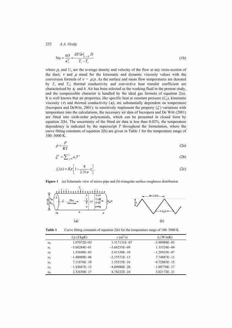
Figure 1 (a) Schematic view of micro-pipe and (b) triangular surface roughness distribution
Table 1 Curve fitting constants of equation 2(b) for the temperature range of 100–3000 K
Cp (J/kgK) v (m2/s) kf (W/mK) a0 1.07072E+03 1.317131E–07 –3.98988E–03 a1 –5.68284E–01 –3.68255E–09 1.35324E–04 a2 1.55698E–03 2.41330E–10 –1.28935E–07 a3 –1.48088E–06 –2.15571E–13 7.74887E–11 a4 7.31876E–10 1.35515E–16 –4.72883E–15 a5 –1.93047E–13 –4.09980E–20 –1.09770E–17 a6 2.32650E–17 4.78222E–24 3.02173E–21

Entropy analysis of laminar-forced convection 253
Among the several definitions for surface roughness available in the literature, the present model is based on the triangular structure of Cao et al. (2006) (Figure 1(b)), where the roughness amplitude and period are characterised by ε and ω, respectively. To investigate the role of surface roughness on the heat and energy transfer performance of laminar flow, amplitude values are varied for ε = 1–50 µm; however, roughness periodicity parameter (ω’ = ω/ε) is kept fixed to ω’ = 2.31, which corresponds to equilateral triangle structure (Cao et al., 2006), in all computations. With the implementation of the amplitude and period, the model of Cao et al. (2006) is numerically characterised by equation 2(c). The Kronecker unit tensor (δi) attains the value of δi = +1 for 0 ≤ z ≤ (2.31/2)ε and δi = –1 for (2.31/2)ε ≤ z ≤ 2.31ε, and the model function ( fε(z)) is repeated in the streamwise direction throughout the pipe length.
2.2 Governing equations
The problem considered here is steady (∂/∂t) = 0, fully developed and the flow direction is coaxial with pipe centreline ( 0),rU Uθ= = thus the velocity vector simplifies to
( , )zV U r z= denoting ∂Uz/∂θ = 0. These justifications are common in several recent numerical studies, on roughness-induced flow and heat transfer investigations, like those of Engin et al. (2004), Koo and Kleinstreuer (2005) and Cao et al. (2006). With these problem definitions and above implementations, for a laminar compressible flow with variable fluid properties, continuity, momentum and energy equations are given as
( ) 0zUz
ρ∂ =∂
(3)
1 ( )z zzz rz
U PU rz z r r z
τρ τ∂ ∂∂ ∂ + = + ∂ ∂ ∂ ∂ (4)
1 ( )
1 ( )
z zz r zz
z zzrz z rz
Q UPe k U rQz r r z z
U U rr r r z
ρ τρ
ττ τ
∂ ∂∂ ∂+ + + + = ∂ ∂ ∂ ∂ ∂ ∂∂ + + + ∂ ∂ ∂
(5)
where internal and kinetic energy terms are defined as e = CvT and 2 / 2zk U= , respectively. Components of the viscous stress tensor (τ) and heat flux terms (Q) can be written as
T zrz
Ur
τ µ ∂=
∂ (6a)
43
T zzz
Uz
τ µ ∂=
∂ (6b)
Tr f
TQr
κ ∂= −∂
(7a)
.Tz f
TQz
κ ∂= −∂
(7b)

254 A.A. Ozalp
The flow boundary conditions are based on the facts that, on the pipe wall no-slip condition and constant heat flux exist and flow and thermal values are maximum at the centreline. At the pipe inlet, pressure and temperature values are known and the exit pressure is atmospheric. Denoting Uz = U(r, z) and T = T(r, z), the boundary conditions can be summarised as follows:
in in
( ) 0 and 0 0
( ) and 0 0
0 , and 0 (Manometric).
rTf
Ur R f z U rr
QT Ur R f z rr r
z P P T T z L P
ε
ε κ
∂= + → = = → =∂
∂ ∂= + → = − = → =∂ ∂
= → = = = → = (8)
The average fluid velocity and temperature and mass flow rate are obtained from
02
2 ( ) ( ) dr R
ro
o
r U r r rU
R
π ρ
ρ π
=
== ∫ (9a)
02
2 ( ) ( ) ( ) ( ) d
( )
r R
pro
o o p o
r U r C r T r r rT
U C R
π ρ
ρ π
=
== ∫ (9b)
02 ( ) ( ) d
r R
o o rm U A r U r r rρ π ρ
=
== = ∫ (9c)
and the shear stress and pipe friction force are defined as
21 d2 d
Tf o o
r R
uC Ur
τ ρ µ=
= = (10a)
0d .
z L
f zF D zπ τ
=
== ∫ (10b)
The non-equilibrium phenomenon of exchange of energy and momentum within the fluid and at the solid boundaries result in entropy generation, which is directly proportional to the lost available work; this concurrence is known as the Gouy-Stodola theorem. For a two-dimensional (r, z) compressible Newtonian fluid flow in cylindrical coordinates, the local rate of entropy generation per unit volume (S )′′′ is symbolised by equation 11(a). As given in equation 11(b), the entropy generation due to finite temperature differences ∆( )TS ′′′ in axial z and in radial r directions is defined by the first term on the right side, the second term stands for the frictional entropy generation ( ).PS∆′′′ Computation of the temperature and the velocity fields through equations (3)–(5) on the problem domain, will produce the input data for equation (11).
2 2 2 2
2 2T Tf T T U US
r z T r zTκ µ ∂ ∂ ∂ ∂ ′′′ = + + + ∂ ∂ ∂ ∂
(11a)
.T PS S S∆ ∆′′′ ′′′ ′′′= + (11b)
Due to the existence of the velocity and temperature gradients in the flow volume, the volumetric entropy generation rate is positive and finite. As the total and volumetric

Entropy analysis of laminar-forced convection 255
average entropy generation rates can be obtained by equation 12(a) and (b), respectively, the average volumetric entropy generation, in non-dimensional form, is evaluated by equation 12(c).
0 02 d d
z L r R
z rS S r r zπ
= =
= =′′′= ∫ ∫ (12a)
2
SSR Lπ
′′′ = (12b)
2
2
Tf TJ SQ
κ′′′= (12c)
∆Be .TSS′′′
=′′′
(12d)
Petrescu (1994) and Bejan (1996) defined the dimensionless parameter of Be. The Be (equation 12(d)) compares the magnitude of entropy generation due to heat transfer to the magnitude of the total entropy generation. While Be > 0.5 the entropy generation due to heat transfer dominates, for Be < 0.5 the entropy generation due to friction leads. When the thermal and frictional generation rates are comparable Be becomes ≈0.5.
2.3 Computational method
Forward difference discretisation is applied in the axial and radial directions, for the two-dimensional marching procedure. The flow domain is divided into m axial and n radial cells (m × n), where the fineness of the computational grids is examined to ensure that the obtained solutions are independent of the grid employed. Initial runs indicated an optimum axial cell number of m = 500, having an equal width of ∆z, whereas, the radial direction is divided into n = 100 cells. Since the velocity and temperature gradients are significant on the pipe walls, the 20% of the radial region, neighbouring solid wall, is employed an adaptive meshing with radial-mesh width aspect ratio of 1.1. The laminar micro-pipe flow with surface roughness and heat flux governs the complete equation set described above; however, for simultaneous handling they need to be assembled into the three-dimensional ‘Transfer Matrix’, consisting of the converted explicit forms of the principle equations. The sufficiently complex structure involves the highly dependent non-linear formulations, where the solution scheme is most likely to face with convergence problems and encounter singularities. Wu and Tseng (2001) applied Direct Simulation Monte Carlo (DSMC) method to a micro-scale gas dynamics problem. Since the influences of surface roughness and surface heat flux conditions are coupled over the meshing intervals of the flow domain, DSMC implementation is an utilised technique especially for gas flow applications with instabilities and for internal flow problems. The benefit of DSMC becomes apparent when either the initial guesses on inlet pressure and inlet velocity do not result in convergence within the implemented mesh or if the converged solution does not point out the desired Re in the pipe. There exists two types of convergence problems (singularities) such that:

256 A.A. Ozalp
• Mach number exceeds 1 inside the pipe • the exit Mach number is lower than or equal to 1 but the exit pressure deviates from
the related boundary condition more than 0.01 Pa. (equation (8)).
Additionally, the ‘Transfer Matrix’ scheme and to the DSMC algorithm are supported by cell-by-cell transport tracing technique, which in return requires much less specific change in programming and enables the application of different types of boundary conditions. In order to perform accurate simulation for inlet/exit pressure boundaries and to sensitively evaluate the balance of heat swept from the micro-pipe walls and the energy transferred in the flow direction, the concept of triple transport conservation is incorporated into the DSMC, where the resulting non-linear system of equations is solved by using the Newton-Raphson method. The streamwise variations of the three primary flow parameters (U, P, T) are investigated. In the case of a convergence problem, U, P and T are investigated up to the singularity point, and then the local velocity is compared with that of the inlet value together with the location of the singularity point wrt to the inlet and exit planes. DSMC method considers the velocity variation and the corresponding pipe length, and modifies the inlet velocity by considering the type of singularity. But if the Re does not fit the required value then both the inlet pressure and velocity are modified in order to either increase or decrease the Re, evaluated at the former iteration step. Thermal equilibrium at each pressure boundary within the mesh is satisfied by simultaneously conserving mass flux and boundary pressure matching. The convergence criteria for the mass flow rate throughout the flow volume are in the order of 0.01% and the deviation of exit pressure from the related boundary condition (equation (8)) is less than 0.01 Pa.
3 Discussion
To comprehensively investigate the influences of surface roughness and heat flux conditions on the second law of thermodynamics and momentum and energy transport mechanisms of the fully developed laminar flow, computations are carried out in a micro-pipe having a diameter of D = 1 mm, which is consistent with the micro-channel definition of Obot (2002), where the pipe length is selected as L = 0.5 m. As the inlet temperature is fixed to Tin = 278 K, computations are performed for Re = 1–2500 and Q = 5–100 W/m2. Surface roughness amplitude is varied within the range of ε = 1–50 µm (ε* = ε/D = 0.001–0.05), where the ε* values are similar to those of Wang et al. (2005) (ε* = 0.005–0.05), Engin et al. (2004) (ε* ≤ 0.08) and Sahin et al. (2000) (ε* ≤ 0.25). Since velocity and TPs are known to have considerable role on entropy generation, numerical discussions are based on profile structures, momentum and heat transfer characteristics. Detailed discussions are presented on the radial and overall entropy generation mechanism together with crosscomparisons among momentum and heat transfer values with those of the second law.
Entropy analysis of laminar-forced convection 257
3.1 Velocity and Temperature Profiles (TPs)
Being the main designator of momentum transfer in the flow direction, VP are presented for three Re and non-dimensional surface roughness cases in Figure 2(a). Computations put forward that the applied heat flux on the lateral solid walls of the microduct had no influence on the VP; thus Figure 2(a) displays the combined impact of Re and ε* on the VP development in comparison with the laminar profile (equation 13(a)) and the turbulent logarithm law that is modified for roughness as given by equation 13(b) (White, 1988), where U* is the friction velocity defined by equation 13(c). The numerical results pointed a maximum Mach number of M = 0.103 for the upper Re limit of Re = 2500, where the highest density variation in the flow direction is 3.1%. Thus the VP, given in Figure 2(a), represent the flow characteristics for the complete pipe length. Moreover to describe the flow regime, shape factors (H) are evaluated by equation 14(a) and compared with the characteristic laminar (Hlam = 3.36) and turbulent (Hturb = 1.70) data, resulting in the intermittency (γ ) values (equation 14(b)). Since friction has direct contribution on entropy generation, friction coefficient (Cf) is evaluated by equation 15(a), compared with the traditional laminar formula (equation 15(b)) and presented in normalised form as Cf* (equation 15(d)).
2( ) 2 1o
U r rU R
= −
(13a)
( ) 2.44ln 8.5*
U r R rU ε
− = +
(13b)
* wUτρ
= (13c)
0
0
( )1 d
( ) ( )1 d
r R
rm
r R
rm m
U r rU
HU r U r rU U
=
=
=
=
−
=
−
∫
∫ (14a)
lam
lam turb
H HH H
γ −=
− (14b)
2
d2d
T
r Rf
o o
Ur
CU
µ
ρ== (15a)
lam16( )RefC = (15b)
0.25turb( ) 0.079RefC −= (15c)
lam
* .( )
ff
f
CC
C= (15d)

258 A.A. Ozalp
Figure 2 (a) Velocity Profiles (VPs) for various Re and ε* cases and (b) Temperature Profiles (TPs) for various Re, ε* and Q cases
Entropy analysis of laminar-forced convection 259
It can be seen from Figure 2(a) that at Re = 500, the lowest surface roughness of ε* = 0.001 had no particular influence to distinguish the profile from that of the laminar; indeed the shape and intermittency factors attained the values of 3.29 and 0.041 implying apparently the laminar character. However, the corresponding values for Re = 1000 and Re = 1500 for ε* = 0.001 are evaluated as H = 3.22 and 3.16 and γ = 0.084 and 0.121 showing the increasing influence of even an inconsiderable surface roughness value at 43% and 65% of the critical Re of 2300. Additionally, the *
fC values showed also augmentation with Re for the same ε* of 0.001 such that *fC is evaluated as 1.028, 1.061 and 1.088 for Re = 500, 1000 and 1500, respectively. On the other hand, the highest surface roughness in the computations (ε* = 0.05) caused significant and clear shifts in the VP from that of the laminar with lower H and higher γ and *
fC values even at the low Re of 500; whereas, the impact of ε* on the flow pattern becomes impressive at the higher Re of 1500 with H = 2.76, γ = 0.362 and * 1.35.fC = These values indicate that a relatively high ε* of 0.05 can turn the flow into almost 36% transitional at the 65% of the critical value of Re = 2300 where the corresponding friction coefficient exceeds the laminar approach by 35%. The VPs of Figure 2(a), especially the near-wall regions (r/R ≥ 0.75) and the centreline (r/R = 0) put forward the growing influence of surface roughness on the flow pattern with Re. Since friction factor is a consequence of the velocity gradient at the wall ((dU/dr)|r = R), the growth of Cf and *fC values is an outcome of the fuller VP with higher ε* and Re. Figure 2(a) additionally implies the role of surface roughness in laminar flow by putting forward the VP transformation from laminar to the initial stages of transitional character even at Re = 1500 with higher Cf and γ and lower H and Uc/Uo values. Furthermore, the gap between the Uc/Uo ratios and the traditional data of Uc/Uo = 2.0 (equation 13(a)) increases both with higher ε* and Re, which also strengths the determinations on transition.
TP development is based not only on the surface heat transfer rates but also on the amount of energy loss (Ψloss) due to viscous dissipation on the solid walls. Figure 2(b) displays the radial variations of temperature values, in non-dimensional form wrt to the centreline value (Tc), for various heat flux, surface roughness and Re. The characteristics are compared with the laminar constant heat flux formula of equation 16(a), where α is the thermal diffusivity (equation 16(b)).
4 222 d 3 1 1( )d 16 16 4
o os T
U R T r rT r Tz R Rα
= − + − (16a)
.TfT
TpC
κα
ρ= (16b)
It can be seen from the figure that roughness implementation has no effect on the TP for the low Re of Re = 500. It can additionally be seen that as the surface temperature (Ts) values of the cases for Q = 50 and 100 W/m2 are above the Tc, the contrary is true for Q = 5 W/m2. The condition of Ts > Tc is expected for heat addition process where the opposite evaluation is an outcome due to the frictional energy losses. Although heat is added through the lateral walls of the duct with a flux of 5 W/m2, this supply is not sufficient enough to meet the amount of energy loss due to friction. Table 2 shows the applied flux and the corresponding total surface heat transfer values (Qs), together with the amount of viscous energy loss (Ψloss) data for three Re and also for the surface

260 A.A. Ozalp
roughness range of 1 6*** 0.001( ) 0.05( ).ε ε ε= − The total heat added through the duct walls (Qs = 0.007854 W) is lower than the energy loss values for Re = 500 for the complete ε* range (Ψloss = 0.0111 – 0.0121 W), where the gap between the Qs and Ψloss values rise in the cases with higher Re. The tabulated data are projected to the plots with significantly deviated curves from the CHF profile of equation 16(a) for Re = 1000 and 1500 at Q = 5 W/m2. The particular case of Re = 500 also shows that, although Ts > Tc condition is valid for Q = 50 and 100 W/m2, the profiles as well imply divergence from equation 16(a) showing significantly lower Ts values when compared with the analytical, which is also a consequence of the frictional behaviour. Table 2 also indicates that, Ψloss values rise with heat flux: as the velocity gradient is known not to vary with flux (Figure 2(a)), the augmentation of shear rates, at the identical Re, can be attributed to the augmented viscosity values at higher temperature values, which is an outcome of the elevated heat flux values. Energy loss and temperature decrease due to friction in laminar flow was also reported in recent work by Koo and Kleinstreuer (2004), Morini (2005) and Celata et al. (2006a, 2006b). Their common findings are wall heating due to viscous dissipation; the dissipated energy resulted in loss of flow temperature even the surface roughness effects were disregarded. Additionally they also indicated that, viscous dissipation is directly related with Re where they experimentally and numerically recorded exponential augmentations in energy loss at high Re. These results show harmony with the present evaluations on heating/cooling TPs of Figure 2(b) and the energy loss data of Table 2. Moreover, Ozalp (2006b, 2006c) also determined power loss in compressible high speed converging nozzle flows due to the frictional activity. With the increase of Re (Re = 1000 and 1500) the impact of ε* on TP becomes more apparent, which can be explained by the expanded and augmented Ψloss ranges of Table 2. Figure 2(b) puts forward that the moderate flux of Q = 50 W/m2 is not sufficient enough to suppress the Ψloss values at Re = 1500, which resulted in the cooling contour TP. Figure 2(b) and Table 2 mutually propose that heat flux addition must be considered by also inspecting the amount of viscous dissipation in the flow domain.
Table 2 Ψloss values for various Re, ε* and Q cases
Q (W/m2) 5 50 100
Qs (W) 0.007854 0.07854 0.15708 Ψloss (W) 1 6* *( )ε ε−
Re = 500 0.0111 – 0.0121 0.0117 – 0.0127 0.0124 – 0.0134 Re = 1000 0.0468 – 0.0549 0.0480 – 0.0563 0.0494 – 0.0578 Re = 1500 0.1109 – 0.1406 0.1128 – 0.1429 0.1150 – 0.1454
3.2 Momentum and heat transfer
3.2.1 Friction coefficient (Cf )
Friction coefficient is not only an indicator parameter for frictional losses but also an outcome of the velocity gradient at the solid wall that were discussed in the previous section. Since the viscous dissipation plays a significant role on the entropy generation, Cf gains higher importance especially due to its direct contribution on the non-dimensional parameter of Be (equation 12(d)). Computational Cf values,

Entropy analysis of laminar-forced convection 261
for various ε* cases, are presented in Figure 3(a), in conjunction with the traditional laminar theory (equation 15(b)), turbulent smooth pipe approximation (equation 15(c)) and also with the available literature-based data. It can be seen from the figure that, for Re < 500 the friction coefficient values, for the complete set of ε* cases (0.001–0.05), are in conjunction with the laminar theory, which indicates that surface roughness does not create a variation in the frictional characteristics of laminar flow. Indeed the experimental data of Kohl et al. (2005), Choi et al. (1991) and Wu and Little (1983) as well show harmony with not only the current Cf determinations but also with equation 15(b) for Re < 500. This coinciding appearance does also verify the highly similar VP of Figure 2(a) (Re = 500), for various ε* cases, with that of the laminar. Current numerical investigations put forward shifts in Cf data from the laminar curve for Re > 500 indicating that the influence of surface roughness becomes apparent with higher Re, which was also recorded by Guo and Li (2003) for microscale flow. As the friction factor values for ε* = 0.001 and ε* = 0.05 are above the laminar theory by 6.1% and 23.1% at Re = 1000, these ratios rise to 8.8% and 34.5% at Re = 1500 designating apparently the onset of transition. These evaluations are similar to Vicente et al.’s (2002) reports on roughness-induced friction factor augmentation and earlier transition. Wang et al. (2005) and Engin et al. (2004) as well reported that the role of surface roughness on friction coefficient expands with Re. The augmentation in Cf values, together with higher flow velocity, is a serious indicator of pressure losses and so occurring entropy rise within the flow volume. As can be seen from Figure 3(a) that most of the available experimental studies on laminar flows, available in the literature, reported higher friction coefficients than those of equation 15(b) for Re > 500 (Kohl et al., 2005; Choi et al., 1991; Wu and Little, 1983). However, the experimental friction factors of Yu et al. (1995) were even below the laminar theory for Re < 2000. On the other hand, the experimental records of Jiang et al. (1995), in the microchannel heat exchanger, were considerably shifted from the laminar data and they fitted their experimental data resulting in the analytical correlations of equation 17(a) and (b) for Re < 600 and Re > 600, respectively.
1.48410RefC −= (17a)
0.551.36Re .fC −= (17b)
They reported that the onset of transition was around Re ≈ 600 for Dh = 0.3 mm and for the ε* in the range of 0.02–0.12. They explained this significantly early occurrence with two reasons:
• due to microchannel behaviour
• because of the sufficiently high surface roughness data.
Actually the present findings show transitional behaviour at Re > 1500 for a larger diameter of 1 mm and lower ε* range, which as a result show harmony with the findings of Jiang et al. (1995) on transition mechanism with low Re.

262 A.A. Ozalp
Figure 3 (a) Cf vs. Re; (b) m vs. Pin and (c) Nu vs. Re for various ε* cases
(a)
(b)

Entropy analysis of laminar-forced convection 263
Figure 3 (a) Cf vs. Re; (b) m vs. Pin and (c) Nu vs. Re for various ε* cases (continued)
(c)
3.2.2 Mass Flow Rate ( )m
Amount of mass flow rate ( )m is directly related with the flow velocity (equation 9(c)), thus Re and the main influencing parameter, for a fixed pipe cross-section and inlet temperature, is the inlet pressure (Pin). Figure 3(b) displays the m variation with Pin for various ε* cases. The augmented Cf values of Figure 3(a) due to higher surface roughness values resulted in increased friction forces counteracting the flow direction. The resistive force resulted in lower mass flow rates at the same inlet pressures, where the difference becomes more considerable in cases with higher m and Re, which is completely in harmony with Cf vs. Re variations of Figure 3(a). Figure 3(b) additionally puts forward that the computed m data are considerably lower than the isentropic operation values due to the mentioned frictional behaviour. Defining discharge coefficient (Cd) with equation 18(a) results in the Cd values of Table 3 for various Re, surface heat flux and roughness scenarios.
real
isend
mCm
= (18a)
0.50.51 Re
8dDCL
=
(18b)
0.5
.2d
mCA P
ρρ
= ∆ (18c)

264 A.A. Ozalp
Table 3 Cd values for various Re, ε* and Q cases
Cd
Computational 1 6**( )ε ε−
Q(W/m2) 5 50 100 Eq. 18(b) Eq. 18(c)
Re = 500 0.1237 – 0.1190 0.1216 – 0.1171 0.1195 – 0.1152 0.1250 0.1223
Re = 1000 0.1735 – 0.1618 0.1722 – 0.1607 0.1707 – 0.1594 0.1768 0.1696
Re = 1500 0.2110 – 0.1919 0.2100 – 0.1911 0.2089 – 0.1902 0.2165 0.2037
Re = 2000 0.2423 – 0.2160 0.2414 – 0.2154 0.2405 – 0.2147 0.2500 0.2307
Re = 2500 0.2696 – 0.2369 0.2689 – 0.2364 0.2681 – 0.2359 0.2795 0.2529
The tabulated data indicate not only that the Cd values increase with Re but also the Cd ranges expand in higher Re cases revealing the enhanced role of ε* on the flow rate values. Ozalp (2006b, 2006c) reported similar findings on the Cd-ε relation in compressible converging nozzle flows. On the other hand, the present numerical values are also compared with the analytical solutions of Phares et al. (2005) (equation 18(b)) and Sahin and Ceyhan (1996) (equation 18(c)). It can be seen that, although quite close, the proposed equation of Phares et al. (2005) deviate from that of Sahin and Ceyhan (1996) for Re > 1250 and Pin > 7.5 kPa. However, either of the methods show significant similarities with the present evaluations for Re < 1000; besides at higher Re especially the solution of equation 18(c) deviate from the computational values. The proposed equation of Phares et al. (2005) appears to be consistent with the numerical results for the highest roughness scenario of ε* = 0.05 for the complete Re range. The inconsistency of equations 18(b)–(c) with the low ε* cases can be explained by the facts that: neither of the analytical solutions involve surface roughness as an effective parameter on the momentum rates; moreover, in the present work the flow turns out to be of transitional type for Re > 1500. Additionally, Table 3 interprets the slight decrease of Cd data with heat flux values, which is a consequence of higher viscosity, frictional forces and power loss values as discussed through Table 2.
3.2.3 Heat Transfer (Nu)
Surface heat transfer values, in terms of Nu, are displayed in Figure 3(c) for various Re and ε* cases. It can be seen that up to Re ≈ 100 neither flow velocity nor surface roughness produced a sensible effect on heat transfer rates and Nu attained the value of ~4.04 being between the characteristics markers of Nu = 4.36 (constant heat flux) and Nu = 3.66 (constant surface temperature). Whereas for Re = 100, computations indicated a Nu of 4.08, which is observed to augment with Re. Likewise, the heat transfer measurements of Wen et al. (2003), for a D = 2 mm pipe, and Vicente et al. (2002), for a D = 16 mm pipe, pointed out constant Nu of ~4 for Re < 300 (Wen et al., 2003) and Nu of ~4.36 for Re < 700 (Vicente et al., 2002), after that an increase of Nu was recorded in both of the studies. Since enhancement of heat transfer rates is an indicator for transitional regime, the numerical and the experimental data of Wen et al. (2003) and
Entropy analysis of laminar-forced convection 265
Vicente et al. (2002) put forward that in small scale pipes transition onset is reversely proportional to pipe diameter and can be reached at comparably lower Re than the traditional value of Re = 2300. Figure 3(c) additionally reveals that the impact of surface roughness on heat transfer mechanism becomes apparent for Re > 100; computations put forward that ε elevates Nu, where this influence is determined to grow with Re; such that the Nuε* = 0.05/Nuε* = 0.001 ratio attains the values of 1.086, 1.168 and 1.259 for Re = 500, 1000 and 1500, respectively. Kandlikar et al. (2003) also experimentally recorded augmentations in Nu with surface roughness for the ε* range of 0.0018–0.0028, and Wu and Cheng (2003) experimentally reported the increased role of ε on Nu at higher Re. The experimental data of Kandlikar et al. (2003) (for Re ≥ 500), Obot (2002) (for Re ≥ 1000) and Wu and Little (1983) (for Re ≥ 1000) are reasonably in harmony with the current numerical outputs; however, Wu and Little (1983) reported lower heat transfer rates than those of both the present work and other considered studies for Re < 1000.
3.3 Entropy generation
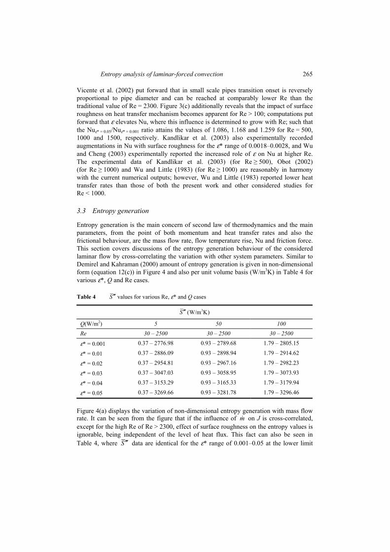
Entropy generation is the main concern of second law of thermodynamics and the main parameters, from the point of both momentum and heat transfer rates and also the frictional behaviour, are the mass flow rate, flow temperature rise, Nu and friction force. This section covers discussions of the entropy generation behaviour of the considered laminar flow by cross-correlating the variation with other system parameters. Similar to Demirel and Kahraman (2000) amount of entropy generation is given in non-dimensional form (equation 12(c)) in Figure 4 and also per unit volume basis (W/m3K) in Table 4 for various ε*, Q and Re cases.
Table 4 S′′′ values for various Re, ε* and Q cases
3(W/m K)S′′′
Q(W/m2) 5 50 100 Re 30 – 2500 30 – 2500 30 – 2500
ε* = 0.001 0.37 – 2776.98 0.93 – 2789.68 1.79 – 2805.15
ε* = 0.01 0.37 – 2886.09 0.93 – 2898.94 1.79 – 2914.62
ε* = 0.02 0.37 – 2954.81 0.93 – 2967.16 1.79 – 2982.23
ε* = 0.03 0.37 – 3047.03 0.93 – 3058.95 1.79 – 3073.93
ε* = 0.04 0.37 – 3153.29 0.93 – 3165.33 1.79 – 3179.94
ε* = 0.05 0.37 – 3269.66 0.93 – 3281.78 1.79 – 3296.46
Figure 4(a) displays the variation of non-dimensional entropy generation with mass flow rate. It can be seen from the figure that if the influence of m on J is cross-correlated, except for the high Re of Re > 2300, effect of surface roughness on the entropy values is ignorable, being independent of the level of heat flux. This fact can also be seen in Table 4, where S ′′′ data are identical for the ε* range of 0.001–0.05 at the lower limit

266 A.A. Ozalp
(Re = 30) of the tabulated Re range. However, at the upper limit (Re = 2500) the ratio of * 0.05 * 0.001/S Sε ε= =′′′ ′′′ attains the similar value of 1.18 for the complete imposed heat fluxes,
which points out an increase of up to 18% in the high Re cases. Indeed, the roughness-induced augmentation of J is also exposed in Figure 4(a) through the zoomed plots for Re = 2500. Figure 4(a) additionally implies that there exist two Re intervals regarding the role of mass flow rate on entropy generation. Up to a exergo-critical Re ((Recr)ex), J decreases with m where these critical limits are found to increase with heat flux such that computations revealed these boundaries as (Recr)ex ≈ 6, 20 and 40 for Q of 5, 50 and 100 W/m2, respectively. Above these limits there exists direct proportion among J and m , which puts forward that entropy generation grows with mass flow rate. Ratts and Raut (2004) also determined minimum entropy generation for certain Re both in laminar and turbulent flows. Additionally, the growth of entropy with mass flow rate was also reported by Lin and Lee (1998) for heat exchangers.
Relation of entropy generation with temperature rise (∆T) is plotted in Figure 4(b). For all heat flux applications, J values evaluated at higher ∆T cases (low Re) are significantly lower than those of the low ∆T flows (high Re). This outcome is completely in harmony with the discussions on J m− relation of Figure 4(a). Additionally, the exergo-critical Re are also indicated in Figure 4(b), where J shows different variation characters with ∆T as well. The roughness effect on J is inspected by the zoomed plots for Re = 2500, indicating emerging role of ε* on J at high Re. But, the zoomed plots further put forward that the cooling rates, due to the frictional losses are higher at the low Q of 5 W/m2 with the ∆T range records of –8.8oC (ε* = 0.001) to –12.6oC (ε* = 0.05). For the high Q of 100 W/m2, although still cooling exits, these ∆T limits rise to –5.2oC and –9.2oC. Besides the J – ∆T interrelation, with the aid of the zoomed plots, Figure 4(b) interprets the augmented role of the frictional behaviour on the cooling activity, where these records show harmony with the discussions through Figure 2(b). Since the generated entropy is composed of two terms, :TS∆′′′ the thermal part and :PS∆′′′ the frictional part, a deeper survey by decomposing the overall generation rate into sub-sections will be helpful in understanding the entropy mechanism. Figure 5 displays the variation of the thermal and frictional parts of entropy generation on a logarithmic plot. The effects of ε* come into sight towards the end of heating period, thus as augmentations are observed in ,PS∆′′′ comparably minor reductions are determined in
TS∆′′′ data. Although the onset of the defined region varies, the mentioned character is valid for all heat flux applications. PS∆′′′ values are computed to increase continuously with Re; since PS∆′′′ is directly associated with velocity, mass flow rate and Re, augmentations become more recognisable in higher Re. As ε* creates a decreasing impact on TS∆′′′ around the thermally critical Re ((Recr)th ≈ 400, 1300 and 1700 for Q = 5, 50 and 100 W/m2, respectively), above (Recr)th surface roughness augments the TS∆′′′ data. Figure 5 additionally displays that below (Recr)ex, TS∆′′′ values are comparably higher than
.PS∆′′′ The reason can be explained with the significantly high ∆T and heat transfer-based entropy generation ( )TS∆′′′ values; and also because of the low frictional forces and frictional activity-based entropy generation ( )PS∆′′′ due to the slow flow velocities, where these can also be seen in Figure 4(b). Ratts and Raut (2004) also indicated augmented thermal entropy generation for Re < (Recr)ex and elevated frictional entropy generation for

Entropy analysis of laminar-forced convection 267
Re > (Recr)ex. Supporting these determinations, Table 4 interprets the significant increase rates in the S ′′′ values at Re = 30 with higher heat flux applications, that is mainly based on the rise of the .TS∆′′′ As the ratio of 50 5/Q QS S= =′′′ ′′′ is 2.51 for Re = 30, it decreases to ~1.0045 for Re = 2500. The minor ratio at Re = 2500 is due to the slightly higher temperature values (~2C – Figure 4(b)) at Q = 50 W/m2, that causes minor grows in flow viscosity, frictional activity and .PS∆′′′ Figure 5 shows as well that, besides the augmentations in either of the TS∆′′′ and PS∆′′′ around Re ≈ 2500, PS∆′′′ becomes dominant to
TS∆′′′ by occupying the major portion in the overall entropy generation ( ).S ′′′ Figure 5 covers essential information not only for the clarification of the (Recr)ex occurrence in Figures 4(a) and (b), but also for the explanation of the fact that the major fraction of the total entropy generation is due to the frictional behaviour at the high m and Re and low ∆T scenarios.
3.4 Bejan number profiles
Be, as defined by equation 12(d), is the ratio of the thermal-based entropy generation rate ( )TS∆′′′ to the total generation ( ).S ′′′ As can also be seen in Figure 5, since ε* plays an augmenting role on TS∆′′′ in cooling cases, in Figure 6 ε* results in increased Be for the complete set of cooling scenarios (Q = 5 W/m2 and Re > 400, Q = 50 W/m2 and Re > 1300, Q = 100 W/m2 and Re > 1700) in the entire radial domain (0 < r/R < 1). But, for heating the impact of ε* on Be is opposite for the centreline (r/R = 0) and solid wall (r/R = 1) neighbourhoods. The reason can be clarified with the high wall temperature values in heating conditions, which cause the flow viscosity values to rise locally. As a consequence, the frictional activity in the regions close to the pipe walls grows, causing the PS∆′′′ portion to increase in the total generation. This structure becomes identifiable especially in the cases of Re = 500–1000 and Q = 50 W/m2 and Re = 1000–1500 and Q = 100 W/m2. Besides, Figure 6 points out that, the near-wall decreasing role of ε* on Be expands for fixed heat flux values with Re; additionally, the radial region of the heating-based decreasing role, also enlarges. Such that for Q = 50 W/m2, as the defined region is 0.77 ≤ r/R ≤ 1 for Re = 500, the corresponding one is 0.54 ≤ r/R ≤ 1 for Re = 1000; whereas, at the heat flux of Q = 100 W/m2 for Re = 500, 1000 and 1500 these radial zones become 0.79 ≤ r/R ≤ 1, 0.72 ≤ r/R ≤ 1 and 0.41 ≤ r/R ≤ 1, respectively. On the other hand, being independent of Re, ε and Q, in the entire flow scenarios Be attains very close values to 1 at the centreline (r/R = 0) of the pipe. This not only validates that the frictional activity ( )PS∆′′′ in the centreline region is negligible, but also puts forward that the major portion of the total entropy generation is thermal based ( ).TS∆′′′ However, the opposite outcome is in effect for the wall neighbourhood, where PS∆′′′ dominates the entropy generation regardless of .PS∆′′′

268 A.A. Ozalp
Figure 4 (a) J vs. m and (b) J vs. ∆T for various ε* and Q cases

Entropy analysis of laminar-forced convection 269
Figure 5 TS∆′′′ vs. PS∆′′′ for various ε* and Q cases

270 A.A. Ozalp
Figure 6 Be profiles for various Re, ε* and Q cases
Entropy analysis of laminar-forced convection 271
4 Conclusion
Laminar, compressible, temperature-dependent property continuity, momentum and energy equations are solved for a forced convection micro-pipe flow with wall roughness conditions. Computations were performed to obtain the contribution of surface heat flux and wall roughness on the energy and exergy characteristics of laminar pipe flow. The following conclusions are attained:
• a relatively high ε* of 0.05 is determined to turn the flow into almost 36% transitional at the 65% of the critical value of Re = 2300, where the corresponding friction coefficient exceeds the laminar approach by 35%
• the impact of ε* on TPs become more apparent at high Re, which is an outcome of the augmented viscous dissipation values
• the shifts in Cf and Nu data, from those of the traditional laminar values, for Re > 500 and Re > 100, respectively, indicate that the influence of surface roughness on the frictional and heat transfer behaviours become noticeable at higher Re
• there exist exergo-critical Re, below which entropy generation is determined to decrease with mass flow rate; moreover, these critical limits are found to increase with heat flux
• the influence of both the heat transfer and the frictional activity on entropy generation is evaluated to expand with mass flow rate and Re
• the effect of surface roughness on entropy generation is ignorable at low Re, however, at the upper Re limit of 2500 the ratio of * 0.05 * 0.001/S Sε ε= =′′′ ′′′ attains 1.18, pointing out an increase of up to 18% due to ε in high Re cases
• the effects of ε on TS∆′′′ and PS∆′′′ come into sight towards the end of heating period, thus as augmentations are observed in ,PS∆′′′ comparably minor reductions are recorded in TS∆′′′ data
• as Re is increased to Re ≈ 2500, PS∆′′′ becomes dominant to TS∆′′′ by occupying the major portion in the overall entropy generation
• ε* causes augmentations in Be for the complete set of cooling scenarios in the entire radial domain, but for heating, the impact of ε* on Be is opposite for the centreline and solid wall neighbourhoods.
References Bejan, A. (1996) Entropy Generation Minimization, CRS Press, Boca Raton. Cao, B.Y., Chen, M. and Guo, Z.Y. (2006) ‘Effect of surface roughness on gas flow in
microchannels by molecular dynamics simulation’, International Journal of Engineering Science, Vol. 44, pp.927–937.

272 A.A. Ozalp
Celata, G.P., Cumo, M., McPhail, S. and Zummo, G. (2006a) ‘Characterization of fluid dynamic behaviour and channel wall effects in microtube’, International Journal of Heat and Fluid Flow, Vol. 27, pp.135–143.
Celata, G.P., Morini, G.L., Marconi, V., McPhail, S.J. and Zummo, G. (2006b) ‘Using viscous heating to determine the friction factor in microchannels – an experimental validation’, Experimental Thermal and Fluid Science, Vol. 30, pp.725–731.
Choi, S.B., Barron, R.F. and Warrington, R.O. (1991) ‘Fluid flow and heat transfer in microtubes’, Micromech. Sensors Actuat. Syst., Vol. 32, pp.123–134.
Demirel, Y. and Kahraman, R. (2000) ‘Thermodynamic analysis of convective heat transfer in an annular packed bed’, International Journal of Heat and Fluid Flow, Vol. 21, pp.442–448.
Engin, T., Dogruer, U., Evrensel, C., Heavin, S. and Gordaninejad, F. (2004) ‘Effect of wall roughness on laminar flow of Bingham plastic fluids through microtubes’, Journal of Fluids Engineering-ASME Transactions, Vol. 126, pp.880–883.
Granovskii, M., Dincer, I. and Rosen, M.A. (2006) ‘Application of oxygen ion-conductive membranes for simultaneous electricity and hydrogen generation’, Chemical Eng. Journal, Vol. 120, pp.193–202.
Guo, Z.Y. and Li, Z.X. (2003) ‘Size effect on microscale single-phase flow and heat transfer’, International Journal of Heat and Mass Transfer, Vol. 46, pp.149–159.
Incropera, F.P. and DeWitt, D.P. (2001) Fundamentals of Heat and Mass Transfer, Wiley, New York.
Jiang, X.N., Zhou, J.Y., Yao, Y.L. and Ye, X.Y. (1995) ‘Micro-fluid flow in microchannel’, Proc. Transducers, Vol. 95, pp.317–320.
Kandlikar, S.G., Joshi, S. and Tian, S. (2003) ‘Effect of surface roughness on heat transfer and fluid flow characteristics at low Reynolds numbers in small diameter tubes’, Heat Transfer Engineering, Vol. 24, pp.4–16.
Kohl, M.J., Abdel-Khalik, S.I., Jeter, S.M. and Sadowski, D.L. (2005) ‘An experimental investigation of microchannel flow with internal pressure measurements’, International Journal of Heat and Mass Transfer, Vol. 48, pp.1518–1533.
Koo, J. and Kleinstreuer, C. (2004) ‘Viscous dissipation effects in microtubes and microchannels’, International Journal of Heat and Mass Transfer, Vol. 47, pp.3159–3169.
Lin, W.W. and Lee, D.J. (1998) ‘Second-Law analysis on wavy plate fin-and-tube heat exchangers’, Journal of Heat Transfer-ASME Transactions, Vol. 120, pp.797–801.
Morini, G.L. (2005) ‘Viscous heating in liquid flows in micro-channels’, International Journal of Heat and Mass Transfer, Vol. 48, pp.3637–3647.
Obot, N.T. (2002) ‘Toward a better understanding of friction and heat/mass transfer in microchannels – a literature review’, Microscale Thermophysical Engineering, Vol. 6, pp.155–173.
Ozalp, A.A. (2006a) ‘Nonadiabatic and frictional constant area duct flow: a visual software based simulation for compressible systems’, Computer Applications in Engineering Education, Vol. 14, pp.64–75.
Ozalp, A.A. (2006b) ‘A computational study to predict the combined effects of surface roughness and heat flux conditions on converging-nozzle flows’, Transactions of the Canadian Society for Mechanical Engineering, Vol. 29, pp.67–80.
Ozalp, A.A. (2006c) ‘Numerical analysis of choked converging nozzle flows with surface roughness and heat flux conditions’, Sadhana-Academy Proceedings in Engineering Sciences, Vol. 31, pp.31–46.
Ozgener, L., Hepbasli, A. and Dincer, I. (2006) ‘Investigation of the energetic and exergetic performance of the Gonen geothermal district heating system’, Proc. Instn. Mech. Engrs-Part A, Vol. 220, pp.671–679.

Entropy analysis of laminar-forced convection 273
Petrescu, S. (1994) ‘Comments on the optimal spacing of parallel plates cooled by forced convection’, International Journal of Heat and Mass Transfer, Vol. 37, pp.1283–1283.
Phares, D.J., Smedley, G.T. and Zhou, J. (2005) ‘Laminar flow resistance in short microtubes’, International Journal of Heat and Fluid Flow, Vol. 26, pp.506–512.
Pretot, S., Zeghmatib, B. and Caminat, P. (2000) ‘Influence of surface roughness on natural convection above a horizontal plate’, Advances in Engineering Software, Vol. 31, pp.793–801.
Ratts, E.B. and Raut, A.G. (2004) ‘Entropy generation minimization of fully developed internal flow with constant heat flux’, Journal of Heat Transfer-ASME Transactions, Vol. 126, pp.656–659.
Sahin, A.Z. (1998) ‘Second-Law analysis of laminar viscous flow through a duct subjected to constant wall temperature’, Journal of Heat Transfer-ASME Transactions, Vol. 120, pp.77–83.
Sahin, B. and Ceyhan, H. (1996) ‘Numerical and experimental analysis of laminar flow through square-edged orifice with variable thickness’, Trans. Inst. Meas. Control, Vol. 178, pp.166–174.
Sahin, A.Z., Zubair, S.M., Al-Garni, A.Z. and Kahraman, R. (2000) ‘Effect of fouling on operational cost in pipe flow due to entropy generation’, Energy Conversion and Management, Vol. 41, pp.1485–1496.
Sahin, A.D., Dincer, I. and Rosen, M.A. (2006) ‘Thermodynamic analysis of wind energy’, International Journal of Energy Research, Vol. 30, pp.553–566.
Sheikh, A.K., Zubair, S.M., Younas, M. and Budair, M.O. (2001) ‘Statistical aspects of fouling processes’, Proc. Instn. Mech. Engrs-Part E, Vol. 215, pp.331–354.
Vicente, P.G., Garcia, A. and Viedma, A. (2002) ‘Experimental study of mixed convection and pressure drop in helically dimpled tubes for laminar and transition flow’, International Journal of Heat and Mass Transfer, Vol. 45, pp.5091–5105.
Wang, H., Wang, Y. and Zhang, J. (2005) ‘Influence of ribbon structure rough wall on the microscale Poiseuille flow’, Journal of Fluids Engineering-ASME Transactions, Vol. 127, pp.1140–1145.
Wen, M.Y., Jang, K.J. and Yang, C.C. (2003) ‘Augmented heat transfer and pressure drop of strip-type inserts in the small tubes’, Heat and Mass Transfer, Vol. 40, pp.133–141.
White, F.M. (1988) Fluid Mechanics, McGraw-Hill, Singapore. Wu, P. and Little, W.A. (1983) ‘Measurement of friction factors for the flow of gases in very fine
channels used for microminiature Joule–Thompson refrigerators’, Cryogenics, Vol. 23, pp.273–277.
Wu, J.S. and Tseng, K.C. (2001) ‘Analysis of micro-scale gas flows with pressure boundaries using direct simulation Monte Carlo method’, Computers and Fluids, Vol. 30, pp.711–735.
Wu, H.Y. and Cheng, P. (2003) ‘An experimental study of convective heat transfer in silicon microchannels with different surface conditions’, International Journal of Heat and Mass Transfer, Vol. 46, pp.2547–2556.
Yu, D., Warrington, R., Baron, R. and Ameel, T. (1995) ‘An experimental and theoretical investigation of fluid flow and heat transfer in microtubes’, ASME/JSME Thermal Eng. Conf. 1, pp.523–530.
Zimparov, V. (2002) ‘Energy conservation through heat transfer enhancement techniques’, International Journal of Energy Research, Vol. 26, pp.675–696.
274 A.A. Ozalp
Nomenclature
a Curve fit constants A Cross sectional area (m2)
Be Bejan number Cd Discharge coefficient Cf Friction coefficient
*fC Normalised friction coefficient
Cv Constant volume specific heat (J/kgK) Cp Constant pressure specific heat (J/kgK) D Diameter (m) e Internal energy per unit mass (J/kg)
fε(z) Surface roughness model function
Ff Friction force (N) h Convective heat transfer coefficient (W/m2K) H Shape factor J Non-dimensional entropy generation k Kinetic energy per unit mass (J/kg) L Pipe length (m)
m Mass flow rate (kg/s)
M Mach number Nu Nusselt number P Static pressure (Pa) Q Surface heat flux (W/m2) R Radius (m), gas constant (J/kgK) Re Reynolds number S Total entropy generation (W/K)
S′′′ Total volumetric entropy generation (W/m3K)
PS∆′′′ Frictional volumetric entropy generation (W/m3K)
TS∆′′′ Thermal volumetric entropy generation (W/m3K)
T Temperature (K) U Axial velocity (m/s)
V Velocity vector
Greek letters
α Thermal diffusivity (m2/s)
ε Roughness amplitude (mm)
ε* Non-dimensional surface roughness (=ε/D)
κf Thermal conductivity of fluid (W/mK)

Entropy analysis of laminar-forced convection 275
Greek letters
γ Intermittency
µ Dynamic viscosity (Pa.s)
ρ Density (kg/m3)
τ Shear stress (Pa)
ξ Air properties
Ψloss Energy loss (W)
ω Roughness period (mm)
Subscripts c, s Center, surface i Dimension in Inlet lam Laminar m, o Maximum, mean
r, θ, z Radial, peripheral, axial
turb Turbulent Superscripts T Temperature dependency _ Volumetric average