environment protection agency office of environmental ... mon guid note _ag2... · page 1 of 97...
TRANSCRIPT

Page 1 of 97
Environment Protection Agency
Office of Environmental Enforcement (OEE)
Air Emissions Monitoring Guidance Note #2 (AG2)
Environmental Protection Agency
Johnstown Castle Estate
Wexford, Ireland.

AIR EMISSION MONITORING GUIDANCE NOTE #2 (AG2)
2
All or parts of this publication may be reproduced without further permission, provided the source is acknowledged.
Although every effort has been made to ensure the accuracy of the material contained in this publication, complete accuracy cannot be guaranteed. Neither the Environmental Protection Agency nor the author(s) accept any responsibility whatsoever for loss or damage occasioned or claimed to have been occasioned, in part or in full, as a consequence of any person acting, or refraining from acting, as a result of a matter contained in this publication.
Acknowledgments
This document has been prepared on behalf of the Environmental Protection Agency by:
Nicholas Kenny, SiteRIGHT Environmental (Ireland)
Dave Curtis, DRC Consultancy Services (UK)
With the assistance of :
Simon Medhurst, Smedstack Environmental (UK)
The Environmental Protection Agency (EPA) wishes to express its appreciation to the following organisations for their contributions in various ways towards the preparation of this document:
The Environment Agency of England and Wales
The Source Testing Association.
The National Standards Authority of Ireland. .
The following EPA staff were centrally involved in the development and review of the document:
Mr Peter Webster, Dr Ian Marnane, and Mr Tony Dolan.
and with special thanks to the contribution of the following EPA staff:
Mr Michael Mc Donagh, Mr Martin O’Reilly, Mr Michael Owens, Ms Eileen Butler, and Ms Edín Christie.

AIR EMISSION MONITORING GUIDANCE NOTE #2 (AG2)
3
Contents
Preface 6
1 Introduction 8
1.1 The Irish Regulatory system 8
1.2 Licence compliance monitoring 8
1.3 Scope of guidance note 9
1.4 How to use this guidance note 10
1.5 Other sources of information on stack emission monitoring 12
2 Health and Safety 14
2.1 Health &Safety law 15
2.2 The STA yellow book 15
3 Stack emission monitoring – first principles 16
3.1 Types of monitoring 16
3.2 Units of measurement 18
3.3 Reference quantities 18
4 Planning and factors affecting the monitoring process 20
4.1 Planning to meet the monitoring objective 21
4.2 IPPC compliance monitoring 21
4.3 Measurement Uncertainty 23
4.4 Measurement Traceability 24
5 Commonly measured pollutants – an overview 25
5.1 Total particulate 25
5.2 Combustion gases 27
5.3 Inorganic gases 28
5.4 Metals and metal species 28
5.5 Organic gases (total) 29
5.6 Organic gases (speciated) 30
5.7 Formaldehyde 31
5.8 Dioxins 31
5.9 Flow rate 33

AIR EMISSION MONITORING GUIDANCE NOTE #2 (AG2)
4
5.10 Reference quantities 33
5.11 Colour indicating tubes 34
6 The Equipment 35
6.1 Types of monitoring equipment 35
6.2 Equipment suitability and fitness for purpose 36
6.3 Equipment calibration 37
6.4 Equipment management 37
6.5 Certification of Equipment 38
7 The Person 39
7.1 Levels of personal competency 39
7.2 Trainee 39
7.3 Technician 39
7.4 Team leader 40
7.5 Advanced competencies in specific technical areas 41
8 The Organisation 42
8.1 License requirements 42
8.2 Accreditation of monitoring organisation 42
8.3 Accreditation of stack emissions monitoring 43
8.4 Management requirements 43
8.5 Technical requirements 44
8.6 Proficiency testing 46
9 Standard Methods 47
9.1 Irish standards 47
9.2 Hierarchy of standards 47
9.3 An index of preferred methods 48
9.4 Deviation and validation 49
9.5 Future standards 49
10 The Monitoring report 50
10.1 License requirements 50
10.2 General requirements for the content of monitoring reports 50
10.3 Data Rounding and Treatment of results below the detection limit 51
AIR EMISSION MONITORING GUIDANCE NOTE #2 (AG2)
5
10.4 Good reporting practice 51
Appendices 53
Appendix 1 – Index of Preferred Methods 54
Appendix 2 – Stack emission monitoring - Audit checklist 82
Appendix 3 – Calculations 87
Appendix 4 – Site review (reconnaissance visit) 89
Appendix 5 – Template, Site specific protocol 90
Appendix 6 - Work file 92
Appendix 7 - Monitoring records 93
Appendix 8, - Stack emission monitoring report 94
References 97

AIR EMISSION MONITORING GUIDANCE NOTE #2 (AG2)
6
Preface
A summarised version of this Air Emissions Monitoring Guidance Note #2 (AG2) is to be published by the end of 2007, and the published document may be ordered from the Agency’s publication office, details of which are available on the Agency website at ww.epa.ie.
The Office of Environmental Enforcement (OEE) is one of the five offices in the Environmental Protection Agency. The OEE’s functions include the regulation of activities licensed under the EPA and WMA Acts. It is the policy of the OEE to provide information and advice via published guidance to those it regulates to secure environmental improvements while ensuring value for money.
This Air Emission Monitoring Guidance Note #2 (AG2) is one of a series of guidance notes that the OEE has planned on the general theme of air pollution monitoring. A forerunner to this document is Guidance Note No. 1 Air Emissions Sampling Facilities (AG1) which describes the facilities that must be provided for the safe and effective monitoring of emissions.
The guidance note is intended for use by all Agency staff, (e.g. licensing and enforcement staff), the licensed operator and test houses that provide an air emissions monitoring service. By raising awareness among Agency staff and operators of current best practice in stack testing, so the test houses must ensure that they are providing a comparable standard of service. The Agency advises licensees to have regard to this guidance when outsourcing their emission monitoring programme
Throughout the guidance note there are examples given of licence conditions which are typical of those found in Irish IPPC licences. In reality, licence conditions will vary somewhat from one licence to the next, so reference should be made to the current licence document for the site to determine the legal obligation for monitoring.
In some existing IPPC licences methods prescribed for monitoring atmospheric emissions may differ from the recommendations of this guidance. These instances can be dealt with on a case by case basis and alterations to the monitoring methods may be permitted with the prior approval of the Agency. New and revised licenses should seek to adopt the recommendations of this guidance.
This is the first air monitoring guidance issued by the Agency and represents a move aimed at improving the overall quality of the stack emission monitoring. The programme of monitoring will depend on the nature and complexity of the site operations. The use of best practice in atmospheric source monitoring is an important strand in operators’ efforts to protect the environment and licensed operators should ensure that the practices described in this guidance are applied to their monitoring programmes as soon as reasonably practicable.
MCERTS
A decision by the Environment Agency (EA), the competent authority for England and Wales, that MCERTS be a mandatory requirement of permits issued under their new IPPC permitting scheme, prompted the UK stack testing market to seek and achieve MCERTs accreditation over a number of years. The EPA (Agency) recognises the many merits of the MCERTS scheme and has encouraged monitoring companies to continue to seek accreditation to MCERTS through UKAS (UK Accreditation Service). The Agency has also encouraged the use of MCERTS certified equipment, (or equivalent) and the personal certification by Irish field technicians through the scheme.
The Agency currently requires MCERTS for their own personnel and contractors who measure significant air emissions, particularly dioxins, at facilities. For the purposes of consistency, efficiency and confidence the Agency will extend the MCERTS requirement (or it’s equivalent) for monitoring and laboratory personnel (INAB or UKAS accreditation) who are carrying out air monitoring and

AIR EMISSION MONITORING GUIDANCE NOTE #2 (AG2)
7
analyses of licensed incinerator emissions for IPPC and waste facilities, which fall under the European Directive for the incineration of waste (2000/76/EC), otherwise known as WID plant.
The requirement will also apply to all emission sources where dioxin monitoring is specified, including those IPPC sites with on site incinerators, unless the operator can demonstrate an alternative which can deliver equivalent levels of confidence. For these sites, the MCERTS requirement would apply to a minimum of one full air monitoring campaign per annum. Any other monitoring within this twelve-month period for parameters other than dioxins could be undertaken by non-certified personnel.
Where operators meet the MCERTS requirements the need for duplicate Agency monitoring may be removed, and this could then be reflected in the monitoring charges.
This requirement may later be expanded to cater for the following facilities or circumstances:
• Large Combustion Plant (2001/80/EC), otherwise known as LCP plant, for some or all of the parameters that would typically be licensed (elv's) at these facilities following further assessment and consultation with the relevant sector.
• For IPPC and waste sites with atmospheric emissions that are giving rise to concern and where there is a requirement to ensure that specified monitoring and analyses on certain priority pollutants is carried out using MCERTS personnel.
• On a case-by-case basis having regard to the nature of the emissions and the sensitivity of the receiving environment, (e.g. using a risk based approach).
• The Agency will only consider MCERTS requirements for other sectors following further assessment and consultation with the relevant sectors.
At the time of development of this Guidance Note, a document is being prepared by CEN/TC 264 working group (WG 19) that provides for the application of ISO 17025 to periodic stack test measurements. The document is a CEN Technical Specification entitled; CEN/TS (WI264063), Air Quality – Measurement of stationary source emissions – Application of EN ISO/IEC 17025:2000 to periodic stack measurements. The completed document will provide a basis for the accreditation of test houses across Europe by their respective accreditation bodies. It is intended to revise this Guidance note, if necessary, to include the requirement of the CEN technical specification.
Revision of this document.
This guidance note will be the subject of periodic review and amendment. The most recent version of this note is available on the Agency website: http://www.epa.ie/ if you have any particular queries on this document then please contact Mr. Tony Dolan at [email protected]

AIR EMISSION MONITORING GUIDANCE NOTE #2
Page 8 of 97
1 Introduction
This guidance note (AG2) was commissioned by the Agency to provide information on the subject of air emission monitoring in the Irish context. The monitoring of air pollution at source is colloquially known as stack testing and it is this term that will used in this guidance.
Stack testing in Ireland prior to 1994 was confined mainly to those sites that were licensed under the Air Pollution Act 1987. A small number of test houses provided a service to those facilities that were required to submit self-monitoring data to the body charged with their regulation (the Local Authority). The Irish market for commercial stack testing was relatively small in comparison to the UK which had a history of heavy industry that was regulated originally by Her Majesty’s Inspectorate of Pollution (HMIP).
The HMIP published a series of guidance notes on the subject of stack testing, these notes have now been replaced by a series of Environment Agency (EA) (who regulate England and Wales) publications. Another rich source of information was the United States Environmental Protection Agency (US EPA) which published some very prescriptive standard methods for the measurement of source emissions. These methods remain in use and can be found on the US EPA website.
While standard methods were published in France, Germany and other EU countries, many of these were not in the English language, therefore it was the American and UK publications that were most often used in Ireland. This situation has been changing in recent years due to the development of European Standard methods and their mandatory status in all EU member states. The number of Irish standard methods for the measurement of air pollutants will continue to increase over time.
1.1 The Irish Regulatory system
The Environmental Protection Agency Act 1992 i provided for an integrated approach to pollution control from industrial sources. The Agency replaced the Local Authorities as the main regulator of industrial emissions. Over 70 industrial classes came within the scope of IPC licensing and these are listed in the First Schedule of the 1992 Act. While IPC licensing was being implemented in Ireland from 1994, the EU IPPC Directive (96/61/EC) was finalised in September 1996. The IPPC Directive was transposed into Irish law in 2003 with the enactment of the Protection of the Environment (PoE) Act 2003 ii. While the 1992 Act anticipated and implemented most of the requirements of the Directive, the PoE Act 2003 made legislative provision for the remaining elements. Since the commencement of these integrated licensing regimes, the Agency has granted in the order of 640 IPC/IPPC licenses and approximately 250 of these comprise scheduled emissions to atmosphere with limit values that require periodic monitoring. In addition, there are a smaller number of facilities which are subject to the Waste licensing regime that have a requirement for monitoring of air emissions (e.g. landfill flares and landfill gas utilisation plant).
Best Available Techniques (BAT) was introduced as a key principle in the IPPC Directive. To meet the requirements of the Directive, relevant sections of the EPA Act 1992 were amended to replace BATNEEC (Best Available Techniques Not Entailing Excessive Cost) with BAT. The fundamental criteria for determining BATNEEC and BAT are very similar. The European IPPC Bureau organises exchange of information between member states and industry and produces BAT reference documents (BREFs) which Member States are required to take into account when determining best available techniques generally or in specific cases. Of particular relevance to this guidance note is the BREF reference document on the General Principles of Monitoring.
1.2 Licence compliance monitoring
An inherent part of the IPC/IPPC licensing system is the imposition of emission limit values on discharges to atmosphere. The Agency sets these limits having regard to the principles of BAT and

AIR EMISSION MONITORING GUIDANCE NOTE #2
Page 9 of 97
the overriding imperative that ground level pollutant levels beyond the boundary remain below the appropriate Air Quality Standards (e.g. World Health Organisation Air Quality Guidelines).
The responsibility for monitoring rests, in the first case, with the licensed operator. This is referred to as self-monitoring. Some of the Irish operators have in-house capability in stack testing, although the function is more usually ‘contracted-out’. The licence document stipulates the frequency of monitoring and often allows for the scope of the monitoring to be altered with the approval of the Agency. Where ongoing monitoring indicates compliance with the licence limits over a significant period the company may apply to the Agency for a reduction in their monitoring requirements or to amend the parameters that are required to be monitored. The Agency also has a responsibility to conduct stack tests at licensed sites. Agency data is used to assess compliance, and can also be used to indicate whether the licensee’s monitoring data is reliable. All reports, whether self-monitoring or Agency generated, are placed on the public file. Monitoring data that is found to exceed the licence limit value may be the subject of enforcement action up to and including prosecution.
It is important to point out that the scope of this guidance note is confined to manual stack emission monitoring only (otherwise known as spot-check or non-continuous monitoring). It does not cover the use of continuously operating Automated Measuring Systems (AMS) although these systems do depend on the use of periodic stack tests for the purpose of their calibration. At the time of publication, a separate guidance note (AG3) is been developed for the implementation of EN14181 in Ireland, (EN14181 is a standard that deals with the Quality Assurance of AMS’s).
1.3 Scope of guidance note
One of the central tenets of modern environmental regulation is that the information is made freely and suitably available to the public. In the case of atmospheric emissions from licensed sites the following groups have a role to play:
� Agency staff, both licensing personnel that formulate the limit values and monitoring requirements and enforcement personnel that assess the adequacy and compliance of the data.
� The licensee who must either procure the services of a test house or provide an in-house testing capability.
� The commercial contractor(s) who conduct the field-work and analysis of the samples.
There are approximately 1500 individual emission points that are subject to IPPC control in Ireland. The single regulatory system that exists in Ireland covers a very broad range of emissions and limit values. In volumetric flow rate terms, this ranges from laboratory fume hoods as low as 50 Nm3/hr to power plants at over 1,000,000 Nm3/hr, while emission concentration limits can range from as little as 0.10 ng/Nm3 for Dioxins and up to 1,700 mg/Nm3 for Sulphur dioxide.
The monitoring frequency at these points can vary, but the normal range of frequency is from monthly to biennially (every two years). While some IPPC licenses stipulate the monitoring method to be employed, other licenses require the chosen method to be agreed with the Agency after the licence has been issued.
Whereas the most frequent use of stack testing is for the purpose of compliance monitoring, there are many other instances where stack testing may be required at IPPC sites, these include;
� The generation of emission data as part of the licence application or licence review process. The Agency have encountered many instances in which unreliable data has been provided at the application phase and compliance problems arise when alternative methods are employed post-licensing. It is particularly important that the licence

AIR EMISSION MONITORING GUIDANCE NOTE #2
Page 10 of 97
application data is based on good monitoring practice as outlined in this note and the use of appropriate standard methods.
� The reporting of emission inventories at national and international level (e.g. European PER, now referred to as PRTR)
� Commissioning of process or abatement plant to confirm that emission levels meet the manufacturers or regulators specification. Stack tests are an integral part of the abatement plant test programme that is a condition of many licenses.
� Supporting data from air dispersion models that are used to evaluate the impact of atmospheric emissions.
� The calibration of Automated Measuring Systems (AMS), also known as Continuous Emission Monitoring Systems (CEMS), and checking the integrity of sampling lines and gas conditioning hardware that is ancillary to the AMS.
� The generation of data for use in mass balance calculations and the study of fugitive and non-scheduled releases.
� The validation of a proposed sampling/measurement method through the comparison with a Standard Reference Method.
In addition to the IPPC regime, there are other forms of environmental regulation that can present the need for stack testing. This guidance should also assist where monitoring of emissions to atmosphere is required at some other types of facilities that are subject to the following statutory control:
� Waste Activities (Waste Management Act iii and PoE Act ii)
� Emission Trading (Emissions Trading Regulations iv)
� Emission of Solvent VOC’s (Solvent Regulations v)
� Petroleum Storage (Control of VOC emissions Regulations vi)
This guidance describes current best practice in stack emission monitoring and it establishes criteria that should be met by those conducting stack tests. In section 9 it provides a listing of preferred standard methods that will serve to harmonise Irish monitoring practices with other EU member states.
1.4 How to use this guidance note
The precursor to this document is Air Sampling Guidance Note No. 1 (AG1) vii which describes the on site facilities that must be present for the safe and effective monitoring of emissions to atmosphere. It is incumbent upon those involved in the management of stack testing programmes to visit and conduct a site review of the facility to confirm that it meets the requirements of AG1 before monitoring takes place.
This Air Monitoring Guidance Note No. 2 (AG2) aims to summarise the many aspects of stack emission monitoring that contribute to the quality of the data. Test houses (stack testing contractors) should have regard to this guidance note however it is only the first level of documentation that they must consult if they are to provide a good quality service. For other stakeholders (e.g. regulatory staff and facility managers) this guidance note should serve as a useful reference source to ensure the objectives of their monitoring programmes are met. The basic layout of the guidance note is as follows:
Chapter 2 provides an introduction to Health and Safety. The Agency publication Air Sampling Guidance Note No. 1 (AG1) provides a more detailed discussion on the subject of Health and Safety including the legal obligations that arise in Ireland, the hazards that are associated with stack testing and the essential process of risk assessment.

AIR EMISSION MONITORING GUIDANCE NOTE #2
Page 11 of 97
Chapter 3 deals with the first principles of stack monitoring. It sets out the basic criteria for sample collection and direct measurement of air pollutants. It provides information on the units of measurement and standard reference conditions.
Chapter 4 discusses the monitoring plan, the where and when to monitor, the concept of Emission Indicating Parameters and the uncertainty and traceability of the measurement.
Chapter 5 provides an overview of the methods that are used to measure the pollutants that are commonly controlled in Irish IPPC licenses.
Chapters 6 through 10 deal, respectively, with the topics of; monitoring equipment, monitoring personnel, the monitoring organisation, standard methods and the monitoring report. Each of these five topics are inextricably linked with the quality of the stack emission data, this is represented in schematic in Figure 1. They are dealt with separately so that the reader can consult on the topic that is pertinent to their need.
Quality stack data
2. Person
1. Equipment
3. Organisation
4. Standard
methods
5. Data Report
Figure 1: Schematic of quality emission data
Appendix 1 contains a Index of Preferred Methods. A listing of published standard methods for the determination of stack emissions.
Appendix 2 contains an audit checklist which can be used to assess the efficacy of a monitoring exercise against the best practice described in this guidance note. It is a useful tool for regulator, licensee and test house alike.
Appendices 3 through 8 deal with calculations and provide a selection of templates and forms that are based on UK MCERTS performance standard for organisations. The templates have been modified to various degrees so that they meet the requirements of the Agency.
The document contains the following aids to help the readers find the information that they require and to consult sources of reference for more detailed information:
� Web links throughout the text

AIR EMISSION MONITORING GUIDANCE NOTE #2
Page 12 of 97
� List of references.
1.5 Other sources of information on stack emission monitoring
1.5.1 CEN (the European Standards Organisation)
Comité Européen de Normalisation (CEN) is the European standards body whose responsibility includes the development of new standard methods for the measurement of air pollutants. A number of these standard methods have been published in recent years and more will follow in the future. It is mandatory for these standards to be adopted at national level in all EU member states. The Irish standard methods can be purchased from the National Standards Authority of Ireland NSAI. Standards that are currently in the course of development can be found at CEN TC264 web site
1.5.2 The Source Testing Association
The Source Testing Association (STA) is based in the UK and was formed in 1995. It is a non-profit organisation that represents businesses that are involved and have an interest in air emission measurement. The majority of its 200 members are in the UK but its international membership is growing and a number of these are Irish-based organisations. Some of its aims and objectives are;
� Contribute in the development of industry standards, codes, safety procedures and operating principles
� Encourage the personal and professional development of practicing source testers and students
� Maintain a body of current sampling knowledge
The STA has been working very closely with the England and Wales Environment Agency (EA) over the last 5 years in the development of the EA’s Monitoring Certification (MCERTS) scheme for Manual Monitoring. The scheme was launched in February 2002 and is now accepted by the industry as one of the major contributors in improving quality. The STA web link is www.s-t-a.org
1.5.3 MCERTS
MCERTS is the EA scheme that provides for the certification of equipment, persons and organisations that are involved in the measurement of emissions.
The current schemes cover;
� Monitoring emissions to air
� Continuous monitoring of industrial chimneys, stacks and flues
� Emissions monitoring from chimney stacks - using accredited laboratories and certified staff
� Monitoring ambient air quality
� Portable equipment for emissions monitoring
� Monitoring with isokinetic samplers.
In addition the MCERTS schemes also cover Chemical testing of soils and Monitoring of discharges to waters.

AIR EMISSION MONITORING GUIDANCE NOTE #2
Page 13 of 97
MCERTS was initiated in 1997 and the scheme has grown steadily in scale and importance. MCERTS is now a mandatory requirement in IPPC permits in England and Wales.
A number of the MCERTS certified test houses based in the UK offer a monitoring service in this country. Irish field technicians can also seek personal certification under the scheme. Training programmes in stack testing have grown to meet the demand for the scheme among technicians in the UK and Ireland. Further information on MCERTS can be found at mcerts.net.
1.5.4 US EPA
The US EPA was one of the earliest sources of references on stack testing methods, particularly where there were no national standard methods. US EPA Method numbers 1 through 5 were adopted widely for the measurement of flow, moisture and the total particulate at reference conditions. Similarly, Method 23 (Dioxin/furan) and Method 29 (metals) also enjoyed widespread use. With the advent of CEN standards, the use of the US EPA standards within European facilities has been in decline.
Comparatively speaking, US EPA standard methods are very prescriptive. This makes it difficult for a test house outside of the USA to comply fully with the method. Those that do comply however can expect to achieve a high degree of repeatability of measurement. The US EPA web site is very large and not easy to navigate around; however, the following link accesses the Emission Measurement Centre directly.

AIR EMISSION MONITORING GUIDANCE NOTE #2
Page 14 of 97
2 Health and Safety
The Agency publication Air Sampling Guidance Note No. 1 (AG1) vii [which will be reviewed in 2007] provides a more detailed discussion on the subject of Health and Safety. Those persons with responsibility for the commissioning and the management of stack testing programmes should visit and conduct a site review of the facility to confirm that it meets the requirements of AG1 before planning a monitoring programme. A site risk assessment should be conducted each day before site work commences, by a suitably qualified member of the monitoring team.
Stack testing is an inherently hazardous occupation but it can be performed safely provided that rigorous Heath & Safety rules are applied and adopted. Accidents, some causing fatalities, have happened due to inappropriate Health and Safety and Risk Assessment procedures. Figure 2 shows some of the many hazards that need to be considered when carrying out stack testing. The risks associated with these hazards can be managed through the application of appropriate control measures along with proper staff training, the use of suitable PPE and adherence to risk assessment methodologies.
Figure 2: Hazards associated with stack monitoring
It is a condition of all IPPC licenses issued by the Agency that safe and permanent access is provided to all sampling and monitoring points. This condition has in the past and will continue to be the focus of inspector’s site visits and audits and failure to comply will result in enforcement action.
If persons involved in stack testing of Agency licensed sites have any concerns regarding safety at a particular site they should raise the matter with the company immediately, and if their concerns are not adequately addressed within a reasonable time-frame, then they should contact the
RISK TO
HEALTH &
SAFETY
Weather,
environment and
welfare
General site
hazards
Chemical hazards inthe lab
Chemical hazards at
the stack
Physical hazards at
the stack
Wind, rain, lightning,snow and ice
Sunburn
Lone working
Tiredness
Exposure to
substances used in
analysis and cleaning
Exposure to
substances usedin
monitoring tests
Exposure tosubstances from
the flue gas
Radiation
Compressed
gases
Electricity
Burns
Falling
Lifting
Confined spaces
Chemical operations
Mechanical operations
Site traffic

AIR EMISSION MONITORING GUIDANCE NOTE #2
Page 15 of 97
Agency for assistance. The Agency will seek to enforce the appropriate condition of the licence to effect the necessary improvements.
2.1 Health &Safety law
The Health and Safety Authority (HSA) is the national body in Ireland with responsibility for securing health and safety at work. It is a state-sponsored body, operating under the Safety, Health and Welfare at Work Act, 2005.The law requires that premises, equipment, systems of work and articles for use at work (including tools, chemicals, etc.) are all safe and without risk to health. The Health and Safety Authority monitors compliance with legislation at the workplace and can take enforcement action (including prosecutions).
In a typical stack testing scenario, staff from a testing house or the Agency will visit a licensed site to conduct sampling/measurement procedures. The duration of a monitoring visit can range from a few hours to a few days. During the visit the stack tester will transport, set up and operate monitoring equipment at designated emission locations (these locations are frequently at elevated height).
The HS&W at work Act 2005 imposes a duty on each of the parties involved, namely:
� Duties of the host site
� Duties of the stack testing organisation as an employer
� Duties of field staff as employees
The reader should refer directly to the HS&W at Work Act 2005 for full details. A comprehensive collection of Acts, Orders, Regulations and Codes of Practice, etc. can be obtained from the Health and Safety Legislation link on the HSA website.
The Safety Health and Welfare at Work (Work at Height) Regulations 2006 have particular relevance for those involved in stack testing. Under the regulations an employer should ensure that work at height is properly planned, appropriately supervised and carried out in a manner that is, so far as is reasonably practicable, safe and without risk to health.
2.2 The STA yellow book
The Source Testing Association has produced a Health and Safety Manual for stack testers that has become an industry standard. The manual is entitled ‘Risk Assessment Guide: Industrial-Emission Monitoring’ but is known colloquially as the “STA yellow book”, it was written by qualified safety professionals that have many years of stack testing experience.
The book, which is reviewed and updated annually, is available free of charge from the STA. Health and Safety training courses are also available and details can be found at www.s-t-a.org

AIR EMISSION MONITORING GUIDANCE NOTE #2
Page 16 of 97
3 Stack emission monitoring – first principles
This section introduces some basic principles of stack emissions monitoring, these principles apply to all stack testing programmes regardless of the pollutant being measured or the purpose of the measurement. It sets out the basic types of monitoring activity and the criteria that an organisation must fulfil if it is to produce credible emission data. The section also discusses the units of measurement and the concept of reference quantities (i.e. oxygen and moisture).
3.1 Types of monitoring
A stack emissions test involves the determination of one or more of the following;
� Pollutant mass or volume concentration;
� Reference quantity;
� Mass flowrate or a volumetric flowrate.
These determinations are covered by two basic types of site activity:
� Sample collection: The collection of stack gas samples for laboratory analysis;
� Direct measurement: The on-site measurement of stack gas properties using portable analysers and meters.
The following sections describe the basic good practice criteria that apply to the two types of monitoring, both collectively and individually. Appendix 2 – Stack emission monitoring - Audit checklist, provides an audit checklist to aid the assessment of an organisation’s performance against these criteria as well as other criteria that are introduced in later sections of the note.
3.1.1 Criteria for sample collection and direct measurement
The following are general criteria that should be met in all cases:
� The stack gas which is sampled/measured should be representative of the stack gas as a whole.
� The technique employed, particularly the volume sampled and the analytical measurement method, is suited to the pollutant and the application, (e.g. range, analytical limit of detection, linearity, response speed, and measurement uncertainty).
� The sample/measurement system is leak-tight (demonstrated by field tests)
� The material and condition (e.g. temperature) of the sample/measurement systems is such that there is neither loss of pollutant nor addition of interfering contaminant.
� That any supporting measurements that are required such as volumetric flowrate, oxygen and moisture are conducted using suitable techniques and are simultaneous with the sampling/measurement process.
3.1.2 Criteria specific to sample collection
Sample collection requires the extraction of a measured volume of stack gas from the main gas stream using a vacuum pump. The sample stream is generally removed via a sample probe (often heated to minimise condensation) and the pollutant of interest is immobilised in the sample trap. Typical sample traps include filters for the removal of particulate matter, impinger bottles (bubblers) containing a liquid solution that absorbs the pollutant from the sample stream, and solid adsorbents such as activated charcoal, silica gel, or specific polymeric resins that adsorb the pollutant onto its surface. The factors that are critical to stack tests using sample collection are:

AIR EMISSION MONITORING GUIDANCE NOTE #2
Page 17 of 97
� The volume of gas sampled is accurately measured and corrected to standard conditions of temperature and pressure (e.g. using a cumulative gas meter, a critical orifice or a flow rate meter in unison with a stopwatch);
� The volume of gas sampled is sufficient to ensure that, when the Limit of Detection of the laboratory measurement system is taken into account, the calculated emission value is low enough to satisfy the monitoring objective.
� Particulates and droplets are sampled isokinetically;
� The sample trap is recovered with the necessary care, uniquely labelled, appropriately stored and transported with chain of custody to the analytical laboratory;
� Where impingers traps are utilised that there is sufficient contact time and that there is a sufficient number of traps to ensure quantitative capture and to assess carryover of any pollutant between traps. For solid phase traps where a “one-shot” analysis such as Thermal Desorption GCMS is employed, a second tube should be utilised (in parallel) to facilitate analysis by Solvent Desorption chromatography.
� An additional trap, known as the “equipment blank”, is treated in an identical fashion save the exposure to stack gas.
3.1.3 Criteria specific to measurement using portable analyser
Portable analysers are used to measure gas concentration directly on site. An integrated vacuum pump extracts waste gas from the stack and delivers it to the measurement chamber in the analyser. Analysers measure gas concentrations in volume terms (e.g. ppm) the data is converted to mass based concentration (mg/Nm3) using the molecular weight of the determinants.
There are whole ranges of measuring principles that can be employed, for example Flame or Photo-Ionisation Detection for organic species, Chemiluminescence for oxides of Nitrogen, Non-Dispersive Infra Red or Fourier Transform Infra Red for Sulphur dioxide etc. The analysers may be of the fully portable variety that are brought to the sampling platform or the semi-portable variety that remain at ground level (usually in a mobile laboratory) and the stack gas is delivered to analysers via a heated line. Some of the more complex analysers provide qualitative analysis of unknown pollutants (e.g. Scanning FTIR or portable GCMS). However, as a general rule the more complex the equipment the greater the need for good quality assurance practices and highly trained operators. The factors that are critical to stack tests using portable monitoring equipment are:
� The range of the analyser is appropriate to the purpose of the measurement. In general, the lower the range, the more accurate the measurement. This is because accuracy is usually expressed as a percentage of range. So, for example, it would not be appropriate to use an analyser whose range is 1 to 100 mg/Nm3 to measure pollutant levels in and around an emission limit value of 5 mg/Nm3.
Note: The EU Waste Incineration Directive xii
stipulates that analyser ranges should not exceed 1.5x the ELV; the Large Combustion Plant Directive
viii stipulates 2.5x the ELV.
� Calibration before and after measurement using standards that are traceable to certified reference materials. In general, the standards used should be in line with the expected measurement concentration [or at the very least the emission limit value (ELV)].
� The analyser is free from any bias that can be caused by substances in the waste gas other than the determinant.
� The analyser is suited to the environment in which it is being operated.
� A non-specific detection system cannot be used to measure the levels of a specific chemical substance in an emission unless that substance is the sole component of the

AIR EMISSION MONITORING GUIDANCE NOTE #2
Page 18 of 97
emission to which the detection system is sensitive and the instrument response factor for the substance is known, (e.g. the use of a portable FID to measure levels of toluene in an emission).
3.2 Units of measurement
Three units of measurement are commonly used to describe emissions to atmosphere. These are the basis of emission limit values that are set in licenses;
� Mass Concentration: The mass of pollutant per unit volume of waste gas emitted (e.g. mg/Nm3).
� Volume concentration: The volume of pollutant per unit volume of waste gas emitted (e.g. ppm, ppb)
� Volumetric flow rate: The volume of waste gas emitted per unit time (e.g. Nm3/hr)
� Mass flow rate: The mass of pollutant emitted per unit time (e.g. kg/hr)
3.2.1 Normal temperature and pressure
Units of mass concentration and volumetric flow rate contain a volume term (e.g. m3). The volume of a gas is dependent on its temperature and pressure. The convention employed is to correct the flow and concentration values relative to a predefined temperature and pressure, known as Normal Temperature and Pressure (in which case the cubic metre is often written – Nm3).
Normal Temperature and Pressure (NTP) are defined as 273.15K and 101.325 kPa.
The equations that are used to correct emission data to NTP are demonstrated Appendix 3 – Calculations.
3.2.2 Mass emission flow rate
The majority of IPPC licence limits are set in terms of mass concentration limits (e.g. 100 mg/Nm3). A smaller number of licence limits are set in terms of mass emission rate (e.g. Kg/hr) which defines the absolute quantity of material emitted in any time period.
Mass emission rate = Mass concentration x volumetric flow rate
The use of this equation is a common source of error in the reporting of stack emission measurements. The calculation is only valid when the concentration and volume flow terms are in the same units of temperature, pressure and reference conditions, (see also Appendix 3 – Calculations).
A mass flow threshold (e.g. > 2 kg/hr) is a mass flow rate, above which, a mass concentration limit applies (e.g. 100 mg/Nm3).
3.3 Reference quantities
In order to avoid dilution effects, reference quantities are used to modify an emission result to a standardized format (i.e. reference conditions). In general terms, the requirement to correct emission data to reference conditions of oxygen and moisture arises primarily for combustion processes and the calculations use data on the oxygen and moisture content of the waste gas. There are well-established conventions for reporting emission data and these have been adopted in EU directives and are included in many IPPC licenses.
In such cases both mass concentration and volumetric flow data undergo correction to reference conditions. The measurement of reference quantities in the stack gas (oxygen and moisture) is therefore essential in these cases. The measurement of reference quantities should be conducted simultaneously with the measurement of pollutant concentration (and flow if necessary).

AIR EMISSION MONITORING GUIDANCE NOTE #2
Page 19 of 97
3.3.1 Oxygen
The combustion of a carbon-based fuel consumes oxygen. The 21% oxygen content present in the combustion air that is fed to a furnace will be depleted to some lower level in the exhaust gas. The interpretation clause of IPPC licenses typically require emission data to be reported at reference oxygen conditions that are defined according the fuel type, for example:
� Gas and liquid fuels 3% ref O2
� Solid fuels 6% ref O2
� Waste incineration 11% ref O2
� Other fuels (e.g. fume thermal oxidiser):- The application of reference oxygen conditions will be determined on a case-by-case basis.
� Emissions from all sources: Temperature 273.15K, Pressure 101.325kPa (no correction for oxygen or water content). May apply to the wood panel industry, which have combustion plants as an integral part of the drying process and necessarily dilute with ambient air to affect control of the drying process.
The equations that are used to correct emission data to reference oxygen conditions are demonstrated in Appendix 3 – Calculations.
3.3.2 Moisture
Correction of emission data for moisture is necessary for certain types of sources. The combustion of a carbon fuel evolves moisture (H2O) while some other emissions contain moisture by virtue of the process or the method of abatement. The presence of moisture in a gas stream takes up space that would otherwise be occupied by pollutant, so the pollutant concentration expressed on a dry gas basis will always be higher than if it were expressed on a wet gas basis. The reverse is true for volumetric flow rate or sample volume data. The interpretation clause of IPPC licences typically requires emissions from combustion plant to be reported on a dry gas basis. The equations that are used to correct emission data for moisture content are demonstrated in Appendix 3 – Calculations. The following are a number of points that are worth noting in relation to moisture in stack gases.
� Water present as a vapour occupies 1000 times the volume of water that is present in liquid form (droplets).
� Droplets in a gas stream can make compliance assessment more complex. The droplets can themselves contain pollutant species or a derivative of the pollutant, which is not the subject of an emission limit value. When it is deemed necessary to sample droplets, the sampling for pollutant determination should be isokinetic. A separate sampling run for moisture determination only should account for the vapour phase moisture only and should employ a straight probe (without sample nozzle) and low flowrate sampling (~1 – 5 l/min).
� Some emission limit values are expressed on a wet gas basis. Where the monitoring technique has dried the gas prior to measurement then the results will need to convert back to the wet basis using the stack gas moisture result.

AIR EMISSION MONITORING GUIDANCE NOTE #2
Page 20 of 97
4 Planning and factors affecting the monitoring process
The production of monitoring data follows several consecutive steps that all need to be performed according to either standards or application specific instructions to ensure good quality results. Those steps are:
� Planning
� Site measurement
� Reporting results
The steps in each process are shown in Figure 3.
Periodic measurements of stationary source emissions (Stack Testing )
Identification of the measurement objective(Pollutants to be measured )
Identification of the plant operating conditions , load characteristics , etc.
Production of the measurement plan(Site Specific Protocol )
Selection of sampling strategy , method and standard .
Measurements carried out on site
Measurements using manual extractive
sampling to a standard
method.
Measurements using portable AMS to a standard method
Measurements of reference conditions e.g. flow, temperature
and oxygen
Analysis of extractive samples and
quantification of results
Interpretation of recorded data
Generation of final report in specified format .
Figure 3. The monitoring process

AIR EMISSION MONITORING GUIDANCE NOTE #2
Page 21 of 97
4.1 Planning to meet the monitoring objective
Without proper planning a monitoring project can expend a substantial amount of time and effort and produce little of value at its conclusion. A monitoring project, like any other, must have a clear objective that is understood by all parties to the project and at all levels, (e.g. the field technician must be as familiar with the objective as his/her management team). Once the objective is defined then a monitoring plan must be designed and agreed by all parties. There are two elements that are now common in the planning of stack emission monitoring campaign:
� Site review; A preliminary visit to the monitoring site, which identifies and documents essential information for determining an appropriate measurement method and developing a site-specific protocol. A site review must also include a risk assessment.
� Site specific protocol; A protocol specific to the monitoring site which describes methods to be employed and the factors to be controlled to ensure the validity of monitoring results.
These planning tools are discussed further in section 8 and examples are given in Appendix 4 – Site review and Appendix 5 – Template, Site specific protocol.
A standard method is currently being prepared by CEN/TC 264 working group WG 19 that is entitled; EN 15259, Air Quality – Measurement of stationary source emissions – Measurement strategy, measurement planning, reporting and design of measurement sites. Publication is expected in 2007.
4.2 IPPC compliance monitoring
Section 1 outlined the many possible reasons for conducting a stack test (e.g. determination of abatement efficiency, process modification, etc). However, for the purpose of this section the focus will be on the most common reason, IPPC licence compliance.
In the case of the licensee self-monitoring, there are two issues of compliance that must be dealt with. In the first place the licensee must conduct the monitoring in the manner prescribed in the licence. In the second place, the monitoring data must comply with the emission limit values.
When the objective of monitoring is compliance assessment, the licence should be the first source of reference in the design of a monitoring plan. The following sections detail the key questions that must be addressed by the plan.
4.2.1 Where to monitor
To demonstrate compliance with an ELV the monitoring must be conducted post abatement plant so that the waste gases are representative of those that are released to atmosphere. When determining gaseous species the monitoring plane must be such that the waste stream is homogenous across the plane otherwise appropriate modification must be made to the monitoring technique.
When determining duct volumetric flowrate and/or sampling isokinetically, especially for particulates, the monitoring plane must be in a section of duct, which contains an even flow profile in order to achieve representative sampling. The Agency’s Guidance Note (AG1) provides further detail to ensure that the monitoring site is located to meet these criteria. In exceptional circumstances where for cost, safety or other reasons the monitoring site is not located at the optimum position then modification must be made to the monitoring technique. The mere presence of monitoring ports is not grounds for the selection of the monitoring plane.

AIR EMISSION MONITORING GUIDANCE NOTE #2
Page 22 of 97
4.2.2 When to monitor
Several time-based factors are relevant for monitoring of stack emissions generally and for licence compliance in particular. They are:
� The time period within the overall process that the sample/measurement is taken
� The averaging time (duration) during which monitoring occurs
� The frequency of monitoring
By its nature, self-monitoring bestows the licensee with a great deal of control over the timing of compliance assessment measurements. The time at which the measurement is conducted should depend on the process. A process that is known to generate steady state emissions can be measured at any time. When the process emissions vary with time, then information will be needed about those factors that affect the emission level so that the timing of the measurement can properly reflect the average emission (e.g. for use in IPPC licence application) or the maximum emission (e.g. for use in compliance assessment).
Compliance assessment requires measurement when the process is at a maximum sustainable level and where emissions are stable (in term of concentration or mass load on the environment) or as close to that level as is reasonably practical. The scheduling of monitoring campaigns must take account of this requirement. The monitoring report must detail the process conditions (preferably through the use of Emission Indicating Parameters along with the emission results.
In relation to the duration of a measurement, the interpretation clause of most IPPC licenses issued by the Agency states that “no 30 minute mean value shall exceed the emission limit value.” There are some exceptions to this rule including certain limits that derive directly from EU Directives (e.g. dioxin monitoring). What this means for most monitoring programmes is that any individual sample on which a single measurement value will be made should be collected over a 30 minute period. It may be necessary however to collect some pollutants over a period exceeding 30 minutes which is long enough to collect a measurable amount of pollutant (e.g. particulate, metals and dioxin/furans). In such cases the monitoring time may require to be defined, particularly where discharge rates are very low, in order to meet criteria necessary for robust analysis and assessment. Where such circumstances prevail the above interpretation cannot be applied and a pragmatic assessment of the likelihood of non-compliance is required
Direct measurements using an analyser making discrete measurements at very short time intervals (e.g. every five seconds), should ideally cover a period of not less than 30 minutes with the highest 30 minutes average being reported. In the case of volume flow the licence states, “no hourly or daily mean value, calculated on the basis of appropriate spot readings, shall exceed the relevant limit value”. This means that the volumetric flowrate readings taken over a shorter period may be extrapolated to hourly or daily values provided there are no significant variations in flow that would render the extrapolation invalid. Where assessment of compliance requires averaging of multiple monitoring periods (as in the Solvents Directive), then the integrated average value for each monitoring period (e.g. 3 x 30 minutes) should be averaged to determine the reportable value. This reportable value should be quoted together with the range of measurements used for its calculation.
The reading should be the integrated value over the time period, which will be used to assess compliance, (refer to specific licence and interpretation clause).
The IPPC licence defines the frequency of self-monitoring. When determining the frequency the Agency seeks to balance the requirement for monitoring with the emission characteristics, risk to the environment, practicalities of sampling and the costs. On occasion the monitoring frequency for a pollutant which is particularly difficult or complex to measure/ analyse can be reduced by maintaining a higher monitoring frequency of a parameter whose concentration is related to the original but which may be more practicable or cost-effective to measure (e.g. the measurement of

AIR EMISSION MONITORING GUIDANCE NOTE #2
Page 23 of 97
total particulate in place of its active component). Where the emission derives from a variable or batch type process (e.g. different solvents used in pharmaceutical batch processing) then the timing of successive monitoring campaigns (e.g. over the year) should seek to cover all emission scenarios with priority being given to those that present greatest risk to the environment.
The philosophy behind determining timing requirements is well illustrated in Figure 2.5 of the BREF reference document on the General Principles of Monitoring
4.2.3 Emission Indicating Parameters
It is not uncommon for stack emission results to be reported without any further information concerning the measurement other than the time and date. Emission Indicating Parameters allow the monitoring result to be put in context and provide relevant information about those aspects of the plant operation that influence the atmospheric emissions. They require a detailed knowledge of the plant operation, normally the preserve of plant operators. Stack testing staff should identify EIP’s during the site review (i.e. the reconnaissance exercise), record the status of EIP’s during the monitoring visit and include this information in the monitoring report. Examples include:
� Rotogravure printing: the solvent type and content of the ink, the ink delivery rate, the press temperature, the status of abatement plant, etc.
� Cement plant: Clinker source and loading rate, fuel source and load rate, kiln temperature, oxygen level, and status of abatement plant, etc.
The more detailed the (non-commercially sensitive) information the more value is added to the monitoring result. Emission trends may be identified over successive monitoring events and the information is most valuable when estimating the long term plant emissions (e.g. for the site Annual Environmental Report). The information may be used to modify processes that cause high emission levels. The Agency strongly recommends that such information is provided together with all measurement results.
Similarly, where the stack is fitted with an Automated Measuring System the data from the system should be used to provide a result in a form that bears direct comparison with the manual stack measurement result (i.e. averaging time, units and reference conditions). The availability of AMS data and associated information should be determined during the site review and referenced in the site specific protocol.
4.3 Measurement Uncertainty
All measurements, particularly those associated with dynamic processes such as stack emissions, are subject to an inherent doubt as to their absolute value due to the combination of individual factors associated with the many variables involved in the sampling and analysis procedure. This Uncertainty of Measurement may be defined as the range of values within which the “true” value of any measurement could be expected to lie with a given statistical confidence.
It should be stressed that the “true” value is a conceptual term, as it can never be exactly measured (without uncertainty) however the goal of any monitoring is to quantify any uncertainty such that the results can be properly interpreted.
It is important to be able to show that the measured value is “fit for purpose” by taking account of the Uncertainty of Measurement and assessing its impact on the likelihood of non-compliance. A value of 6.5 ng/Nm3 alone gives no indication of the range of possible concentrations. It is simply a number in isolation whereas 6.5 ± 0.3mg/Nm3 clearly defines the range of possible concentrations. This latter value plus its uncertainty of measurement implies that the “true” concentration would be likely to lie within the range 6.2 – 6.8 mg/Nm3 with a defined degree of confidence (typically 95%).
The STA has produced a guidance note for members Guidance on Assessing Measurement Uncertainty in Stack Monitoring with associated excel spreadsheets for calculating uncertainty.

AIR EMISSION MONITORING GUIDANCE NOTE #2
Page 24 of 97
It is noted that this is an area of complexity, which may need to be addressed further, but is outside the scope of this current Guidance note
4.4 Measurement Traceability
Traceability is defined as a property of the result, of a measurement, or the value of a standard, whereby it can be related to stated references through a series of comparisons all of which have known or calculated uncertainties. All equipment used for tests and/or calibrations, including equipment for subsidiary measurements (e.g. for environmental conditions) having a significant effect on the accuracy or validity of the result of the test, calibration or sampling should be calibrated before being put into service. The laboratory should have an established programme and procedure for the calibration of its equipment.
Such a programme should include a system for selecting, using, calibrating, checking, controlling and maintaining measurement standards, reference materials used as measurement standards, and measuring and test equipment used to perform tests and calibrations.

AIR EMISSION MONITORING GUIDANCE NOTE #2
Page 25 of 97
5 Commonly measured pollutants – an overview
The most frequently occurring pollutant emission limit values that appear in Irish IPPC licenses are, in decreasing order, particulates, combustion gases, speciated organics (TA Luft classes), Total Organic Carbon (as C) and acid gases such as HCl, HF. This section provides a summary description of the techniques commonly employed for the periodic measurement of these pollutants. In each case there are numbered bullet points that highlight the important features of the technique, a consideration of these points may form part of the audit process described in Appendix 2 – Stack emission monitoring - Audit checklist. More detailed descriptions of the techniques can be found among those standard methods that are listed in Appendix 1 – Index of Preferred Methods.
5.1 Total particulate
Total particulate matter or dust is determined by sampling a measured volume of stack gas through a pre-weighed filter followed by gravimetric analysis. Unlike gaseous pollutants, which are present at a molecular scale, particles are altogether larger entities and they possess a certain momentum when suspended in a gas stream. If the velocity of the gas stream is slowed (for example due to the introduction of an obstruction) then the heaviest particles may “drop out” leaving only those smaller particles that remain in suspension. It is for this reason that pollutants in the form of particulate (or droplet) need to be sampled isokinetically, failure to do so will bias the collected sample in favour of a particular size fraction.
Isokinetic sampling employs a carefully engineered sample nozzle through which the sample stream is drawn at a velocity (VN) equal to the local duct velocity (Va), Figure 4. To maintain the proper sampling rate the duct velocity needs to be checked continuously during the course of the sample run, this can be done either manually or automatically
Figure 4 Isokinetic sampling
While there are many variations of particulate sampling equipment on the market they all adhere to the same principle. The sampling process is further complicated because the gas velocity across
MIN 1.5 X (i)
STACK
INTERNAL DIAMETER (i)

AIR EMISSION MONITORING GUIDANCE NOTE #2
Page 26 of 97
the duct (the measurement plane) may vary – for example, due to friction at the duct wall. To achieve a representative sample the probe nozzle must be positioned for an equal time at a predetermined number of traverse points across the measurement plane, for further detail refer to the standard method. Other points to note regarding total particulate measurement are:
1. The filter for removal of particulate can be positioned in-stack, Figure 5 or out of stack, as in Figure 6. When using the latter configuration experience has shown that a significant percentage of the particulate can drop out on the inner surface of the probe prior to the filter, it is vital therefore to rinse the probe and collect the washing for analysis.
1
2
3
4
56
7
8
10
Figure 5 In stack particulate sampling
(1) Nozzle; (2) Filter holder; (3) pitot tube; (4) temperature probe; (5) temperature meter; (6) static pressure meter; (7) differential pressure meter; (8) heated/insulated probe (9) gas drying device; (10) vacuum unit with flow control and gas meter

AIR EMISSION MONITORING GUIDANCE NOTE #2
Page 27 of 97
8
9
7
65
4
3
1
2
11
10
Figure 6 Out of stack particulate sampling
(1) Nozzle; (2) Heated filter holder; (3) pitot tube; (4) temperature probe; (5) temperature meter; (6) static pressure meter; (7) differential pressure meter; (8) heated probe (9) gas drying device; (10) vacuum unit with flow control and gas meter; (11) Barometer
2. Isokinetic sampling equipment can be modified so that gaseous pollutants are trapped in impingers or sorbent traps that are positioned following the filter in the sample train.
3. Isokinetic sampling can only properly be accomplished by personnel with training and experience.
4. The Irish standard method IS EN 13284 part 1 is suitable for measurement of low level particulate up to 50mg/m3, the method was validated at around 5mg/m3 There are a number of factors to consider when measuring very low concentration of particulate including;
� Filter material and filter loses
� Filter holder design
� Sample flow rate and nozzle size
Monitoring of low level particulates presents unique challenges as discussed in (Appendix 1 – Index of Preferred Methods - particulates (low range)
5.2 Combustion gases
The term “combustion gases” in this context means those products of combustion that are frequently limited in IPPC licenses. These are Sulphur dioxide (SO2), Oxides of Nitrogen (NOx as NO2) and Carbon monoxide. Although there are a range of wet chemical based standard methods requiring sample collection and laboratory analysis for these determinants they are most often measured using portable continuous analysers. Some points to note regarding the measurement of combustion gases are:

AIR EMISSION MONITORING GUIDANCE NOTE #2
Page 28 of 97
1. Being the products of combustion there is generally the need to measure oxygen (and sometimes moisture) so as to correct the emission concentrations to reference conditions. The measurement of reference quantities should be simultaneous.
2. The measurement of NOx (as NO2) is best achieved through the separate measurement of both Nitric Oxide (NO) and Nitrogen Dioxide (NO2). Certain analysers predict the latter based on a normal combustion scenario. If predictions are used, it should be stated in the monitoring report.
3. Combustion sources that “cycle” on and off can result in frequent surges of Carbon monoxide. These surges can make it difficult to achieve a representative measurement (for example a 30 minute average). Start-up peaks in Carbon monoxide must, nonetheless, be accounted for in the regulatory process.
4. A common reason for spurious data is that the combustion process may have actually ceased. Oxygen concentration in the region of 20% to 21% is an unequivocal indicator of such an occurrence however care should be exercised to ensure that high Oxygen concentrations are not due to leaks within the sampling system itself.
5.3 Inorganic gases
The inorganic gases that are most frequently subject to emission monitoring are the individual Acid gases (HCl, HF, etc), Total Acids (usually expressed as HCl), and Ammonia. The methods in most cases involve sampling into impingers that contain a suitable absorbing solution. These pollutants can also be measured using more sophisticated portable analysers like the scannable Fourier Transform Infra-Red (FTIR).
Many of the standard methods employ laboratory analyses that determine the ionic species rather than the molecule of interest directly, for example total chloride ions using Ion Chromatography rather than HCl itself. All of the commonly measured acid gases are readily ionised in water and this does not generally present a problem however the presence of any inorganic salts can lead to positive bias e.g. high chloride levels due to sea salt can be recorded at coast locations unless care is taken to filter the gas prior to impingment. It is important that any such distinction is recognised by those responsible for monitoring.
5.4 Metals and metal species
A number of Irish IPPC (IPC) licenses contain emission limit values for metals and metallic species. The manner in which limit values are expressed varies widely as do the procedures for their determination. The following are examples of some of the terms that have been used together with the licence stipulated measurement technique [in square brackets];
• The sum of Cadmium (as Cd) and Thallium (as Tl), and their compounds. Metals include both gaseous, vapour and particulate phases as well as their compounds (expressed as the metal or total as specified) – [Measurement techniques U.S. EPA Method 29 or as updated by CEN standard]
• Lead [AA/ICP]
• Inorganic Dust Particles Class III [Filter and Atomic Absorption]
• Total Lead, Arsenic, Nickel and Antimony [Atomic Absorption/ICP]
• Total Heavy Metals [AA/ICP]
The Agency recognises that there are a number of inherent difficulties associated with the specification, measurement and the interpretation of data on the emission of metallic substances. It is anticipated that such anomalies will be standardised as IPPC licences are reviewed in line with this Guidance Note.

AIR EMISSION MONITORING GUIDANCE NOTE #2
Page 29 of 97
Metals should always be sampled isokinetically. Particulate-phase metals are collected on a filter and vapour-phase metals are scrubbed out in impingers using aggressive absorbing solutions (normally high concentration acid, see Figure 7).The filter fraction is digested in the laboratory and analysed along with the impinger fraction using a suitable method such as Atomic Absorption Spectrometry (AAS) or Inductively Coupled Plasma Spectrometry (ICP). A sample train that excludes the impinger stage will fail to capture vaporous metal that will pass the filter. It is important that the choice of standard method for monitoring compliance is consistent with the parameter that is the subject of the emission limit value.
Figure 7 Example of metals sampling train
Some standard methods include a large number of different metals with their scope. Other methods are specific to one metal (e.g. mercury). The scope of a standard method normally defines the species for which it has been validated. A method may generate data for metal species that are outside its scope and that is therefore invalid.
5.5 Organic gases (total)
EU Directives on Incineration and Solvent use require the measurement of Total Organic Carbon (as C). The Agency recommends the use of Irish standard methods IS EN 12619 and IS EN 13526 for the measurement of Incineration and Solvent processes respectively (refer to Section 9 on standard methods for further detail). Both methods employ portable Flame Ionisation Detection based analysers with heated filter and sample line to ensure that particulate and condensation free sample is delivered to the analyser. The analyser is calibrated with Propane, (no other calibration gas is acceptable).
STACK
Heated Probe
Temp. indicator
Heated filter box
Vacuum line to control box
Glass Nozzle
S-type Pitot
Manometer
Impingers

AIR EMISSION MONITORING GUIDANCE NOTE #2
Page 30 of 97
Sample collection on to a sorbent tube and laboratory analysis using Gas Chromatography is the specified monitoring method in many earlier Agency licenses. This sorbent tube method is no longer best practice, and monitoring should be carried out using an FID method. The licence does permit a change of methodology with the agreement of the Agency so that the methods recommended above can be adopted.
Experience has shown that data from the tube / GC analysis method rarely matched data from the portable FID method. The principal reason for this is that the GC detector responses of any of the compounds eluted require to be compared and quantified against those of a reference compound (usually Toluene). Substances that are not present in the calibration mixture cannot therefore be robustly quantified. In some samples these may represent an appreciable proportion of the total organic species present. Data is presented as µg of “Toluene equivalent” rather than as C. By contrast portable FIDs are often calibrated against Propane so it is not surprising that laboratory and on-site measurement differ.
As with metals a variety of terms have been employed in IPPC licenses for the general limitation of summed non-specific gaseous organic emissions. These terms include: Total VOC’s; Total Organics; Total Hydrocarbons and others. The licence revision process is likely to see a standardisation of terminology consistent with this Guidance Note however whatever the origin of these terms the preferred method of measurement, unless otherwise agreed with the Agency, should be Propane calibrated portable FID.
5.6 Organic gases (speciated)
The measurement of a discrete organic substance in an emission requires its separation from the other stack gases, its identification and its quantification through the use of calibration standards containing the substance at a range of appropriate concentrations. In practice this process is commonly achieved by sample collection on to a sorbent tube and laboratory analysis by Gas Chromatography (GC) or Gas Chromatography – Mass Spectrometry (GC-MS).
There are many pollutant-specific standard methods that adopt this approach (using a range of sorbent tubes) for the determination of occupational exposure and these methods if properly modified and validated can be used for the measurement of stack gases. There are very few published methods designed specifically for the speciation of organics in stack gases using solid phase traps. Those that are validated tend to be generic and cover a wide range of compounds. A case in point is I.S. EN 13649 which uses collection on charcoal and solvent desorption, (refer to Section 9 on standard methods for further detail).
Difficulties that can arise with this and other sorbent tube based methods are, loss of vapour phase organics by condensation, leakage, or breakthrough on the tube, or where there is variation in the emission profile (a fact not apparent to the monitoring staff). Condensation can be addressed through the use of a heated sample line upstream of the sorbent tube, leakage of the process system can be addressed by conducting an FID survey of the process emission to identify peaks prior to the use of the sorbent tube method and breakthrough can be addressed by correct selection of the solid phase sorbent and use of back-up tubes in series .
5.6.1 Classification of speciated organics (e.g. TA Luft)
A licensed emission point can often contain a range of organic species. In such cases the Agency may use one of a number of different classification systems for organic substances. The most common classification system used by the Agency is the German TA Luft regulationsix whereby different limit values are set according to the class of organic substance rather than the specific compound. Another classification system derives from the Solvent Regulations S.I. 543 of 2002x These systems of classification present advantages when a plant is first being licensed because a single limit value effects control over every substance that is in a particular class (whether they are being used in the plant or not). Note that TA Luft is not exhaustive and contains a finite list of organic species and the class into which they fall. Those substances not appearing on the list can

AIR EMISSION MONITORING GUIDANCE NOTE #2
Page 31 of 97
be classified according to the specific set of rules (thus by inference, TA Luft covers every organic substance).
Despite these advantages, problems can, and do, arise when these sources must be monitored for compliance. A licence requirement to monitor e.g. for TA Luft class II substances would if interpreted quite literally mean the determination of every organic that could be so classed. This is clearly impractical so the following approach should be taken to make the task manageable.
1. Agree with the Agency a list organics that could be expected to be emitted from a particular stack. If possible subdivide the list into groups of substances that could be expected to be emitted from each process that is vented to the stack.
2. Where possible select a standard method from those listed in Section 9. Otherwise validate and submit one or more methods that will achieve the reliable measurement of all possible emission scenarios. Reliable measurement demands the full quantification of all species present in a sample. Semi-quantitative analysis will only be permitted where it is demonstrated to the satisfaction of the Agency that use of (e.g. Toluene) does not underestimate the levels of any species that are present in the emission
3. The introduction of a new raw material or process that could result in the emission of a new substance should cause a review of the agreed methods to determine their continued suitability.
4. Test houses may find it useful to develop and validate a method that covers a suite of organic substances most commonly found in Irish industry. This approach is used by the Agency’s air emissions laboratory based in Cork.
The above rules ensure that the sampling and analytical methods have full regard for the expected composition of the emission. The solvent regulation limits may in some cases be more applicable than TA Luft.
5.7 Formaldehyde
The Agency licenses a number of large timber processing facilities that have Formaldehyde among their emissions. The Agency has required the use of a method developed and validated for use at these type of emissions by the US National Council for Air and Stream Improvement (NCASI)xi. NCASI is an independent research institute that focuses on environmental topics of interest to the forest products industry.
The method involves impinger train sampling into water and analysis by Acetylacetone colorimetry. Trapping efficiency is >90% such that 3 traps will effectively quantify all emissions. Bias due to the presence of other substances such as Methyl Ethyl Ketone (MEK), Acetone and Acetaldehyde have been evaluated by the Agency’s Cork laboratory and shown to be negligible unless they are present in significant quantities.
Experience has shown the need to avoid (or otherwise recover) any condensation in the sampling line because Formaldehyde is highly hydrophilic, dissolving readily in water.
5.8 Dioxins
Dioxin is a collective term for the category of 75 Polychlorinated dibenzo-para-dioxins (PCDDs) and 135 Polychlorinated dibenzofurans (PCDFs). They arise mainly as by-products of incomplete combustion and from certain chemical processes. An example of the type of equipment used to sample PCDDs and PCDFs from stack gas is shown in Figure 8.

AIR EMISSION MONITORING GUIDANCE NOTE #2
Page 32 of 97
Figure 8 Example of Dioxin/furan sampling train
Samples must be collected isokinetically. Thereafter there are a number of sample train configurations that are possible (refer to Section 9 on standard methods for further detail). Dioxin molecules can be immobilised on the filter, in a condensate trap and on absorbent resin. Dioxins are normally present only at very low concentrations and a minimum sample time of 6 hours is often specified to provide for a low limit of detection. Stack gas concentrations of dioxins are typically less than 1 nanogram (10-9g) per cubic metre. Analysis is by Gas Chromatography with high resolution Mass Spectrometry. Historically US EPA Method 23 has been used but the Agency now recommends the use of IS EN 1948 which supports the monitoring requirements of Directive 2000/76/EC on the incineration of wastexii
The measurement of dioxins necessitates the use of the standard system of International Toxic Equivalents (I-TEQ) for comparing dioxin toxicities of different samples.
The method measures the 17 PCDD/PCDF congeners necessary to calculate the total I-TEQ (toxic equivalent). The result for each congener is converted to an I-TEQ value and then these 17 values are added to give the total I-TEQ. Where one or more congener is determined at below its limit of detection then for the purpose of the calculation it is assumed to be present in an amount equal to its limit of detection, hence the Total I-TEQ reported for the emission is a worst case result.
Dioxins become significant when present in the environment even at very low levels. As a consequence the entire measurement process is one of the most demanding and can only reasonably be performed by the most experienced personnel. The use of organisations and personnel that are accredited for the sampling and analysis of dioxin/furans is recommended.

AIR EMISSION MONITORING GUIDANCE NOTE #2
Page 33 of 97
A key aspect of IS EN 1948 is the use of 13C12 –labelled PCDD/PCDF that is spiked onto the sampling equipment (sampling standards), before extraction (extraction standards) and just before GC injection (syringe standards). This practice allow the recoveries (or losses) of the congeners to be determined. Recovery data should always be provided in the monitoring report.
5.9 Flow rate
The determination of volumetric flowrate is important because it is used to calculate the emission load on the environment. Volumetric flowrate is determined through the measurement of the average duct velocity and the internal cross sectional area of the duct. The most common method for determining velocity is the Pitot tube and differential pressure meter (manometer). A moving gas stream exerts a velocity pressure in the direction of flow, this pressure is detected using the manometer and it is proportional to the square of the velocity. Duct temperature and pressure must also be measured to permit the correction of the flow result to Normal Temperature and Pressure (NTP). Significant variations in flow rate should be minimised by the licensee where possible, as it can render monitoring data less robust for the purposes of self-assessment or compliance monitoring.
Volumetric flowrate from combustion plant can also be determined by stoichiometric calculation based on fuel consumption and excess oxygen in the exhaust gas.
� A common source of error in volumetric flowrate determinations is inaccurate measurement of the internal dimensions of the duct.
� Variable duct velocity (or pulsing) can make it difficult to establish the average value at any one traverse point. This may be overcome by using a manometer with a damping facility.
� There are standard procedures to identify and deal with cyclonic flow.
� It is necessary to leak check Pitot tubes and lines.
� The thermal limitations of stainless steel can restrict the use of Pitot tubes. In addition, the normal Pitot calculations become invalid at elevated temperatures (>200oC) due to changes in gas density and Reynolds number (which defines laminar/turbulent flow) Therefore the Agency acknowledges the limitations of reference methods for measuring flow rate (and many other parameters) at elevated temperatures.
5.10 Reference quantities
An explanation of reference quantities and the reasons for their use was given in section 3.3. The methods used to measure the oxygen and moisture content of stack gas are described here.
5.10.1 Oxygen
The technologies for oxygen measurement are well developed because the control of oxygen in the combustion process is critical to the overall efficiency. The following types of portable oxygen analysers are used for the measurement of stack gases.
� Paramagnetic / Thermomagnetic analysers
� Electrochemical cells.
� Zirconium oxide analysers
5.10.2 Moisture
The measurement of moisture using I.S. EN14789, is achieved by extractive sampling through a heated line into cooled impingers containing a known volume of deionised water followed by an impinger filled with pre-weighed silica gel. The liquid volume and silica gel weight gain are measured post sampling to determine the increase due to moisture in the stack gas.

AIR EMISSION MONITORING GUIDANCE NOTE #2
Page 34 of 97
5.11 Colour indicating tubes
Colour indicating tubes can be used for a wide variety of substances and may be useful if a process requires frequent monitoring (e.g. hourly or daily checks on abatement plant operation such as ammonia and amines from biofilters). Though proprietary tubes are pre-calibrated to aid quantitation the results obtained should be regarded as semi-quantitative because a subjective decision is required to estimate changes in colour, thus they may not be considered to be sufficiently robust to demonstrate compliance with licence limits.
Some tube types are subject to interferences so good information is needed on the composition of the gas stream if the results are to be relied upon. In some cases, detection tubes may be acceptable as an alternative technique if a good relationship can be demonstrated with appropriate standards and the emissions are well below the emission limit value. Further confidence in the operation of detection tubes may also be obtained using calibration gases.

AIR EMISSION MONITORING GUIDANCE NOTE #2
Page 35 of 97
6 The Equipment
As mentioned in Section 1.4, there are five principal areas that influence the quality of stack monitoring data. The first area to be discussed is equipment. Equipment in its broadest sense covers everything from the contents a field technician’s tool box (e.g. screwdriver, spanners, tube cutter, etc) to a scanning FTIR analyser and stack sampling trains. While all make a contribution to the monitoring exercise it is obvious that some are more important than others.
If the monitoring is to produce quality data then those items of equipment, (e.g. isokinetic sampling trains and portable analysers), must be fit for purpose. The same applies to peripheral equipment, (e.g. temperature and pressure sensing devices), which have a role in the control of the sampler/analyser or in the measurement of stack conditions.
The licence template states: Monitoring and analysis equipment shall be operated and maintained as necessary so that monitoring reflects the emission or discharge.
The following sections discuss the types of monitoring equipment, its management to ensure that it is “fit for purpose”, and the subject of equipment certification.
6.1 Types of monitoring equipment
Stack monitoring equipment can be divided into two main types, sampling equipment and on-site continuous analysis equipment, with associated peripheral pieces of equipment that are just as important to the process. The chart in Figure 9 below gives examples of each category.

AIR EMISSION MONITORING GUIDANCE NOTE #2
Page 36 of 97
Extractive sampling equipment On-site analysis equipment
Isokinetic
sample trains
Gas sample
trains
Determination
of ;
Particulates ,
Metals ,
Dioxins, PCB,
PAH’s etc
Determination
of Gaseous
species, SO2,
HCl, HF,
moisture,
speciated
VOC etc
Peripheral equipment Peripheral equipment
Sample train
Pitot tubes
ImpingersFilters
Capture solutions
Sample recoverey
Laboratory analysis
Nozzles
Heated probes
Control box & sample pump
Stack temperature
Conditioning
Weighing
Filter / Impinger housing
Sample train
Pitot tubes
Heated probes
Control box & sample pump
Stack temperature
Impinger/tube housing
Impingers
Capture solutions
Sample recoverey
Laboratory analysis
Sorbent tubes
Sample recoverey
Laboratory analysis
Sample probe
(heated )
Heated sample
line
Gas conditioner
except for TOC
Analyser
Peripheral equipment
Calibration gases
Optional gas divider
Data logging
Figure 9 Categories of stack emissions monitoring equipment
6.2 Equipment suitability and fitness for purpose
The test house should be furnished with all items of sampling, measurement and test equipment required for the correct performance of the monitoring task.
Equipment and its software used for testing and sampling should be capable of achieving the accuracy required and should comply with specifications relevant to the tests and/or calibrations concerned. The equipment must:
� Be appropriate for use in the field environment in which it will be employed.
� Meet all the criteria specified in the standard method being used.
� Be non-reactive to the pollutant being monitored.
� Not suffer any positive or negative interference due to the composition or state or condition of the gas stream being monitored.

AIR EMISSION MONITORING GUIDANCE NOTE #2
Page 37 of 97
6.3 Equipment calibration
Calibration is a process that either makes a physical adjustment to a device that affects its response to the measurand or it determines a calibration factor that is used in the calculation of the measurement result. Intermediate checks are used to maintain confidence in the calibration status of an instrument.
Calibration programmes should be established for each piece of equipment that can have a significant effect on the results. Before being placed into service, equipment (including that used for sampling) should be calibrated or checked to establish that it meets the test house's specification requirements and complies with the relevant standard specifications. Procedures should ensure that equipment transported to site remains in valid calibration or is otherwise subject to checks or calibration on-site. Zero and span gas checks should be conducted on the entire sampling system to verify its integrity.
Equipment calibration must be traceable. The organisation should hold traceable calibration materials (where available) for all aspects of the monitoring process. Where calibrations give rise to a set of correction factors, e.g. Pitot tubes for measuring flow, the test house should have procedures to ensure that copies (e.g. in computer software) are correctly updated and used.
Useful reference sources that deal with the subject of equipment calibration are ISO 17025 xiii and MCERTS Performance Standard for Organisations xiv. The Irish National Metrology Laboratory provides training and calibration services (details can be found at http://www.nml-ireland.ie/
6.4 Equipment management
Equipment should be operated by authorised and competent personnel. Up-to-date instructions on the use and maintenance of equipment (including any relevant manuals provided by the manufacturer of the equipment) should be readily available for use by the appropriate test house personnel.
Each item of equipment should be uniquely identified.
Records should be maintained for each item of equipment and its software significant to the tests performed. The records should include at least the following:
a) The identity of the item of equipment and its software;
b) The manufacturer's name, type identification, and serial number or other unique identification;
c) Checks that equipment complies with the specification;
d) The current location, where appropriate;
e) The manufacturer's instructions, if available, or reference to their location;
f) Dates, results and copies of reports and certificates of all calibrations, adjustments, acceptance criteria, and the due date of next calibration;
g) The maintenance plan, where appropriate, and maintenance carried out to date;
h) Any damage, malfunction, modification or repair to the equipment.
Whenever practicable, all equipment under the control of the test house and requiring calibration should be labelled, coded or otherwise identified to indicate the status of calibration, including the date when last calibrated and the date or expiration criteria when recalibration is due.
The test house should have procedures for safe handling, transport, storage, use and planned maintenance of measuring equipment to ensure proper functioning and in order to prevent contamination or deterioration. Procedures should describe the method for cleaning the equipment both before use and between sample runs.

AIR EMISSION MONITORING GUIDANCE NOTE #2
Page 38 of 97
When, for whatever reason, equipment goes outside the direct control of the test house, (e.g. equipment sent for service or rental equipment brought in), the test house should ensure that the function and calibration status of the equipment are checked and shown to be satisfactory before the equipment is returned to service.
6.5 Certification of Equipment
Schemes for the product certification of stack monitoring equipment exist in the UK (MCERTS Product Certification) and in Germany (TUV Approved). A CEN working group is currently developing a standard, which will define the minimum requirements for a European air quality AMS certification scheme.
Product certification comprises laboratory testing, field testing and audits of the equipment manufacturing process. In the past these schemes have tended to focus on continuous emission monitoring equipment, however, the UK MCERTS scheme now also covers portable analysers and automated isokinetic sampling equipment.
Product certification provides the equipment manufacturer with a marketable advantage, it also provides potential users of the equipment with an independent assurance regarding its performance specification (e.g. linearity, drift with temperature, drift with time, etc.). Thus any audit of monitoring data should consider the availability of certification for the type of equipment used and whether the equipment has achieved that certification.

Page 39 of 97
7 The Person
With the expansion of the various environmental licensing regimes the number of Irish personnel involved in compliance monitoring has steadily increased. Entry level staff will typically hold a third level qualification in an environmental discipline. A number of Irish third level institutions now offer courses that include modules in environmental monitoring but these do not provide specialist tuition in stack testing.
This absence of stack emission monitoring education has not been unique to Ireland. Despite the growth in demand for stack testing that has accompanied the increase in environmental regulation throughout the EU, there has been a slowness to recognize the need for training in the area. The training deficit was recognized in the UK with the launch in 2002 of the MCERTS Personnel Competency Standard for Manual Stack-Emission Monitoring. Apart from the scheme’s obvious contribution to the quality of monitoring data, it is important for the opportunity that it offers those who wish to gain a formal qualification and make a career in stack testing. The number of Irish people undertaking training in stack emission monitoring through the STA has been steadily increasing. The Agency recognises that best practice in emission monitoring may depend on equipment, procedures and quality systems but these are of little value without competent and reliable personnel. A typical condition in IPPC licenses states:
“The licensee shall ensure that personnel performing specifically assigned tasks shall be qualified on the basis of appropriate education, training and experience, as required and shall be aware of the requirements of this licence”
This section is based on publications by the EA that describe their MCERTS scheme for personnel certification xv xvi. The organizational structures and personnel competencies set out below are not mandatory but are included for information purposes.
7.1 Levels of personal competency
Stack testing, like any other endeavour, derives benefit from the placement of its personal into a defined organizational structure (i.e. an organizational chart). The organizational chart delineates the roles and responsibilities for each member of staff and these positions are filled according to competency. Competency in stack testing is dependent on a person’s experience, training and qualification. Onsite experience is particularly important because training courses and text books can never reflect the variety of issues that can arise in the field.
A person’s competency in stack testing may be assessed by interview, examination, observation on site, or consideration of their experience (e.g. a log of all site visits and measurement types). The levels of personnel competency are described in the following sections.
7.2 Trainee
Trainee denotes those persons at entry level. Trainees should undergo a formal induction programme that includes an overview of stack-emission monitoring and the preparation of a personal training plan. It is strongly recommended that the training plan provides for early attendance at a training course which covers hazard identification and risk assessment relating to stack-emission monitoring, for example, the Source Testing Association (STA) course Risk Assessment: Industrial-Emission Monitoring or equivalent.
Thereafter, the trainee may begin supervised ‘on-the-job’ training. Trainees must not conduct stack-emission monitoring unless supervised. Trainees should not conduct site reviews or site risk assessments under any circumstances.
7.3 Technician
Technician level denotes an intermediate competence between that of trainee and team leader. A technician should have accumulated a degree of experience in stack testing (e.g. at least 10 site visits involving stack emission monitoring). The technician should be capable of conducting a risk

AIR EMISSION MONITORING GUIDANCE NOTE #2
Page 40 of 97
assessment and site review under the supervision of a team leader. The technician should display competence in the following areas:
� A basic knowledge of the principal atmospheric pollutants, their sources and impact on the environment
� Overview of Irish legislation for the control of air pollutants and guidance for monitoring
� Health and safety, including the Irish legal requirements and responsibilities pertaining to stack testing. A very useful reference source is the STA publication Risk assessment guide: Industrial emission monitoring
� Units of measurement and reference conditions.
� The theory and operation of the common items of equipment for the measurement of flow, temperature and pressure.
� A general knowledge of extractive sampling, the distinction between gas sampling and particulate sampling and the arrangement of sample train components.
� The principles of isokinetic sampling, the characteristics of particulate matter the selection of sampling location and the principles of representative sampling.
7.4 Team leader
A team leader is a person who has primary responsibility for the management of an emission monitoring campaign. There are many facets to the role of team leader including management of field personnel, liaison with both site and laboratory staff and overall responsibility for generation of the emission data that fulfils the objective of the monitoring exercise. It is recommended that the team leader alone should have the authority to approve site reviews, risk assessments, site-specific protocols or monitoring reports. A team leader should have completed a minimum term of 6 months and completed at least 10 sites visits at technician level. Members of in-house monitoring teams may be limited in the diversity of measurement that is available for them so any statement on the scope of their competency should reflect this fact. The team leader should display competence in the following areas:
� Monitoring standards and methods, hierarchy of sources and deviation/modification of methods.
� Calculation of emission measurement results.
� Analytical techniques, sample handling and limit of detection.
� Air pollutant abatement systems and their effects on monitoring.
� Choice of sampling location.
� The design and implementation of a measurement campaign.
� Health and Safety, a detailed knowledge appropriate for self-protection and the protection of junior staff.
� Choice of sampling technique and equipment.
� Types of process operation and the implications for monitoring.
� Developing site specific protocols.
� Principles of calculating uncertainty.
� Quality assurance.

AIR EMISSION MONITORING GUIDANCE NOTE #2
Page 41 of 97
7.5 Advanced competencies in specific technical areas
The MCERTS model recognizes the need for experience and training in specific monitoring techniques and defines a number of ‘technical endorsements’ in generic areas. The MCERTS scheme includes technical endorsements in the following areas:
� Particulate monitoring by isokinetic sampling techniques
� Multiphase sampling techniques (e.g. Dioxins and trace metals)
� Gases/vapours by manual techniques
� Gases/vapours by instrumental techniques
� Particle size fractionation by isokinetic sampling techniques
Note: The technical endorsement for particle size fractionation by isokinetic sampling techniques is included in the MCERTS scheme but has not yet been launched as it depends on the production of the ISO method for particle size fractionation - publication of which is not expected until late 2007.

AIR EMISSION MONITORING GUIDANCE NOTE #2
Page 42 of 97
8 The Organisation
It is the monitoring organisation that must put in place the systems and work practices that ensure personnel, equipment and standard methodologies combine effectively to produce reliable emission data and that the data is reported in the prescribed manner. Irish licensed facilities usually contract their monitoring to an external test house, but some facilities have constituted an internal monitoring team. Whatever the arrangement, the monitoring organisation should have in place a Quality Management System (QMS). The QMS should be subject to periodic external audits by the client, the Agency or an accrediting body as appropriate. This section describes those elements of a QMS that are particular to stack emissions monitoring and provides a basis for the auditing process. Elements of the QMS that are dealt with in other sections of this guidance, (i.e. Equipment, Person, Standard method and Reporting) are not considered in this section.
8.1 License requirements
The Agency’s current licensing practice is to impose the following requirement on sampling, analyses and measurements for compliance assessment:
� Analysis shall be undertaken by competent staff in accordance with documented operating procedures.
� Such procedures shall be assessed for their suitability for the test matrix and performance characteristics determined.
� Such procedures shall be subject to a programme of Analytical Quality Control using control standards with evaluation of test responses.
� Where analysis is sub-contracted it shall be to a competent laboratory
� The licensee shall, within six months of the date of grant of this licence, develop and establish a Data Management System for collation, archiving, assessing and graphically presenting the environmental monitoring data generated as a result of this licence
The most important factor in achieving these licence requirements will be the presence, within the monitoring organisation, of an effective Quality Management System. Where it is undertaken, a licensee’s audit of its monitoring contractor’s QMS may provide assurance that the monitoring requirements of their licence are being met.
8.2 Accreditation of monitoring organisation
The Irish National Accreditation Board (INAB) provide for the formal accreditation of testing laboratories. The laboratory is assessed for compliance against the current version of the International Standard, ISO 17025. The management system and the technical competence of the laboratory to perform the tests are assessed. The laboratory achieves accreditation for a defined scope of activity or activities (e.g. Chemical analysis of a named pollutant in a defined matrix). At the time of printing the there are approximately 80 laboratories within the scheme, including a number whose scope covers the analysis of air emission samples. However, none of these is accredited for field activities (i.e. the collection of sample and on site measurement using portable equipment). Details can be found on the INAB website. The United Kingdom Accreditation Service (UKAS) has accredited organisations in the UK and Ireland for scopes that cover field activities, details can be found on the UKAS website.
The Agency recognises accreditation to ISO 17025 as an important factor in the quality assurance of stack emission data, particularly where the field activity and the laboratory analysis is accredited. Essential requirements for accreditation to ISO 17025 include:
� A documented quality management system and quality manual

Page 43 of 97
� An organised functional structure with clearly defined technical and quality responsibilities, impartiality, integrity and independence
� Traceable measurement
� Uncertainty of measurement for all tests and/or calibrations
� Participation in and achievement of satisfactory results in proficiency testing and inter-laboratory comparison schemes applied scope of accreditation
� Technically valid procedures
8.3 Accreditation of stack emissions monitoring
International Standard ISO 17025 recognises the need to explain or interpret certain requirements of the standard and it provides guidance for accreditation bodies on establishing applications for specific fields. At the time of development of this Guidance Note a document is being prepared by CEN/TC 264 working group WG 19 that provides for the application of ISO 17025 to periodic stack test measurements. The document is a CEN Technical Specification entitled; CEN/TS (WI264063), Air Quality – Measurement of stationary source emissions – Application of EN ISO/IEC 17025:2000 to periodic stack measurements. The completed document will provide a basis for the accreditation of test houses across Europe by their respective accreditation bodies.
The UK MCERTS performance standard for organisationsxiv is an example of an ISO 17025 based accreditation scheme for stack testing that is currently in operation. The accrediting body for the scheme is UKAS. At present there is no comparable scheme operating in Ireland.
The MCERTS performance standard is an example of good practice for organisations that are involved in stack testing. The performance standard supplements the requirements of ISO 17025 in specific areas of relevance to stack testing. The following sections are based largely on the MCERTS performance standard, excluding the topics of equipment, personnel, and standard methods and reporting, each of which are dealt with in other sections of this guidance.
8.4 Management requirements
The management system should ensure that analysis, where necessary and where practicable, is undertaken by a laboratory that holds accreditation to ISO 17025 for the relevant method. The organisation should be free from any commercial, financial and other pressures that might influence their technical judgement.
Documents specific to the monitoring of stack-emissions should include:
� National and international standard methods.
� Standard method interpretation documents, where available.
� Technical procedures providing detailed instructions that reflect standard methods and regulatory guidance.
� A site review to ensure that the organisation understands the physical and logistical situation before arriving on-site to conduct work.
� Site-specific protocols, which show how the technical procedures are to be employed in a given situation.
� A risk assessment detailing hazards and associated risks.
� A work file detailing the stack measurement campaign for an individual site.
� A standardised report.

Page 44 of 97
Records of all original observations should be retained to meet the requirements of the accreditation body.
8.5 Technical requirements
8.5.1 Accommodation and environmental conditions
Stack-emission monitoring requires equipment, reagents and samples to be protected from damage during storage and transportation from an organisation’s permanent site to the sampling area. Sampling should be conducted in a suitable location that meets the size and safety requirements and with the provisions of the necessary utilities. Environmental conditions (e.g. weather) should not affect the monitoring result. A clean area should be identified to avoid contamination during set up and sample handling and access to the monitoring area should be
controlled where necessary.
8.5.2 Test methods and method validation
Monitoring should where possible, be carried out in accordance with appropriate standard methods taken from the hierarchy of standards approved by the regulator and defined in Section 9. Any variations from the method require to be noted as they may impact on the quality of data produced. The technical procedures should follow both the standard method and any regulatory guidance issued to provide generic instructions for the use of the method.
Site-specific protocols should be prepared by qualified personnel and used to detail the application of the technical procedures to a specific site. The protocol should be "fit for purpose" for the process and installation configuration.
When selecting a method, the organisation should take account of any method that may have been specified by the regulator and suitability (including limit of detection) for determining compliance with the emission limit value.
An in-house method developed by the organisation may be used in place of a standard Method (or where no standard method is available) if it is fully validated in accordance with the requirements of I.S. CEN TS 14793.
8.5.3 Estimation of uncertainty of measurement
The organisation should have procedures in place for providing an estimate of the uncertainties relating to results. The stated uncertainty of a standard method can only be achieved if the exacting requirements of the standard method are complied with in full. When a standard method is not complied with in full or a non-standard method is used, the following approaches should be used, depending on the situation to estimate uncertainty:
� Repeat measurements on reference materials;
� Experimental work, for example, repeatability experiments, paired comparisons and ring tests;
� Estimations based on previous results/data e.g. instrument specifications,
� Calibration data, proficiency-testing schemes;
� Estimations based on considered judgement, (this approach should be a last resort).
When there is no standard method available the organisation should provide as much of the above information as possible and calculate an estimate of the overall uncertainty attached to the measurement according to ISO 14956 xvii.
Laboratories accredited to ISO 17025 will have in place procedures for the determination of the measurement uncertainty of their laboratory measurements. Such uncertainties should be reported with the laboratory test results but may be included as supplementary information.

Page 45 of 97
8.5.4 Testing
The organisation should hold traceable calibration materials (where available) or all aspects of the monitoring process. The organisation should participate in proficiency testing or a similar intercomparison activity where this is available,
8.5.5 Sampling and on site measurement
Sampling and on site measurement takes place as part of a measurement campaign. This requires a site review and risk assessment to be carried out and a site-specific protocol to be produced. Information specific to the measurement campaign should be kept in a work file.
A measurement series should be carried out under the conditions specified in the site-specific protocol. The organisation should obtain confirmation from the operator that the process conditions specified were applicable during monitoring.
8.5.6 Site review
Suitably qualified members of the monitoring organisation should conduct and approve a site review, which documents the physical and logistical situation on-site before the commencement of monitoring work. The review (otherwise referred to as a reconnaissance visit) should provide essential information for determining an appropriate measurement method and developing a site-specific protocol and should include a risk assessment. The person conducting the site review need not be member of the monitoring team but there must be an effective and documented exchange of information between the person conducting the site review, the site operator and the monitoring team. The site review may stipulate remedial actions (e.g. safety issues) so it is advisable to complete the review well in advance of the date of the scheduled monitoring campaign. A site review may be abbreviated on repeat visits when monitoring staff are familiar with the site. However a risk assessment should be completed at the start of every visit prior to any monitoring work. Appendix 4 – Site review gives an example of the content of a typical site review.
8.5.7 Risk assessment
An assessment of the hazards and associated risks involved in stack-emission monitoring should be undertaken and documented during a site review and before every measurement campaign
8.5.8 Site-specific protocol
A site-specific protocol is a plan to address the factors to be controlled or monitored to ensure the validity of monitoring results. The protocol may be updated after each visit if necessary. Appendix 5 – Template, Site specific protocol provides an example.
8.5.9 Work file
A work file should be used to record the details of a stack measurement campaign. Appendix 6 - Work file provides an example of the items that should be contained in a typical Work file.
8.5.10 Monitoring record sheets
The organisation should have procedures for recording monitoring data and operations relating to stack-emission monitoring. Monitoring record sheets should be used to record this information. For details on monitoring record sheets, see Appendix 7 - Monitoring records.
8.5.11 Blanks
When monitoring is undertaken requiring the laboratory analysis of samples, sample blanks must also be analysed and reported. As a minimum, an overall field blank should be produced for each measurement series and at least once per day. The collection of equipment blanks prior to use of the sampling equipment (a mandatory requirement of many CEN methods) is also strongly recommended.

Page 46 of 97
� A field blank identifies sample contamination that may arise during handling, storage, transport and analysis.
� An equipment blank acts as an additional field blank but its purpose is principally to identify any contamination that may have arisen due to the prior use of the sampling equipment and its impact on sample recovery.
� For complex analysis such as the determination of metals it is necessary to incorporate both blank filters and any impinger solutions to assess their contributions.
8.5.12 Sample recovery
Sample recovery should not affect the integrity of the result and should be covered within the organisation’s technical procedures. For example the procedure should state the reagents to be used for probe washing (water, toluene, acetone, etc.) and the cleaning technique (brushing or rinsing etc.). It is essential that test houses ensure that trapping systems are sufficiently robust to ensure there is no loss of analyte due to carry-over or breakthrough. This is particularly important when using mini-impingers where contact time between the gas phase and the small quantity of trapping medium may only be a few seconds. In such systems it is essential to have at least two impingers, but preferably three or more, to ensure complete capture. In the case of tubes for solvent desorption they should be separated into a front and rear section. Each section requires to be analysed separately to assess carry-over. More than 5% of the back portion may indicate possible breakthrough of less well retained substances. In the case of Thermal desorption tubes using single (or multiple) phase trapping agents test houses should assess the breakthrough volumes for each of the resins used to ensure their suitability for stack emission use.
8.5.13 Handling of test items
The transport of stack gas from the stack to an on-site analyser should not affect the integrity of the result. Collected samples should be maintained under environmental conditions that do not alter the integrity of the result e.g. heated carrier lines. For samples subject to off-site laboratory analysis they should be transferred quantitatively into suitable containers for transport and clearly labelled. A Chain of Custody record providing details of sampling locations, sample times / duration, sample identification numbers and all other relevant information should be completed and submitted to the testing laboratory. This should record all stages of handling from the collection of samples to sample analysis. They should be transported using reputable carriers in tamperproof containers.
8.6 Proficiency testing
It is a requirement of ISO 17025 that all accredited laboratories participate in proficiency testing (PT) / inter-laboratory comparisons where such schemes are available and relevant to their scope of accreditation. The Agency currently operates a proficiency testing scheme for analysis of water and wastewater samples in accordance with section 66 of the EPA Act 1992 however no Agency scheme currently exists for stack-emission monitoring. There are a number of PT schemes run by the Source Testing Association and further information on Performance Testing schemes may be found on the EPTIS website at http://www.eptis.bam.de/

AIR EMISSION MONITORING GUIDANCE NOTE #2
Page 47 of 97
9 Standard Methods
Standard reference methods are essential for the effective measurement and control of air pollution. Such standards are developed at both European and international level. The robustness and fitness for purpose of these standards is a function of the accumulated expertise and experience of the people who work together in committee to produce them.
An IPPC licence issued by the Agency will typically require: Sampling and analysis of all pollutants as well as reference measurement methods to calibrate automated measurement systems shall be carried out in accordance with CEN-standards. If CEN standards are not available, ISO, national or international standards, which will ensure the provision of data of an equivalent scientific quality, shall apply.
Many licenses will require that monitoring methods are agreed with the Agency subsequent to licence issue, in which case the licensee should select from the hierarchy of standards the method most appropriate to their application and seek approval from their licensing inspector. Licenses may also stipulate the monitoring method in generic terms (e.g. Isokinetic/gravimetric or sorbent tube/GCMS). Such broad definitions reflect the difficulty of prescribing definitive test methods for many parameters due to the limited availability of methods and the complexity of their application. However it is likely that future licence reviews will focus on standards in line with this Guidance Note. Nonetheless the current licence conditions permit ‘methods and scope of monitoring, sampling and analyses, to be amended with the agreement of the Agency’ This allows for some flexibility in design and selection of suitable monitoring procedures.
9.1 Irish standards
The National Standards Authority of Ireland (NSAI) is Ireland's National Standards Body. The NSAI represents Irish interests through the formulation of a national input to standards developed at European level by Comité Européen de Normalisation (CEN) and international level by International Standards Organisation (ISO). Both of these Standards bodies work towards the harmonisation of standards and the removal of technical barriers to trade.
Historically there were no Irish standards for emissions monitoring but this situation has changed in recent years. The technical committees of CEN/TC 264 (air quality) and ISO TC 146 (air quality) are responsible for the development of new standards and the revision of existing standards in the field of air pollution. Details of these committees and their work programmes can be found at CEN TC264 web site and ISO/TC 146 web site respectively. The CEN/TC 264 effort is targeted at those areas where there is a specific or urgent need for specialised standards to support EU legislation. When a CEN standard is produced, NSAI must adopt it and any conflicting Irish Standard (IS) must be withdrawn. ISO standards are not mandatory and are adopted by NSAI on an as needed basis. Irish Standards are available for purchase from the NSAI web site.
The value of these Irish Standard methods is that they are developed by experts through process of international consensus.
9.2 Hierarchy of standards
Standards developed by different organisations vary in the degree of validation work carried out as part of their development. Standards developed and published by CEN are generally accepted as being the most robust. However, other standards are still important, as there are substances that are not, as yet, covered by CEN Standards. The selection of method is often dictated by the requirements of the relevant EU Directive, which, for example, makes mandatory the use of the relevant CEN standard. If the selection of method is not dictated by mandatory requirements, then monitoring standards should be used in the following order of priority as given in the European IPPC Bureau’s Reference Document on the General Principles of Monitoring:

Page 48 of 97
� Comité Européen de Normalisation (CEN)
� International Standardisation Organisation (ISO)
If the substance cannot be monitored using standards covered by the above then a method can be selected from any one of the following:
� American Society for Testing and Materials (ASTM)
� Verein Deustcher Ingenieure (VDI)
� British Standards Institution (BSI)
� Association Francaise de Normalisation (AFNOR)
� Deutsches Institute fur Normung (DIN)
� United States Environmental Protection Agency (US EPA)
If the substance cannot be monitored using standards covered by the above then the following occupational methods may be developed and validated, following the requirements of CEN/TS 14793:2004xviii , for stack-emission monitoring:
� Method for the Determination of Hazardous Substances (MDHS) series published by the Health and Safety Executive (HSE)
� National Institute of Occupational Safety and Health (NIOSH)
� Occupational Safety and Health Administration (OSHA)
Caution is advised against selecting a method solely because it measures a named pollutant. The selection must take account of the scope and applicability of the method to ensure that it can deliver reliable emission data for the stack in question. The England and Wales Environment Agency (EA) has produced a number of Method Implementation Documents (MIDs), which detail the applicability of British Standard methods.. Further details on MIDs can be found on the STA www.s-t-a.org and www.mcerts.net websites.
In general terms the method selected to monitor a stack emission should be one of those listed in the Index of Preferred Methods (Appendix 1). The Agency would consider that the application of the methods listed would give comparable performance/results. However, it is important that the intended application of the method is taken into account. Alternatives methods may be acceptable with the agreement of the Agency.
9.3 An index of preferred methods
Rules employed in the compilation of the index
Included on the list:
� All published I.S. EN’s are listed.
� ISO standards that considered useful due to absence of EN or because the ISO affords greater scope of application.
� Standard methods from other sources that enjoy common usage in Ireland.
Excluded from the list :
� Standards prepared by CEN/TC 264 and ISO/TC 146 that relate to continuous emission monitoring and ambient air quality monitoring.
This is not an exhaustive list of standard methods. If there are technical or other reasons why the listed standard is unsuitable for a particular application, then the hierarchy of standards should be used to select a more suitable method.

Page 49 of 97
9.4 Deviation and validation
Deviation from standard methods would not normally be acceptable to the Agency, and should only occur if the deviation is technically justified, validated and fully documented (where appropriate).
In conjunction with their testing laboratory any facility or organisation engaged in stack monitoring should validate any non-standard methods, laboratory-designed/developed methods, standard methods used outside their intended scope and amplifications or modifications of standard methods to confirm that the methods are fit for the intended use. The validation should be as extensive as is necessary to meet the needs of the given application.
Where it is necessary to modify a method it should be demonstrated to be equivalent to the relevant standard procedure by a process of validation, as specified in CEN/TS 14793:2004xix. Validation can include procedures for sampling, transportation and analysis. This process of validation consists of:
� Definition of the method and the field of equivalence (range and type of gas matrix).
� Determination of the method and calculation of the overall uncertainty and other characteristics such as limit of detection of the method and selectivity, and where appropriate, check of compliance of the maximum overall uncertainty.
� Check of repeatability and lack of systematic error of the method in the field and, where appropriate, in comparison with the standard reference method (SRM) for the type of matrix defined in the field of equivalence.
9.5 Future standards
The development of new standards and the revision of existing standards is an on-going process. Standards that have undergone a revision will appear on the NSAI web site shortly after the ratification process has been completed. A full listing of standards currently in development can be found on CEN TC264 web site and ISO/TC 146 web site respectively.

Page 50 of 97
10 The Monitoring report
The reporting of emission monitoring results involves summarising and presenting monitoring data and related information in an effective way and in a manner that fulfils any legal reporting requirement. The monitoring report is the culmination of site and laboratory activities and represents the last step in the data production chain.
10.1 License requirements
The Agency is legally obliged to provide public access to information in relation to the enforcement of Waste and IPPC licenses. The Agency stipulate reporting requirements in each license and all reports received are made available on public file. The type of facility will determine the type of reports that are required; the following are some examples of the air emission monitoring reports that arise:
� Compliance with limit values, self-monitoring.
� Test programme for abatement plant.
� Investigation of fugitive emissions.
� Contingency monitoring during AMS downtime.
� Summary emission for Annual Environmental Report
The licence will also stipulate the reporting frequency, deadlines for submission, requirement for retention of data and notification of non-compliant results. Maintaining compliance with reporting requirements is not just confined to timely submission, it also requires that the presentation and technical content of the report is acceptable to the Agency and meets with any relevant reporting guidelines.
The report must provide the non-technical reader with concise and unambiguous information about the emission points that were tested and their compliance status. It should also provide the licence inspector with both summary information and the supporting technical detail to demonstrate the probity of the measurement process and the reliability of the results
10.2 General requirements for the content of monitoring reports
In all cases which involve the measurement of emissions to atmosphere, the following should be provided in reports that are submitted to the Agency:
� A report title and unique identification on each page
� A statement of the monitoring objective, and summary detail of the monitoring outcome
� The identity of the organisation which commissioned the report.
� The identity and role of the all organisations that contributed to the generation of data (sampling and analysis), their respective accreditations for the tests involved (where applicable) and information relevant to the quality of the tests.
� The time, date and location of tests and all relevant information concerning the item being tested and its relevance to the monitoring objective (e.g. process conditions).
� The test results, units of measurement and a statement of the measurement uncertainty.
� The methodologies employed, the basis for their selection and any deviations.
� Any other information that may affect the interpretation of the results.
� Any other information that must be included to fulfil the requirements of the reporting organisations accrediting body (e.g. ISO 17025).

Page 51 of 97
� The name, function and signature or equivalent identification of the persons authorizing the report.
An important aspect of compliance monitoring reports is the treatment of measurement uncertainty, this topic has been discussed in section 4.3 and further guidance can be found in the BREF reference document on the General Principles of Monitoring xx
10.3 Data Rounding and Treatment of results below the detection limit
The purpose of air emission monitoring is to measure the pollutant load to the atmosphere however the success of abatement systems means that in many cases the concentration of pollutant is extremely low. Laboratory procedures are capable of achieving measurements at very low concentrations ( e.g. sub-parts per million). However, while instrumentation may produce a response down to its Limit of Detection (LoD), laboratories will generally quote results to a higher Practical Reporting Limit (PRL) or Limit of Quantitation (LoQ) based on a statistical evaluation of the variation (standard deviation) of blanks and the measurement of standards at known concentrations. The PRL is typically 5 -10 times the LoD or may be the lowest calibration standard used for accredited tests. If the sample response is greater than the LoD but less than the PRL then values will generally be reported as “< n” (where n is = PRL).
The use of this qualified (<) laboratory value in calculations will result in an emission measurement value (as opposed to the lab value) which is similarly qualified and whose magnitude will depend on several factors as the gas sample volume, impinger volume, etc.
It is acceptable to report “less than” results provided that the method limit of detection is stated. The method limit of detection is that which applies to the sampling method in combination with the analytical method and not simply that latter. The method limit of detection should be no greater than 10% of the value of the emission limit unless otherwise agreed with the Agency.
In the process of calculating an emission result data rounding of values is commonplace. It is advisable to calculate all interim values to the accuracy of the most sensitive measurement and to round data to a reporting value with a significance of 1 decimal place lower than the prescribed limit e.g. where a limit of 10 mg/Nm3 applies test results should be reported to at least the first decimal place e.g. 6.6 mg/Nm3. Reporting data which implies an inappropriate degree of sensitivity e.g. 6.565 mg/Nm3 should be avoided. For procedures capable of producing very accurate measurements at exceptionally low concentrations e.g. Dioxins, it is recommended that measurements should be rounded to one decimal place greater than that required to demonstrate compliance with the licence limit e.g. for a licence limit of 0.1 ng/Nm3, reporting should be to the second decimal place in this case 0.01 ng/Nm3.
Appendix 8, - Stack emission monitoring report, provides further guidance on the content of reports.
10.4 Good reporting practice
Good reporting practice begins at the outset of the monitoring project and not only in its final stages. It relies on the collection of raw data and relevant information during the course of the site visit. It relies on data management so that transfers and conversions are not a source of error. Finally, it relies on delivery of information to the user of the report in a clear and useable form.
Quality assurance of the reporting process demands visibility beyond the final authorised version that is dispatched to the user. Those responsible for the quality of monitoring reports should consider the following items:
� Set quality objectives for the technical and presentational standard of reports and conduct audit checks on a regular basis.
� Reports should be prepared by competent persons and those who are most familiar with the monitoring campaign that is the subject of the report.

Page 52 of 97
� Special contingency arrangement for the rapid reporting of abnormal or environmentally significant data.
� A sign off system that ensures the quality and authenticity of the information.
� The retention of all basic monitoring data for an appropriate period.
� The maintenance of records in a manner that facilitates a timely response to Agency requests for clarification or Agency audit.

AIR EMISSION MONITORING GUIDANCE NOTE #2
Page 53 of 97
Appendices

AIR EMISSION MONITORING GUIDANCE NOTE #2
Page 54 of 97
Appendix 1 – Index of Preferred Methods
This list is not exhaustive but is intended to provide practical information to test houses / IPPC facilities on the selection and use of suitable procedures for air emissions analysis. For determinants not covered by this listing the Agency’s Cork laboratory should be consulted.
Determinand Preferred Methods
Scope of Method
Comments
Aldehydes I.S. EN 13649 (sampling)
NIOSH Manual of analytical methods
This European Standard specifies procedures for the sampling onto activated carbon, the preparation and the analysis of samples of volatile organic components such as those arising from solvent using processes. It can be used as a reference method. This Standard is suitable for use in the range of about 0,5 mg/m3 to 2000 mg/m3.
The NIOSH manual lists several methods for determination of Aldehydes. Method 2539 is a non-quantitative screening method. For individual substances such as Acetaldehyde follow the recommended approach for the relevant compound.
I.S. EN 13649 is not specific to Aldehydes but is a general method for the determination of the mass concentration of individual gaseous organic compounds by adsorption onto charcoal and solvent desorption / GC-FID assay. If used for the determination of Aldehydes it will be necessary to evaluate the efficiency of sampling / recovery of target compounds prior to its use.
Select the NIOSH (or other) analytical method that is specific to the aldehyde of interest. It should be consistent with the sample trap and provide the necessary performance in terms of method range and uncertainty.

Page 55 of 97
Determinand Preferred Methods
Scope of Method
Comments
Amines and Amides I.S. EN 13649 (sampling)
NIOSH Manual of Analytical Methods
Colorimetric Indicator tubes
This European Standard specifies procedures for the sampling onto activated carbon, the preparation and the analysis of samples of volatile organic components such as those arising from solvent using processes. It can be used as a reference method. This Standard is suitable for use in the range of about 0.5 mg/m3 to 2000 mg/m3.
The NIOSH manual lists several methods for determination of Aliphatic and Aromatic Amines and Amides. For individual substances such as Acetaldehyde follow the recommended approach for the relevant.
There are a small number of suppliers of colorimetric indicator tubes for Amines. These may be applicable as tools both for semi-quantitation and as screening methods to determine whether more extensive analysis methods above are required.
I.S. EN 13649 is not specific to Amines or Amides but is a general method for the determination of the mass concentration of individual gaseous organic compounds by adsorption onto charcoal and solvent desorption / GC-FID assay. If used for the determination of Amines or Amides it will be necessary to evaluate the efficiency of sampling / recovery of target compounds prior to its use.
Select the NIOSH (or other) analytical method that is specific to the pollutant of interest. It should be consistent with the sample trap and provide the necessary performance in terms of method range and uncertainty.
Samples may also be taken onto Silica Gel tubes and desorbed using water for determination by Ion Chromatography.
Refer to manufacturers technical data

Page 56 of 97
Determinand Preferred Methods
Scope of Method
Comments
Ammonia US EPA method 26 (sampling) as there is no current reference procedure
Colorimetric Indicator tubes
This impinger method is generally utilised for the determination of applicable for determining emissions of hydrogen halides however the use of acid trapping agent facilitates the determination of Ammonia.
At present (1/2007) there is no recommended reference method available for determination of Ammonia. VDI 3641 uses colorimetric analysis using Indophenol but is a complex method. More widespread practice is the non-isokinetic sampling into impingers containing 0.1N Sulphuric Acid as per US EPA method 26A and analysis by Salycilate colorimetry, or Ion Chromatography.
These indicator tubes are generally based on a pH colour change in the sample tube. There can be interference from other basic compounds but they may be useful as a process monitoring tool.
Although Ammonia is not included in the method scope, the procedural requirements are suitable for the collection of the pollutant. Impingement is achieved using dilute H2SO4 and Ion Chromatography is the most common form of analysis.
It is recommended that until a European standard is developed that non-isokinetic sampling coupled with colorimetric assay of Ammonia using Salicylate chemistry, or Ion Chromatography be used.
Colorimetric tubes should only be used for semi-quantitative determination of ammonia.
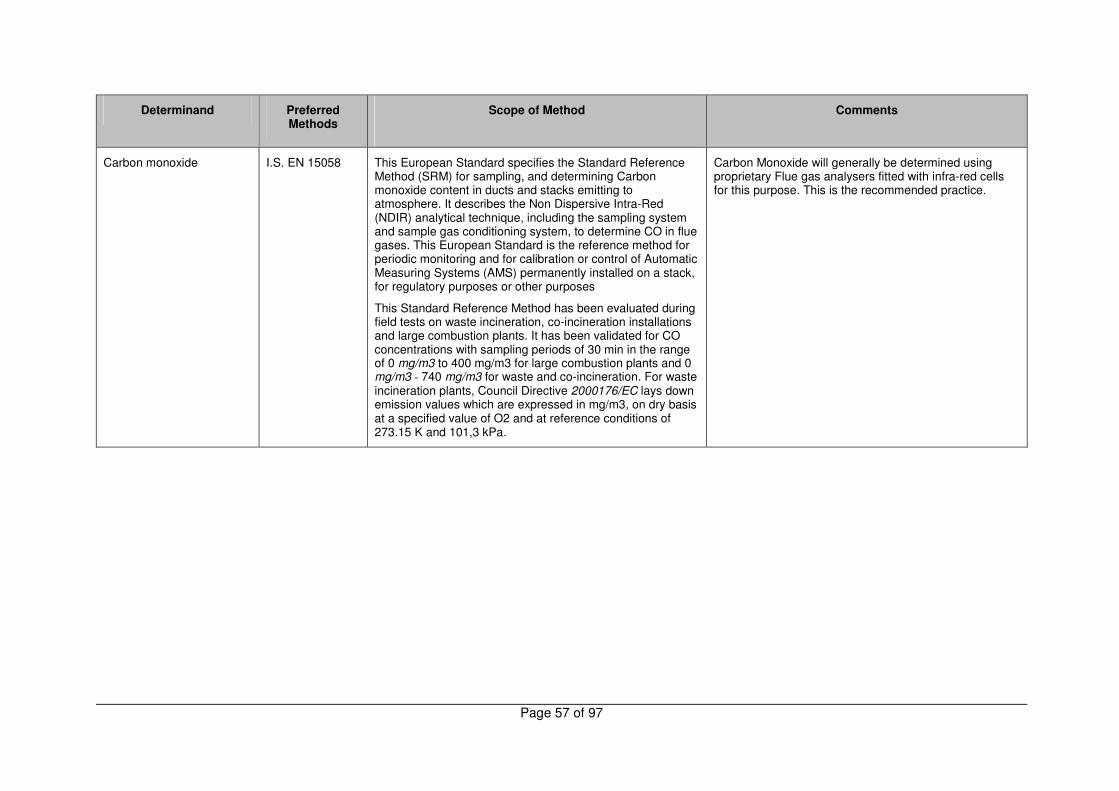
Page 57 of 97
Determinand Preferred Methods
Scope of Method
Comments
Carbon monoxide I.S. EN 15058 This European Standard specifies the Standard Reference Method (SRM) for sampling, and determining Carbon monoxide content in ducts and stacks emitting to atmosphere. It describes the Non Dispersive Intra-Red (NDIR) analytical technique, including the sampling system and sample gas conditioning system, to determine CO in flue gases. This European Standard is the reference method for periodic monitoring and for calibration or control of Automatic Measuring Systems (AMS) permanently installed on a stack, for regulatory purposes or other purposes
This Standard Reference Method has been evaluated during field tests on waste incineration, co-incineration installations and large combustion plants. It has been validated for CO concentrations with sampling periods of 30 min in the range of 0 mg/m3 to 400 mg/m3 for large combustion plants and 0 mg/m3 - 740 mg/m3 for waste and co-incineration. For waste incineration plants, Council Directive 2000176/EC lays down emission values which are expressed in mg/m3, on dry basis at a specified value of O2 and at reference conditions of 273.15 K and 101,3 kPa.
Carbon Monoxide will generally be determined using proprietary Flue gas analysers fitted with infra-red cells for this purpose. This is the recommended practice.

Page 58 of 97
Determinand Preferred Methods
Scope of Method
Comments
Dioxin/Furan I.S. EN 1948 Part 1, 2 and 3
This Standard specifies both method validation and a framework of quality control requirements which have to be fulfilled by any PCDD/PCDF sampling.
The user has the possibility to choose between three different methods:
`Filter/Condenser Method'
`Dilution Method'
`Cooled Probe Method'
Each sampling method is illustrated by some sampling systems described in detail in annex B as examples of proven procedures.
The procedure described in the three parts of EN 1948 : 2006 specifies requirements which shall be met in order to measure the 17 congeners necessary to calculate the total I-TEQ
During comparison measurements on municipal waste incinerators at the level of about 0,1 ng I-TEQ/m3, these three methods have been deemed comparable within the expected range of uncertainty. Validation trials were performed on the flue gas of municipal waste incinerators at the level of about 0,1 ng I-TEQ/m3 and a dust loading of from 1 mg/m3 to 15 mg/m3.
In principle it is not possible to evaluate the accuracy (trueness and precision) of emission measurements. Following the validation trials, the internal and external variability’s were calculated for the process considered and are set out in clause 13 of EN 1948-3 : 1996. This data gives an indication of the variability which has been observed when using this standard and needs to be taken into account when expressing results.
It is strongly recommended that all Dioxin / PCDF analysis for compliance monitoring purposes be undertaken by test houses / laboratories accredited to
ISO 17025 for this work.

Page 59 of 97
Determinand Preferred Methods
Scope of Method
Comments
Formaldehyde (wood product sources)
NCASI Method C1/WP-98.01
There are a number of historical methods for Formaldehyde involving sampling onto treated filters and solid phase cartridges impregnated with reagents which complex the Formaldehyde. Analysis by colorimetry or High Performance Liquid Chromatography (HPLC) is common. These test methods all suffer from a number of disadvantages such as interferences due to impurities in the reagents and it is recommended that Formaldehyde be determined using the NCASI method.
The source gas is drawn through at least two midget impingers, each containing chilled organic free water. Formaldehyde, Methanol, Ketones and Phenols are absorbed by the water.
Methanol and Ketones can be analysed by direct injection into a Gas Chromatograph with FID detection. . Phenols may be analysed by GC, HPLC or determined as Phenol Index colorimetrically. Formaldehyde is determined by colorimetry.
The NCASI method is used for regulatory compliance testing of dryers and press vents at wood products mills in the USA. The method has met USEPA method 301 validation criteria for measuring methanol, phenol and formaldehyde from those sources
This test method has been extensively validated by the Agency. It has been in routine use for a number of years and is currently accredited to ISO 17025.
Gas velocity and temperature
I.S. EN 13284 Part 1
or
ISO9096
The stated scope of each of these two standards is the isokinetic sampling and determination of particulate (Dust) in waste gas emissions
The stated scope of the method does not cover flow and temperature however the measurement of these parameters are an inherent part of the isokinetic routine for the collection of particulate samples. The method is it commonly used for flow and temperature measurement.
Halogens and halides US EPA Method 26 & 26A
This method is applicable for determining emissions of hydrogen halides (HX) [HCl, HBr, and HF] and halogens (X2) [Cl2 and Br2] from stationary sources when specified by the applicable subpart. Sources, such as those controlled by wet scrubbers, that emit acid particulate matter must be sampled using Method 26A.
There is a considerable similarity between method 26/26A and I.S. EN 1911. While the latter is the recommended procedure for determination of the Hydrogen halides this procedure is necessary when evaluation of the Halogen (e.g. Cl2) is required in the presence of ionised species.

Page 60 of 97
Determinand Preferred Methods
Scope of Method
Comments
Hydrochloric acid (gaseous) I.S. EN 1911 part 1, 2, and 3
This European Standard specifies a method for sampling and filtration of gases, in view of their HCl concentration determination.
Subsequent HCl absorption and analysis are described in EN 1911-2 and EN 1911-3 respectively.
The method applies to ducted gaseous streams emitted by waste incinerators, and more generally to waste gases in which HCl concentration may vary between 1 mg/m
3 and 5
000 mg/m3
under normal pressure and temperature conditions (see note).
The method is validated for gaseous streams of dust concentration below 100 mg/m
3, but is not suitable for
measurement of molecular chlorine Cl2 content, (See above)
This standard measures all chlorides which are then analysed and expressed as HCl.. Analysis is by Ion Chromatography.
Extreme care in sample preparation, sampling and clean up is very important otherwise high results can be obtained. Common sources of error include contamination due to the perspiration of monitoring staff, contamination due to sea salt in coastal regions and poor quality reagent water.
Total Acids (expressed as HCl)
Sampling based on IS EN 1911 Part1. Acid concentration (molarity) determined by potentiometric titration
This parameter is used in licences where acid scrubbers are in operation. The procedure is based on potentiometric titration of the acid impinger solution with dilute Sodium Hydroxide. to neutrality The molarity of the impinger (due to dissolution of all acid gases) is calculated and then expressed as an equivalent mass of HCl
Titrations must be carried out using an automated potentiometric titrator for maximum accuracy. The use of pH meter operating in millivoltage mode does not provide sufficient accuracy as samples are generally so dilute that even using differential (dmv / dvol) plots end point detection is difficult.
Back titration to a given pH is not an acceptable approach due to the relative imprecision of pH measurement (typically ± 0.1 pH unit). The use of Ion chromatography with summation of eluted ions as HCl equivalents based on molecular weight is similarly not acceptable.

Page 61 of 97
Determinand Preferred Methods
Scope of Method
Comments
Hydrogen fluoride ISO 15713 This International Standard is applicable to the measurement of the gaseous fluorides that are entrained in gases carried in stacks or ducts. The gaseous fluoride content is expressed as a mass of Hydrogen fluoride in the stack gas.
This International Standard is applicable to all stacks emitting gases with fluoride concentrations of below 200 mg/m3. It can be used for higher concentrations, but then the absorption efficiency of the bubblers should be checked before the results can be regarded as valid. The detection limit of the method is estimated as 0,1 mg m-3, based on a sample volume of 0, 1 m3. All compounds that are volatile at the filtration temperature and produce soluble fluoride compounds upon reaction with water are measured by this method. The method does not measure fluorocarbons. The concentration of fluoride in the adsorbent solution is then measured using an ion selective electrode, Ion Chromatography may also be used. The amount of fluoride measured is then expressed as Hydrogen fluoride by convention, though this may not reflect the chemical nature of the compounds, which are measured.
This procedure bears a strong similarity to I.S. EN 1911. Whereas for HCl the trapping agent is reagent grade water for this standard the impinger solution is 0.1M Sodium Hydroxide. The use of a caustic trapping agent may cause some minor baseline interference at very low Fluoride concentrations when using the Ion Chromatographic procedure however this approach offers lower detection limits (typically ca. 0.1 mg/l) than using Ion selective electrodes whose lower limit of applications is around 0.2 mg/l. It is recommended that laboratories use Ion Chromatography for detection of Fluoride ions.
Where Fluoride and Chloride are required to be determined on the same stack it is not generally necessary to use water / caustic impingers separately. The absorption efficiency of both trapping agents is very similar and there is good correlation between data obtained by use of either matrix however any deviation from the standard should be noted on the test documentation and report.

Page 62 of 97
Determinand Preferred Methods
Scope of Method
Comments
Hydrogen sulphide US EPA method 11
Colorimetric indicator tubes
This method is applicable for the determination of the H2S content of fuel gas streams at petroleum refineries.
A sample is extracted from a source and passed through a series of midget impingers containing a Cadmium sulphate (CdSO4) solution; H2S is absorbed, forming Cadmium sulphide (CdS). The latter compound is then measured by iodometric titration.
Whereas the reference procedure involves offline analysis the use of colorimetric indicator tubes can provide semi-quantitative assay of H2S on-site and may be a useful indicator for process control or assessing concentrations prior to formal sampling.
The Cadmium reagent used in this procedure is harmful and due care must be exercised in its use and disposal of analysis residues.
Colorimetric tubes can suffer from a number of interferences associated with cross sensitivity to compounds such as Sulphur Dioxide and Mercaptans at high concentrations. Refer to the manufacturers guidance for further information on such reactions.
Mercury I.S. EN 13211 This standard specifies a manual reference method for the determination of the mass concentration of mercury in exhaust gases from ducts or chimneys. This European standard is validated for the determination of the mass concentration of total mercury in exhaust gases from the incineration of waste for the concentration range of total mercury from 0,001 mg/m
3 to 0,5 mg/m3).
The method may be applicable for exhaust gases from other sources with the following typical composition:
Particulate
CxHy
HCI
HF
SO2
CO
NOx
CO2
H2O (g)
O2
Temperature
0 mg/m3 to 20 mg/m3
0 mg/m3 to 10 mg/m3
0 mg/m3 to 50 mg/m3
0 mg/m3 to 10 mg/m3
0 mg/m3 to 250 mg/m3
0 mg/m3 to 250 mg/m3
0 mg/m3 to 500 mg/m3
0 to 15 % (vf)
2 % to 25 % (vf) (actual)
8 % to 15 % (vf) (dry, actual)
60°C to 140°C

Page 63 of 97
Determinand Preferred Methods
Scope of Method
Comments
Metals VDI 3868 part 1 (sampling). VDI 2268 parts 1-4 (analysis)
Titles of standards
VDI 3868 Part 1 (1994) Determination of total emission of metals, metalloids, and their compounds - Manual measurement in flowing, emitted gases - Sampling system for particulate and filter-passing matter
VDI 2268 Part 1 (1987) Chemical analysis of particulate matter; determination of Ba, Be, Cd, Co, Cr, Cu, Ni, Pb, Sr, V, Zn in particulate emissions by atomic spectrometric methods
VDI 2268 Part 2 (1990) Chemical analysis of particulate matter; determination of arsenic, antimony and selenium in dust emissions by atomic absorption spectrometry after separation of their volatile hydrides
VDI 2268 Part 3 (1988) Chemical analysis of particulate matter; determination of thallium in particulate emissions by atomic absorption spectrometry
VDI 2268 Part 4 (1990) Chemical analysis of particulate matter; determination of arsenic, antimony and selenium in dust emissions by graphite-furnace atomic absorption spectrometry
These series of German standards offer a broad approach to the problem of the analysis of a wide range of trace metals in particulate and gaseous forms but are now a little dated. They bear strong similarities to I.S. EN 14385 below however the latter has been specifically validated for assessment of emissions from incinerators.
While Part 2 of the VDI series relates to the determination of As, Sb, Se as metal hydrides all of these elements are amenable to detection at very low concentrations using Inductively Coupled Plasma Spectrometry (ICP) or similar analytical procedure.
It is anticipated that sampling / testing laboratories may utilize in-house documented procedures based on IS EN 14385 / VDI standards and these would prove acceptable for the determination of metals.
Some licences incorporate reference to the determination of “Total Heavy Metals”. This term is not readily defined by the International Union of Pure and Applied Chemistry (IUPAC) and many variant definitions exist often relating to specific process or environments however the term is generally regarded as encompassing the commonly occurring transition elements Cd,Cr,Cu,Ni,Pb,Zn as well as trace elements such as Ag, As, Hg, Sb, Se, Sn Mo, V.

Page 64 of 97
Determinand Preferred Methods
Scope of Method
Comments
Metals (As, Cd, Cr, Co, Cu, Mn, Ni, Pb, Sb, TI and V)
I.S. EN 14385 This European Standard specifies a manual reference method for the determination of the mass concentration of specific elements in exhaust gases from hazardous and municipal waste incinerators. The method is applicable to each of the specific elements in the concentration range of 0,005 mg/m3 to 0,5 mg/m . Unless otherwise stated, concentrations are expressed at volumes under dry conditions, normalised to 273.15 K, 101,3 kPa, and Oxygen content with a volume fraction of 11 %.
Specific elements according to this European standard are antimony (Sb), arsenic (As), cadmium (Cd), chromium (Cr), cobalt (Co), copper (Cu), lead (Pb), manganese (Mn), nickel (Ni), thallium (TI), and vanadium (V).
This European Standard is also applicable for exhaust gases from other sources with a flue gas composition, similar to that given in Table 1. The performance characteristics of the method determined for waste incinerators cannot be extrapolated to be used for other types of matrix without any further validation work.
NOTE This European Standard has been validated with the described materials, equipment, sampling and digestion performances etc., followed by analyses with MS and ICP. This does not exclude the use of other types that meet the requirements and proven to be equivalent to the described European Standard.
This European Standard has been validated for the determination of the mass concentration of metals in incineration exhaust gases, within the uncertainties stated in clause 9 of the standard.
If Mercury is to be determined as well, this may be sampled in a side stream arrangement of the sampling train (EN 13211).
The German TA Luft classification system used by the Agency in many air emission licences includes reference to several of the above metals in the Inorganic Particulate Matter Class I – III.
Table 1 - Exhaust Gas Matrix (Waste incineration)
Parameter to be determined
Mass concentration range
Total suspended matter 0 to 20 mg/m3
Total Organic Carbon 0 to 20 mg/m3
HCI 0 to 20 mg/m3
HF 0 to 2 mg/m3
SO2 0 to 100 mg/m3
CO 0 to 250 mg/m3
NOx as NO2 0 to 500 mg/m3
Volume fraction range
CO 3 to 15 % (dry, actual)
H2O (ga) 10 to 35 % (actual)
O2 3 to 17 % (dry, actual)
Temperature 60 to 200 oC
Where this is the case the VDI procedures are recommended for non-incinerator applications and I.S. EN 14385 for incinerator emissions.

Page 65 of 97
Determinand Preferred Methods
Scope of Method
Comments
Nitrogen oxides I.S. EN 14792 This European Standard describes the chemiluminescence method, including the sampling and the gas conditioning system, to determine the NO/NO2/NOx concentrations in flue gases emitted from ducts and stacks at atmosphere. This European standard is the Standard Reference Method (SRM) for periodic monitoring and for calibration or control of Automatic Measuring Systems (AMS) permanently installed on a stack, for regulatory or other purposes such as calibration. .
This SRM has been evaluated during field tests on waste incineration, co-incineration and large combustion installations. It has been validated for sampling periods of 30 min in the range of 0 mg NO2/m
3 to 1 300 mg NO2/m
3 for
large combustion plants and 0 mg NO2/m3 to 400 mg NO2/m
3
for waste incineration, according to emission limit values (ELVs) laid down in the following council Directives.
- Council Directive 2001/80/EC on the limitation of emissions of certain pollutants into the air from large combustion plants;
- Council Directive 2000/76/EC on waste incineration plants.
The ELVs for NO x (NO + NO2) in EU directives are expressed in mg NO2/m
3, on dry basis, at a reference value
for o2 and at the reference conditions (273.15 K and 101,3 kPa).
Nitrogen Oxides will generally be determined using proprietary Flue gas analysers fitted with chemiluminescence cells for this purpose. This is the recommended practice.
Odour
I.S. EN 13725 This European Standard (EN) specifies a rigorous method for the objective determination of the odour concentration of a gaseous sample using dynamic olfactometry with human assessors and the emission rate of odours emanating from point sources, area sources with outward flow and area sources without outward flow. The primary application is to provide a common basis for evaluation of odour emissions in the member states of the European Union.
This European Standard is applicable to the measurement of
This standard provides a method for the objective determination of the odour concentration of a gaseous sample using dynamic olfactometry with human assessors.
It provides a definitive reference but one which is extremely complex and is likely to be employed only in

Page 66 of 97
Determinand Preferred Methods
Scope of Method
Comments
Odour (continued)
odour concentration of pure substances, defined mixtures and undefined mixtures of gaseous odorants in air or nitrogen, using dynamic olfactometry with a panel of human assessors being the sensor. The unit of measurement is the European odour unit per cubic metre: ouE/m
3.
The odour concentration is measured by determining the dilution factor required to reach the detection threshold.
The odour concentration at the detection threshold is by definition 1 ouE/m
3. The odour concentration is then
expressed in terms of multiples of the detection threshold. The range of measurement is typically from 101 ouE/m
3 to
107 ouE/m3 (including pre-dilution).
The field of application of this European Standard includes:
� the measurement of the mass concentration at the detection threshold of pure odorous substances in g/m3;
� the measurement of the odour concentration of mixtures of odorants in ouE/m3;
� the measurement of the emission rate of odorous emissions from point sources and surface sources (with and without an outward flow), including pre-dilution during sampling;
� the sampling of odorants from emissions of high humidity and temperature (up to 200 _C);
� the determination of effectiveness of end-of-pipe devices used to reduce odour emissions.
The characterisation of odour emissions requires detailed measurement of the gas velocity, that shall be performed according to the relevant standards included in the normative references.
This European Standard is not applicable to:
� the measurement of odours potentially released by
circumstances where a more pragmatic approach to the characterisation and assessment of odour nuisance has been unsuccessful.
Odours are often extremely complicated to define involving the impacts of many substances at extremely low concentrations. In some instances (e.g. chemical odours) it may be possible to characterise some of the odour producing substances by sampling onto Charcoal or Thermal desorption tubes for analysis by GCMS as per specific organics however the very low concentrations involved will require large sample volumes. Instruments typically operating with high sample split ratios will require to be re-tuned to obtain maximum sensitivity.

Page 67 of 97
Determinand Preferred Methods
Scope of Method
Comments
Odour (continued)
particles of odorous solids or droplets of odorous fluids suspended in emissions;
� the measuring strategy to be applied in case of variable emission rates;
� the measurement of the relationship between odour stimulus and assessor response above detection threshold;
� direct measurement of hedonic tone (or (un)pleasantness) or direct assessment of potential annoyance;
� field panel methods;
� measurement of recognition thresholds;
� measurement of identification thresholds.
Although the ultimate application of odour measurement is in reducing odour nuisance, the relation between measured thresholds of odour according to this standard and the occurrence of odour nuisance is highly complex.
It is profoundly influenced by the atmospheric processes determining the dispersion of odours, the quality of the odour (hedonic tone) and finally by the receptor characteristics of those exposed to the odour. These characteristics not only vary strongly between individuals, but also in time within one individual. The relation between emissions, dispersion, exposure and annoyance is not within the scope of this European Standard.

Page 68 of 97
Determinand Preferred Methods
Scope of Method
Comments
Organic carbon (Individual gaseous compounds)
Adsorption onto dual bed ATD tubes coupled with adsorption on charcoal as backup. Analysis by ATD / GCMS / Solvent desporption as appropriate
The measurement of organic substances in emissions to air presents perhaps more challenges and options than any other group of parameters in IPPC licences. The methods detailed n this sub-section have been found to provide data of suitable quality for assessment of compliance monitoring.
I.S. EN 13649 provides a general approach to organics as does US EPA Method 18. ASTM Method D6348-03 (not described here) describes the use of FTIR for organics assay while the VDI references are taken from TA Luft and are now somewhat dated They all provide practical means of determining the concentrations of organic species however in the Agency’s view the most practicable approach to the routine measurement of organics is the use of Thermal Desorption tubes coupled with GCMS assay.
The use of selective polymeric resins such as Tenax ™/ Spherocarb ™ or similar highly retentive material allows considerable scope and flexibility for the assessment of organic emissions. Tubes can be packed with multiple sorbents in series to ensure quantitative trapping. The gas is drawn through the tube using small constant flow sample pumps at a flow rate of 100 -200ml/min. for 30 minutes.
For some polar organics substances such as Methanol and Ethanol the use of Thermal Desorption affords quantitative recovery however such substances are hydrophilic and can be readily trapped in water and determined using GC-FID
The typical range covered by this type of procedure is limited by the requirement to prepare standards by direct injection of pure compound mixture. The mass on tube for the INAB accredited procedure utilised by the Agency’s Cork laboratory is from 1 – 170µg for Benzene up to 8 – 1720 µg fro m+p-Xylene.
The procedure determines 20 commonly occurring aromatic, halocarbon and oxygenated organics but the basic approach can be tailored to suit individual applications. Identification and quantitation is by GCMS using a 5 standard calibration.
Though more complex instrumentation is required this approach has many advantages over the methods described below and is the Agency’s preferred procedure for organics analysis. Charcoal tubes sampled simultaneously are used to quantify over-range values or to facilitate quantitation of substances not contained in the GCMS standard mix.

Page 69 of 97
Determinand Preferred Methods
Scope of Method
Comments
Organic carbon (Individual gaseous compounds)
I.S. EN 13649 This European Standard specifies procedures for the sampling onto activated carbon, the preparation and the analysis of samples of volatile organic components such as those arising from solvent using processes. It can be used as a reference method.
NOTE See Council Directive 1999/13/EEC.
The results obtained using this Standard are expressed as the mass concentration (mg/m
3) of the individual gaseous
organic components. This Standard is suitable for use in the range of about 0,5 mg/m
3 to 2000 mg/m
3.
I.S. EN 13649 is a general method for the determination of the mass concentration of individual gaseous organic compounds by adsorption onto charcoal and solvent desorption / GC-FID assay. The most commonly utilised solvent is Carbon Disulphide (CS2) however this is an unpleasant material to handle and does not desorb some polar substances such as Methanol, Ethanol with more than 60% efficiency.
Alternative desorption mixtures may be used to improve recovery however to utilise the method for a range of target compounds it will be necessary to determine the recovery efficiency for each target substance by extensive method validation.
The procedure recommends the use of GC-FID analysis however this procedure relies solely on retention time for compound identification and even using GC columns of differing polarity several common substance groups may co-elute rendering identification difficult. It is therefore recommended that this approach be utilised as a backup to alternative procedures (such as Thermal Desorption) which facilitate the use of direct GCMS assay for both quantitation and identification.

Page 70 of 97
Determinand Preferred Methods
Scope of Method
Comments
Organic carbon (Individual gaseous compounds)
US EPA Method 18
This method is designed to measure gaseous organics emitted from an industrial source. While designed for ppm level sources, some detectors are quite capable of detecting compounds at ambient levels, e.g., ECD, ELCD, and helium ionization detectors. Some other types of detectors are evolving such that the sensitivity and applicability may well be in the ppb range in only a few years.
This method will not determine compounds that (1) are polymeric (high molecular weight), (2) can polymerize before analysis, or (3) have very low vapour pressures at stack or instrument conditions.
The lower range of this method is determined by the sampling system; adsorbents may be used to concentrate the sample, thus lowering the limit of detection below the 1 part per million (ppm) typically achievable with direct interface or bag sampling. The upper limit is governed by GC detector saturation or column overloading; the upper range can be extended by dilution of sample with an inert gas or by using smaller volume gas sampling loops. The upper limit can also be governed by condensation of higher boiling compounds.
NOTE: This method is not inclusive with respect to specifications (e.g., equipment and supplies) and procedures (e.g., sampling and analytical) essential to its performance. Some material is incorporated by reference from other methods in this part. Therefore, to obtain reliable results, persons using this method should have a thorough knowledge of at least the following additional USEPA test methods: Method 1, Method 2, Method 3.
Although included in this sub-section US EPA Method 18 is similarly a generalised approach to organic compounds in stack emissions. It is recommended that the alternative test methods outlined above be used in preference to this procedure.
Organic carbon (Individual gaseous compounds)
VDI 3481 parts 2, 3 and 6.
Titles of standards
Part 2 - Gaseous emission measurement - Determination of gaseous organic carbon in waste gases - Adsorption on silica gel
Part 3 Gaseous emission measurement - Determination of volatile organic compounds, especially solvents, flame ionization detector (FID)
Part 6 Gaseous emission measurement - Choice and application of methods of measuring total gaseous organic carbon
These methods are included in this sub-section to provide operators with alternatives to the preferred options above e.g. where instrumentation is not available. They should be carefully reviewed and assessed for their suitability to the process being monitored before being utilised as an alternative method and their usage agreed with the Agency prior to use.

Page 71 of 97
Determinand Preferred Methods
Scope of Method
Comments
Organic carbon (Individual gaseous compounds)
VDI 2457 parts 2-7
Titles of standards
Part 2 Gaseous emission measurement - Gas chromatographic determination of organic compounds - Sampling by absorption in a solvent (2-(2-methoxyethoxy)ethanol, methyldiglycol) at low temperature
Part 7 Gaseous emission measurement - Gas chromatographic determination of acetic acid esters with boiling points up to 90 °C

Page 72 of 97
Determinand Preferred Methods
Scope of Method
Comments
Organic carbon (Total gaseous at low concentrations)
Condensable Volatile Organic Compounds (CVOCs)
I.S. EN 12619 This European Standard specifies a set of minimum performance requirements for an instrument using flame ionization detection, together with procedures for its calibration and operation, for the measurement of the mass concentration of total gaseous organic carbon (TOC) in stationary source combustion emissions.
This European Standard is suitable for the measurement of low level gaseous or vapour phase TOC emissions such as those from municipal waste incinerators and hazardous waste incinerators.
NOTE See Council Directive 89/369/EEC which is under revision and Council Directive 94/67/EC.
This standard is not recommended for performing measurements on solvent using processes processes and I.S EN 13526 should be used for such systems.. Minimum operational requirements for long term emissions monitoring are suggested in annex A of the standard. It is likely that these will be modified by subsequent European Standards. The results obtained using this standard are expressed in milligrams per cubic metre as total
carbon (mg/m3). This standard is suitable for use in the range
0 mg/m3 to 20 mg/m
3.
The method specified in this European Standard can be used as a reference method or, with suitable minimum operational requirements, for continuous monitoring. It can also be used for the calibration of automated measuring systems. An indication of the uncertainty of the measurement is shown in annex B.
Defines a set of minimum performance requirements for an instrument using flame ionization detection, together with procedures for its operation and calibration, for the measurement of the mass concentration of total gaseous organic carbon (TOC) in stationary source combustion emissions.
Appendix 2 of the Agency’s BATNEEC Guidance Note for Board Manufacture (1996) details a procedure for assessment of Condensable VOCs involving determination of the TOC of impingers plus Chemical Oxygen demand of vapour adsorbed onto a Silica Gel trap and quartz filter. The procedure provides insufficient detail regarding the analysis of the Silica gel and filter to facilitate robust calculation of Total CVOC. It is therefore recommended that where assessment of water soluble organic compounds (as CVOC) is required that vapours are trapped in impingers containing reagent grade water and the non-purgeable organic carbon determined using a procedure based on EN ISO 1484. This approach provides a direct measurement of organic C.
Organic carbon (Total gaseous from solvent processes)
I.S. EN 13526 This European Standard specifies a set of minimum performance requirements for an instrument using flame ionisation detections, together with procedures for its calibration and operation, for the measurement of the mass concentration of total gaseous organic carbon (TOC) in flue gases.
Specifies a set of minimum performance requirements for an instrument using flame ionisation detection.

Page 73 of 97
Determinand Preferred Methods
Scope of Method
Comments
Oxygen I.S. EN 14789 This European Standard describes the paramagnetic method, including the sampling and the gas conditioning system, to determine the oxygen concentrations in flue gases emitted to the atmosphere from dusts and stacks.
This European Standard is the Standard Reference Method (SRM) for periodic monitoring and for the calibration or control of Automatic Measuring Systems (AMS) permanently installed on a stack, for regulatory purposes or other purposes. To be used as the SRM, the user shall demonstrate that the performance characteristics of the method are better than the performance criteria defined in this European Standard and that the overall uncertainty of the method is less + 6,0 % of the measured concentration.
NOTE When paramagnetism is the measurement principle used for AMS, reference should be made to EN 14181 and other relevant standards provided by CEN/TC 264.
The Standard Reference Method has been evaluated during field tests on waste incineration, co-incineration and large combustion installations. It has validated for sampling periods of 30 min in the range: 5 % to 26 %. Oxygen concentration values, expressed in % volume, are used in order to allow emission measurement of pollutants to be standardised to the reference O2 concentration and dry gas condition required by the following Council Directives:
- Council Directive 2001/80/EC on the limitation of emissions of certain pollutants into the air from large combustion plants;
- Council Directive 2000/76/EC on waste incineration plants.
Oxygen will generally be determined using proprietary Flue gas analysers fitted with Oxygen sensitive sensors for this purpose. This is the recommended practice.
The paramagnetic technique is not well-suited to measurement at the low O2 concentrations typical of oil and gas-fired boiler plant. Both the zirconia and the electrochemical cell are validated Alternative Reference Methods for EN14789 and should be included in the Index of Preferred Methods.
The use of handheld wet chemical absorbing systems can provide a useful process tool for the measurement of Oxygen and Carbon Dioxide in combustion systems but should not be used as the primary method of determination for either parameter.

Page 74 of 97
Determinand Preferred Methods
Scope of Method
Comments
PAH's ISO 11338 part 1 and 2
This International Standard describes methods for the determination of the mass concentration of PAH in flue gas emissions from stationary sources such as aluminium smelters, coke works, waste incinerators, power stations, and industrial and domestic combustion appliances. It does not deal with the sampling of fugitive releases of PAHs.
This part of ISO 11338 describes three sampling methods, which are here regarded as of equivalent value, and specifies the minimum requirements for effective PAH sampling.
NOTE Methods for sample preparation, clean-up and analysis are described in ISO 11338-2 and should be combined with one of the sampling methods described in this part of ISO 11338 to complete the whole measurement procedure.
The three sampling methods described in this part of ISO 11338 are A) the dilution method, B) the heated filter/condenser/adsorber method and C) the cooled probe/adsorber method. All three methods are based on representative isokinetic sampling as the PAHs are commonly associated with particles in flue gas. The user of the standard has the option to choose between these three methods depending on the measurement application.
Information is provided to assist in the choice of the appropriate sampling method for the application under consideration.
Polycyclic aromatic hydrocarbons (PAH) are a group of aromatic hydrocarbons, some members of which are probable and others possible human carcinogens. Human exposure to PAH can occur via food, soil, water, air and skin contact with materials containing PAH. While PAH are formed in natural processes (e.g. forest fires), man-made atmospheric emissions of these compounds originate from the combustion of coal, gas, wood, and oil, from a range of industrial processes such as coke production, aluminium melting and from vehicles.
The quantification of atmospheric releases of PAHs from stationary sources is an important part of the environmental impact assessment of certain industrial processes.
Due to the complexity of sampling and analysis procedures for these substances it is strongly recommended that operators monitoring for these parameters use third parties accredited to ISO 17025 for the sampling / analysis of PAHs.

Page 75 of 97
Determinand Preferred Methods
Scope of Method
Comments
Particle size fractionation US EPA method 201A
This method applies to the in-stack measurement of particulate matter (PM) emissions equal to or less than an aerodynamic diameter of nominally 10 µm (PM10 )from stationary sources.
The EPA recognizes that condensible emissions not collected by an in-stack method are also PM10, and that emissions that contribute to ambient PM10 levels are the sum of condensible emissions and emissions measured by an in-stack PM10 method, such as Method 201A.
Therefore, for establishing source contributions to ambient levels of PM10 , such as for emission inventory purposes, EPA suggests that source PM10 measurement include both in-stack PM10 and condensible emissions.
Condensible emissions may be measured by an aqueous impinger analysis in combination with this method.
New standards are being developed by ISO in co-operation with CEN. These standards will be published in 2008 and comprises a standard for below 50 mg/m3 using impactors of different design and performance characteristic to M201a. The second standard is for above 50 mg/m3 and uses cyclones similar to those in M201a.
Condensible VOCs may be determined as non-purgeable organic carbon using a procedure based on EN ISO 1484

Page 76 of 97
Determinand Preferred Methods
Scope of Method
Comments
Particulate ISO 9096 This standard is similar to EN 13284-1 but with a higher range of 20 to 1000 mg/m3.
A representative, integrated sample is extracted from the flue gas and particulate matter entrained in the gas sample is separated by a filter. The pre-weighed filter is subsequently dried and weighed. A relative increase in the mass is attributed to the collection of particulate matter on the filter.
To meet the specifications of this International Standard, the particulate sample must be weighed to a specified level of accuracy. This level of accuracy may be achieved by:
1) exercising extreme care in weighing, as per the procedures of this standard;
2) extending the sampling time at conventional sampling rates;
3) sampling at higher rates for conventional sampling times (high-volume sampling);
4) all dust upstream of the filter must be recovered.
Gravimetric assay of dust filters is straightforward however it is recommended that samples be analysed by the test house engaged to sample as the logistics of drying, repacking, equilibrating and transporting filters can prove difficult to coordinate. Care should be taken in the analysis of filters where the particulates may volatilise at temperatures of 100- 105°C. In these cases samples should be equilibrated to constant weight over a suitable desiccant.
For quantitation a 4 decimal place balance is generally suitable
Particulate (low range) I.S. EN 13284 Part 1
This European Standard specifies a reference method for the measurement of low dust concentration in ducted gaseous streams in the concentrations below 50 mg/m3 standard conditions. This method has been validated with special emphasis around 5 mg/m3 on an average half hour sampling time.
The European Standard is primarily developed and validated for gaseous streams emitted by waste incinerators.
More generally, it may be applied to gases emitted from stationary sources, and to higher concentrations.
If the gases contain unstable, reactive or semi-volatile substances, the measurement depend on the sampling and filter treatment conditions.
This analysis is extremely challenging. A number of difficulties exist with the robustness of sampling ad measurement procedures. It is recommended that all samples be analysed by the test house engaged to sample. Care should be taken in the analysis of filters where the particulates may volatilise at temperatures of 100- 105°C. In these cases samples should be equilibrated to constant weight over a desiccant.
Accurate quantitation of particulate mater a <1 mg/m3 a 5
requires lengthy sampling times / volumes. Laboratory analysis requires the use of a 5 decimal place balance and specialised laboratory environments.
Further guidance is being developed within the UK and this section will be updated when this is available.

Page 77 of 97
Determinand Preferred Methods
Scope of Method
Comments
PCB's I.S. EN 1948 Part 1, 2 and 3
Refer to scope for Dioxins
A revised standard (soon to be published) has a Part 4 section that deals specifically with PCB’s.
While PCBs can be determined in the same trap as Dioxins / PCDFs it is recommended that separate traps be used for their assay to ensure maximum recovery.

Page 78 of 97
Determinand Preferred Methods
Scope of Method
Comments
Phenols & Cresols I.S. EN 13649 (sampling)
NIOSH or OSHA methods for analysis
Impinger sampling as per IS EN 1911 Part 1 followed by colorimetry (Phenol Index), HPLC, or GC analysis of individual compounds
This European Standard specifies procedures for the sampling onto activated carbon, the preparation and the analysis of samples of volatile organic components such as those arising from solvent using processes. It can be used as a reference method.
The results obtained using this Standard are expressed as the mass concentration (mg/m3) of the individual gaseous organic components. This Standard is suitable for use in the range of about 0,5 mg/m
3 to 2000 mg/m
3.
The NIOSH Manual of Analytical Methods lists several test methods for determination of Phenols / Cresols. For individual substances such as follow the recommended approach for the relevant compound
IS. EN 1911 uses aqueous impingers for the trapping of acid gases however the extremely hydrophilic nature of Phenols / Cresols means that they can also be trapped in impingers for determination as Phenol Index (Colorimetry), or individual phenols by HPLC or GC
I.S. EN 13649 is not specific to phenols/Cresols, but is a general method for the determination of the mass concentration of individual gaseous organic compounds by adsorption onto charcoal and solvent desorption / GC-FID assay. If used for the determination of Phenols or Cresols it will be necessary to evaluate the efficiency of sampling / recovery of target compounds prior to its use
Select the NIOSH (or OSHA) analytical method that is specific to the pollutant of interest. It should be consistent with the sample trap and provide the necessary performance in terms of method range and uncertainty.
This approach provides a practical alternative to tube sampling particularly where the analysis can be combined with the determination of other water soluble organics e.g. Formaldehyde

Page 79 of 97
Determinand Preferred Methods
Scope of Method
Comments
Sulphur dioxide I.S. EN 14791 This European Standard describes a manual method for sampling and determining SO2 content in ducts and stacks emitting to the atmosphere by two analytical methods: Ion chromatography and Thorin method.
This European Standard is the Standard Reference Method (SRM) for periodic monitoring and for calibration or control of Automatic Measuring Systems (AMS) permanently installed on a stack, for regulatory purposes or other purposes
This Standard Reference Method has been evaluated during field tests on waste incineration, co-incineration and large combustion installations. It has been validated for sampling periods of 30 mins in the range of (0,5 to 2 000) ms/m
3 SO2
for Ion Chromatography variant and 5 mg/m3 to 2 000 mg/m
3
SO2 for the Thorin method according to emission limit values laid down in the following Council Directives.
- Council Directive 2001/80/EC on the limitation of emissions of certain pollutants into the air from large combustion plants;
- Council Directive 2000/76/EC on waste incineration plants.
Sulphur Dioxide will generally be determined in-situ using proprietary Flue gas analysers fitted with infra-red cells for this purpose. This is the recommended practice.
The reference method uses off-line laboratory analysis and is not suited as a process control tool. The Thorin titration method is less common with the advent of Ion Chromatography. In this process Sulphur Dioxide is measured as Sulphate ion
Validation of an alternative method
I.S. CEN TS 14793
The purpose of this technical specification is to specify a validation procedure to show if an Alternative Method (AM) can be used as an alternative to the Standard Reference Method (SRM), both implemented to determine the same measurand. This document has been drawn up for laboratories working in air pollution measurements (and consequently examples taken from this sector are included in the appendices).
In particular, this Technical Specification provides the statistical tools and different criteria to evaluate the alternative method; this does not release the person responsible for this validation from bearing technical and analytical judgement on the evaluation of the different
The purpose of including this section is to highlight the approach required to developing and validating an entirely new procedure for air emissions monitoring.
The procedure is both lengthy and complex but requires that both sampling and laboratory measurements be validated extensively to determine the range of applicability, detection limits, interferences and overall measurement uncertainty.

Page 80 of 97
Determinand Preferred Methods
Scope of Method
Comments
Validation of an alternative method (continued)
criteria.
Three steps are described in the validation procedure:
� description of the AM and setting of the field of equivalence (range and type of gas matrix);
� determination of the performance characteristics of the AM and calculation of the overall uncertainty where appropriate and check of compliance of the maximum overall uncertainty allowed for the SRM;
� check of repeatability and lack of systematic deviation of the AM in the field in comparison with the SRM for the type of matrix defined in the field of equivalence.
NOTE Some parts of the second step of the validation of the alternative method should be performed by a recognised test-house.
If the AM fulfils the requirement of the procedure, then the laboratory that carried out the whole validation process is allowed to use it as a SRM in the field application where the equivalence has been demonstrated.
However, if the validation process involves at least 4 different accredited laboratories performing simultaneously parallel measurements in the field, and if the AM passes with success all the tests of the procedure, then this method could be proposed to CEN, who can decide to consider this AM as a new reference method (ARM).
The use of this procedure implies that a reference method has been defined by the regulator or in a contract and has been validated.
This Technical Specification only considers the case of linear quantitative methods.

Page 81 of 97
Determinand Preferred Methods
Scope of Method
Comments
Water vapour I.S. EN 14790 This European Standard describes the condensation/adsorption technique, including the sampling system, to determine the water vapour concentration in the flue gases emitting to atmosphere from ducts and stacks.
This European Standard as the Standard Reference Method (SRM) is used for periodic monitoring and for calibration or control of Automatic Measuring Systems (AMS) permanently installed on a stack, for regulatory purposes or other purposes.
The determination of water vapour is mainly necessary for:
- regulatory purposes, to express the concentration at standard conditions (on dry gas);
- adjust the flow rate for isokinetic sampling, when a dry gas flow rate metering device is used.
For both applications, the quantity to be measured is the amount of water present in the gas phase (vapour), which does not include water droplets.
This European Standard is applicable in the range from 4 % to 40 % relative humidity and for water vapour concentration from 29 g/m3 to 250 g/m3 as a wet gas, although for a given temperature the upper limit of the method is related to the maximum pressure of water in air or in the gas.
This European Standard has been evaluated during field tests on waste incineration, co-incineration and large combustion installations. It has been validated for sampling periods of 30 min in the concentration range of 7 % to 26 % volume.
In this European Standard all the concentrations are expressed in normal conditions (273.15 K and 101,3 kPa).
NOTE For saturated conditions the condensation/adsorption method is not applicable. Some guidance is given in this European Standard to deal with flue gas when droplets are present.
Assessment is by volumetric / gravimetric analysis using impingers / Silica gel traps.

AIR EMISSION MONITORING GUIDANCE NOTE #2
Page 82 of 97
Appendix 2 – Stack emission monitoring - Audit checklist
The checklist is designed to assess the stack emissions monitoring practices at a licensed facility against best practice as described in this Guidance Note. The list is not based on a particular standard e.g. ISO 17025 or MCERTS although many elements are common. It is a tool that may be used in a variety of audit situations:
� Agency audit of licensee
� Licensee audit of monitoring contractor
� Contractor’s internal audit
The entire checklist may be used as a vertical audit that examines all the contributing elements to a single measurement result. Note that not every criterion will be applicable to every monitoring scenario and some criteria overlap with others. Alternatively, a section of the checklist can be used as a horizontal audit to examine one element of the monitoring operation and its contribution to a number of measurement results. Each section of the list references the chapter of that guidance which deals with the criteria being assessed.
Criteria Assessment
(poor/average/good)
Justification
(suggested improvement)
General sampling and measurement – 3.1.1
Technique employed is suited to the pollutant and the application
Sample/measurement system is leak tight
Mitigation against sample loss or interference
Supporting measurements simultaneous with pollutant determination
General – Sample collection - 3.1.2
Measurement of sample volume and correction to standard conditions
Particles sampled isokinetically (and droplets where necessary)
Sample handling, (i.e. recovery, labelling, storage, transport and chain of custody)
General – Measurement using portable analyser - 3.1.3
Range appropriate to pollutant concentration

Page 83 of 97
Criteria Assessment
(poor/average/good)
Justification
(suggested improvement)
Calibration before and after measurement
Analyser free from bias/interference from other stack gases
Analyser suited to working environment (e.g. heat, dust, rain etc)
Units, standardisation and reference conditions - 3.2, 3.3
Results presented in the units specified (mass conc. Mass flow, vol. flow)
Proper correction of data for temperature and pressure
Proper data correction to reference conditions
Monitoring plan and other factors - 4
Use of site review
Use of site specific protocol
The monitoring location allows representative sampling/measurement of the gases that are released to atmosphere (cf: EPA Air Guidance note #1)
The timing and duration of the monitoring event is representative of peak emissions (or otherwise agreed with the Agency)
Use of Emission Indicating Parameters in monitoring report
Provision of AMS data in monitoring report
Provision of measurement uncertainty information
Provision of measurement traceability information

Page 84 of 97
Criteria Assessment
(poor/average/good)
Justification
(suggested improvement)
Is the monitoring conducted in the manner prescribed in the licence (or otherwise agreed with the Agency)
Pollutant specific considerations - 5
This section of the checklist can be used to assess how the monitoring practices deal with the issues that arise when monitoring the following pollutants. Refer to the listed subsection in chapter 5 for a discussion of the issues.
Total particulate 5.1
Combustion gases 5.2
Inorganic gases 5.3
Metals and metal species 5.4
Organic gases (total) 5.5
Organic gases (speciated) 5.6
Formaldehyde 5.7
Dioxins 5.8
Flow rate 5.9
Reference quantities 5.10
Colour indicating tubes 5.11
The Equipment - 6
Equipment management. Labelling and recording of usage. Calibration and maintenance, procedures, records and scheduling.
Equipment meets the design specification of the standard method.
Adequacy of calibration methods in terms of frequency and traceability
Is the equipment certified to MCERTS, TUV, etc, (where available)
If not certified, how does equipment characteristics compare with certification criteria
The Person - 7

Page 85 of 97
Criteria Assessment
(poor/average/good)
Justification
(suggested improvement)
A system exists that defines staff roles and competency.
Senior staff (team leader) sign off on site review, site specific protocol, and monitoring reports
Training systems include individual training plans, records and logs of site experience.
The Organisation - 8
Quality management system in place
Scope of accreditation (where applicable). Field and/or laboratory
Use of documentation
• Site review
• Risk assessment
• Site specific protocol
Participation in proficiency testing schemes
Standard methods - 9
Standard method stipulated in licence is employed or an Agency agreed method has been selected from the hierarchy that is suitable to the application.
Where there are deviations from the standard method, are they documented, technically justified and validated.
Are method modifications and deviations validated in accordance with CEN/TS 14793:2004
The Monitoring report - 10
The reporting process fulfils the requirements of the licence, (e.g. submission

Page 86 of 97
Criteria Assessment
(poor/average/good)
Justification
(suggested improvement)
deadline, notification of non-compliant results, retention of data and on-site availability of data to the public, etc)
Content of the monitoring report (10.2)
Data rounding and Limit of Detection (10.3)
Good quality- assurance practices used in the generation of report (10.4)

AIR EMISSION MONITORING GUIDANCE NOTE #2
Page 87 of 97
Appendix 3 – Calculations Calculations have been provided curtsey of the Source Testing Association www.s-t-a.org
Calculation of concentrations and mass emissions
To calculate a concentration the mass of the substance collected during sampling is divided by the volume of stack gas sampled.
1. Concentration = mass of substance / sample volume
To convert a concentration to a mass emission it is necessary to know the discharge of gas from the stack.
2. Volume discharge (m3s-1) = velocity of gas (ms-1) x cross-sectional area of stack (m2)
3. Mass emission (e.g. kg.hour-1) = concentration (mg.m-3) x volume discharge (m3.s-1) 10-6 x 3600
The calculation is only valid when the concentration and volume flow terms are in same units of temperature, pressure, moisture content and reference oxygen. To avoid mistakes, it is advisable that data management procedures ensure that the two terms (volume flow and concentration) are available in either of the following formats; (1) fully corrected to reference conditions, or (2) at stack conditions.
Conversion of concentration units (ppm to mg.m-3)
To convert ppm to mg.m-3 the following equation is required:
4. Concentration (mg.m-3) = {concentration (ppm) x molecular weight (g)} / Molar volume(l)
The molar volume is the volume occupied by one-gram mole of a gas at a specific temperature and pressure. The temperature and pressure that concentrations are usually reported at is 273.15K and 101.325 KPa. Under these conditions the molar volume is equal to 22.41 litres.
Temperature and pressure corrections
To convert the concentration as measured at a temperature of T K to the concentration at 273.15 K, multiply by Ft where
5. Ft = T/273.15
To convert the concentration as measured at a pressure of P kPa to the concentration at 101.325 kPa, multiply by Fp where
6. Fp = 101.325/P
For concentration measurements, P and T will be the pressure and temperature at the point where the sample volume is metered. Note that the two equations above should only be used to convert mass concentration (e.g. mg.m-3) and not for volume concentration (e.g. ppm).
When volume flow data is corrected to for temperature and pressure use the reciprocal equations.

Page 88 of 97
Moisture and oxygen corrections
Emissions of stack gases are usually expressed on a dry gas basis so that variation in the moisture of stack gas does not affect the assessment of the emissions.
To convert a concentration from wet gas to dry gas the following is used:
7. Dry gas concentration = Wet gas concentration x {100 /(100 – H2O%)}
To convert a concentration “as measured” to a concentration at reference oxygen level, multiply the concentration by Fo, the correction factor for oxygen, given by:
8. Fo = { 20.9 – O2% reference } / {20.9 – O2% measured }
Note that when using equation 8 the measured oxygen value should be expressed on a dry gas basis. In situations where the measurement technique has provided oxygen data on a wet basis then the data must be converted to a dry basis using equation 7.
Use the reciprocal equations when volume flow data needs to be corrected for moisture and reference oxygen.
Determining the Isokinetic ratio
In order to perform isokinetic sampling it is necessary to calculate the required sampling flow rate to ensure that the velocity of the gas entering the nozzle is the same as the velocity of the stack gas at the sampling plane. This takes into account the velocity of the gas in the stack at the sampling point and the effective diameter of the sampling nozzle.
9. Sampling flow rate = area of nozzle x velocity of gas entering nozzle
By comparing the velocity of the gas at the nozzle with the velocity of the stack gas at the sampling plane the isokinetic ratio is determined.
10. Isokinetic ratio (%) = { velocity at the nozzle x 100 } / velocity of stack gas
It is also possible to check for isokinetic sampling compliance by comparing the required sampling flow rate to the actual sampling flow rate performed during the monitoring.
11. Isokinetic ratio (%) = { actual sampling flow rate x 100 } / required sampling flow rate
I.S. EN 13284-1:2001 for the determination of low range concentration of dust states that, if the mean actual isokinetic ratio during the sampling at the sampling plane differs by more than -5 to +15%, the measurement is not valid.
Note: the notation mg.m-3
is the same as mg/m3, either notation is equally acceptable to the Agency.

Page 89 of 97
Appendix 4 – Site review (reconnaissance visit)
At each stage of the site review, health and safety should be considered and the risk assessment completed.
Factors that should be included in a site review are:
Site information
� Address and contact information;
� General information about the process;
� Scope of work;
Process conditions
� Process characteristics (material balance, process-flow diagrams, feedstock details and the like);
� Expected emissions (concentration or mass);
� Expected process variations;
� Site instrumentation relevant to the monitoring process;
� Emission control equipment (type, operating mode, instrumentation, control arrangements);
Sampling location
� Access to the stack;
� Adequate work area at the sampling positions;
� Availability of required utilities (electrical, lighting, water);
� Sample ports (accessibility, correct size, sufficient number, properly located);
� The stack dimensions at the sampling location;
� A pitot tube traverse of the velocity profile;
� Temperature and moisture of the stack gas;
� Diagram of the sampling point locations and stack geometry;
� Site restrictions on using equipment, for example intrinsically safe areas;
� Physical and chemical restrictions to using equipment;
� Chemical composition of stack gas;
� Determine appropriate monitoring equipment for the application.

Page 90 of 97
Appendix 5 – Template, Site specific protocol
The following is an example of a suitable site specific protocol xiv
The following details should be addressed in a site-specific protocol:
� The site name, address and licensee contact;
� The planned date of the measurement campaign;
� The names of sampling team members, their competency and specific responsibility;
� The type of process;
� A description of the site;
� The identity of the installations to be measured;
� The operational/ feed details, for example, continuous, batch process;
� The duration of any batch processes;
� For non-continuous processes, the part of the process when sampling will take place;
� Any unusual occurrences that take place during the process;
� The process details that need to be collected over the monitoring period;
� The emission-limit values;
� Expected emission values;
� The substances to be monitored at each installation;
� The reference conditions for reporting concentrations;
� The measurement method for each substance;
� The organisation’s technical procedure reference covering implementation of the above method;
� The overall uncertainty of the technical procedure;
� Any modifications to the technical procedure, with justifications and any resulting changes to the uncertainties;
� The equipment used for each substance monitored;
� The sampling duration and number of samples for each measurement, including blanks;
� For manual methods, the proposed sample flow-rate, volume and minimum sampling times;
� For instrumental methods, the proposed span-gas concentration;
� The measurement concentration range and lower detection limit;
� A description of the location of the sampling plane for each release point;
� For each sampling plane, a description of the type of sampling port;
� For each sampling plane, a summary of the number, arrangement and orientation of the sample line(s), and the number of sampling points per line;

Page 91 of 97
� For each sampling plane, a summary of compliance with CEN standards;
� For manual methods requiring a separate chemical analysis stage, details of the analytical method, the laboratory carrying out the analysis, chain-of-custody details, allowable time for transit to the laboratory, storage conditions and archiving requirements;
� The procedure for recording monitoring data;
� The method to be followed for correction of results to standard conditions;
� The report format, the person who will be writing the report and the person who will be checking the report;
� The procedure for checking data quality;
� The date the results report is due to be issued;
� The reference number and date of the on-site health and safety risk assessment the team carried out;
� The reference number of the use of hazardous chemicals risk assessments for each measurement method;
� Any site-specific safety requirements, for example, local safety induction course, intrinsically safe site;
� Any other relevant health and safety requirements.

Page 92 of 97
Appendix 6 - Work file
The work file should contain the following
� Site-specific protocol;
� Site review;
� Risk assessment;
� Equipment checklist, including reference to equipment history file;
� Volume of reagents and amount of sample media required;
� Forms used by the site operator;
� Site calculation and data sheets;
� Record of process conditions at time of monitoring;
� Record of deviations from the approved site protocol.
� Chain of Custody documentation

Page 93 of 97
Appendix 7 - Monitoring records
Monitoring records should include:
� The date;
� The names of the monitoring team members making the records;
� The measurement procedure used;
� The identification of the equipment;
� The sampling location (including diagrams as necessary);
� Environmental conditions, for example, atmospheric pressure;
� Details of measurement start and finish times;
� For manual methods, all relevant details of sampling, for example, dry gas meter readings, solution volumes, pressure and temperature readings;
� For manual methods, the sample details, for example, sample bottle or sorbent tube identification label;
� For instrumental methods, the zero and span gas verification results;
� For instrumental methods, the output or indicated readings of the analyser.

Page 94 of 97
Appendix 8, - Stack emission monitoring report
Submission of reports
Monitoring returns for the assessment of compliance with limit values should be submitted with a cover letter in the format specified below. The letter should include the following information referenced at the top of the page:
1. The IPPC licence Register No.
2. The company name as per the licence application.
3. The reporting period.
4. Required submission date.
5. Report name as listed in the Schedule on “Recording and Reporting to the Agency” to the IPPC licence (Reg No. «Reg_No»).
In a situation where a number of reports are being submitted together the name of each report should be listed on the cover letter. If there were non-compliances in the reporting period, the following details are required:
1. Date.
2. Parameter.
3. Emission point reference no.
4. Number of non compliant measurements versus number of measurements during the reporting period.
5. Maximum exceedence versus licence limit.
6. Cause.
7. Corrective action.
Content of reports
The following is an example of the information that should be included in a monitoring report.
A stack-emission monitoring report should include the following information on each page:
� A unique reference in the following format:
� Licence register number;
� Licence holder and installation name;
� Year of the monitoring visit; and
� Sequential number of the visit in the year (if applicable).
� A version number; and
� A page number, which should be written as “page x of y”.
The report should contain the following information in the order specified:
Part 1: Executive Summary
Cover Sheet
� Accreditation logo and registration number of the monitoring organisation (where appropriate);
� Report title;

Page 95 of 97
� Licence register number;
� Licence holder and installation name;
� Dates of the monitoring visit;
� Name and address of the client organisation (if different from licence holder);
� Name and address of the monitoring organisation;
� Date of the report;
� Name and the function of the person approving the report
Contents
The content sheet should describe the contents of both parts of the report.
Monitoring Objectives
� The overall aim of the monitoring campaign;
� The substances to be monitored at each emission point; and
� Any special requirements.
Monitoring Results
� Emission point;
� Substances to be monitored;
� Emission limit value expressed in the terms and units defined in the licence;
� Periodic monitoring result in the same terms as the emission limit value;
� Uncertainty associated with the result at a 95% confidence level;
� Units for the emission limit value, the periodic monitoring result and the uncertainty;
� Reference conditions at which the results are expressed;
� Date of monitoring
� Start and end times for the monitoring;
� Name and reference number of monitoring method used;
� Accreditation for use of the method, (sampling and analysis)
Operating information
� Process status at the time of monitoring, such as load and feedstock.
� Whether process was continuous or batch process;
� Whether the whole of the batch was sampled or the details of the part of the batch sampled
(if applicable);
� What fuel was used during monitoring (if applicable);
� What feedstock used during monitoring (if applicable);
� The normal load, throughput or continuous rating of the plant;
� What type of abatement system and whether operating; and

Page 96 of 97
� The periodic monitoring results and the results obtained for the corresponding period by the operator’s CEMS, (this should permit a simple and direct comparison between the two values).
Monitoring Deviations
� An explanation why any substance(s) in the monitoring objectives was not monitored;
� An explanation why any substance(s) were not monitored in accordance with the monitoring method stated in this guidance and
� Any other issues relevant to the monitoring results
Part 2: Supporting information*,
(This is an optional requirement)
Cover sheet
The cover sheet for Part 2 should contain the same information that is detailed in the Part 1 cover sheet.
Contents
The contents sheet should describe the contents of the whole report.
Annex 1
� The names, functions and qualifications of those persons engaged in the monitoring;
� The substance(s) monitored, the standard method used and the reference of the operating procedure used by the monitoring organisation; and
� A reference to the equipment used and QC checks during the monitoring campaign.
Further appendices (one for each emission point)
� Diagrams showing the dimensions of the stack and the monitoring facilities;
� Flow criteria measurements, such as measurements for temperature, pressure and stack gas velocity;
� Gas measurements, such as Oxygen and Carbon dioxide;
� Water vapour measurements;
� Sampling measurements, such as stack gas temperature and velocity during sampling;
� Instrumental gas analyser site calibration measurements including zero and span gas concentrations;
� Instrumental gas analyser results;
� Analysis sheets including the name of the analytical laboratory, the accreditation for the use of the analytical method and the date of the analysis;
� The manual monitoring method results calculations, including concentrations and mass emissions; and
� Uncertainty calculations.

AIR EMISSION MONITORING GUIDANCE NOTE #2
Page 97 of 97
References
i SI 7 of 1992 ENVIRONMENTAL PROTECTION AGENCY ACT, 1992
ii SI 27 of 2003 PROTECTION OF THE ENVIRONMENT ACT 2003
iii SI 10 of 1996 Waste Management Act, 1996
iv SI 437 of 2004 European Communities (Greenhouse Gas Emissions Trading) Regulations 2004
v S.I. No 543 of 2002 EMISSIONS OF VOLATILE ORGANIC COMPOUNDS FROM ORGANIC SOLVENTS
REGULATIONS 2002
vi SI 374 of 1997 The EPA Act, 1992 (Control of volatile organic compound emissions resulting from the storage of petrol
and its distribution) Regulations, 1997
vii EPA, Office of Environmental Enforcement, Guidance Note No. 1 Air Emissions Sampling Facilities.
viii 2001/80/EC, Directive on limiting emissions of certain pollutants into the air from large combustion plants.
ix Technical Instructions on Air Quality Control - TA Luft in accordance with art. 48 of the Federal Immission Control Law
(BImSchG) dated 15 March 1974 (BGBI. I p.721). Federal Ministry for Environment, Bonn 1986, including the
amendment for Classification of Organic Substances according to section 3.1.7 TA.Luft, published in July 1997.
x S.I. No 543 of 2002 EMISSIONS OF VOLATILE ORGANIC COMPOUNDS FROM ORGANIC SOLVENTS
REGULATIONS 2002
xi NCASI Method C1/WP-98.01 "Chilled Impinger Method for use at Wood Products Mills to measure Formaldehyde,
Methanol and Phenol" 1998 [Weblink: http://www.ncasi.org/publications/toc/default.aspx?id=6Methods Manual]
xii Directive 2000/76/EC of the European Parliament and of the Council of 4 December 2000 on the incineration of waste
xiii ISO 17025:2005 General requirements for the competence of testing and calibration laboratories.
xiv Environment Agency, Manual Stack-Emission Monitoring Performance Standard for Organisations Environment
Agency, September 2003, Version 4. [Weblink: http://publications.environment-agency.gov.uk/pdf/GEHO0903BKAF-e-
e.pdf]
xv UK EA MCERTS Personnel Competency Standard for Manual Stack-Emission Monitoring Environment Agency,
Version 4, April 2006. [Weblink: http://publications.environment-agency.gov.uk/pdf/GEHO0705BKAG-e-e.pdf]
xvi UK EA MCERTS Examination Syllabuses for Manual Stack-Emission Monitoring Environment Agency April 2006
Version 4. [Weblink: http://publications.environment-agency.gov.uk/pdf/GEHO0802BKAI-e-e.pdf]
xvii Air quality -- Evaluation of the suitability of a measurement procedure by comparison with a required measurement
uncertainty
xviii CEN/TS 14793:2004, Air Quality – Stationary source emission – Interlaboratory validation procedure for an alternative
method compared to a reference method
xix CEN/TS 14793:2004, Air Quality – Stationary source emission – Interlaboratory validation procedure for an alternative
method compared to a reference method
xx Integrated Pollution Prevention and Control (IPPC) Reference Document on the General Principles of Monitoring, July
2003.