environmental results program certification workbook ... · 4.6 cathodic protection ... c. sample...
TRANSCRIPT

Environmental Results Program
Certification Workbook
For
Underground Storage Tank Facilities
December 2004 (rev. 1)
State of Rhode Island Department of Environmental Management Office of Waste Management, UST Program
235 Promenade Street Providence, RI 02908 (401) 222-2797
www.state.ri.us/dem

Guide For Periodic Walk-Through Inspections
To assist in quickly detecting and preventing releases you should conduct basic walk-through inspections of your facility frequently to make sure that your essential equipmentis working properly and that you have emergency response supplies on hand.
Your initials in each box below the date of theinspection indicate that the device/systemwas inspected and OK on that date.
Date of Inspection
Release Detection System: Inspect for properoperation.
Spill Buckets: Ensure spill buckets are cleanand empty.
Overfill Alarm: Inspect for proper operation.Can a delivery person hear or see the alarmwhen it alarms?
Impressed Current System: Inspect for properoperation.
Fill and Monitoring Ports: Inspect allfill/monitoring ports and other access points tomake sure that the covers and caps are tightlysealed and locked.
Spill and Overfill Response Supplies: Inventory and inspect the emergency spillresponse supplies. If the supplies are low,restock the supplies. Inspect supplies fordeterioration and improper functioning.
Dispenser Hoses, Nozzles, and Breakaways: Inspect for loose fittings, deterioration, obvioussigns of leakage, and improper functioning.
Dispenser and Dispenser Sumps: Open eachdispenser and inspect all visible piping, fittings,and couplings for any signs of leakage. If anywater or product is present, remove it anddispose of it properly. Remove any debris fromthe sump.
Piping Sumps: Inspect all visible piping, fittings,and couplings for any signs of leakage. If anywater or product is present, remove it anddispose of it properly. Remove any debris fromthe sump.
Contents i
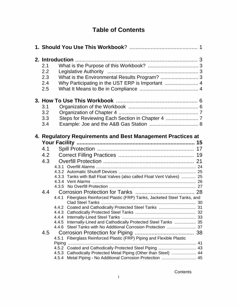
Table of Contents
1. Should You Use This Workbook? ............................................. 1
2. Introduction ................................................................................. 32.1 What is the Purpose of this Workbook? .................................... 32.2 Legislative Authority ................................................................. 32.3 What is the Environmental Results Program? ........................... 32.4 Why Participating in the UST ERP is Important ........................ 42.5 What It Means to Be in Compliance .......................................... 4
3. How To Use This Workbook ...................................................... 63.1 Organization of the Workbook .................................................. 63.2 Organization of Chapter 4 ......................................................... 73.3 Steps for Reviewing Each Section in Chapter 4 ....................... 73.4 Example: Joe and the A&B Gas Station ................................... 8
4. Regulatory Requirements and Best Management Practices atYour Facility .............................................................................. 154.1 Spill Protection ................................................................ 174.2 Correct Filling Practices .................................................. 194.3 Overfill Protection ............................................................ 21
4.3.1 Overfill Alarms .................................................................................... 244.3.2 Automatic Shutoff Devices ................................................................. 254.3.3 Tanks with Ball Float Valves (also called Float Vent Valves) ............ 254.3.4 Vent Alarms ....................................................................................... 264.3.5 No Overfill Protection ......................................................................... 27
4.4 Corrosion Protection for Tanks ....................................... 284.4.1 Fiberglass Reinforced Plastic (FRP) Tanks, Jacketed Steel Tanks, and
Clad Steel Tanks ................................................................................ 304.4.2 Coated and Cathodically Protected Steel Tanks ............................... 314.4.3 Cathodically Protected Steel Tanks ................................................... 324.4.4 Internally-Lined Steel Tanks .............................................................. 334.4.5 Internally-Lined and Cathodically Protected Steel Tanks .................. 354.4.6 Steel Tanks with No Additional Corrosion Protection ........................ 37
4.5 Corrosion Protection for Piping ....................................... 384.5.1 Fiberglass Reinforced Plastic (FRP) Piping and Flexible Plastic Piping ............................................................................................................ 414.5.2 Coated and Cathodically Protected Steel Piping ................................ 434.5.3 Cathodically Protected Metal Piping (Other than Steel) ..................... 444.5.4 Metal Piping - No Additional Corrosion Protection ............................. 45

Contents ii
4.6 Cathodic Protection ......................................................... 474.7 Leak Detection For Tanks ............................................... 52
4.7.1 Automatic Tank Gauging (ATG) ............................................................. 564.7.2 Interstitial Monitoring for Double-Walled Tanks ..................................... 574.7.3 Tank Tightness Testing .......................................................................... 594.7.4 Inventory Control .................................................................................... 614.7.5 Inventory Control for Single-Walled Waste Oil Tanks Less Than 2,000
Gallons ................................................................................................... 634.8 Leak Detection for Piping ................................................ 66
4.8.1 Leak Detection: Pressurized Piping ....................................................... 68 4.8.1.1 Leak Detection: Automatic Line Leak Detectors (LLDs) ................ 70
4.8.2 Leak Detection: Suction Piping .............................................................. 714.8.3 Leak Detection: Line Tightness Testing ................................................. 73
4.9 What To Do For Suspected And Confirmed Releases .... 754.10 Financial Responsibility .................................................. 774.11 Temporarily Closed UST Systems .................................. 83
5. Stage I and Stage II Vapor Recovery Systems5.1 Stage I Vapor Recovery .................................................. 85
5.1.1 Overview - Stage1 ................................................................................. 855.1.2 Rhode Island Regulations ...................................................................... 895.1.3 Requirements ......................................................................................... 89 5.1.3.1 Control Systems ............................................................................ 89
5.1.3.2 Gasoline Storage Vessel (Tank) Requirements, Gasoline DeliveryVessel (Cargo Tank) Requirements .......................................................... 905.1.3.3 Operators of Gasoline Dispensing Facilities .................................. 915.1.3.4 Records ......................................................................................... 915.1.3.5 Compliance & Compliance Test Methods ..................................... 91
5.1.4 Stage I Weekly Inspection Information .................................................. 925.1.5 Stage I Vapor Recovery Components ................................................... 92
5.2 Stage II Vapor Recovery ................................................. 965.2.1 Overview - Stage II ................................................................................ 965.2.2 Federal Regulations ............................................................................... 975.2.3 Rhode Island Regulations ...................................................................... 985.2.4 Requirements ......................................................................................... 98
5.2.4.1 Exemptions .................................................................................... 995.2.4.2 Installation of Stage II Vapor Recovery Systems .......................... 995.2.4.3 General Maintenance and Inspection Requirements .................... 99
5.2.5 Testing, Record Keeping & Reporting Requirements .......................... 1005.2.5.1 Facility Information ...................................................................... 1005.2.5.2 Testing Requirements ................................................................. 1015.2.5.3 Record Keeping ........................................................................... 1015.2.5.4 Weekly Visual Inspection Information .......................................... 102

Contents iii
Appendices
A. For More InformationB. Sample Placards for Overfill DevicesC. Sample Emergency Numbers ListD. Cathodic Protection Testing FormE. Impressed Current 60 Day Inspection FormF. Sample 30-Day Release Detection Monitoring RecordG. Sample Daily Inventory Worksheets H. Manual Tank Gauging Record for Waste Oil Tanks Less than 2,000
GallonsI. Registration Form J. Transfer of Certification of Registration
Inside Front CoverGuide For Periodic Walk-Through Inspections
Inside Back CoverReminder of Typical Ongoing Testing Requirements for UST Systems

This Page Intentionally Left Blank

Chapter 1 1
Chapter 1: Should You Use This Workbook?
This Workbook is designed to help owners and operators of underground storage tanks(commonly referred to as USTs) with the Rules and Regulations For Underground StorageFacilities Used For Petroleum Products and Hazardous Materials, effective October 22, 2002. The Workbook describes requirements and best management practices (BMPs) for your USTsystems and helps you to determine whether your underground storage tanks are incompliance with the regulations.
The DEM has developed and implemented an Environmental Results Program (ERP). Ifyou have underground storage tanks at your facility that meet the criteria described onthe following page, you must read and fill out the checklist questions that accompanythis Workbook. If, after reading this section, you determine that the Workbook does notapply to you, fill out the Non-Applicability Statement included in the accompanyingforms booklet and send it to the DEM. This will inform the DEM that you do not have any USTsystems that fall under this program. If you complete a Non-Applicability Statement, the DEMshould not send you a workbook next year.
For each UST system that you operate, you are required to complete and submit the Compliance Certification Checklist and Certification Statement (and, if required, a Return to Compliance Plan form) and return these forms to the DEM. The Compliance CertificationChecklist, Statement, and Return to Compliance Plan forms are included in the accompanying Forms Booklet. As part of the UST ERP program, the DEM will conduct random and targetedinspections. If you do not meet the above requirements, you will be targeted. Carefullyreview this Workbook to make sure that you understand the requirements you must meet andthat you are able to accurately fill out the Compliance Certification Checklist, Certification Statement, and the Return to Compliance Plan forms.
To determine whether you must complete the required UST ERP Certification forms:• Read and answer the question in this chapter. • Use the information below the question to help you answer the question.• Follow the directions in the grey box below the question.

2
How many UST systems at your facility meet at least one of thefollowing criteria? These are types of UST systems covered by this Workbook.
Numberof USTs
• contain hazardous materialsExamples:a) contain petroleum or used oil (destined for recycling) at public gasoline stations or
repair shops b) private petroleum tanks used for fueling of business vehicles (for example: bus
terminals)c) store fuel for use by emergency power generatorsd) contain heating oils (fuel oils used for the purpose of producing heat)
• holding tanks that serve floor drains or other piping outlets
• If you have at least one UST system that meets the criteria above, complete the applicableportions of the Compliance Certification Checklist and Forms Booklet. Please note the list ofexemptions below.
• If you have no UST systems that meet the criteria above, you do not have any UST systemscovered by the Environmental Results Program. This workbook does not apply to you. Fill out theNon-Applicability Statement included in the accompanying Forms Booklet and send it to the DEM.
Exempt UST Systems: An UST system that meets at least one of the criteria below is anexception to the UST systems you identified above and is not covered by the UST ERP. If youreceived this Workbook, it would be uncommon for all of your tanks to meet at least one of the criteriabelow.
Types and use of tanks• hydraulic lift tanks• storage tanks located entirely within structures, such as a basement or cellar provided that: a) the structure allows for physical access to the storage tank
b) the structure is not part of a secondary enclosure; andc) the tank is situated upon or above the surface of a concrete floor
• septic tanks• pipeline facilities regulated under the Natural Gas Pipeline Safety Act of 1968 or the Hazardous
Liquid Pipeline Safety Act of 1979 • flow through process tanks• USTs storing propane or liquified natural gas• USTs used for the temporary storage of raw materials or products by industry (so called
“Intermittent” or “fill and draw” tanks)• emergency spill protection or overflow tanks• USTs connected to floor drains or other piping outlets which serve residential structures of a 1, 2,
or 3 family dwelling• oil water separators with a planned discharge required to be regulated under the Clean Water Act• residential tanks < or = 1,100 gallons in capacity used for storing #2 heating oil serving a 1, 2, or 3
family dwelling• farm tanks < 1,100 gallons in capacity and storing #2 heating oil for non-commercial purposes
If you are still not sure whether the UST ERP applies to you, call the DEM at(401) 222-2797. You may face substantial penalties if you intentionally falsify yourapplicability. The DEM will be checking your responses for accuracy.

Chapter 2 3
Chapter 2: Introduction2.1 What is the Purpose of this Workbook?
This Workbook is designed to:
• Clearly explain the environmental, record keeping, and compliance requirements and bestmanagement practices that apply to UST systems; and
• Assist owners and operators of regulated UST systems in Rhode Island to participate in theERP.
2.2 Legislative Authority
Rhode Island law requires UST system owner/operators who answered “Yes” to the question inthe previous chapter to comply with the RI DEM UST ERP. These owner/operators are requiredto complete and submit the applicable checklist questions in the accompanying Forms Booklet,complete and submit the Compliance Certification Statement, and, if necessary, complete andsubmit a Return to Compliance Plan(s) for any aspects of their UST system(s) that aredetermined to be out of compliance.
2.3 What is the Environmental Results Program?
The Environmental Results Program (ERP) is a common sense approach to achievingenvironmental protection. It was first developed and used successfully by Massachusetts in1997. The DEM believes that the ERP will assist UST system owners and operators inunderstanding and complying with UST system regulations and lead to exceedingenvironmental standards. The ERP gives you the information to understand the maintenanceand operational requirements that pertain to your UST systems while improving accountability tothe public for environmental performance.
Rhode Island’s Environmental Results Program includes:
• this Workbook which includes best management practices and compliance requirements. The Workbook has a direct relation to the Compliance Certification forms mentioned below;
• a Compliance Certification Checklist of questions that are required to be completed bythe owner/operator. This checklist is included in the accompanying Forms Booklet;
• a Certification Statement form that UST system owners and operators are required tocomplete, sign, and return to the DEM. On the form, the UST system owners and operatorsmust certify the current compliance status of the facility and acknowledge that the facilitymust comply with all applicable environmental laws. This form is included in theaccompanying forms booklet;
• a Return to Compliance Plan form which is used for compliance problems identified in theprocess of filling out the Compliance Certification Checklist and that cannot be correctedprior to submittal of the certification forms. The Return to Compliance Plan describes what
1While this Workbook addresses most RI DEM environmental requirements that apply to UST systems, yourfacility may need to meet additional requirements that are not covered in this Workbook or in the UST ERP. Forexample, requirements related to Class V injection wells (motor vehicle waste disposal wells such as a gas stationwith a service floor drain that leads to a septic system), aboveground storage tanks, hazardous substances, usedtires, and other requirements may apply to your facility as well. Also, this Workbook does not address liability forpollution or spills that may have occurred on your property in the past. If you are unsure whether additionalrequirements apply to your facility, please call RI DEM at (401) 222-2797.
Chapter 2 4
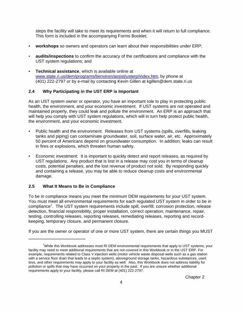
steps the facility will take to meet its requirements and when it will return to full compliance. This form is included in the accompanying Forms Booklet;
• workshops so owners and operators can learn about their responsibilities under ERP;
• audits/inspections to confirm the accuracy of the certifications and compliance with theUST system regulations; and
• Technical assistance, which is available online at www.state.ri.us/dem/programs/benviron/assist/usterp/index.htm, by phone at (401) 222-2797 or by e-mail by contacting Kevin Gillen at [email protected]
2.4 Why Participating in the UST ERP is Important
As an UST system owner or operator, you have an important role to play in protecting publichealth, the environment, and your economic investment. If UST systems are not operated andmaintained properly, they could leak and pollute the environment. An ERP is an approach thatwill help you comply with UST system regulations, which will in turn help protect public health,the environment, and your economic investment.
• Public health and the environment: Releases from UST systems (spills, overfills, leakingtanks and piping) can contaminate groundwater, soil, surface water, air, etc. Approximately50 percent of Americans depend on groundwater consumption. In addition, leaks can resultin fires or explosions, which threaten human safety.
• Economic investment: It is important to quickly detect and report releases, as required byUST regulations. Any product that is lost in a release may cost you in terms of cleanupcosts, potential penalties, and the lost revenue of product not sold. By responding quicklyand containing a release, you may be able to reduce cleanup costs and environmentaldamage.
2.5 What It Means to Be in Compliance
To be in compliance means you meet the minimum DEM requirements for your UST system. You must meet all environmental requirements for each regulated UST system in order to be incompliance1. The UST system requirements include spill, overfill, corrosion protection, releasedetection, financial responsibility, proper installation, correct operation, maintenance, repair,testing, controlling releases, reporting releases, remediating releases, reporting and record-keeping, temporary closure, and permanent closure.
If you are the owner or operator of one or more UST system, there are certain things you MUST

Chapter 2 5
do by law in order to protect human health and the environment. You are responsible forpreventing and quickly detecting releases from your UST systems. You are alsoresponsible for reporting and cleaning up any releases that occur. You will be held accountableif your UST system(s) leak. Therefore, you should do everything in your ability to ensurereleases do not occur.
For further regulatory information, see either of the following:
The Federal UST regulations, 40 Code of Federal Regulations Part 280, are located at:
http://www.epa.gov/oust/fedlaws/cfr.htm#40cfr280
The DEM UST regulations are located at:
http://www.state.ri.us/dem/pubs/regs/regs/waste/ust1002.pdf

This Page Intentionally Left Blank

Chapter 3 6
Chapter 3: How To Use This WorkbookRead this chapter to learn how to use this Workbook. This chapter will tell you:
• what kind of information is contained in the rest of the Workbook,• how that information is organized,• how to work through Chapters 4 and 5,• how a facility would fill out a section of Chapter 4 or 5, and• what the symbols mean in Chapters 4 and 5.
3.1 Organization of the Workbook
You have already read Chapter 1 and Chapter 2. Chapter 1 showed you that you have at leastone regulated UST system, and that you need to complete and submit the questions thataccompany this Workbook and complete and submit Compliance Certification forms to theDEM (and, if required, a Return to Compliance Plan form). Chapter 2 explained what the ERPis and why it is important to comply with regulations. This chapter will help you understand therest of the Workbook. After Chapter 3, there are three major parts of the Workbook: Chapter 4: Regulatory Requirements and Best Management Practices at Your FacilityChapter 4 will help you understand what you have to do to comply with UST regulations and toimprove the environmental performance of your facility. You should review the material inChapter 4 so that you will know how to complete the Compliance Certification Checklist andCertification Statement that you will need to send to the DEM.
Do not be worried by the size of Chapter 4. Most likely, only some parts of the sectionsin Chapter 4 will apply to your facility. You should review all sections that apply to yourUST system(s) but you do not need to review the work if part of the section does notapply to your UST system(s). Each section in Chapter 4 will help you easily decidewhether you should review the parts of that section.
Chapter 5: Stage I and Stage II Vapor Recovery System RequirementsChapter 5 will help you understand what you have to do to comply with the stage I and stage IIvapor recovery system regulations and to improve the environmental performance of yourfacility.
AppendicesThe appendices contain information to help you understand the Workbook and comply with theregulations. They include forms and checklists that can help you stay in compliance. AppendixA also provides a list of UST program contacts and other resources that can help answer yourquestions.
In addition, the front and back covers of this Workbook contain other important information toreview:• the inside front cover has a guide you can use to do periodic walk-through inspections; and• the inside back cover lists activities you need to do, even after finishing the Workbook.

Chapter 3 7
3.2 Organization of Chapter 4
Chapter 4 will help you understand environmental requirements that apply to your facility. Thebeginning of Chapter 4 has a table for you to identify UST systems at your facility. You will usethis information when reviewing the checklists and tables in Sections 4.1 through 4.11. Each ofthose sections covers a different part of the UST system requirements. You must review each ofthe 11 sections in Chapter 4 to see if they apply to your facility. Following your review of thesections, complete the Compliance Certification Checklist, Certification Statement, and anynecessary Return to Compliance Plan forms found in the Forms Booklet that accompanies thisWorkbook.
Sections 4.1 through 4.11 contain: • information on determining which compliance option your UST system uses to meet the
requirements in that section, • a table for you to identify the compliance options each UST system uses, • lists of requirements and best management practices for each option,• compliance checklist questions similar to those you must fill out in the accompanying Forms
Booklet for each compliance option that your UST system(s) use, and• summary of compliance questions for all UST systems at your facility.
3.3 Steps for Reviewing Each Section in Chapter 4 DIRECTIONS: Important directions are provided in gray boxes like this one. Read alldirections! There will be specific directions to follow in each section of Chapter 4 that tellyou how to proceed through that section. Below are the steps for completing a thoroughreview of Chapter 4. The example in the next section shows how one facility followed thesedirections to complete the section on overfill protection.
The steps for completing each section in Chapter 4 are as follows:
1. Read the beginning of each section to understand if it applies to your facility. If you aresure it does not apply, you can skip the section. If it does apply, you should review thequestions associated with the section. The section may ask you to fill out a table to identifywhich compliance options are used by each of your UST systems. This table will help youunderstand how to complete the Compliance Certification Checklist questions associatedwith each section. Use the UST identification table at the beginning of Chapter 4 to keeptrack of the UST systems at your facility.
2. Read the information on requirements and best management practices (BMP) contained ineach section. Then work on the checklists in each section as follows:
• Circle the “UST #” at the top of the checklist for each UST system that uses the option ormeets the characteristics of this checklist.
• Answer the questions in the checklist for UST systems that you circled at the top. Circle“Y” for yes or “N” for no in the column below each UST that you circled. Leave allquestions blank for USTs that you did not circle. Skip a question only if you are told to doso.
• Notice that sometimes a question will tell you to complete a different section first to getthe answer for the question. When you do the other section, be sure to come back!
• Transfer your answers for the Workbook questions to the applicable portion of theCompliance Certification Checklist provided in the accompanying Forms Booklet. Thequestions in the Forms Booklet are similar to the questions provided throughout Chapter4 of this ERP Workbook.

Chapter 3 8
Note: If you prefer to answer the Compliance Certification Checklist questions in theForms Booklet directly, without first reviewing and completing the information in thisWorkbook, you may do so. The Workbook and the accompanying checklist questions areorganized to allow you to use this Workbook as a reference when completing theCompliance Certification Checklist questions.
3. Answer the final summary of compliance question for your facility on the last page of manylonger sections (like Section 4.3). The final summary of compliance question asks whetherall of your UST systems are in compliance with the major set of requirements discussed inthat section. If you answered no to any compliance questions in a section, you mustanswer no to this summary of compliance question and complete a Return to CompliancePlan form provided in the Forms Booklet.
You will use the answers to the questions in Chapter 4 to complete your ComplianceCertification Checklist, Certification Statement and, if necessary, Return to Compliance Planform(s). Follow the instructions provided in the Forms Booklet to fill those forms out.
3.4 Example: Joe and the A&B Gas Station
The next few pages tell the story of Joe, the owner of a gas station, and how he filled out a fewparts of Chapter 4 in this Workbook. Joe is not a real person, but we made up his story to helpyou understand how to begin to fill out the information in Chapter 4. Joe's story does not tellyou everything he did to fill out Chapter 4, but his story will help you get started on the right foot.
Joe's example is explained in dark, bold letters over the next few pages. Try to read the wholestory, because it will help you understand how to:
(1) fill out the tables in Chapter 4, (2) complete the compliance checklists in Chapter 4,(3) answer the summary of compliance question in Chapter 4, and(4) fill out the Compliance Certification Checklist, Certification Statement and, ifnecessary, Return to Compliance Plan form(s) provided in the Forms Booklet.
Joe's story begins here...
Joe is the owner of A&B Gas Station on the corner of Elm and Main Streets. He alsoowns Y&Z Gas on the corner of Maple and State Streets. Joe is filling out this Workbookonly for A&B Gas. He will use the information he writes in the Workbook to correctly fillout his checklist questions and his ERP Certification of Compliance form for A&B Gas. He will fill out a separate checklist and a Certification of Compliance form for Y&Z Gas.
Joe received the Workbook in the mail and starts working on the Workbook a little bit at atime. He knows that starting early will help make sure he has time to collect the rightinformation and do everything the right way before the deadline.
Joe has three underground storage tank (UST) systems at A&B Gas. One UST holdsgasoline, one holds kerosene, and one holds used oil. The gasoline UST is"compartmentalized." This means the tank is divided into different sections orcompartments. (Usually, each compartment will have a different product in it.) This tankhas a compartment for regular gasoline and a compartment for premium gasoline.
The three tanks are lined up in a row from east to west. Joe usually calls the gasolinetank the "east tank." He calls the kerosene tank the "middle tank" and the used oil tank

Chapter 3 9
the "west tank." Joe’s kerosene tank is a lot older than his other two tanks, so he doesnot know as much about that tank as he does about the gasoline tank and the used oiltank.
To start, Joe reads Chapters 1, 2, and 3. When he is done, he feels he has a pretty goodidea of how to fill out the Workbook, so he turns to Chapter 4. Joe Identifies the USTs at His Facility
Before Joe can begin filling out any of the questions in Chapter 4, he has to fill out thetable at the beginning of Chapter 4 that helps him keep track of the tanks he has. He willuse the numbers that he gives to each tank in this table (1-5) to identify them in the restof Chapter 4. He follows the directions in the Workbook to put descriptive information for each tank into the table. You can see a copy of Joe's completed table at the bottom of thispage.
Even though the premium and regular gas are stored in the same tank, the directions tellhim to enter each compartment as a separate UST. So Joe calls the premium section ofhis gasoline tank “UST 1”. Joe knows the registration number of this tank, so he putsthat in the “Identification Number” column. Joe fills in the type of product contained inthis compartment and the size of the compartment. In the column called “Other USTIdentification Information” Joe writes that this tank is the east tank, since that is how hethinks of it.
Joe calls the regular compartment of the gasoline tank “UST 2” and fills in theregistration number and location. These are the same as for the premium compartment. He also fills in the size of this compartment and the type of product it holds.
Joe calls his kerosene tank “UST 3”. He does not know this tank’s registration number,so he leaves that blank. He writes in the type of product and size, and that this is themiddle tank.
Joe calls the used oil tank “UST 4” and fills in the information for this tank. He calls thistank the west tank.
Joe has a total of four USTs (since the premium and regular gasoline compartmentscount separately). So he does not put anything in the fifth row of the table.
UST Identification TableUST
NumberIdentification
NumberType of Product Tank Info.
(Single-wall,Double-wall,Lining, etc.)
Piping Info.(Single-wall,Double-wall,Lining, etc.)
TankMaterial
Size(Gallons)
OtherIdentifyingInformation
1 00123 Premium Double Single Steel 4,000 East2 00123 Regular Double Single Steel 6,000 East3 Kerosene Single Double Steel 2,000 Middle4 00012 Used Oil 1,000 West5
Now that Joe has identified all of his USTs, he is ready to look at the other sections inChapter 4. Joe reads the directions and fills out Sections 4.1 and 4.2. He did not have

Chapter 3 10
much trouble with these sections since he read the directions. We join Joe again whenhe starts Section 4.3. This section is a lot like the other sections in the workbook, soseeing how Joe fills it out will help you.
Joe Identifies the Types of Overfill Protection He Has
Joe is not exactly sure what to do when he starts Section 4.3, so he first reads thebeginning of 4.3. He learns that overfill protection is equipment on USTs to preventtanks from overflowing when they are being filled. He also learns that most USTs have tohave at least one type of overfill protection to be in compliance.
Joe sees that there are three kinds of overfill protection that the regulations allow:overfill alarms, ball float valves, and automatic shutoff devices. An overfill alarm goesoff when a tank is close to being full, and can be seen and/or heard. An automaticshutoff device is located at the fill pipe of a tank, and it stops product from flowing into atank that is close to being full. A ball float valve is located inside a tank, and also slowsdown any product flowing into a tank that is almost full.
Joe already knows that he has an alarm for his gasoline tank. The information at thebeginning of 4.3 helps him figure out that he has an automatic shutoff device on hiskerosene tank and no overfill protection for his used oil tank.
At the beginning of Section 4.3, Joe fills out a table that asks about the kind of overfillprotection that each of his USTs has. This table tells him which checklists in 4.3 heneeds to fill out. A copy of Joe's table is at the bottom of this page.
Using the UST numbers from the table he filled out at the beginning of Chapter 4 (shownon the previous page of this story), Joe marks that USTs 1 and 2 have overfill alarms.(Remember that Joe has to think of each section of his gasoline tank as a separate UST.) He also marks that UST 3 (his kerosene tank) has an automatic shutoff device, and UST 4(his used oil tank) has no overfill protection. From this table, he sees that he has to fillout checklists in Sections 4.3.1, 4.3.2, and 4.3.4. He will fill these checklists out next. None of Joe’s USTs have ball float valves or vent alarms, so he can skip Section 4.3.3and 4.3.4.
Choose the types of overfill protection used for each tank bychecking the appropriate boxes
Go to these sectionsfor information and
compliance checklistsUST Number: 1 2 3 4 5
Overfill Alarm X X Section 4.3.1
Automatic Shutoff Device X Section 4.3.2
Ball Float Valve Section 4.3.3Vent Alarm Section 4.3.4No Overfill Protection X Section 4.3.5

Chapter 3 11
Joe Completes the Overfill Alarm Section for His Gasoline Tank
Joe knows he needs to fill out Section 4.3.1 because Joe’s USTs 1 and 2 have overfillalarms and the table at the beginning of 4.3 directed him to Section 4.3.1. Joe turns toSection 4.3.1 and reads about the requirements and best management practices forUSTs with overfill alarms. Using that information, he answers the questions in thischecklist.
A copy of Joe's answers to the questions in Section 4.3.1 is provided here so that youcan follow along. The next few paragraphs will tell you why he answered thequestions the way he did.
At the top of the checklist, he circles the numbers 1 and 2 to show that these two tankshave overfill alarms. He will not answer any questions on this checklist for USTs 3 and4, since they do not have overfill alarms.
Joe recently had a technician check his overfill alarms, so he knows that they are working according to the requirements he sees in the workbook. He answers yes forboth tanks to Questions 1 and 2.
Joe’s Overfill Protection Checklist For USTs With Overfill AlarmsCircle the UST number for each USTthat has an overfill alarm. Fill out the
questions below for each UST youcircled.
UST # = 1 2 3 4 5
Questions Yes (Y) or No (N)
1. Does your overfill alarm activate at 90% oftank capacity or at least one minute before beingoverfilled?
1Y
1N
2Y
2N
3Y
3N
4Y
4N
5Y
5N
If no, have a qualified person adjust your overfill device to the right height. Also,submit a Return to Compliance plan and submit it with your Certificate ofCompliance.
2. Can your overfill alarm be seen and/or heardfrom the delivery location so that it will alert thedelivery person that the tank is almost full?
1Y
1N
2Y
2N
3Y
3N
4Y
4N
5Y
5N
If no, have a qualified person fix your overfill alarm so that it can be heard and/orseen from the delivery location. Also, submit a Return to Compliance plan andsubmit it with your Certificate of Compliance.

Chapter 3 12
Joe Completes the Automatic Shutoff Device Section for His KeroseneTank
Joe knows that he needs to fill out Section 4.3.2 since the table at the beginning of 4.3told him to fill out this section for his kerosene tank, which has an automatic shutoffdevice. He reads the information about automatic shutoff devices before he answersthe questions. The questions about automatic shutoff devices are like the questionsJoe answered about overfill alarms.
A copy of Joe's answer to the question in Section 4.3.2 is provided here so that youcan follow along. The next few paragraphs will tell you why he answered the questionthe way he did.
Joe starts by circling UST 3 at the top of the checklist, since that is the only tank he haswith an automatic shutoff device. He does not circle the other tanks, and will notanswer any questions for them.
Joe’s kerosene tank overflowed when it was being filled last month. So Joe does notthink his automatic shutoff device is working, and circles “no” for the applicablequestion. He sees that he will have to have a qualified person fix his automatic shutoffdevice so that he can be in compliance with the requirements for automatic shutoffdevices.
In addition to having a qualified person fix his automatic shutoff device, Joe reads thedirections that tell him he must submit a Return to Compliance Plan and submit thiswith his Certification of Compliance. Since Joe answered “no” to this question, he mustanswer “no” to the summary of compliance question at the end of Section 4.3. He fillsout a Return to Compliance Plan form included in his forms booklet. The Return toCompliance Plan tells the DEM how and when Joe will fix the problem. Joe will submitthe Return to Compliance Plan with his ERP Certification of Compliance form.
Since Joe does not have any tanks with a ball float valve, the table at the beginning ofSection 4.3 tells him he can skip Section 4.3.3. So he turns to Section 4.3.4 next toanswer questions for his tank with no overfill protection.
Joe’s Overfill Protection Checklist For USTs With Automatic ShutoffDevices
Circle the UST number for each UST that has anautomatic shutoff device. Fill out the questions
below for each UST you circled.
UST # = 1 2 3 4 5
Questions Circle Yes (Y) or No (N)
Does your automatic shutoff device properly activate at 95%of tank capacity or before the fittings at the top of the tankare exposed to fuel?
1Y
1N
2Y
2N
3Y
3N
4Y
4N
5Y
5N
If no, then have a qualified person adjust your automatic shutoff device to properly activate at 95% ofthe tank capacity or before the fittings at the top of the tank are exposed to fuel. In addition, fill out aReturn to Compliance plan and submit it with your Certification of Compliance.
Chapter 3 13
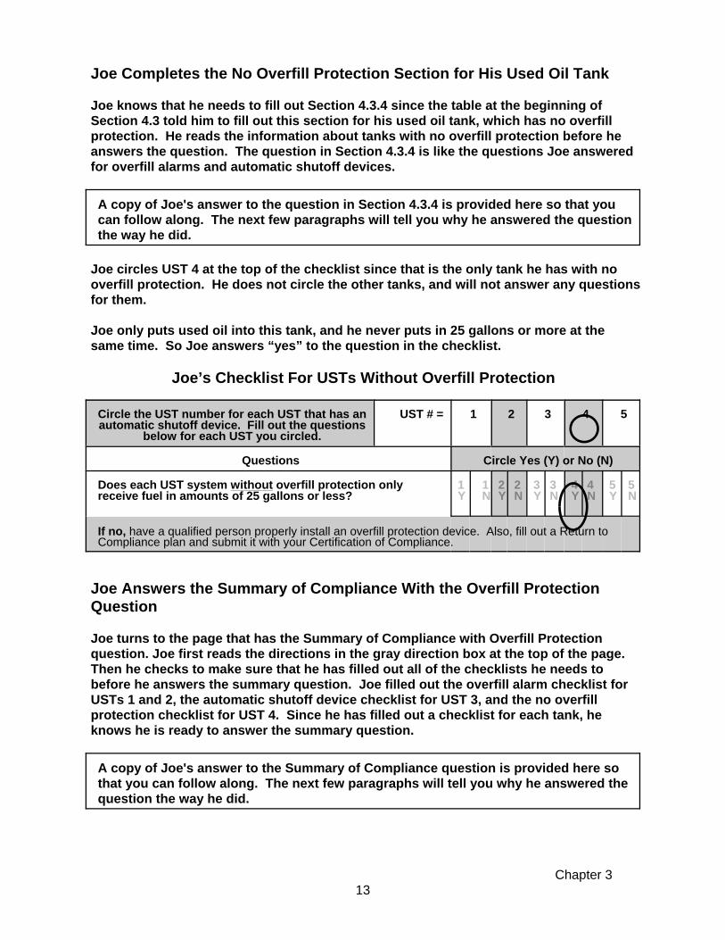
Joe Completes the No Overfill Protection Section for His Used Oil Tank
Joe knows that he needs to fill out Section 4.3.4 since the table at the beginning ofSection 4.3 told him to fill out this section for his used oil tank, which has no overfillprotection. He reads the information about tanks with no overfill protection before heanswers the question. The question in Section 4.3.4 is like the questions Joe answeredfor overfill alarms and automatic shutoff devices.
A copy of Joe's answer to the question in Section 4.3.4 is provided here so that youcan follow along. The next few paragraphs will tell you why he answered the questionthe way he did.
Joe circles UST 4 at the top of the checklist since that is the only tank he has with nooverfill protection. He does not circle the other tanks, and will not answer any questionsfor them.
Joe only puts used oil into this tank, and he never puts in 25 gallons or more at thesame time. So Joe answers “yes” to the question in the checklist.
Joe’s Checklist For USTs Without Overfill Protection
Circle the UST number for each UST that has anautomatic shutoff device. Fill out the questions
below for each UST you circled.
UST # = 1 2 3 4 5
Questions Circle Yes (Y) or No (N)
Does each UST system without overfill protection onlyreceive fuel in amounts of 25 gallons or less?
1Y
1N
2Y
2N
3Y
3N
4Y
4N
5Y
5N
If no, have a qualified person properly install an overfill protection device. Also, fill out a Return toCompliance plan and submit it with your Certification of Compliance.
Joe Answers the Summary of Compliance With the Overfill ProtectionQuestion
Joe turns to the page that has the Summary of Compliance with Overfill Protectionquestion. Joe first reads the directions in the gray direction box at the top of the page. Then he checks to make sure that he has filled out all of the checklists he needs tobefore he answers the summary question. Joe filled out the overfill alarm checklist forUSTs 1 and 2, the automatic shutoff device checklist for UST 3, and the no overfillprotection checklist for UST 4. Since he has filled out a checklist for each tank, heknows he is ready to answer the summary question.
A copy of Joe's answer to the Summary of Compliance question is provided here sothat you can follow along. The next few paragraphs will tell you why he answered thequestion the way he did.

Chapter 3 14
Make sure you have read and completed the checklists in the appropriate overfill protectionsections for all of your USTs before answering the question below.
Joe reads the Summary of Compliance with Overfill Protection question. He knows thathe answered “yes” to the questions for the overfill alarms on USTs 1 and 2 and for nooverfill protection for UST 4. But he answered “No” to the question for the automaticshutoff device for UST 3. So he answers “No” to the Summary of Compliance withOverfill Protection, because he is not in compliance with all overfill protectionrequirements for his tanks. He knows that he has to fill out a Return to Compliance Planform for the automatic shutoff device on UST 3, but that his other tanks are currently incompliance with overfill protection requirements.
Joe will copy his answer to this Summary of Compliance with Overfill Protectionquestion to his Compliance Certification Checklist. So, he will answer "No" to this question on the checklist in the Forms Booklet.
Joe is now ready to move on to Section 4.4 and the other sections of Chapter 4, whichhe will fill out the same way he did Section 4.3.
Joe’s Summary of Compliance With Overfill Protection
Summary Of Compliance With Overfill Protection
Answer the following question: Yes No
Are all of your UST systems in compliance with overfill protection?
To answer YES here, you must be able to answer yes to all applicable questions foreach overfill protection device you have.
X
If you answered NO, fill out a Return to Compliance Plan and submit it with your Certification ofCompliance. A Return to Compliance plan can be found in the accompanying Forms Booklet.
You are now ready to review Chapters 4 and 5 in this workbook! Chapters 4 and5 will help you complete the required Compliance Certification Checklist, CertificationStatement and, if necessary, Return to Compliance Plan form(s) too. Do not forget thatif you need help with this workbook, you can call the DEM. The phone number for helpis on the front cover of this workbook and in the Forms Booklet.

This Page Intentionally Left Blank
Chapter 415
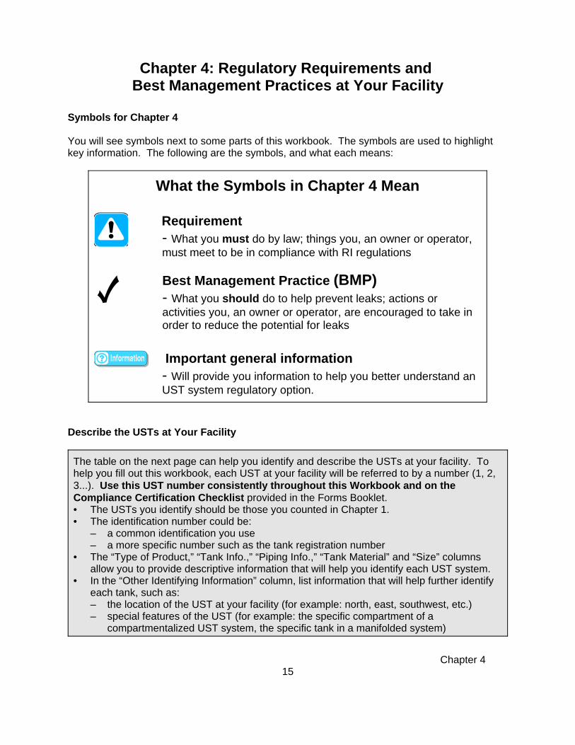
What the Symbols in Chapter 4 Mean
Requirement - What you must do by law; things you, an owner or operator,must meet to be in compliance with RI regulations
Best Management Practice (BMP)- What you should do to help prevent leaks; actions oractivities you, an owner or operator, are encouraged to take inorder to reduce the potential for leaks
Important general information- Will provide you information to help you better understand anUST system regulatory option.
Chapter 4: Regulatory Requirements and Best Management Practices at Your Facility
Symbols for Chapter 4
You will see symbols next to some parts of this workbook. The symbols are used to highlightkey information. The following are the symbols, and what each means:
Describe the USTs at Your Facility
The table on the next page can help you identify and describe the USTs at your facility. Tohelp you fill out this workbook, each UST at your facility will be referred to by a number (1, 2,3...). Use this UST number consistently throughout this Workbook and on theCompliance Certification Checklist provided in the Forms Booklet.• The USTs you identify should be those you counted in Chapter 1.• The identification number could be:
– a common identification you use– a more specific number such as the tank registration number
• The “Type of Product,” “Tank Info.,” “Piping Info.,” “Tank Material” and “Size” columnsallow you to provide descriptive information that will help you identify each UST system.
• In the “Other Identifying Information” column, list information that will help further identifyeach tank, such as:– the location of the UST at your facility (for example: north, east, southwest, etc.)– special features of the UST (for example: the specific compartment of a
compartmentalized UST system, the specific tank in a manifolded system)

Chapter 416
Unique Circumstances - If you have any of the following characteristics at your facility, readthe instructions below. If not, begin to fill out the UST identification table below.
• More than five USTs at your facility covered by this workbook - Make copies of thetable below. Change the UST numbers on each copy to show your additional tanks (6, 7, 8,etc). Also, copy the appropriate checklist questions in Chapter 4 and in the ComplianceCertification Checklist for these USTs.
• Compartmentalized tanks - A compartmentalized tank is one tank that has multiplesections and can contain different products. Each section is called a compartment. If youhave a compartmentalized tank, treat each compartment as a separate UST as youcomplete this workbook and the Compliance Certification Checklist.
• Manifolded tanks - Manifolded tanks are two or more tanks connected by piping whichshare the same type of product or fuel. If you have manifolded tanks, treat each manifoldedtank as a separate UST when completing this workbook and the Compliance CertificationChecklist.
• Temporarily Closed USTs - Temporarily closed USTs only have to meet certainrequirements. Go to Section 4.11 for information about these USTs.
• Dual-Usage Tanks - A dual-usage tank is a UST in which its contents serve more than oneuse. (For example, the contents of the UST serve both a boiler and a diesel generator.) Such tanks are treated under the usage which is more stringently regulated.
UST Identification TableUST
NumberIdentification
NumberType ofProduct
Tank Info.(Single-wall,Double-wall,Lining, etc.)
Piping Info.(Single-wall,Double-wall,Lining, etc.)
TankMaterial
Size(Gallons)
OtherIdentifyingInformation
Example 00123 Premium Double Double Steel 10,000 Southeast
12345

Chapter 4 Section 4.117
Sample Spill Bucket/Cross-Section
Sample SpillProtection
Sample Fill Area
Sample Spill Protection
Section 4.1: Spill ProtectionSpill protection may be provided by a spill containment basin (a/k/a spillbucket/catchment basin) or similar device that contains drips and spills of fuelthat may occur when the delivery hose is uncoupled from the fill pipe.
• Spill basin must be capable of holding aminimum of 3 gallons.
• Spill protection is not designed to contain fuelfor long periods of time.
• Some spill protection devices have a drainvalve or manual pump that allows you to drainaccumulated fuel into your tank. But, when youpump out or drain your spill protectionequipment into your tank, water and debris mayalso enter the tank. If it does not have a drainvalve or pump, then any accumulated fuel orwater must be removed manually and disposedof properly (i.e., not on the ground).
If you know you have spill protection, turn to the next page.
If you don’t know whether you have spill protection, do the following:- Lift each fill port lid and look to see if you have containment around your fill pipe.- Look through your old papers and files to see if you have you have records of spill
protection being installed.- Contact the contractor who installed your underground storage tank.- Contact your service contractor/environmental consultant for assistance.

Chapter 4 Section 4.118
To determine requirements and BMPs for spill protection of your tank(s), read therequirements and BMPs that follow and fill out the ensuing checklist.
Requirements and Best Management Practices for Spill Protection
All USTs are required to have spill containment basins around all fill pipes. Spill containment basins are required to be properly maintained and kept free of water,product, or debris. (Note: Above-ground fill pipes may have different requirements.)
Periodically check to see if your spill protection will hold liquid.
Periodically inspect your spill protection for signs of wear, cracks, or holes.
Make sure your spill protection is empty of liquid and debris before and after eachdelivery.
Checklist for Spill Protection
UST # = 1 2 3 4 5
QUESTIONS: N/A N/A N/A N/A N/A
Circle the appropriate answer
Yes (Y) or No (N)
1. Does your UST system have spill protection? 1Y
1N
2Y
2N
3Y
3N
4Y
4N
5Y
5N
If you answered YES for an UST, you must answer the remaining questions in this checklist for thatUST. If no, then have spill protection (such as a spill bucket) properly installed as soon as possible. Ifthis can’t be completed prior to submitting your Compliance Certification Checklist, you must alsocomplete a Return to Compliance Plan form.
2. Will your spill protection prevent the release of fuel to theenvironment when the transfer hose is detached from the fillpipe? (spill bucket is free of liquid and debris)
1Y
1N
2Y
2N
3Y
3N
4Y
4N
5Y
5N
If no, have your spill protection emptied, repaired or replaced as soon as possible so that it will preventa release to the environment when the transfer hose is detached from the fill pipe. If this can’t becompleted prior to submitting your Compliance Certification Checklist, you must also complete a Returnto Compliance Plan form.
Chapter 4
Section 4.219
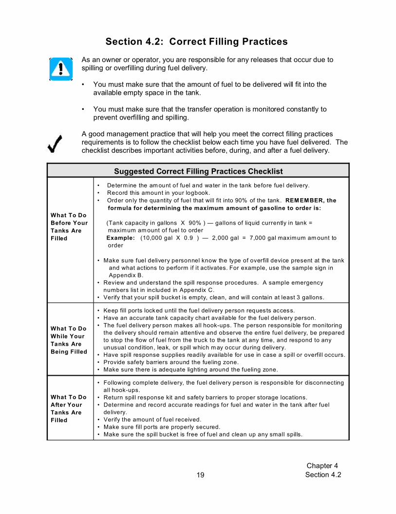
Section 4.2: Correct Filling Practices
As an owner or operator, you are responsible for any releases that occur due tospilling or overfilling during fuel delivery.
• You must make sure that the amount of fuel to be delivered will fit into theavailable empty space in the tank.
• You must make sure that the transfer operation is monitored constantly toprevent overfilling and spilling.
A good management practice that will help you meet the correct filling practicesrequirements is to follow the checklist below each time you have fuel delivered. Thechecklist describes important activities before, during, and after a fuel delivery.
Suggested Correct Filling Practices Checklist
What To Do
Before Your
Tanks Are
Filled
• Determine the am ount of fuel and water in the tank before fue l delivery.
• Record this amount in your logbook.
• Order only the quantity of fuel that will fit into 90% of the tank. REMEMBER, the
formula for determining the maximum amount of gasoline to order is:
(Tank capacity in gallons X 90% ) — gallons of liquid currently in tank =
maximum am ount of fuel to order
Example: (10,000 gal X 0.9 ) — 2,000 gal = 7,000 gal maximum am ount to
order
• Make sure fuel delivery personnel know the type of overfill device present at the tank
and what actions to perform if it activates. For example, use the sample sign in
Appendix B.
• Review and understand the spill response procedures. A sample emergency
numbers list in included in Appendix C.
• Verify that your spill bucket is empty, clean, and will contain at least 3 gallons.
What To Do
While Your
Tanks Are
Being Filled
• Keep fill ports locked until the fue l delivery person requests access.
• Have an accurate tank capacity chart available for the fuel delivery person.
• The fuel delivery person makes all hook-ups. The person responsible for monitoring
the delivery should remain attentive and observe the entire fuel delivery, be prepared
to stop the flow of fuel from the truck to the tank at any time, and respond to any
unusual condition, leak, or spill which m ay occur during delivery.
• Have spill response supplies readily available for use in case a spill or overfill occurs.
• Provide safety barriers around the fueling zone.
• Make sure there is adequate lighting around the fueling zone.
What To Do
After Your
Tanks Are
Filled
• Following complete delivery, the fuel delivery person is responsible for disconnecting
all hook-ups.
• Return spill response kit and safety barriers to proper storage locations.
• Determine and record accurate readings for fuel and water in the tank after fuel
delivery.
• Verify the amount of fuel received.
• Make sure fill ports are properly secured.
• Make sure the spill bucket is free of fuel and clean up any small spills.

Chapter 4
Section 4.220
Checklist for Requirements for Correct Filling Practices
ANSWER THE FOLLOW ING QUESTIONS: YES NO
1. Do you have procedures that ensure the am ount of fuel to be delivered will fit
into the tank for each delivery at your facility?
If no, make sure that the amount of fuel to be delivered will fit into the tank it is being placed into. Make
sure you do this for each delivery.
2. Do you have procedures to ensure that each delivery is monitored constantly
to prevent overfilling and spilling?
If no, put procedures in place to ensure that each delivery is monitored constantly to prevent overfilling
and spilling.
3. Do you have spill response supplies and safety barriers available during filling
operations ?
If no, make such items available to whomever is conducting the filling operation.

Chapter 4 Section 4.321
To determine the various types of overfill protection of your UST system(s), identify thetype(s) of overfill protection you have for each UST. Note: Different tanks at your facility may have different types of overfill protection. Select the appropriate type of overfill protection for each tank at your facility.Note: Some of the tanks at your facility may have two or more types of overfillprotection. Only choose the type of overfill protection you are using to comply withthe overfill protection portion of the UST regulations.
Section 4.3: Overfill ProtectionOverfill protection is equipment installed on the UST to help prevent your tanksfrom being overfilled during fuel delivery. Overfill protection is designed to stopfuel flow, reduce fuel flow, or alert the delivery person during delivery before thetank becomes full and begins releasing petroleum into the environment.
There are four common types of overfill protection: • overfill alarms • ball float valves• automatic shutoff devices• vent alarms
What Type(s) Of Overfill Protection Do You Have for Each Tank at Your Facility?
Go to these sections forinformation and
compliance checklistsUST Number: 1 2 3 4 5
Overfill Alarm Section 4.3.1Automatic Shutoff Device Section 4.3.2Ball Float Valve Section 4.3.3Vent Alarm Section 4.3.4No Overfill Protection Section 4.3.5
If you know the type(s) of overfill protection you have, skip the descriptions below andproceed as instructed in the table above. Otherwise, take the following steps to figureout what is at your facility:• Read the following information to help determine your type(s) of overfill protection. If you still
have problems, then• Look through your old records to see if they help you. • Contact the contractor who installed your underground storage tank.• Contact your service contractor/environmental consultant for assistance.

Chapter 4 Section 4.322
Sample Schematic for anOverfill Alarm
Sample Overfill Alarm
Looking Through the End ofAutomatic Shutoff Device
Looking Down a Fill Pipe atan Automatic Shutoff Device
Diagram of anAutomatic Shutoff
Device
Descriptions of the Different Types of OverfillProtection
Overfill Alarm - This type has a remote indicator locatedon a structure, such as the wall of a building near the tank. It is typically connected to a continuous monitoring devicesuch as an automatic tank gauge, and provides an audibleand/or visual warning to the delivery person when the tankis close to being full.
Automatic Shutoff Device - This type is a mechanicaldevice located at the fill pipe of your tank. Look down yourfill pipe to see part of this device. It will be similar to thepicture below. You will see what appears to be a linecutting through your fill pipe (or a half moon shape in yourfill pipe).

Chapter 4 Section 4.323
SampleBall Float
Valve
Sample Ball FloatValves
Sample Extractor PortCloseup of Extractor
Port
Sample ofVent Alarm
Sample ofVent Alarm
Ball Float Valve - You might find it difficult todetermine whether or not you have this type ofoverfill protection because it is located inside thetank where the vent line exits the tank. You mightbe able to find an extractor port for the ball floatvalve (see picture below). Otherwise, you will needto look through your installation paperwork or callyour contractor to determine whether your tank hasthis type of overfill protection.
Vent Alarm - A vent alarm is a small device, usually a tube, which is typically installed between your tankand the vent pipe. It signals that the tank is full, thereby minimizing the chance of overfilling. When oil ispumped into your tank, air is displaced from inside the tank through the vent pipe. As the air passesthrough the vent pipe, it makes a whistling sound as it passes through the alarm. When the level of thefuel reaches the end of the tube the whistling stops, which indicates that the tank is full.
You must have overfill protection (for example, an overfill alarm) for every UST filled withmore than 25 gallons of fuel at a time.

Chapter 4 Section 4.324
4.3.1 Overfill Alarms
Overfill alarms use an alarm or warning light to warn the delivery person to stopdelivery because the fuel is approaching the tank capacity. After the alarm goesoff, the delivery person must stop the flow of fuel to the tank.
Requirements and Best Management Practices for Overfill Alarms
The overfill alarm must activate when the fuel in the tank reaches 90% of the tankcapacity or is within one minute of being overfilled.
The overfill alarm must be located so it can be seen and/or heard at the UST systemdelivery location. This ensures the delivery person will be alerted when the tank isalmost full.
A qualified UST contractor should check your overfill alarm annually to make sure itis set at the proper height in the tank and that the overfill alarm activates at 90% ofthe tank capacity or at least one minute before being overfilled. The UST contractorshould manually trip the alarm to be assured that it is functioning properly.
You should educate and alert your delivery person that you have an overfill alarm.One way is to place a sign near each fill pipe (in clear view of the delivery person)saying there is an overfill alarm for that tank, what occurs when it activates, and thenecessary actions to take when it activates. Make sure your sign is durable. Seethe sample sign in Appendix B.
Overfill Protection Checklist for USTs with Overfill Alarms
UST # = 1 2 3 4 5
Questions N/A N/A N/A N/A N/A
Circle the appropriate answer
Yes (Y) or No (N)
1. Does your overfill alarm activate at 90% of tank capacityor at least one minute before being overfilled?
1Y
1N
2Y
2N
3Y
3N
4Y
4N
5Y
5N
If no, have a qualified person adjust your overfill device to the right height. Also, submit a Return toCompliance Plan and submit it with your Certification of Compliance forms.
2. Can your overfill alarm be seen and/or heard from thedelivery location so that it will alert the delivery person thatthe tank is almost full?
1Y
1N
2Y
2N
3Y
3N
4Y
4N
5Y
5N
If no, have a qualified person fix your overfill alarm so that it can be heard and/or seen from thedelivery location. Also, submit a Return to Compliance Plan and submit it with your Certification ofCompliance forms.

Chapter 4 Section 4.325
4.3.2 Automatic Shutoff Devices
The automatic shutoff device slows down and then stops the delivery when thefuel has reached a certain level in the tank by shutting off the flow of fuel to theUST system.
Requirements and Best Management Practices for Automatic Shutoff Devices
Automatic shutoff devices must activate when the fuel in the tank reaches 95% of thetank capacity or before the fittings at the top of the tank are exposed to fuel.
• There must not be any object in the fill pipe that would keep the shutoff mechanism fromactivating.
• The automatic shutoff device must be positioned so that the float arm is not blocked and canmove through its full range of motion.
A qualified UST contractor should check your automatic shutoff device to make surethat it is functioning properly and that the automatic shutoff device activates at 95%of the tank capacity or before the fittings at the top of the tank are exposed to fuel.
Automatic shutoff devices should not be used if your tank receives pressurizeddeliveries because it might result in dangerous situations.
Overfill Protection Checklist for USTs with Automatic Shutoff Devices
UST # = 1 2 3 4 5
Questions N/A N/A N/A N/A N/A
Circle the appropriate answer
Yes (Y) or No (N)
Does your automatic shutoff device properly activate at 95%of tank capacity or before the fittings at the top of the tank areexposed to fuel?
1Y
1N
2Y
2N
3Y
3N
4Y
4N
5Y
5N
If no, then have a qualified person adjust your automatic shutoff device to properly activate at 95% ofthe tank capacity or before the fittings at the top of the tank are exposed to fuel. In addition, fill out aReturn to Compliance Plan and submit it with your Certification of Compliance forms.
4.3.3 Tanks with Ball Float Valves (also called Float Vent Valves)
The ball float valve is installed at the vent line in the tank and restricts vapor flowin an UST system as the tank gets close to being full. As the tank fills, the ballin the valve rises, restricting the flow of vapors out of the UST system duringdelivery. The flow rate of the delivery will decrease noticeably and should alertthe delivery person to stop the delivery.

Chapter 4 Section 4.326
Requirements and Best Management Practices for Ball Float Valves
Ball float valves must activate by restricting fuel flowing into the tank when the fuel inthe tank reaches 90% of the tank capacity or at least 30 minutes before the tank willbe overfilled. For ball float valves to work properly:
• the air hole in the ball float valve must not be plugged,• the ball cage must be intact,• the ball must move freely in the cage,• the ball must seal tightly on the pipe, and• the top of the tank must be air tight during delivery so that vapors cannot escape
from the tank. Everything from other tank access ports to fittings to drainmechanisms on spill buckets must be tight and be able to hold the pressure created when the ball float valve engages.
A qualified UST contractor should check your ball float valve to make sure that it is functioning properly and that the ball float valve activates at 90% of the tank capacityor at least 30 minutes before the tank will be overfilled.
You should not use a ball float valve for overfill protection if any of the followingapply: • Your UST system receives pressurized deliveries• Your UST system has suction piping (see section 4.7.2.3 for information on
suction piping)• Your UST system has coaxial stage I vapor recovery (see Chapter 5 for the
definition of stage I vapor recovery)
Overfills or dangerous situations (for example, pressure could build up in the tank and result ingasoline spraying out into the environment or onto the delivery person) may occur under any ofthe above circumstances.
Overfill Protection Checklist for USTs with Ball Float Valves
UST # = 1 2 3 4 5
Questions
Does your ball float valve activate by restricting flow at 90% oftank capacity or at least 30 minutes prior to overfilling?
1Y
1N
2Y
2N
3Y
3N
4Y
4N
5Y
5N
If no, have a qualified person adjust your ball float valve to the right height so that it restricts flow at90% of the tank capacity. Also, fill out a Return to Compliance Plan and submit it with your Certificationof Compliance forms.
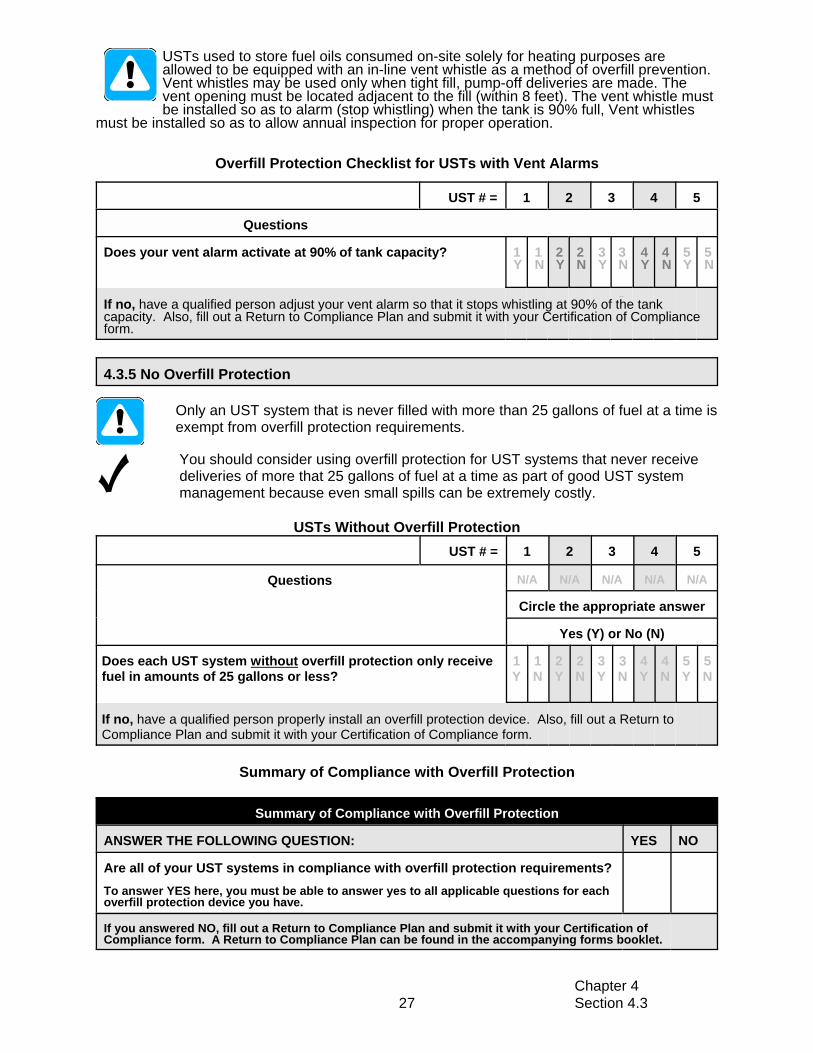
4.3.4 Vent Alarms
Requirements and Best Management Practices for Vent Alarms
The vent alarm is a device that makes a whistling sound as the tank is beingfilled. Once the whistling sound stops, it is an indication that the tank is full.
Chapter 4 Section 4.327
USTs used to store fuel oils consumed on-site solely for heating purposes areallowed to be equipped with an in-line vent whistle as a method of overfill prevention.Vent whistles may be used only when tight fill, pump-off deliveries are made. Thevent opening must be located adjacent to the fill (within 8 feet). The vent whistle mustbe installed so as to alarm (stop whistling) when the tank is 90% full, Vent whistles
must be installed so as to allow annual inspection for proper operation.
Overfill Protection Checklist for USTs with Vent Alarms
UST # = 1 2 3 4 5
Questions
Does your vent alarm activate at 90% of tank capacity? 1Y
1N
2Y
2N
3Y
3N
4Y
4N
5Y
5N
If no, have a qualified person adjust your vent alarm so that it stops whistling at 90% of the tankcapacity. Also, fill out a Return to Compliance Plan and submit it with your Certification of Complianceform.
4.3.5 No Overfill Protection
Only an UST system that is never filled with more than 25 gallons of fuel at a time isexempt from overfill protection requirements.
You should consider using overfill protection for UST systems that never receivedeliveries of more that 25 gallons of fuel at a time as part of good UST systemmanagement because even small spills can be extremely costly.
USTs Without Overfill ProtectionUST # = 1 2 3 4 5
Questions N/A N/A N/A N/A N/A
Circle the appropriate answer
Yes (Y) or No (N)
Does each UST system without overfill protection only receivefuel in amounts of 25 gallons or less?
1Y
1N
2Y
2N
3Y
3N
4Y
4N
5Y
5N
If no, have a qualified person properly install an overfill protection device. Also, fill out a Return toCompliance Plan and submit it with your Certification of Compliance form.
Summary of Compliance with Overfill Protection
Summary of Compliance with Overfill Protection
ANSWER THE FOLLOWING QUESTION: YES NO
Are all of your UST systems in compliance with overfill protection requirements?To answer YES here, you must be able to answer yes to all applicable questions for eachoverfill protection device you have.
If you answered NO, fill out a Return to Compliance Plan and submit it with your Certification ofCompliance form. A Return to Compliance Plan can be found in the accompanying forms booklet.

Chapter 4 Section 4.428
To determine requirements and BMPs for corrosion protection of your tank(s), do thefollowing:1. Identify the type(s) of tank(s) at your facility. Check the appropriate boxes in the
table below.Note: If you have compartmentalized tank(s), treat each compartment as aseparate UST. If you have manifolded tanks, treat each as a separate UST.
2. For each type of tank you checked, go to the section of this Workbook listed in theright column of the table. Read the requirements and best management practicesand fill out the appropriate checklist(s) in that section. You may need to go to morethan one checklist – each tank type has a separate checklist.
Section 4.4: Corrosion Protection for Tanks
If your UST system contains fuel oil that is consumed on-site solely for heatingpurposes, you are not required to have corrosion protection for the tanks.
All of your regulated tanks that are underground and routinely contain regulated substances must be protected from corrosion.
You can protect your underground tank from corrosion in several ways. Your tank may be:• a tank made of a non-corrodible material (such as fiberglass),• a steel tank that is coated and cathodically protected,• a steel tank jacketed or clad with a non-corrodible material, or• a steel tank that is cathodically protected and/or internally-lined.
Internal lining and cathodic protection require periodic operation and maintenance.
All of your underground tanks that were installed after May 8, 1985 need to meet allappropriate construction standards and be installed according to a standard code ofpractice and the manufacturer’s instructions. If your tank was installed before May8, 1985, contact the DEM for information on corrosion protection.
Keep all paperwork related to your corrosion protected tanks (examples includepaperwork related to installation, cathodic protection, integrity assessment, repair,and internal lining).
What Type(s) Of Underground Tank(s) Do You Have at Your Facility? Go to these sections forinformation and
compliance checklistsUST Number: 1 2 3 4 5
Fiberglass Reinforced Plastic (FRP) Tank Section 4.4.1
Jacketed Steel Tank Section 4.4.1
Clad Steel Tank Section 4.4.1
Coated and Cathodically Protected Steel Tank Section 4.4.2
Cathodically Protected Steel Tank Section 4.4.3
Internally-Lined Steel Tank Section 4.4.4
Internally-Lined and Cathodically Protected Steel Tank Section 4.4.5
Steel Tank with No Additional Corrosion Protection Section 4.4.6

Chapter 4 Section 4.429
Note: If your tank type is not listed on the table, contact the DEM to determine what you must
do.
If you know the type(s) of tanks you have, skip the description information below and
proceed as instructed in the table above. Otherwise, take the following steps to figure
out what is at your facility:
• Read the descriptions below of the different tank types.
• Look through your old records to see if they match any of the names in the descriptions.
• Contact the contractor who installed your UST.
Tank Type Descriptions
Fiberglass Reinforced Plastic (FRP) Tank - This tank is made of fiberglass reinforced plastic; examples of tank makers include Owens Corning®, Xerxes®, Cardinal®, Fluid Containment®, andContainment Solutions®.
Jacketed Steel Tank - This is a steel tank that is encapsulated (or “jacketed”) in a non-corrodible, nonmetallic material such as fiberglass or polyethylene. There is a space betweenthe steel wall and the jacket material. This space may be monitored for a breach of either theinner or outer wall. Examples of jacketed tank brands include: Permatank®, Glasteel II®, Titan®,Total Containment®, and Elutron®.
Clad Steel Tank - This is a steel tank that has a thick layer of non-corrodible material such asfiberglass or urethane that is mechanically bonded (clad) to the outer wall of the steel tankwhich helps protect the outer part of the steel wall from corroding. Examples include: ACT-100®, ACT-100-U®, Glasteel®, and Plasteel®.
Coated and Cathodically Protected Steel Tank - This is a steel tank that has both an externalcoating and cathodic protection. An example of a coated and cathodically protected tank brandis the sti-P3® tank. This type of tank is usually installed with galvanic (sacrificial) anodes forcathodic protection. However, these tanks may have an impressed current cathodic protectionsystem if the galvanic (sacrificial) anodes no longer protected the tank from corrosion. If youare not sure whether you have a cathodic protection system, see the “Determining If You HaveCathodic Protection” section on the next page.
Cathodically Protected Steel Tank - This is a steel tank without an external coating that has acathodic protection system. Typically, this type of tank was originally installed as a bare steeltank before May 8, 1985 and had cathodic protection installed at some later date. Usually thistype of tank will have an impressed current cathodic protection system. If you are not surewhether you have a cathodic protection system, see the “Determining If You Have CathodicProtection” section on the next page.
Internally-Lined Steel Tank - This is a steel tank with an internal lining installed. Typically,this type of tank was installed as a bare steel tank before May 8, 1985 and had an internal lininginstalled at some later date.
Internally-Lined and Cathodically Protected Steel Tank - This is a steel tank that has both
internal lining and cathodic protection. Typically, this type of tank was installed as a bare steel
tank before May 8, 1985 and had cathodic protection and internal lining installed at some later

30
Sample RectifierSample Rectifier
4.4.1 Fiberglass Reinforced Plastic (FRP) Tanks, Jacketed Steel Tanks, and CladSteel Tanks
Sample FRP Tank
date. Usually this type of tank will have an impressed current cathodic protection system. If youare not sure whether you have a cathodic protection system, see the “Determining If You HaveCathodic Protection” section below.
Steel Tank with NO Additional Corrosion Protection - This is a steel tank that does not havecathodic protection, an internal lining, nor any non-corrodible material that encapsulates or isbonded to the outside of the tank. These tanks do not meet the UST requirements andtherefore should be permanently closed.
Determining If You Have Cathodic Protection - There are two typesof cathodic protection systems commonly used to protect your steeltank from corrosion - impressed current and galvanic (sacrificial)anodes.
Impressed current system - If you have animpressed current system you will have arectifier (a device for converting alternatingcurrent into direct current) locatedsomewhere at your facility.
Galvanic (sacrificial) anode system - It ismore difficult to tell if you have this type ofcathodic protection system because theanodes are buried and attached to the tank. You cannot see them and there is no rectifier.Look at any installation paperwork you have or contact the contractor who installed the tank orcathodic protection system to try to determine if you have a galvanic (sacrificial) anode system. For example, a sti-P3
® tank commonly uses a galvanic (sacrificial) anode system.
Fiberglass Reinforced Plastic (FRP) tanks, jacketed steel tanks, and clad steeltanks meet the corrosion protection requirements without additional equipment or operation and maintenance.
Best Management Practices for Fiberglass Reinforced Plastic (FRP) Tanks Have your tanks periodically checked for deflection(a measure of the roundness of your tank). Sincethese tanks become brittle, deflection may result incracking or catastrophic failure. Contact your tankmaker for information on deflection testing.

Chapter 4 Section 4.431
Sample Piece of a Jacketed Tank
Sample Clad Tank
4.4.2 Coated and Cathodically Protected Steel Tanks
Sample Coated and CathodicallyProtected Tank
Best Management Practices for Jacketed Steel Tanks
Have your jacketed steel tanksperiodically tested by a qualifiedcontractor to make sure the spacebetween the steel tank and non-corrodible material is tight. Thisspace is known as the interstitialspace or secondary containmentarea. If your primary tank wallwere to have a leak and thesecondary containment space was not tight, a release could result in costly and time-consuming cleanup.
Best Management Practices for Clad Steel Tanks
If you have clad steel tanks that have cathodic protectionthen you should have your cathodic protection systemtested periodically to make sure that it is operatingproperly. Section 4.6 describes procedures for operatingand maintaining your cathodic protection.
Requirements for Coated and Cathodically Protected Steel Tanks
The coating is on the outside of the tank and must be made of a suitable dielectricmaterial (a material that isolates the tank from the surrounding soil and does notconduct electricity). A sti-P3® tank is the most common type of coated andcathodically protected steel tank.
You must comply with specific testing andrecord keeping requirements for cathodicprotection. This information can be found inSection 4.6. Before completing the checkliston the next page, read the cathodic protectionsection and fill out the checklists in that section.

Chapter 4 Section 4.432
4.4.3 Cathodically Protected Steel Tanks
Corrosion Protection Checklist for Coated and Cathodically Protected Steel Tanks
Circle the UST numbers for UST systems that
are coated and cathodically protected steel
tanks. Fill out the questions below for these
tanks.
UST # = 1 2 3 4 5
Questions: N/A N/A N/A N/A N/A
Circle the appropriate answer
Yes (Y) or No (N)
1. Is your tank coated with a suitable dielectric material? 1
Y
1
N
2
Y
2
N
3
Y
3
N
4
Y
4
N
5
Y
5
N
If no, contact the DEM to determine how you may return to compliance.
2. Do you meet the requirements for your cathodic protection
system? To answer “Yes” here, you m ust be in compliance with
all cathodic protection requirements in Section 4.6. Complete the
cathodic protection system checklist in Section 4.6.
1
Y
1
N
2
Y
2
N
3
Y
3
N
4
Y
4
N
5
Y
5
N
If no, you must take action to comply with the requirements in Section 4.6, “Cathodic Protection System
Check list.”
Requirements and Best Management Practices for Cathodically Protected SteelTanks
For any steel tank that uses cathodic protection without a dielectric coating for corrosionprotection, installation of that UST system must have begun on or before May 8,1985. If you have a coated and cathodically protected steel tank, see Section 4.4.2.
An integrity assessment of the tank must have been conducted before adding cathodic protection. The DEM requires that the tank be internally inspected by atrained professional who enters the tank to determine if it is structurally sound andfree of corrosion holes.
A code of practice must be followed when adding cathodic protection to your tank,and prior written notification to and approval by the DEM is required.
You must comply with specific testing and record keeping requirements for cathodic protection. This information can be found in Section 4.6. Beforecompleting the checklist on the next page, read the cathodic protection sectionand fill out the checklists in Section 4.6.

Chapter 4 Section 4.433
4.4.4 Internally-Lined Steel Tanks
Keep records of your integrity assessment and cathodic protection installation. These records may be useful in determining whether your tank is in compliance withthe corrosion protection requirements.
Corrosion Protection Checklist for Cathodically Protected Steel Tanks
Circle the UST numbers for UST systems that
are cathodically protected steel tanks. Fill out
the questions below for these tanks.
UST # = 1 2 3 4 5
QUESTIONS: N/A N/A N/A N/A N/A
Circle the appropriate answer
Yes (Y) or No (N)
1. Did the installation for this UST system begin on or before
May 8, 1985?
1
Y
1
N
2
Y
2
N
3
Y
3
N
4
Y
4
N
5
Y
5
N
If no, then return to compliance: Any tank where installation began after May 8, 1985 that is
cathodically protected but not coated does not meet the corrosion protection requirements. Contact theDEM to determine how you may return to compliance.
2. Did this UST system pass an integrity assessment? 1
Y
1
N
2
Y
2
N
3
Y
3
N
4
Y
4
N
5
Y
5
N
If no, contact the DEM to determine how you may return to compliance.
3. Do you meet the requirements for your cathodic protection
system? To answer “Yes” here, you m ust be in compliance with
all cathodic protection requirements in Section 4.6.
1Y
1N
2Y
2N
3Y
3N
4Y
4N
5Y
5N
If no, you must take action to comply with the requirements in Section 4.6, “Cathodic Protection System
Check list.”
Requirements and Best Management Practices for Internally-Lined Steel Tanks
For any steel tank that uses internal lining for corrosion protection, installation of thatUST system must have begun on or before May 8, 1985.
You must keep all records of repairs for the life of the internally-lined tank.
A code of practice must be followed when adding or repairing an interior lining toyour tank and prior written notification to and approval by the DEM is required.

Chapter 4 Section 4.434
Sample of a Tank being Interior Lined
Within 10 years of lining, lined tanks must be internally inspected by a qualifiedcontractor and found to be structurally sound with the lining still performing inaccordance with original design specifications. After the initial 10 year inspection,these inspections must be conducted at least every 5 years.
Keep records of your lining installation and lining inspections. These records may be useful in determining whether your tank is in compliance with the corrosionprotection requirements. Inspection records are required to be kept for three (3)years beyond the life of a facility.
You should consider adding external corrosion protection (such as cathodicprotection) as part of good UST system management.
Corrosion Protection Checklist for Internally-Lined Steel Tanks
Insert the date of your lining installation for each
tank below the appropriate UST # (mm/dd/yy).
Write N/A (not applicable) for any tanks that are
not internally-lined.
UST # = 1 2 3 4 5
1. Did the installation for this UST system begin on or before
May 8, 1985?
1Y
1N
2Y
2N
3Y
3N
4Y
4N
5Y
5N
If no, then return to compliance: Any tank where installation began after May 8, 1985 that is
using internal lining alone does not meet the corrosion protection requirements. These tanks do not
meet the regulatory requirements and must be permanently closed.

Insert the date of your lining installation for eachtank below the appropriate UST # (mm/dd/yy). Write N/A (not applicable) for any tanks that are
not internally-lined.
UST # = 1 2 3 4 5
Chapter 4 Section 4.435
4.4.5 Internally-Lined and Cathodically Protected Steel Tanks
2. Do you have all records of repairs for your lined tank?If your lined tank has never been repaired, then you will not haveany repair records - answer yes to this question.
1Y
1N
2Y
2N
3Y
3N
4Y
4N
5Y
5N
If no, contact the inspector or repair company that worked on your tank lining. Secure a record of anyrepairs you have had completed on your lined tank.
3a. Do you have your lined tank periodically inspected?Inspections are required within 10 years of installation and thenevery 5 years thereafter. If your tank was internally lined less than10 years ago, this question does not yet apply - skip this question.
1Y
1N
2Y
2N
3Y
3N
4Y
4N
5Y
5N
3b. What is the date of your most recent lined tank inspection,if applicable?
If the answer to 3a is no, have a lining inspection conducted on your lined tank.
4. Did your lined tank pass its most recent periodicinspection? If your tank was internally lined less than 10 yearsago, this question does not yet apply - skip this question.
1Y
1N
2Y
2N
3Y
3N
4Y
4N
5Y
5N
If no, contact the DEM to determine how you may return to compliance.
Requirements and Best Management Practices for Internally-Lined andCathodically Protected Steel Tanks
For any steel tank that uses an internal lining and cathodic protection without adielectric coating (see Section 4.4.2) for corrosion protection, installation of the USTsystem must have begun on or before May 8, 1985.
When you combine the use of internal lining and cathodic protection, you must meet specific testing and record keeping requirements for cathodic protection, whichare in Section 4.6. Before completing the checklist on the next page, read thecathodic protection section and fill out the checklists in that section.
You must also meet the lining requirements in Section 4.4.4. Before completing thechecklist on the next page, read the internally-lined steel tank section and fill outthe checklist in that section.
There is one exception which relates to Questions 3 and 4 of the checklist in Section 4.4.4:
• If the integrity of the steel tank was ensured prior to adding cathodic protection, you do nothave to conduct the periodic inspections of the lined tank. The method of integrityassessment is provided in Section 4.4.3 and must determine that the steel tank shell isstructurally sound and free of corrosion holes.

Chapter 4 Section 4.436
Have your internal lining checked periodically even if the inspections are not required.
Keep records of your lining and cathodic protection installations. These records may beuseful in determining whether your tank is in compliance with the corrosion protectionrequirements.
Corrosion Protection Checklist for Internally-Lined and Cathodically Protected Steel Tanks
Circle the UST numbers for USTs that areinternally-lined and cathodically protected. Fill
out the questions below for these tanks.
UST # = 1 2 3 4 5
QUESTIONS: N/A N/A N/A N/A N/A
Circle the appropriate answer
Yes (Y) or No (N)
1. Do you meet the requirements for your cathodic protectionsystem? To answer “Yes” here, you must be in compliance with allcathodic protection requirements in Section 4.6.
1Y
1N
2Y
2N
3Y
3N
4Y
4N
5Y
5N
If no, you must take action to comply with the requirements in Section 4.6, “Cathodic Protection SystemChecklist”
2. Did this UST system pass an integrity assessment at thetime cathodic protection was added? Note: information about the integrity assessment is in Section4.4.3.
1Y
1N
2Y
2N
3Y
3N
4Y
4N
5Y
5N
If no, contact the DEM to determine how you may return to compliance.
3. Do you meet the lining requirements in Section 4.4.4? If you answered yes to all applicable questions in Section 4.4.4 foran UST system, then you meet the lining requirements. You cananswer “Yes” here for that UST system.
1Y
1N
2Y
2N
3Y
3N
4Y
4N
5Y
5N
If no, you must take action to meet the requirements described in Section 4.4.4.

Chapter 4 Section 4.437
4.4.6 Steel Tanks With No Additional Corrosion Protection
Make sure you read and complete the checklists in the appropriate tank corrosion protectionsections for all of your UST systems before answering the question below.
In general, steel tanks with no additional corrosion protection are not allowed under the DEM UST regulations. However, UST systems storing heating oilof any grade that is consumed on-site solely for heating purposes are exemptfrom this requirement.
If you have a regulated UST system without additional corrosion protection, you mustnotify the DEM immediately and submit a permanent closure application topermanently remove the UST system from service.
Note: A steel tank without corrosion protection in a regulated UST system is out ofcompliance with the regulations and must be permanently closed.
Summary of Compliance with Tank Corrosion Protection
Summary of Compliance with Tank Corrosion Protection
ANSWER THE FOLLOWING QUESTION: YES NO
Do all of your underground tanks meet corrosion protection requirements?To answer YES here, you must be able to answer yes to all applicable questions for each type oftank at your facility.
List tanks that do not meet corrosion protection requirements.
Tank ID Substance
If you answered no, fill out a Return to Compliance Plan and submit it with your Certification of Compliance form. A Return to Compliance Plan can be found in the accompanying forms booklet

Chapter 4 Section 4.538
To determine requirements and BMPs for corrosion protection of your piping, do the following:
1. Identify the type(s) of piping that are in contact with the ground and routinely containregulated substances for each UST system. Check the appropriate boxes in the tableon the next page.
Note: A piping run may consist of different types of piping. Make sure that youselect ALL types of piping associated with each UST.
2. For each type of piping you check, go to the section of this Workbook listed in the right
column of the table. Read the requirements and best management practices and fillout the appropriate checklist(s) in that section. You may need to go to more than onechecklist - each piping type has a separate checklist.
Section 4.5 Corrosion Protection for PipingIf your UST system contains fuel oil that is consumed on-site solely for heatingpurposes, you are not required to have corrosion protection for the piping.
All of your regulated piping that is in contact with the ground and routinelycontains fuel must be protected from corrosion – note that this piping is oftenunderground or buried. This also applies to ancillary equipment such asflexible connectors, swing joints, and other equipment.
You can protect this piping and ancillary equipment from corrosion in several ways. It may be:
• made of a non-corrodible material (such as fiberglass or flexible plastic),• made of steel and coated and cathodically protected, or• made of metal and cathodically protected (this option is only allowed for older piping –
installed on or before May 8, 1985).
Metal joints, swing joints, flex connectors, and/or connections associated with pipingthat are in contact with the ground must be protected from corrosion.
Cathodic protection requires periodic operation and maintenance.
All of your piping and ancillary equipment that is in contact with the ground and routinelycontains fuel needs to meet all appropriate construction standards and be installedaccording to a standard code of practice and the manufacturer’s instructions.
Keep all paperwork related to your corrosion protected piping and ancillary equipment(examples include paperwork related to: installation, cathodic protection, and repair).

Chapter 4 Section 4.539
Sample FRP Piping
What Type(s) of Piping Do You Have that are in Contact with the Ground and Routinely Contains Regulated Substances?
Go to these sections forinformation and
compliance checklistsUST Number: 1 2 3 4 5
Fiberglass Reinforced Plastic (FRP) Piping Section 4.5.1Flexible Plastic Piping Section 4.5.1Coated and Cathodically Protected Steel Piping Section 4.5.2Cathodically Protected Metal Piping Section 4.5.3Metal Piping with No Additional Corrosion Protection Section 4.5.4No Piping in Contact with the Ground No Requirements
Note: If your piping type is not listed above, contact the DEM to determine what you must do.
If you know the type(s) of piping you have, skip the description information below andproceed to the sections as instructed in the table above. Otherwise, take the followingsteps to figure out what is at your facility:• Look under your dispenser and in the sump on top of your tank or at the submersible
pump to see if you can identify the piping. Note that some piping may have metalflexible connectors in these areas. These connectors are only at the ends of the pipingand typically do not make up the entire piping run.
• Look through your old records to see if they match any of the names in the descriptions.• Contact the contractor who installed your piping.
Piping Type Descriptions
Fiberglass Reinforced Plastic (FRP) Piping - This piping ismade of fiberglass reinforced plastic. It is a rigid piping (it is notflexible). Examples of FRP piping makers include Ameron andSmith Fiberglass Products Inc. This piping type may also havemetal connectors associated with it.
Flexible Plastic Piping - This type of piping is made of plasticthat is flexible. Examples of nonmetal flexible piping brand names include: Poly-Tech,EnviroFlex, GeoFlex, Perma-Flexx, Omniflex, Pisces, and Co-FlexTM. This piping type may alsohave metal connectors associated with it.
Coated and Cathodically Protected Steel Piping - This is steel piping that has both anexternal coating and cathodic protection. If you are not sure whether you have a cathodicprotection system, see the “Determining If You Have Cathodic Protection” section on the nextpage.
Cathodically Protected Metal Piping - This is metal piping without an external coating that hasa cathodic protection system. Typically, this type of piping was originally installed as a baremetal before May 8, 1985 and had cathodic protection installed at some later date. If you arenot sure whether you have a cathodic protection system, the information in the “determining ifyou have cathodic protection” section on the next page may help you.Metal Piping with NO Additional Corrosion Protection - This is metal piping that does nothave any additional corrosion protection. This piping is not in compliance with the regulationsand needs to be replaced.

Chapter 4 Section 4.540
Sample Flexible Piping
Sample Flexible Piping
SampleFlexiblePiping
Sample Flexible Pipingin a Sump
Closeup of Flexible Piping in aSump
Determining If You Have Cathodic Protection - There are two types of cathodic protectionsystems commonly used to protect your metal piping from corrosion - impressed current(electrical) and galvanic (sacrificial) anodes.
Impressed current system - If you have an impressed current system you will have anelectrical rectifier (a device for converting alternating current into direct current) locatedsomewhere at your facility. Sample pictures of rectifiers are provided in Section 4.4.
Galvanic (sacrificial) anode system - It is more difficult to tell if you have this type of cathodicprotection system because the anodes are buried and attached to the piping. You cannot seethem and there is no rectifier. Look at any installation paperwork you have or contact thecontractor who installed the piping or cathodic protection system to try to determine if you havea galvanic (sacrificial) anode system.

Chapter 4 Section 4.541
4.5.1 Fiberglass Reinforced Plastic (FRP) Piping and Flexible Plastic Piping
Fiberglass Reinforced Plastic (FRP) Piping and Flexible Plastic Pipingtypes are made of non-corrodible materials and both meet the corrosionprotection requirements without additional equipment or operation andmaintenance.
Requirements for Fiberglass Reinforced Plastic (FRP) Piping and Flexible Plastic Piping
Any metal piping components associated with these types of piping that are incontact with the ground, such as turbine pump heads, metal flexible connectors, andmetal swing joints must be protected from corrosion by one of the following:
• Effectively isolating the metal connector from direct contact with the ground (forexample: by isolating the metal component so it is not in contact with the soil).
• Cathodically protecting metal components in contact with the ground. If youcathodically protect the metal component, you must meet the cathodic protectionrequirements in Section 4.6. Before completing the checklist on the nextpage, read the cathodic protection section and fill out the checklists in thatsection.
Corrosion Protection System Checklist for Fiberglass ReinforcedPlastic (FRP) Piping and Flexible Plastic Piping
Circle the UST numbers for UST systems thathave FRP or flexible plastic piping. Fill out the
questions below for this piping.
UST# = 1 2 3 4 5
QUESTIONS: N/A N/A N/A N/A N/A
Circle the appropriate answer
Yes (Y) or No (N)
1. Are all of your metal piping components associated withyour fiberglass reinforced plastic (FRP) piping or flexibleplastic piping effectively isolated from the soil?If you have no metal piping components, answer Yes to thisquestion.
1Y
1N
2Y
2N
3Y
3N
4Y
4N
5Y
5N
For each UST system for which you answered “No” to this question, proceed to Question 2 and answerthat question. For each UST system for which you answered “Yes” to this question, skip Questions 2and 3; that UST system is in compliance with piping corrosion protection.

Circle the UST numbers for UST systems thathave FRP or flexible plastic piping. Fill out the
questions below for this piping.
UST# = 1 2 3 4 5
QUESTIONS: N/A N/A N/A N/A N/A
Circle the appropriate answer
Yes (Y) or No (N)
Chapter 4 Section 4.542
2. Are all of your metal components associated with yourfiberglass reinforced plastic (FRP) piping or flexible plasticpiping that are in contact with the ground and routinelycontain regulated substances cathodically protected?
1Y
1N
2Y
2N
3Y
3N
4Y
4N
5Y
5N
If you answered no to both Questions 1 and 2 for a given UST system, have your metal pipingcomponents effectively isolated from the soil, cathodically protected, or have the soil removed such thatthey are no longer in contact with the ground.
3. Do you meet the requirements for your cathodic protectionsystem? Fill out the cathodic protection compliance checklist insection 4.6 to make this determination.
1Y
1N
2Y
2N
3Y
3N
4Y
4N
5Y
5N
Answer this question if you have cathodic protection on your metal piping components.
If no, you must take action to comply with the requirements in Section 4.6, “Cathodic Protection SystemChecklist.”

Chapter 4 Section 4.543
4.5.2: Coated and Cathodically Protected Steel Piping
All buried steel piping must be coated and cathodically protected. Makesure that metal piping components such as pump heads, flexibleconnectors and swing joints are either effectively isolated from the soil orare cathodically protected.
Requirements for Coated and Cathodically Protected Steel Piping
The coating is on the outside of the piping and must be made of a suitable dielectricmaterial (a material that isolates the piping from the surrounding soil and does notconduct electricity).
You must comply with specific testing and record keeping requirements for cathodic protection. Descriptions of cathodic protection, requirements and BMPs, andchecklists for cathodic protection are in Section 4.6. Before completing thechecklist on this page, read the cathodic protection section (Section 4.6) and fill outthe checklists in that section.
Corrosion Protection System Checklist for Coated andCathodically Protected Steel Piping
Circle the UST numbers for UST systems thathave coated and cathodically protected steelpiping. Fill out the questions below for this
piping.
UST # = 1 2 3 4 5
QUESTIONS:N/A N/A N/A N/A N/A
Circle the appropriate answer
Yes (Y) or No (N)
1. Is your piping coated with a suitable dielectric material? 1Y
1N
2Y
2N
3Y
3N
4Y
4N
5Y
5N
If no, contact the DEM to determine how you may return to compliance.
2. Are all of your steel piping and metal components that arein contact with the ground and routinely contain regulatedsubstances cathodically protected?
1Y
1N
2Y
2N
3Y
3N
4Y
4N
5Y
5N
If no, contact the DEM to determine how you may return to compliance.
3. Do you meet the requirements for your cathodic protectionsystem? Fill out the cathodic protection compliance checklist inSection 4.6 to make this determination.
1Y
1N
2Y
2N
3Y
3N
4Y
4N
5Y
5N
If no, take action to comply with the requirements in Section 4.6, “Cathodic Protection SystemChecklist.”

Chapter 4 Section 4.544
4.5.3: Cathodically Protected Metal Piping (Other than Steel Piping)
All buried metal piping in contact with soil must be cathodically protected. Make sure that metal piping components such as pump heads, flexibleconnectors and swing joints are either effectively isolated from the soil or arecathodically protected.
Requirements for Cathodically Protected Metal Piping
For any metal piping in contact with the ground that uses cathodic protection withoutany coating for corrosion protection, installation of that UST system must havebegun on or before May 8, 1985. [If you have a coated and cathodically protectedsteel piping run, go to Section 4.5.2.]
You must comply with specific testing and record keeping requirements for cathodicprotection. Descriptions of cathodic protection, requirements and BMPs, andchecklists for cathodic protection are in Section 4.6. Before completing thechecklist on the next page, read the cathodic protection section and fill out thechecklists in that section.
Keep records of your cathodic protection installation. These records may be useful in determining whether your piping is in compliance with the corrosion protectionrequirements.
Corrosion Protection System Checklist for Cathodically Protected Metal Piping
Circle the UST numbers for UST systems thathave cathodically protected metal piping. Fill
out the questions below for this piping.
UST # = 1 2 3 4 5
QUESTIONS:N/A N/A N/A N/A N/A
Circle the appropriate answer
Yes (Y) or No (N)
1. Did the installation for this piping begin on or before May 8,1985?
1Y
1N
2Y
2N
3Y
3N
4Y
4N
5Y
5N
If no, then to return to compliance: Any metal piping that is in contact with the ground whereinstallation began after May 8, 1985 that is not coated with a suitable dielectric material does not meetthe corrosion protection requirements. Submit an Application to the DEM to replace your piping.
2. Are all of your metal piping and metal components that arein contact with the ground and routinely contain regulatedsubstances cathodically protected?
1Y
1N
2Y
2N
3Y
3N
4Y
4N
5Y
5N
If no, contact the DEM to determine how you may return to compliance.
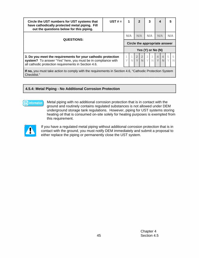
Circle the UST numbers for UST systems thathave cathodically protected metal piping. Fill
out the questions below for this piping.
UST # = 1 2 3 4 5
QUESTIONS:N/A N/A N/A N/A N/A
Circle the appropriate answer
Yes (Y) or No (N)
Chapter 4 Section 4.545
4.5.4: Metal Piping - No Additional Corrosion Protection
3. Do you meet the requirements for your cathodic protectionsystem? To answer “Yes” here, you must be in compliance withall cathodic protection requirements in Section 4.6.
1Y
1N
2Y
2N
3Y
3N
4Y
4N
5Y
5N
If no, you must take action to comply with the requirements in Section 4.6, “Cathodic Protection SystemChecklist.”
Metal piping with no additional corrosion protection that is in contact with theground and routinely contains regulated substances is not allowed under DEMunderground storage tank regulations. However, piping for UST systems storingheating oil that is consumed on-site solely for heating purposes is exempted fromthis requirement.
If you have a regulated metal piping without additional corrosion protection that is incontact with the ground, you must notify DEM immediately and submit a proposal toeither replace the piping or permanently close the UST system.

Chapter 4 Section 4.546
Make sure you read and complete the checklists in the appropriate corrosion protection forpiping sections for all of your piping that is in contact with the ground and routinely contains
regulated substances before answering the question below.
Summary of Compliance with Piping Corrosion Protection
Summary of Compliance with Piping Corrosion Protection
ANSWER THE FOLLOWING QUESTION: YES NO
Does all of your piping that is in contact with the ground and routinely containsregulated substances meet corrosion protection requirements?To answer YES here, you must be able to answer yes to all applicable previous questions for eachtype of piping at your facility.
List all of your tanks that have piping that does not meet the corrosion protectionrequirement.
Tank ID Substance
If you answered no, fill out a Return to Compliance Plan and submit it with your Certification of Compliance forms. A Return to Compliance Plan can be found in the accompanying Forms Booklet.

Chapter 4 Section 4.647
ExampleRectifierSample Impressed Current System Diagram
Section 4.6: Cathodic ProtectionIf your UST system contains fuel oil that is consumed on-site solely for heatingpurposes, you are not required to have cathodic protection
Cathodic protection is one option for meeting the corrosion protectionrequirements of metal UST components that are in contact with the ground androutinely contain regulated substances and are often buried. Components of
your UST system that may have cathodic protection include: metal tanks, piping, and ancillaryequipment such as turbine pump heads, flexible connectors, and swing joints.
Impressed Current Systems
An impressed current system uses a rectifier (an electrical device for converting alternatingcurrent into direct current) to provide direct current through anodes to the metal tank, piping, orother underground components to achieve corrosion protection. The diagram below illustratesimpressed current cathodic protection.
How to tell if you have an impressed current system: You should have an electrical rectifierlocated somewhere at your facility.
Galvanic (or Sacrificial) Anode Systems
A galvanic (or sacrificial) anode system uses anodes that are buried and attached to metal USTcomponents for corrosion protection. The anode is more electrically active and will sacrificeitself (corrode) to protect the metal component from corrosion. A sample picture of an anodeattached to a tank is shown on the next page.

Chapter 4 Section 4.648
Sample Galvanic (or sacrificial) anode
How to tell if you have a galvanic anodesystem: It is more difficult to tell if you have agalvanic anode system because you typicallycannot see the anodes and there is no rectifier. The anodes are attached to the undergroundcomponent they are protecting and are buried. These anodes are usually installed on tanks atthe factory (such as on the sti-P3® tank) and canbe installed on piping and other undergroundmetal components in the field. Ways to help youdetermine whether you have a galvanic systemare to look at any installation paperwork youmight have or to contact the contractor whoinstalled the UST and/or cathodic protectionsystem.
Requirements and Best Management Practices for Cathodic Protection
Your cathodic protection system must operate continuously to protect the metalcomponents of your UST system that are in direct contact with the ground.• If your cathodic protection system is disconnected or turned off, your
underground UST system components are not protected from corrosion.S Never turn off your rectifier.S Never disconnect a galvanic anode.
• Note that contractors may have to turn off or disconnect your cathodic protectionfor short periods during repairs.
All cathodic protection systems that are field-installed must be designed by acorrosion expert. Field-installed means that the cathodic protection system was notinstalled on the tank when the tank or piping was in the factory. An example of atank that has a factory installed cathodic protection system is the sti-P3® tank.
A corrosion expert must meet specific qualifications. That person must be either:1. Certified by NACE as a Corrosion Specialist or Cathodic Protection Specialist, or2. A registered Professional Engineer that has certification or licensing that includes
education and experience in corrosion control of buried or submerged metal pipingsystems and metal tanks.
A code of practice must be followed when adding a cathodic protection system toyour UST system.
You must have your cathodic protection system tested by a qualified cathodic protection tester within 6 months of installation and then at least every 2 years for animpressed system, and every 3 years for a sacrificial anode system. In addition, ifyou have any repairs conducted to your cathodically protected UST system, or if anymaintenance or construction in the area of the structure occurs, you must have acathodic protection test conducted within 6 months of that repair.

Chapter 4 Section 4.649
• You must keep all records of the operation, repair, and testing of the cathodicprotection system for 3 years beyond the operational life of the facility. A samplecathodic protection test record is provided for you in Appendix D.
• If your cathodic protection system does not pass the test, have your cathodicprotection system evaluated and fixed by a corrosion expert within 30 days and areport must be submitted to the DEM.
A cathodic protection tester is a person who can demonstrate an understanding of theprinciples of all common types of cathodic protection systems as applied to buried orsubmerged metal piping and tank systems.
If you have an impressed current cathodic protection system, you must inspect the rectifier at least every 60 days to make sure that it is on and operating properly. • You must keep all records of these checks for 3 years beyond the operational life
of the facility. A sample impressed current inspection record keeping form isprovided for you in Appendix E.
• If your rectifier is not operating within the normal values, contact a corrosionexpert to evaluate and fix your cathodic protection system within 30 days.
Keep all paperwork related to your cathodic protection system.
The person who installed your impressed current system should have provided you withpaperwork to indicate what the normal operating voltage and amperage values are for yourcathodic protection system. If you do not have values for the normal operating voltage andamperage, contact the person who installed the system and obtain that information. Recordthe amperage and voltage readings and compare them to the normal operating values duringeach inspection.
Have cathodic protection tests conducted more frequently. The more often you havethese tests conducted, the more likely you are to detect cathodic protection problemsbefore releases occur.
Perform inspections of your rectifier more frequently than the 60 day requirement. Themore often you inspect the rectifier, the quicker you can detect problems with yourcathodic protection system.

Chapter 4 Section 4.650
Cathodic Protection System Checklist
Circle the UST numbers that have cathodicprotection and answer the questions below.
UST # = 1 2 3 4 5
Note: If your buried tank and piping components do not havecathodic protection, then circle N/A (not applicable) for thatUST system. You do not need to answer questions for thatUST.
QUESTIONS
N/A N/A N/A N/A N/A
1. What type of cathodic protection system do you have for thetank of this UST system?(In the space provided, enter: IC for impressed current, GAL forgalvanic, BOTH for both impressed current and galvanic anodes)
2. What type of cathodic protection system do you have for thepiping of this UST system? (In the space provided, enter: IC for impressed current, GAL forgalvanic, BOTH for both impressed current and galvanic anodes)
3. Enter the date or dates of installation for your cathodicprotection system (mm/dd/yy).
4. Does your cathodic protection system operatecontinuously?
1Y
1N
2Y
2N
3Y
3N
4Y
4N
5Y
5N
Answer yes here if you never disconnect your galvanic (sacrificial) anodes and you never turn off yourrectifier or if the only time this occurs is for short periods when a contractor works on your cathodicprotection system.
If no, contact the DEM to determine how to return to compliance.
5. Was your cathodic protection system either designed by acorrosion expert or installed at the factory?
1Y
1N
2Y
2N
3Y
3N
4Y
4N
5Y
5N
If no, then to return to compliance: 1. Have a corrosion expert evaluate your existing cathodic protection system.2. If the design is not adequate, take the necessary steps to have your cathodic protection fixed.3. Keep a record of the evaluation and repairs.4. Contact the DEM to determine any further actions necessary to return to compliance.
6. Did you have your cathodic protection system tested within6 months of installation, at least every 2 years for animpressed current system, or 3 years for a sacrificial anodesystem, and within 6 months following any repairs to yourcathodically protected UST system, or within 6 months of anymaintenance or construction in the area of the UST system?
1Y
1N
2Y
2N
3Y
3N
4Y
4N
5Y
5N
If no, have a cathodic protection test conducted by a qualified cathodic protection tester as soon aspossible. Contact the DEM to determine any further actions necessary to return to compliance.

Circle the UST numbers that have cathodicprotection and answer the questions below.
UST # = 1 2 3 4 5
Note: If your buried tank and piping components do not havecathodic protection, then circle N/A (not applicable) for thatUST system. You do not need to answer questions for thatUST.
QUESTIONS
N/A N/A N/A N/A N/A
Chapter 4 Section 4.651
7. Do you have records of your cathodic protection tests?Answer yes here if one of the following apply:
1Y
1N
2Y
2N
3Y
3N
4Y
4N
5Y
5N
1. You have records of all cathodic protection tests as described in this section.2. You have no records and your cathodic protection system was installed less than 6 months ago.
Enter the date of your most recent test (mm/dd/yy).
If no, contact the person who performed your cathodic protection tests and obtain records of yourcathodic protection testing.
8. Did your most recent cathodic protection test pass? 1Y
1N
2Y
2N
3Y
3N
4Y
4N
5Y
5N
If no, have a corrosion expert evaluate your cathodic protection system and fix any problems as soonas possible. Also have a cathodic protection test conducted within 6 months of the repair and makesure the cathodic protection system passes the test.
Questions 9 - 11 are for cathodic protection systems with rectifiers only (Impressed CurrentSystems). Skip these questions if you only have galvanic (sacrificial) anodes.
9. Do you inspect your rectifier at least every 60 days? 1Y
1N
2Y
2N
3Y
3N
4Y
4N
5Y
5N
If no, begin inspecting your rectifier at least every 60 days by recording amperage and voltage readingson your rectifier and comparing those readings with the normal operating values.
10. Do you have records of your rectifier inspections? Answer yes here if one of the following apply:
1Y
1N
2Y
2N
3Y
3N
4Y
4N
5Y
5N
1. You have records of all the rectifier inspections that are required as described in this section. 2. You have at least 2 records and your cathodic protection system was installed less than 6 months ago.3. You have at least 1 record and your cathodic protection system was installed less than 4 months ago.4. You have no records yet and your cathodic protection system was installed less than 2 months ago.
Enter the date of your most recent inspection (mm/dd/yy).
If no, begin keeping records of your rectifier inspection.
11. Did your most recent cathodic protection inspection resultsfall within the amperage and voltage ranges established by thecorrosion expert? If you do not have voltage and amperageranges established by the corrosion expert, call the person whoinstalled your cathodic protection system and get those values
1Y
1N
2Y
2N
3Y
3N
4Y
4N
5Y
5N
If no, have a corrosion expert evaluate your cathodic protection system and fix any problems as soonas possible. Also have a cathodic protection test conducted within 6 months of the repair.

Chapter 4 Section 4.752
Section 4.7: Leak Detection for Tanks
If your UST system contains fuel oil that is consumed on-site solely for heatingpurposes, you are not required to have leak detection.
Leak detection (also called release detection) requirements for single-walled tanksinclude Automatic Tank Gauging (ATG), Tightness Testing, and InventoryControl. For tanks with secondary containment, or double-walled tanks, leakdetection requirements include Continuous Interstitial Monitoring and InventoryControl.
If you have a Waste Oil tank, then you must comply with one of the following leak detectionrequirements:
If the waste oil tank is single-walled and less than 2,000 gallons, you must conducteither:
1. Automatic tank gauging (0.2 gph monthly leak test required) and tanktightness testing at 5 year intervals, or if the tank has been installed for morethan 20 years, tank tightness testing every 2 years; or
2. Annual tank tightness testing and inventory control modified for a waste oiltank (See Section 4.7.5).
If the waste oil tank is single-walled and greater than 2,000 gallons, you mustconduct:
1. Automatic tank gauging (0.2 gph monthly leak test required) and tanktightness testing at 5 year intervals, or if the tank has been installed for morethan 20 years, tank tightness testing every 2 years.
If the waste oil tank is double-walled, you must have:
1. Continuous Interstitial Monitoring.
If you have a Diesel Generator UST, then you must comply with all of the leakdetection requirements for a diesel tank, except for inventory control. Dieselgenerator USTs are not required to conduct inventory control.
General Requirements and Best Management Practices for ALL Tank Leak DetectionMethods
You are required to test and conduct system checks on your leak detectionequipment.
The following tests are required to be conducted annually:C Automatic Tank Gauge System Test• Continuous Interstitial Monitoring System Test

Chapter 4 Section 4.753
C Tank Tightness Testing
The following tests/checks are required to be conducted monthly:C Automatic Tank Gauge System Check to ensure it is operating effectivelyC Automatic Tank Gauge System Leak TestC Reconcile your Inventory
You are required to record your inventory daily.
Your release detection must be installed, calibrated, operated, and maintainedaccording to the manufacturer’s instructions.
The following information/documentation must be kept for 3 years beyond the life ofthe facility:C annual leak detection device test resultsC tank tightness test resultsC all repair documentation
The following must be kept for 3 years:C maintenance/inventory records C strip chart and manual recordings for continuous monitoringC results of all monthly system checksC shear valve annual checks
If you ever suspect or confirm a release, you must take appropriate action and, ifnecessary, report the release. Refer to Section 4.9 for information on what to do.Never ignore leak detection alarms or failed leak detection tests. Treat themas suspected leaks!
If you have hazardous substance tanks (as defined under CERCLA), you must havedouble-walled tanks and use interstitial monitoring for release detection unless youhave obtained a waiver from the DEM.
All leak monitoring devices shall not be shut off or deactivated at any time except for repair; any deactivation must be reported to the DEM. All monitoring devices shallemploy an audible alarm and a visual indicator, which shall be located as to be heardand seen by the owner/operator or other personnel during normal working hours.
Keep all schedules of required calibration and maintenance provided by theequipment manufacturer.
Periodically have a qualified UST contractor, such as the vendor who installed yourrelease detection system, service all the system components according to themanufacturer’s service instructions.C Components can wear out and must be checked periodically. Many vendors
recommend or require this maintenance activity at least once annually.

Chapter 4 Section 4.754
Make sure your vendor or installer provides you with the information and trainingnecessary to make sure your release detection equipment works effectively to detectleaks. If you don’t know how your system works, you will fail inspections and mayfind yourself with violations and penalties. Worse, you may discover that you havehad a leak and may have to pay for extensive cleanup of a contaminated site and fordamages caused to others. It is your responsibility to know how to operate all yourrelease detection devices properly so that you meet regulatory requirements andprotect the environment.
Make sure employees who run, monitor, or maintain the release detection systemare aware of correct operating procedures. Develop and maintain regular trainingprograms for all employees.
To determine requirements and BMPs for release detection of your tank(s), do the following:
1. Identify the type(s) of release detection you use for your tanks. Check the appropriateboxes in the table below.
Different tanks at your facility may use different types of leak detection. Make sure to select the appropriate type of leak detection for each tank atyour facility.
You may have more than one type of leak detection for a tank at your facility. For the purposes of determining your compliance, you should check only themethod(s) of leak detection you are using to comply with the releasedetection for tanks portion of the UST regulations. If you use multiple typesof leak detection for a single tank, then you need to meet the requirementsfor each type of release detection you checked.
2. For each type of leak detection you checked, go to the appropriate section and read and fill out the appropriate checklist(s). You may need to go to more than one checklist – each leak detection type has a separate checklist.
If you have an UST system that contains a hazardous substance (one common example isantifreeze), check the last row of the table below for that UST.
What Type(s) Leak Detection Do You Use for Your Tank(s)? Go to these sections forinformation and
compliance checklistsUST Number: 1 2 3 4 5
Automatic Tank Gauging (ATG) Section 4.7.1Interstitial Monitoring for Double-Walled Tanks Section 4.7.2
Tank Tightness testing Section 4.7.3Inventory ControlInventory Control for a Waste Oil Tank
Section 4.7.4Section 4.7.5
Check here if your tank contains a hazardous substance Section 4.7.2
If your tank leak detection is not listed above, contact the DEM to determine what you must do.

Chapter 4 Section 4.755
Sample ATG Monitor Sample ATG Monitor
Sample Part of a Measuring Stick
If you know the type(s) of leak detection you have, skip the description informationbelow and proceed as instructed in the table above. Otherwise, take the followingsteps to figure out what is at your facility:
• Read the descriptions below of the different tank leak detection types. Look through your oldrecords to see if they match any of the names in the descriptions.
• Contact the contractor who installed your leak detection system.
Leak Detection Descriptions
Automatic Tank Gauging (ATG) - An ATG system consists of a probe permanently installed ina tank and wired to a monitor to provide information such as fuel level and temperature. Youshould have an ATG monitor mounted somewhere at your facility. ATG systems automaticallycalculate the changes in fuel volume that can indicate a leaking tank and can be set to alarmwhen there is a suspected problem with your tank.
Double-Walled Tanks with Interstitial Monitoring - Secondary containment is an additionalbarrier between the portion of an UST system that contains fuel and the outside environment.Secondary containment is provided by the outer tank wall of a double-walled system. Hazardous substance tanks must be double-walled with interstitial monitoring or youmust obtain a waiver from the DEM. The area between the inner and outer barriers is calledthe interstitial space (or annular space). You must have interstitial monitoring ports on thepavement at your facility. Electronic probes in the interstitial space are connected to andmonitored by electronic equipment (such as an automatic tank gauge).
Inventory Control - This method involves measuring the contents of the tank and recording theamount of fuel pumped each day and reconciling that data with measurements and records offuel delivery. Typically, a measuring stick or an ATG is used to take the measurements.

Chapter 4 Section 4.756
Sample ATG
4.7.1: Automatic Tank Gauging (ATG)
Tank Tightness Testing - This is a tank testing method that is capable of determining whetheror not an underground storage tank, line, or system is leaking, as defined by NFPA 329,“Handling Releases of Flammable and Combustible Liquids and Gases.” The test is capable ofaccurately detecting a tank or a tank and line leak of 0.1 gallons per hour, adjusted for allvariables, with a probability of detection of no less than 95 percent and a probability of falsedetection of no more than 5 percent. The test method must be approved by the DEM prior touse, follow the manufacturers protocol, and be conducted by persons who are licensed by theDEM.
ATG systems automatically calculate thechanges in fuel volume that can indicate aleaking tank. ATG is not required for tanksupgraded by lining or cathodic protectionfor the first 10 years after the upgrade.
Requirements and Best Management Practices for Automatic Tank Gauging (ATG)Systems
LEAK DETECTION TESTYou are required to use your ATG system to test for leaks at least once every Month.• Remember to test each tank.• Make sure you are properly testing the portion of the tank that routinely contains
regulated substances.• Make sure that the amount of fuel in your tank is sufficient to run the ATG leak
test. The tank must contain a minimum amount of fuel to perform a valid leakdetection test.T One source for determining that minimum amount is the performance
certification for your leak detection equipment.
SYSTEM CHECKYour ATG system is required to be tested on a monthly basis to ensure that they areoperating according to the manufacturers specifications.C Read your owner’s manual, run the appropriate tests, and see if your ATG
system is set up and working properly.C Most ATG systems have a “test” or “self-diagnosis” mode that may run these
checks.
All ATG systems must be inspected, calibrated, and tested annually by a qualifiedcontractor to insure proper operation.
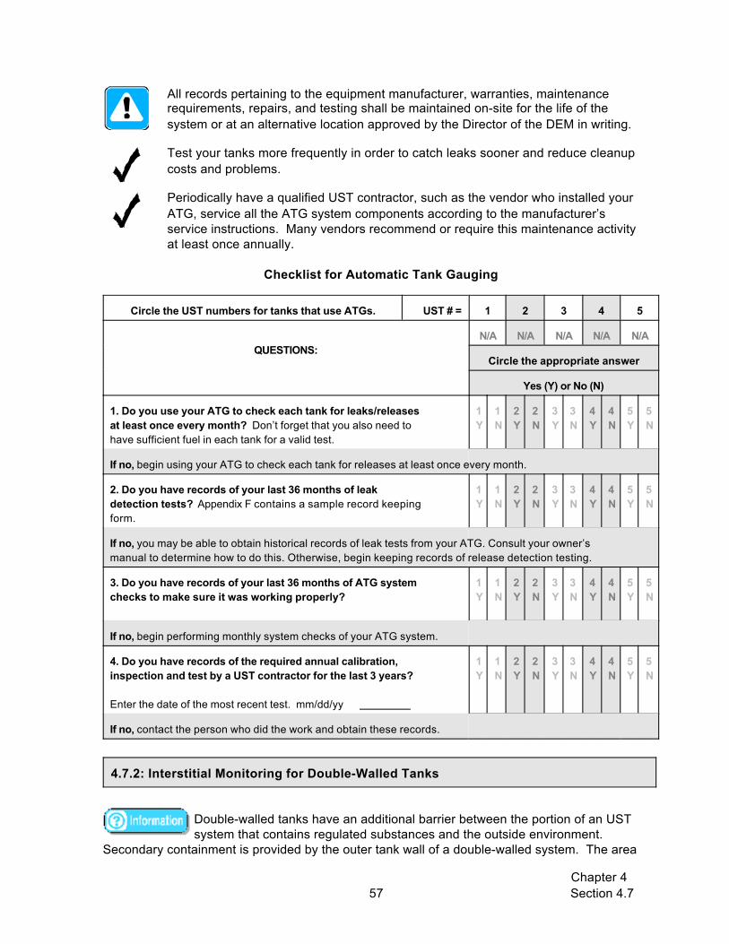
Chapter 4 Section 4.757
4.7.2: Interstitial Monitoring for Double-Walled Tanks
All records pertaining to the equipment manufacturer, warranties, maintenance requirements, repairs, and testing shall be maintained on-site for the life of thesystem or at an alternative location approved by the Director of the DEM in writing.
Test your tanks more frequently in order to catch leaks sooner and reduce cleanup costs and problems.
Periodically have a qualified UST contractor, such as the vendor who installed yourATG, service all the ATG system components according to the manufacturer’sservice instructions. Many vendors recommend or require this maintenance activityat least once annually.
Checklist for Automatic Tank Gauging
Circle the UST numbers for tanks that use ATGs. UST # = 1 2 3 4 5
QUESTIONS:N/A N/A N/A N/A N/A
Circle the appropriate answer
Yes (Y) or No (N)
1. Do you use your ATG to check each tank for leaks/releasesat least once every month? Don’t forget that you also need tohave sufficient fuel in each tank for a valid test.
1Y
1N
2Y
2N
3Y
3N
4Y
4N
5Y
5N
If no, begin using your ATG to check each tank for releases at least once every month.
2. Do you have records of your last 36 months of leakdetection tests? Appendix F contains a sample record keepingform.
1Y
1N
2Y
2N
3Y
3N
4Y
4N
5Y
5N
If no, you may be able to obtain historical records of leak tests from your ATG. Consult your owner’smanual to determine how to do this. Otherwise, begin keeping records of release detection testing.
3. Do you have records of your last 36 months of ATG systemchecks to make sure it was working properly?
1Y
1N
2Y
2N
3Y
3N
4Y
4N
5Y
5N
If no, begin performing monthly system checks of your ATG system.
4. Do you have records of the required annual calibration,inspection and test by a UST contractor for the last 3 years?
Enter the date of the most recent test. mm/dd/yy
1Y
1N
2Y
2N
3Y
3N
4Y
4N
5Y
5N
If no, contact the person who did the work and obtain these records.
Double-walled tanks have an additional barrier between the portion of an UST system that contains regulated substances and the outside environment.
Secondary containment is provided by the outer tank wall of a double-walled system. The area
Chapter 4 Section 4.758
between the inner and outer walls is called the interstitial space or annular space and can bemonitored to catch problems before regulated substances reach the environment. Hazardoussubstance tanks must be double-walled with interstitial monitoring or you must obtain awaiver from the DEM.
Interstitial monitoring systems must be designed, constructed, and installed to detect a leakfrom any part of the tank that routinely contains fuel. For double-walled tanks, the test methodmust be able to detect a release through the inner wall of the double-walled tank.
Requirements and Best Management Practices for Double-Walled Tanks with InterstitialMonitoring
All leak monitoring devices shall not be shut off or deactivated at any time except forrepair and must be reported to the DEM. All monitoring devices shall employ anaudible alarm and a visual indicator, which shall be located as to be heard and seenby the owner/operator or other personnel during normal working hours.
SYSTEM CHECKTest your interstitial monitoring system monthly to ensure it is operating effectively.C Read your owner’s manual, run the appropriate tests, and see if your interstitial
monitoring system is set up and working properly.C Most interstitial monitoring systems have a “test” or “self diagnosis” mode that
may run these checks.
Have a qualified UST contractor inspect, calibrate, and test your interstitial monitoringsystem annually.
You should frequently test your interstitial monitoring system to make sure it isworking properly.
Periodically have a qualified UST contractor, such as the vendor who installed yourelectronic interstitial monitoring system, service all the system componentsaccording to the manufacturer’s service instructions.
Testing more often than monthly can catch leaks sooner and reduce cleanup costsand problems.

Chapter 4 Section 4.759
4.7.3: Tank Tightness Testing
Checklist for Interstitial Monitoring of Double-Walled Tanks
Circle the UST numbers for tanks that useinterstitial monitoring.
UST # = 1 2 3 4 5
QUESTIONS:N/A N/A N/A N/A N/A
Circle the appropriate answer
Yes (Y) or No (N)
1. Do you continuously use interstitial monitoring to checkeach tank for leaks/releases.
1Y
1N
2Y
2N
3Y
3N
4Y
4N
5Y
5N
If no, contact the DEM to determine how to return to compliance.
2. Do you have records of monthly interstitial monitoringsystem checks for the past 36 months? Appendix F contains a sample record keeping form.
1Y
1N
2Y
2N
3Y
3N
4Y
4N
5Y
5N
If no, begin conducting monthly checks of your interstitial monitoring system and maintain records ofthese checks.
3. Do you have all records of maintenance, and repair of yourinterstitial monitoring system conducted in the last 3 years?
1Y
1N
2Y
2N
3Y
3N
4Y
4N
5Y
5N
If no, contact the person who did the work and obtain the records.
4. Do you have records of the required annual inspection,calibration, and test by a UST contractor for the last 3 years?
Enter the date of the most recent test. MM/DD/YY
1Y
1N
2Y
2N
3Y
3N
4Y
4N
5Y
5N
If no, contact the person who did the testing and obtain the records.
Requirements and Best Management Practices for Tank Tightness Testing
You must perform tank tightness tests on all single-walled tanks.
If you have a waste oil tank less than 2,000 gallons and without an Automatic TankGauge installed, you are required to tightness test your tank annually.
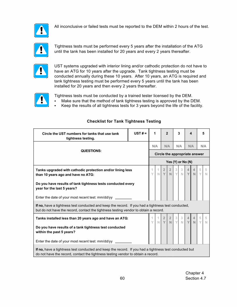
Chapter 4 Section 4.760
All inconclusive or failed tests must be reported to the DEM within 2 hours of the test.
Tightness tests must be performed every 5 years after the installation of the ATG until the tank has been installed for 20 years and every 2 years thereafter.
UST systems upgraded with interior lining and/or cathodic protection do not have tohave an ATG for 10 years after the upgrade. Tank tightness testing must beconducted annually during these 10 years. After 10 years, an ATG is required andtank tightness testing must be performed every 5 years until the tank has beeninstalled for 20 years and then every 2 years thereafter.
Tightness tests must be conducted by a trained tester licensed by the DEM. C Make sure that the method of tank tightness testing is approved by the DEM.C Keep the results of all tightness tests for 3 years beyond the life of the facility.
Checklist for Tank Tightness Testing
Circle the UST numbers for tanks that use tanktightness testing.
UST # = 1 2 3 4 5
QUESTIONS:N/A N/A N/A N/A N/A
Circle the appropriate answer
Yes (Y) or No (N)
Tanks upgraded with cathodic protection and/or lining lessthan 10 years ago and have no ATG:
Do you have results of tank tightness tests conducted everyyear for the last 5 years?
Enter the date of your most recent test: mm/dd/yy
1Y
1N
2Y
2N
3Y
3N
4Y
4N
5Y
5N
If no, have a tightness test conducted and keep the record. If you had a tightness test conducted,but do not have the record, contact the tightness testing vendor to obtain a record.
Tanks installed less than 20 years ago and have an ATG:
Do you have results of a tank tightness test conductedwithin the past 5 years?
Enter the date of your most recent test: mm/dd/yy
1Y
1N
2Y
2N
3Y
3N
4Y
4N
5Y
5N
If no, have a tightness test conducted and keep the record. If you had a tightness test conducted butdo not have the record, contact the tightness testing vendor to obtain a record.
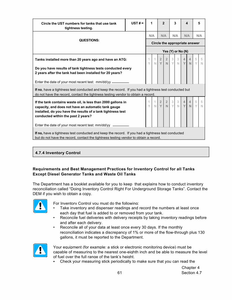
Circle the UST numbers for tanks that use tanktightness testing.
UST # = 1 2 3 4 5
QUESTIONS:N/A N/A N/A N/A N/A
Circle the appropriate answer
Yes (Y) or No (N)
Chapter 4 Section 4.761
4.7.4 Inventory Control
Tanks installed more than 20 years ago and have an ATG:
Do you have results of tank tightness tests conducted every2 years after the tank had been installed for 20 years?
Enter the date of your most recent test: mm/dd/yy
1Y
1N
2Y
2N
3Y
3N
4Y
4N
5Y
5N
If no, have a tightness test conducted and keep the record. If you had a tightness test conducted butdo not have the record, contact the tightness testing vendor to obtain a record.
If the tank contains waste oil, is less than 2000 gallons incapacity, and does not have an automatic tank gaugeinstalled, do you have the results of a tank tightness testconducted within the past 2 years?
Enter the date of your most recent test: mm/dd/yy
1Y
1N
2Y
2N
3Y
3N
4Y
4N
5Y
5N
If no, have a tightness test conducted and keep the record. If you had a tightness test conductedbut do not have the record, contact the tightness testing vendor to obtain a record.
Requirements and Best Management Practices for Inventory Control for all TanksExcept Diesel Generator Tanks and Waste Oil Tanks
The Department has a booklet available for you to keep that explains how to conduct inventoryreconciliation called “Doing Inventory Control Right For Underground Storage Tanks”. Contact theDEM if you wish to obtain a copy.
For Inventory Control you must do the following:• Take inventory and dispenser readings and record the numbers at least once
each day that fuel is added to or removed from your tank. • Reconcile fuel deliveries with delivery receipts by taking inventory readings before
and after each delivery. • Reconcile all of your data at least once every 30 days. If the monthly
reconciliation indicates a discrepancy of 1% or more of the flow-through plus 130gallons, it must be reported to the Department.
Your equipment (for example: a stick or electronic monitoring device) must becapable of measuring to the nearest one-eighth inch and be able to measure the levelof fuel over the full range of the tank’s height.C Check your measuring stick periodically to make sure that you can read the

Chapter 4 Section 4.762
markings and numbers and that the bottom of the stick is not worn.
You must measure the water in your tank to the nearest one-eighth inch at least onceper month.C You can use a paste that changes color when it comes into contact with water.
You must ensure that your fuel dispensers are calibrated according to localstandards or to an accuracy of 6 cubic inches for every 5 gallons of fuel withdrawn.C Look on your dispenser for a weights and measures sticker or contact your local
department of weights and measures.
Circle the UST numbers for tanks that useinventory control.
UST # = 1 2 3 4 5
QUESTIONS:N/A N/A N/A N/A N/A
Circle the appropriateanswer
Yes (Y) or No (N)
1. Do you perform inventory control properly? Appendix Gcontains sample inventory worksheets. A sample manual tankgauging record can be found in Appendix H.
1Y
1N
2Y
2N
3Y
3N
4Y
4N
5Y
5N
This includes: 1. Taking inventory and dispenser readings at least once each day that fuel is addedto or removed from your tank.2. Reconciling fuel deliveries with delivery receipts by taking inventory readings beforeand after each delivery.3. Reconciling all of your data at least once every 30 days.4. Calculation of 1% flow- through plus 130 gallons.
If no, begin performing proper inventory control.
2. Do you have records for, at minimum, the last 36 monthsof inventory control (including water measurements)? Asample inventory control worksheet is provided in Appendix G.
1Y
1N
2Y
2N
3Y
3N
4Y
4N
5Y
5N
If no, begin keeping records of inventory control and water measurements.
3. Is the measuring equipment used capable of measuringto the nearest one-eighth inch over the entire height of thetank?
1Y
1N
2Y
2N
3Y
3N
4Y
4N
5Y
5N
If no, get equipment (for example, a stick) that meets these requirements.
4. Do you measure the water in each of your tanks at leastonce every 30 days to the nearest one-eighth inch?
1Y
1N
2Y
2N
3Y
3N
4Y
4N
5Y
5N
If no, begin taking water readings of each tank at least once every 30 days.
Chapter 4 Section 4.763
4.7.5 Inventory Control for Single-Walled Waste Oil Tanks Less Than 2,000 Gallons
Requirements and Best Management Practices for Inventory Control for single-walledWaste Oil Tanks 2,000 gallons or less
The Department has a booklet available for you to keep that explains how to conduct inventoryreconciliation for waste oil tanks. Contact the DEM if you wish to obtain a copy.
For Inventory Control for single-walled waste oil tanks 2,000 gallons or less, youmust do the following:C Once each week, take the tank out of service for 36 hours and perform liquid level
measurements before and after this period. The difference in volume must be 10gallons or less for tanks up to 550 gallons, 13 gallons or less for tanks between551 and 1,000 gallons, and 26 gallons or less for tanks between 1,001 and 2,000gallons.
C Once a month, average the four weekly changes in tank volume (taking intoconsideration positive and negative numbers). This average is required to be 5gallons or less for tanks up to 550 gallons, 7 gallons or less for tanks between551 and 1,000 gallons, and 13 gallons or less for tanks between 1,001 and 2,000gallons.
C If any weekly or monthly change exceeds the allowable amount, then a leak issuspected and the Department must be contacted immediately.
Your stick must be capable of measuring to the nearest one-eighth inch and be ableto measure the level of fuel over the full range of the tank’s height.C Check your measuring stick periodically to make sure that you can read the
markings and numbers and that the bottom of the stick is not worn.
You must measure the water in your tank to the nearest one-eighth inch at least onceper month.C You can use a paste that changes color when it comes into contact with water.

Chapter 4 Section 4.764
Checklist for Inventory Control for Single-Walled Waste Oil Tanks that are 2,000 gallonsor less
Circle the UST number of the waste oil tank using inventory control.
UST # = 1 2 3 4 5
QUESTIONS:N/A N/A N/A N/A N/A
Circle the appropriateanswer
Yes (Y) or No (N)
1. Do you perform inventory control properly? Appendix Gcontains a sample inventory control worksheet. A sample manualtank gauging record can be found in Appendix H.
1Y
1N
2Y
2N
3Y
3N
4Y
4N
5Y
5N
This includes: 1. Once a week take tank out of service for 36 hours.2. Take liquid measurements before and after the 36 hour shut down.
3. Reconciling your 4 weeks of data once every 30 days.
If no, begin performing proper inventory control.
2. Do you have records for, at minimum, the last 36 monthsof inventory control (including water measurements)? Asample inventory control worksheet is provided in Appendix G.
1Y
1N
2Y
2N
3Y
3N
4Y
4N
5Y
5N
If no, begin keeping records of inventory control and water measurements.
3. Is the measuring equipment capable of measuring to thenearest one-eighth inch over the entire height of the tank?
1Y
1N
2Y
2N
3Y
3N
4Y
4N
5Y
5N
If no, get equipment (for example, a stick) that meets these requirements.
4. Do you measure the water in each of your tanks at leastonce every 30 days to the nearest one-eighth inch?
1Y
1N
2Y
2N
3Y
3N
4Y
4N
5Y
5N
If no, begin taking water readings of each tank at least once every 30 days.

Chapter 4 Section 4.765
Make sure you read and complete the checklists in the appropriate release detection sectionsfor all of your tanks before answering the questions below.
Summary of Compliance with Release Detection for Tanks
Summary of Compliance with Release Detection for Tanks
ANSWER THE FOLLOWING QUESTION: YES NO
1. Are all of your tanks in compliance with release detection requirements?To answer YES here, you must be able to answer yes to all applicable questions foreach type of tank release detection at your facility. If you have a hazardoussubstance tank please read the information below this question.
List all tanks that do not meet Release Detection requirements.
Tank ID Substance
If you answered no, fill out a Return to Compliance plan and submit it with your certification ofcompliance. A Return to Compliance plan can be found in the accompanying forms booklet.
If you have tanks that contain a hazardous substance listed on the CERCLA list ofhazardous substances (an example would be a tank that contains antifreeze), you mustmeet one of the following for each of these tanks:
1. You must have a double-walled tank with interstitial monitoring (see Section 4.7.2)
or
2. You must have a waiver from the DEM.

Chapter 4 Section 4.866
Section 4.8: Leak Detection for PipingIf your UST system contains fuel oil that is consumed on-site solely for heating purposesyou are not required to have leak protection for your piping.
There are pressurized, suction, and gravity piping delivery systems for pipingthat could be used with USTs. In addition, piping could either be above orbelow ground and either single or double walled. There are line leakdetection requirements for underground pressurized and suction piping. Theleak detection requirements are different depending on the type of pipingdelivery system. Do not include fill pipes as part of your piping.
To determine requirements and BMPs for leak detection of your piping, do the following:
1. Identify the type(s) of piping you have at your facility. Check the appropriate boxes in the table below.
Different piping runs at your facility may use different types of fuel deliverysystems. Make sure to select the appropriate type of fuel delivery system foreach piping run at your facility.
Note: If all piping associated with an UST system is aboveground, then thatpiping has no requirements for leak detection.
2. For each type of piping you check in the table below, go to the appropriate section andread and fill out the appropriate checklist(s) for piping release detection. You may needto go to more than one checklist.
What Type(s) of Piping Do You Have at Your Facility? Go to these sections forinformation and
compliance checklistsUST Number: 1 2 3 4 5
Pressurized (with some piping underground) Section 4.8.1Suction (with some piping underground) Section 4.8.2Gravity (with some piping underground) No RequirementsNo Underground Piping No RequirementsNo Piping No Requirements
If you do not know the type(s) of piping you have, take the following steps to figure outwhat is at your facility:• Read the descriptions below of the different types of fuel delivery systems for piping.• Look through your old records to see if they match any of the names in the descriptions.• Contact the contractor who installed your piping system.• Contact your service contractor/environmental consultant for assistance.
Fuel Delivery System Descriptions

Chapter 4 Section 4.867
Sample STP Head in aSump on Top of a Tank
Sample STP Head in a Sump on Top of a Tank
Sample Lid and Sump Cover
Example of a Suction PumpInside a Dispenser
Pressurized fuel delivery pushes fuel from the tank to the dispenser through piping by using asubmersible turbine pump (STP) located inside the tank. Usually there is a STP head in a sumpabove the tank. These sumps are often covered with a lid and may also have a sump coverunder the lid.
Suction fuel delivery pulls fuel from the tank to thedispenser through the piping by using a suction pumplocated at the dispenser. You should be able to tell if youhave suction piping by looking for a suction pump (you maysee pulleys and belts) inside the dispenser. Also, there willnot be a pump in a sump above the tank.
Gravity feed fuel delivery has no pump and relies on thedownward slope of the piping to transport fuel from the tankto the dispenser.
Chapter 4 Section 4.868
4.8.1 Leak Detection: Pressurized Piping
Each pressurized piping run must have an automatic Line Leak Detector (LLD)installed. You must meet specific requirements for your LLDs. See Section 4.8.1.1.
Along with a LLD, each pressurized piping must have one of the following:
• interstitial monitoring - to use this method, your piping must be double-walledand you must be monitoring the interstitial space continuously for releases. Ifyou have a hazardous substance UST system, you must either use interstitialmonitoring or have a waiver from the DEM.
• annual line tightness test - If you have single-walled piping, you must have aline tightness test conducted at least annually. See Section 4.8.3 forinformation and checklists for line tightness testing.
Contact the DEM if you do not use one of these methods.
If you have interstitial monitoring (Section 4.7.2), the requirements are the same forboth tanks and piping. In addition, you must ensure the following for interstitialmonitoring for piping:
• Sensors are typically located in the piping collection sump areas for interstitialmonitoring. These sumps must be tight and free of leaks for piping interstitialmonitoring to operate correctly.T Piping should slope to the sump containing the monitoring probe.T Check to see that sensors are located near the bottom of the sump so that
they activate quickly when a release occurs. T Sensors must be at least 1 inch below the lowest penetration fitting in the
sump.
Pressurized piping must be equipped with an emergency shut-off valve designed toclose automatically in the event of impact or fire exposure. The automatic closingfeature of the valve must be checked yearly by manually tripping the hold-openlinkage. Records must be kept of this inspection check.

Chapter 4 Section 4.869
Checklist for Pressurized Piping Leak Detection
Circle the UST numbers for pressurized piping. UST # = 1 2 3 4 5
Note: If you have an UST system with suction piping, gravity feedpiping, above-ground piping, or no piping, circle N/A here for thatUST.
Questions:
N/A N/A N/A N/A N/A
Circle the appropriate answer
Yes (Y) or No (N)
1. Do you have a LLD on each pressurized piping run?If you answer no here, skip Question 2.
1Y
1N
2Y
2N
3Y
3N
4Y
4N
5Y
5N
If no, have a contractor install a LLD for your piping.
2. Does your LLD meet the regulatory requirements?Read and fill out the checklist in Section 4.8.1.1 before answering thisquestion.
1Y
1N
2Y
2N
3Y
3N
4Y
4N
5Y
5N
If no, have a contractor fix or replace your LLD so that it meets the requirements in Section 4.8.1.1.
3. In addition to your LLD, what is the second method of leakdetection you use for your pressurized piping?
Use these abbreviations for this question:IM = interstitial monitoring (double-walled) LTT = line tightness testing (single-walled)
4. Do you meet the leak detection requirements for your secondmethod of leak detection for your pressurized piping?
1Y
1N
2Y
2N
3Y
3N
4Y
4N
5Y
5N
If you use:Piping interstitial monitoring - to answer yes here, your piping must be double-walled, your sumps must beleak-free, the piping should slope toward sumps containing the sensors, your sensors should be located nearthe bottom of your sumps, and you must meet the interstitial monitoring requirements in Section 4.7.2.Line tightness testing - to answer yes here, your piping must be single-walled, and you must meet thetightness testing requirements for pressurized piping. Fill out the checklist in Section 4.8.3 to make thisdetermination.
If no, take action to meet all of the release detection requirements for the release detection method you are usingor begin performing a method of release detection that meets the regulatory requirements.
5. Did you test the shear/crash/impact valve?
Enter the date this test was conducted: mm/dd/yy
1Y
1N
2Y
2N
3Y
3N
4Y
4N
5Y
5N
If no, take action to conduct the test.

Chapter 4 Section 4.870
Sample LLD
Sample STP Head withLLD
4.8.1.1 Leak Detection: Automatic Line Leak Detectors (LLDs)
Automatic LLDs are devices installed in thepiping run and are designed to detect acatastrophic release from pressurized piping. Typically, they are located on the submersibleturbine pump (STP) head in the sump aboveyour tank.
There are two types of automatic LLDs:
• Mechanical LLDs are mechanically operatedpressure valves that test for piping leakseach time the pump is turned on.
• Electronic LLDs have an electronic detectionelement that connects to an electronic control panel (such as an ATGsystem) and continuously monitors for piping releases.
Note: An electronic LLD may also be capable of conducting a line tightness test. Check with theDEM to see if this option applies to you.
Pressurized piping must have a LLD installed that can detect a release of 3 gallonsper hour at a line pressure of 10 pounds per square inch within one hour.
When a leak is detected, automatic LLDs must either:• shut off fuel flow;• restrict fuel flow; or• trigger an audible and visual alarm.
You must test each LLD at least once every year. The test must be performedaccording to the manufacturer’s requirements and procedures by trained, qualifiedpersonnel.• You must keep records of these annual tests for 3 years beyond the operational
life of the facility.
You must maintain all records of maintenance or repair to your LLD for a period of 3years beyond the operational life of the facility.
Frequently test your automatic LLDs according to the manufacturer’s instructions tomake sure they are working properly.
Make sure that your LLD is designed to operate with the type of fuel your USTsystem stores. For example, some LLDs are designed to work with gasoline, whileothers are intended to work with diesel.

Chapter 4 Section 4.871
Checklist for Automatic Line Leak Detectors
Circle the UST numbers for piping with a LLD. UST # = 1 2 3 4 5
Questions: N/A N/A N/A N/A N/A
Circle the appropriate answer
Yes (Y) or No (N)
1. Do you have a record indicating that your LLD has been tested annually?
1Y
1N
2Y
2N
3Y
3N
4Y
4N
5Y
5N
Enter the date of your most recent test (mm/dd/yy).
If no, either find the records, obtain the records from the person who conducted the tests, or have a testconducted. If a test is conducted, make sure each LLD passes the test and keep records of the resultsfor 3 years beyond the operational life of the facility.If a LLD fails a functionality test, have a trained person repair or replace the LLD.
2. Do you have all records of any maintenance, or repair ofyour LLD?
1Y
1N
2Y
2N
3Y
3N
4Y
4N
5Y
5N
If no, contact the person who did the work and obtain these records.
4.8.2 Leak Detection: Suction Piping
If you have suction piping, you must use one of the following leak detection methodsfor each piping run:
Double-Walled Suction Piping• Interstitial monitoring - You must be monitoring the interstitial space
continuously for releases. If you have a hazardous substance UST system,you must either use interstitial monitoring or have a waiver from the DEM.
Single-Walled Suction Piping• Line tightness test - You must have a line tightness test conducted at 5, 8, 11,
and 13 years after installation and annually thereafter. This method is describedin Section 4.8.3.
Contact the DEM if you do not use one of these methods.
If you have interstitial monitoring (Section 4.7.2), the requirements are the same for bothtanks and piping. In addition, you must ensure the following for interstitialmonitoring for piping:• Sensors are typically located in the piping collection sump areas for interstitial
monitoring. These sumps must be tight and free of leaks for piping interstitialmonitoring to operate correctly.T Piping should slope to the sump containing the monitoring probe.T Check to see that probes are located 1 inch below the lowest penetration
fitting or entry boot so that they activate quickly when a release occurs. T Secondary piping test boot must be disconnected.

Chapter 4 Section 4.872
Suction piping systems must be equipped with a check valve located underneath thedispensing unit or at the tank.
Checklist for Suction Piping Leak Detection
Circle the UST numbers for suction piping. UST # = 1 2 3 4 5
Note: If you have an UST system with pressurized piping or nopiping, circle N/A here for that UST.
Questions:
N/A N/A N/A N/A N/A
Circle the appropriate answer
Yes (Y) or No (N)
1. What method of leak detection do you use for your suctionpiping?
Use these abbreviations for this question:IM = interstitial monitoring (double-walled) LTT = line tightness testing (single-walled)
2. Do you meet the leak detection requirements for yoursuction piping?
1Y
1N
2Y
2N
3Y
3N
4Y
4N
5Y
5N
If you use:Piping interstitial monitoring - to answer yes here, your sumps must be leak-free, the pipingneeds to slope toward sumps containing the sensors, your sensors must be located 1 inch belowthe lowest fitting, and you must meet the interstitial monitoring requirements in Section 4.7.2.Line tightness testing - to answer yes here, you must meet the tightness testing requirements forsuction piping. Fill out the checklist in Section 4.8.3 to make this determination.
If no, begin performing a method of release detection that meets the requirements for that releasedetection method.
3. Do you have a check valve under the dispensing unit? 1Y
1N
2Y
2N
3Y
3N
4Y
4N
5Y
5N
If no, contact the DEM to determine how you may return to compliance.

Chapter 4 Section 4.873
4.8.3 Leak Detection: Line Tightness Testing
A periodic line tightness test must be used to meet leak detectionrequirements for your single-walled piping. Line tightness testing may beperformed by either a trained tester or by using a permanently installedelectronic system. Line tightness testing must be able to detect a 0.1 gallonper hour leak rate at 1.5 times the operating pressure of the piping.
You must keep results of tightness testing for 3 years beyond the operational life of the facility.
• For pressurized piping, testing is required every 12 months.• For suction piping, testing is required at 5, 8, 11, and 13 years after installation
and annually thereafter.
If you use a permanently installed electronic system, it must be inspected, calibrated,and tested on a yearly basis. You must keep records of these annual tests.
Tightness tests must be conducted by a trained tester licensed by the DEM. • Make sure that the method of tightness testing is approved by the DEM.C Keep the results of all tightness tests for 3 years beyond the life of the facility.
If you use a permanently installed electronic system, periodically have a trainedcontractor, such as the vendor who installed the system, service that systemaccording to the manufacturer’s instructions.
Checklist for Line Tightness Testing
Circle the UST numbers for piping that uses linetightness testing.
UST # = 1 2 3 4 5
Questions: N/A N/A N/A N/A N/A
Circle the appropriate answer
Yes (Y) or No (N)
1a. Do you have a record of a passing test for your mostrecent line tightness test?
1Y
1N
2Y
2N
3Y
3N
4Y
4N
5Y
5N
If no, either find the record, obtain the record from the person who conducted the test, or have a test conducted.
Enter the date of most recent test: mm/dd/yy

Circle the UST numbers for piping that uses linetightness testing.
UST # = 1 2 3 4 5
Questions: N/A N/A N/A N/A N/A
Circle the appropriate answer
Yes (Y) or No (N)
Chapter 4 Section 4.874
1b. Was your last tightness test conducted less than 1 yearago for pressurized piping or 5, 8, 11, 13 years afterinstallation and annually thereafter for suction piping?
1Y
1N
2Y
2N
3Y
3N
4Y
4N
5Y
5N
If no, have a tightness test conducted, make sure each piping run passes the test, and keep records of tightnesstesting.If a tightness test ever fails, your piping may be leaking. Report the problem to the DEM and take action to fixthe problem.
2. What type of piping do you have for your tanks? 1 2 3 4 5
Use these abbreviations for this question: PR = Pressurized piping SU = Suction piping
Summary of Compliance with Piping Leak Detection
Summary of Compliance with Piping Leak Detection
ANSWER THE FOLLOWING QUESTION: YES NO
1. Does all of your underground piping meet Leak detection requirements?To answer YES here, you must be able to answer yes to all applicable questions foreach type of piping at your facility. If you have piping that contains a hazardoussubstance read the information below this question.
If you answered no, fill out a Return to Compliance Plan and submit it with your Certification of Complianceforms. A Return to Compliance Plan can be found in the accompanying Forms Booklet.
If you have piping that contains a hazardous substance listed on the CERCLA list ofhazardous substances (an example would be a tank that contains antifreeze), you mustmeet one of the following for each of these piping runs:
1. You must have secondarily contained piping with interstitial monitoring. This is necessary forboth pressurized and suction piping,
or
2. You must have a waiver from the DEM.

Chapter 4 Section 4.975
Section 4.9: What to Do for Suspected or Confirmed Releases
Personnel at your facility should be fully prepared to respond to releases beforethey may occur. In addition, everyone needs to know what to do when releasedetection methods indicate a suspected or confirmed release.
You must respond to and report suspected or confirmed releases when they occur. If you think you may have a release or your release detection indicates a suspectedrelease, you need to take the following steps, as appropriate. Never ignore leakdetection alarms or failed leak detection tests; treat them as suspected leaks.
Step 1. Stop the Release
• Take immediate action to prevent the release of more fuel. • Turn off the power to the dispenser and “bag” the nozzle. • Make sure you know where your emergency shutoff switch is located. • If necessary, empty the tank, without further contaminating the site. You may need the
assistance of your supplier or distributor.
Step 2. Call For Help
Contact your local fire or emergency response authority. Make sure you have these crucialtelephone numbers prominently posted where you and your employees can easily see them.
Step 3. Contain the Spill or Overfill
Contain, absorb, and clean up any surface spills or overfills. You should keep enough absorbentmaterial at your facility to contain a spill or overfill of regulated substances until emergencyresponse personnel can respond to the incident.
The suggested supplies include, but are not limited to, the following:
• Containment devices, such as containment booms, dikes, and pillows• Absorbent material, such as kitty litter, chopped corn cob, sand, and sawdust. Be sure you
properly dispose of used absorbent materials• Mats or other material capable of keeping spill or overfill out of nearby storm drains• Spark-free flash light• Spark-free shovel• Buckets• Reels of “caution tape,” traffic cones, and warning signs• Personal protective and safety gear

Chapter 4 Section 4.976
Step 4. Identify Any Hazards
Identify any fire, explosion, or vapor hazards and take action to neutralize these hazards.
Step 5. Report to Authorities
All persons shall immediately report all confirmed and suspected leaks or releases from USTsystems to:
• The appropriate local fire official• The DEM at (401) 222-2797• The DEM 24 hour Emergency Response Hotline at (401) 222-3070• The local public water supplier in the event that a spill occurs in a public supply watershed
or in a wellhead protection area for community water supply wells.
Keep a list of emergency contacts and make sure everyone at your UST facility isfamiliar with the list of contacts. Appendix C contains a blank list for names andphone numbers of important contacts. Fill out this information for your facility sothat you will know who to call in the event of an emergency. Remove this page fromthe manual, copy it, fill it out, and post it in a prominent place at your facility.
Summary of Compliance with Suspected or Confirmed Releases
ANSWER THE FOLLOWING QUESTIONS: YES NO
Did you appropriately respond to and report all suspected or confirmedreleases? This includes responding to a suspected problem due to a failed releasedetection result. If you did not have a release, answer YES to this question.
If you answered no, fill out a Return to Compliance Plan and submit it with your Certification of Compliance forms.A Return to Compliance Plan can be found in the accompanying Forms Booklet.

Chapter 4 Section 4.1077
Financial Responsibility: Mechanisms
Directions for Completing the Financial Responsibility Section.
Step 1. Read this section to determine the requirements you must meet for FR.
Step 2. Complete the checklist for FR for your facility.
Step 3. Complete the “Summary of Compliance with Financial Responsibility Requirements” question on the bottom of the last page of this section.
Section 4.10: Financial ResponsibilityTo be in compliance, you must demonstrate financial responsibility (FR) – theability to pay for cleanup or third-party liability compensation – for all of yourregulated underground storage tank systems that store petroleum with thefollowing exceptions.
These tanks do not require FR:C Tanks storing fuel that is consumed on-site solely for heatingC Farm and residential tanks of 1,100 gallons or less capacity storing motor fuel which is not
for resaleC Tanks storing fuel used solely by emergency power generatorsC Tanks storing hazardous waste, including waste oilC Airport hydrant fueling systemsC Tanks owned by state or federal government entities whose debts and liabilities are the
debts and liabilities of a state or the United States
This section provides a general explanation of the FR requirements. For detailed information onFR, see the Office of Underground Storage Tank’s web site athttp://www.epa.gov/swerust1/ustsystm/finresp.htm.
Requirements for Financial Responsibility
You must have the appropriate FR mechanism(s),• amount of coverage,• scope of coverage, and• certification.
Each of these components is discussed on the pages that follow.
Chapter 4 Section 4.1078
You must have an appropriate FR mechanism at your facility. The followingmechanisms may be used to comply with the FR requirements. You may use one or a combination of these mechanisms:
A. The Rhode Island Underground Storage Tank Financial Responsibility Fund is amechanism for demonstrating FR for UST systems subject to FR requirements. TheFund operates as a reimbursement program for expenses related to environmentalcleanup and third party compensation costs. To be eligible, facilities must be incompliance with the UST regulations and must incur a $20,000 deductible expense. Formore information, see the Fund’s website as www.riustreviewboard.org.
B. A financial test of self-insurance - A firm with a tangible net worth of at least$10 million may demonstrate FR by passing one of the two financial tests listed in thefederal regulations.
C. A corporate guarantee - You may secure a corporate guarantee from another eligiblefirm. The provider of the guarantee has to pass one of the financial tests listed in theregulations.
D. Insurance coverage - You may buy insurance from an insurer or a risk retention group.E. A surety bond - You may obtain surety bond, which is a guarantee by a surety
company that it will satisfy FR obligations if the owner or operator does not.F. A letter of credit - You may obtain a letter of credit, which obligates the issuer to
provide funding for corrective action and third-party compensation.G. A trust fund - You may set up a fully-funded trust fund administered by a third-party to
pay for corrective action and third-party compensation.H. Other DEM authorized methods - You may use additional methods of coverage
(e.g., certificate of deposit) authorized in Rhode Island. Contact the DEM USTprogram to find out if this can apply to you.
If you are a local government, there are four additional compliance methods that you can use tocomply with the FR requirements:
I. A bond rating test - A local government may demonstrate (or guarantee) FR bypassing a bond rating test.
J. A financial test - A local government may demonstrate (or guarantee) FR by passing afinancial test.
K. A guarantee - A local government may obtain a guarantee from another localgovernment or the state.
L. A dedicated fund - A local government may demonstrate (or guarantee) FR byestablishing a fund.
You may also use one or a combination of mechanisms to meet your FR obligations.Combinations may be used to cover:
• Different sets of tanks - Tanks in one state may be covered by a state fund, while tanks inanother state may be covered by insurance.
• Different scopes of coverage - Owner may use state fund to cover corrective actionobligations and a letter of credit to cover third party liability obligations.
• Different dollar amounts of coverage - Owner may have a letter of credit for the first $20,000(the deductible amount) and state fund coverage for the rest.

Chapter 4 Section 4.1079
Financial Responsibility Requirements for: Amount of Coverage
Your FR mechanism (or combination of mechanisms) must provide theappropriate amount of coverage. The text and table below describe theappropriate coverage.
The amount of coverage required varies by the type of tank owner or operator and the numberof tanks owned or operated. There are two general types of coverage required: per occurrenceand annual aggregate.
• Per occurrence means the amount of money that must be available to pay the costs foreach occurrence of a leaking UST. The amount of per occurrence coverage requireddepends on the type of facility and, in some cases, on the amount of throughput at thefacility.
• Annual aggregate means the total amount of FR available to cover all obligations that mightoccur in one year. The amount of annual aggregate coverage required depends on thenumber of tanks that are owned or operated.
The amount of coverage required is provided in the table below.
REQUIRED COVERAGE OF FINANCIAL RESPONSIBILITY
Group Of UST Owners and Operators Per Occurrence Amount Aggregate Amount
Group 1: Petroleum producers, refiners, ormarketers $1 million
$1 million (for 100 or fewer tanks)
or$ 2 million
(for more than 100tanks)
Group 2: Non-marketers $500,000(if throughput is 10,000gallons monthly or less)
OR$1 million
(if throughput is more than10,000 gallons monthly)

Chapter 4 Section 4.1080
Financial Responsibility Requirements for: Scope of Coverage
Financial Responsibility Requirements for: Certification
Your FR mechanism (or combination of mechanisms) must provide the appropriatescope of coverage.
The scope of coverage that your insurance must provide includes different types of obligationsand releases.
• Types of Obligations - FR must cover the costs of corrective action and third-partycompensation. Third-party compensation includes bodily injury and property damage.
• Types of Releases - Owners or operators must demonstrate FR for taking corrective actionand for compensating third parties for bodily injury and property damage caused byaccidental releases. FR is not required for intentional releases. An accidental releasemay be sudden or non-sudden. All releases, whether sudden or non-sudden, must becovered. This is necessary to ensure adequate coverage for USTs in particular, because itis often difficult to determine whether an UST release is sudden or gradual. Therefore, toensure adequate protection of human health and the environment, both types of coverageare necessary.
You must maintain an up-to-date certification of FR.
The certification of compliance must identify the financial assurance mechanism(s) used todemonstrate FR. For each mechanism, the owner or operator must list the following:
• type of mechanism,• name of issuer,• mechanism number (if applicable),• amount of coverage,• effective period of coverage, and• whether the mechanism covers "taking corrective action" and/or "compensating third
parties for bodily injury and property damage caused by" either "sudden accidentalreleases" or "non-sudden accidental releases" or "accidental releases."
You must update this certification whenever the financial assurance mechanism(s)used to demonstrate FR change(s).

Chapter 4 Section 4.1081
Financial Responsibility Requirements for: Records and Reporting
You must maintain the appropriate records.
• In addition to the certification of FR, you must keep evidence of all financialassurance mechanisms used.
• You must maintain the evidence of all financial assurance at the UST site or theplace of work. Records maintained off-site must be made available upon requestof the DEM.
• In all cases, you must maintain a copy of documentation for your FR mechanismas worded in the regulations. Depending upon the mechanism used, variousother documentation must be maintained as well.
You must submit appropriate FR documentation to the DEM in the followingcircumstances:
• Within 30 days after you identify a release from an UST system.
• If you fail to obtain alternate coverage when required.
• At any time, as requested by the implementing agency.

Chapter 4 Section 4.1082
Checklist for Financial Responsibility for your Facility
Answer the following questions: Yes No
1. Do you have an appropriate FR mechanism or combination of mechanisms?
List the FR mechanism(s) that you use at your facility. You may list more than one._____________________ ______________________ _____________________
If no, then to return to compliance: Obtain one or more FR mechanism(s).
2. Does your FR mechanism (or combination of mechanisms) provide theappropriate amount of coverage?
If no, then to return to compliance: Obtain the appropriate amount of coverage for FR.
3. Does your FR mechanism (or combination of mechanisms) provide theappropriate scope of coverage?
If no, then to return to compliance: Obtain the appropriate scope of coverage for FR.
4. Do you have a current certificate of FR?
If no, then to return to compliance: Complete a certificate as worded in the Federal Regulations,Section 280.111(b)11.
5. Do you have all of your properly worded documentation for your FRmechanism (or combination of mechanisms), as specified in the FederalRegulations for FR?
If no, then to return to compliance: Obtain the properly worded documentation.
6. Do you keep all of your FR records at your UST site or at your off-site place ofbusiness?
If no, then to return to compliance: Obtain the appropriate records and begin keeping them at yourUST site or at your off-site place of business.
7. Have you submitted the required FR documentation to the DEM? Rhode Island requires annual submission of FR documentation. Also, you must submitdocumentation within 30 days after you identify a release from an UST system, if youfail to obtain alternate FR coverage when required, or as requested by the DEM.If no documentation is required to be submitted, answer “Yes” here.
If no, then to return to compliance: Submit any required documentation to the DEM.
Summary of Compliance with Financial Responsibility Requirements
ANSWER THE FOLLOWING QUESTION: YES NO
1. Are you in compliance with the requirements for FR?If you answered yes to all questions above, you are in compliance with FR mechanisms.
If you answered no, fill out a Return to Compliance Plan and submit it with your Certification of Compliance form. A Return to Compliance Plan can be found in the accompanying forms booklet.Remember if you are a State or Federal government entity, you are not required to meet the FR requirements.
Chapter 4 Section 4.1183
Section 4.11: Temporarily Closed UST SystemsUST systems in temporary closure must meet certain requirements for leakdetection, corrosion protection, and securing of all openings in the UST system.
If you have at least one UST system that is in temporary closure, read this section andcomplete the checklist on the next page for each UST system in temporary closure. Typically,you as an owner or operator would have actively made a decision to place an UST system intemporary closure. If you are not sure whether you have an UST system that is in temporaryclosure, contact the DEM. If you do not have at least one UST system that is intemporary closure, skip Section 4.11.
If your UST system is not empty, it must continue to meet the leak detectionrequirements of an active UST system. An “empty” tank, by definition, contains lessthan 1 inch of product.
All corrosion protection systems must remain operational on the tank and mustcontinue to be monitored.
If an UST system remains temporarily closed, you must leave vent lines open, butcap and secure all other lines, pumps, manways, and ancillary equipment.
You must respond to any releases from your temporarily closed UST system just as youwould from an UST system that you are currently using.
The DEM must be notified in writing within 15 days of any temporary closurewhich UST systems have been put into temporary closure and the actions taken tosatisfy the above listed requirements. Temporary closure may not exceed 180 dayswithout prior approval from the DEM.

Chapter 4 Section 4.1184
Checklist for USTs in Temporary Closure
Circle the UST numbers for tanks in temporaryclosure.
UST # = 1 2 3 4 5
Questions:N/A N/A N/A N/A N/A
Circle the appropriate answer
Yes (Y) or No (N)
1. Does your temporarily closed UST system contain lessthan 1 inch of product?
1Y
1N
2Y
2N
3Y
3N
4Y
4N
5Y
5N
Answer all of the questions for each UST system that you answered NO to this question.You may skip Question 2 for each UST system that you answered YES to this question.
2. Does your temporarily closed UST system meet all theappropriate requirements for release detection in Section 4.7?
1Y
1N
2Y
2N
3Y
3N
4Y
4N
5Y
5N
If no, either empty the UST or ensure that your UST system meets the appropriate leak detectionrequirements.
3. Does your temporarily closed UST system meet therequirements for corrosion protection described in Section4.4?
1Y
1N
2Y
2N
3Y
3N
4Y
4N
5Y
5N
If no, ensure that your UST system meets the appropriate corrosion protection requirements.
4. Are the vent lines open on your temporarily closed USTsystem?
1Y
1N
2Y
2N
3Y
3N
4Y
4N
5Y
5N
If no, open the vent lines.
5. For an UST system in temporary closure, have you cappedall lines (except vent lines), pumps, manways, and ancillaryequipment on that UST system?
1Y
1N
2Y
2N
3Y
3N
4Y
4N
5Y
5N
If no, cap all lines (except vent lines), pumps, manways, and ancillary equipment on the temporarilyclosed UST system.

85
5.1.1: Overview - Stage I
Chapter 5: Stage I and Stage II Vapor Recovery Systems
Section 5.1: Stage I Vapor Recovery
Stage I refers to the control of vapors during the transfer of gasoline from the cargo tank tothe gasoline dispensing facility. Stage I vapor recovery systems control emissions duringdelivery and storage of gasoline at the gasoline dispensing facility.
Gasoline is delivered by cargo tank truck from a bulk terminal to a stationary storage tank ata gasoline dispensing facility. During gasoline delivery, emissions are controlled bydiverting the displaced gasoline vapor from the storage tank into the tanker compartment ofthe vehicle unloading gasoline. The captured vapor is then transported back to the terminalfor processing by condensation, adsorption or incineration.
Vapor recovery is a control strategy developed to collect vapors generated during thetransfer of gasoline in the marketing and distribution process. Vapors are created due to thehigh volatility of gasoline at atmospheric conditions; there is a strong tendency for gasolineto evaporate. When liquid evaporates in a closed system, molecules in the vapor state havea tendency to strike and condense on the surface of the liquid. At a point when the rates ofevaporation and condensation are equal, a state of equilibrium is achieved. When a systemis in equilibrium the concentration of vapor is highest near the surface of the liquid anddecreases with the height above the surface. The pressure exerted by vapor in equilibriumwith its liquid is referred to as vapor pressure.
Gasoline at a dispensing facility may be stored in either underground or abovegroundstorage tanks. Most commonly, the storage tanks are underground, with gasoline beingunloaded by gravity.
Types of systems used are:
C Dual, or two-point system - the filling and vapor recovery provisions on the storagetank consist of two attachment points (one for liquid delivery and one for vapor returnto the truck), which is the most commonly found system
C Coaxial, or single point system - the filling and vapor recovery provisions consist of asingle attachment point.
Both systems must provide a liquid and vapor tight seal during delivery, and at all othertimes.
Stage I vapor recovery requires that vapors be collected in the cargo tank as product isdelivered into the underground storage tank. Most gasoline dispensing facilities have morethan one underground storage tank to store the different grades of gasoline that are sold. Each underground storage tank has fittings for gasoline delivery and vapor recovery.

86
The illustration below shows the flow of gasoline and vapors in a typical dual, or two-pointStage I vapor recovery system:
Figure 1 - Stage I Gasoline Vapor Recovery using Dual (Two-point) System
Pictured to the left, themore commonly founddual, or two-pointsystem, has separatepoints for productdelivery and vaporrecovery. A productdelivery elbow andvapor recovery elboware attached to eachpoint during a drop.

87
As shown on the previous page, the Stage 1 dual, or two-point vapor recovery system, consists of twoseparate spill containment boxes: one for gasoline delivery and the other for vapor collection. Product is delivered using one elbow, and vapor recovered through another elbow. A cross section ofa dual system is shown in the illustration below:
Figure 2 - Stage I Dual (or two-point) Vapor Recovery System
In the dual system, gasoline is delivered to the facility's stationary storage tank, and displacedgasoline vapor is recovered through two separate riser pipes on the tank.
Gasoline is delivered through a submerged drop tube, while the vapor is forced up a riser pipe fromthe vapor space (i.e. ullage - free space above liquid product in the gasoline storage tank). The dualsystem for underground tanks is enclosed in a manhole that is raised slightly above the surroundingpavement, in order to minimize the infiltration of surface water. Each riser pipe is encased in a spillcontainer (i.e., spill bucket), and fitted with an adaptor and dust cap. Many of the gasoline spillbuckets contain a valve through which accumulated gasoline can be drained back into the storagetank manually.
A Stage I coaxial (or single-point) system, which may be found on older gasoline dispensingfacilities, utilizes a single containment box for the delivery of gasoline, and for the recovery ofvapors. Product is delivered and vapor recovered using the same elbow. A cross section of a coaxialsystem is shown in the illustration on the following page:

88
Figure 3 – Typical Stage I Coaxial Vapor Recovery System
The picture to the leftshows a coaxial, or single-point system. Concentrictubing from the USTallows for recovery ofvapors via one pipe, asproduct is delivered viathe other. Product isdelivered and vaporrecovered using the sameelbow.

89
5.1.2: Rhode Island Regulations
5.1.3: Requirements
5.1.3.1: Control Systems
Stage I Vapor Recovery is addressed in the DEM “Air Pollution Control Regulation No.11, Petroleum Liquids Marketing And Storage”. The entire regulation can be found onthe DEM’s website at: http://www.state.ri.us/dem/pubs/regs/REGS/AIR/AIR11-01.PDF. ForStage I Vapor Recovery, the owner or operator needs to be concerned with Rule 11.5 of thisregulation, entitled, “Gasoline Service Station Stage I Vapor Controls. This workbook willdiscuss the requirements to be met in the regulation.
The Stage I Vapor Recovery requirements apply to all gasoline dispensing facilitiesexcept the following:
C Stationary gasoline storage vessels of less than 550 gallons capacity usedexclusively for the fueling of farming equipment, provided the containers areequipped with submerged fill pipes
C Stationary storage vessels located at a gasoline dispensing facility with acapacity of less than 2,000 gallons, which is in place before July 1, 1979
C Any stationary storage vessels located at a gasoline dispensing facility with acapacity of 250 gallons or less which is installed after the effective date, July5, 1979
C Any gasoline dispensing facility that is solely serviced by account trucksowned or under the control of bulk gasoline plants that are exempt from theBulk Gasoline Plants section of this regulation.
C Any gasoline dispensing facility with an annual throughput of 120,000gallons or less, a rolling 30-day throughput of less than 10,000 gallons,certified by the Office of Air Resources. - the owner or operator must submit tax records, sales slips, or other
records to certify the quantity of the rolling 30-day throughput is lessthan 10,000 gallons for the most recent calendar year;
- the request for exemption must have been received by May 1, 1981.
Except in situations as noted above, no person may transfer or allow thetransfer of gasoline from any delivery vessel into any stationary storagevessel, unless the stationary storage vessel is equipped with a submerged fillpipe, and the vapors displaced from the storage vessel during filling areprocessed by a vapor control system. The vapor control system must be oneor more of the following:
1. A vapor tight line from the storage vessel to the delivery vessel, and a systemthat will ensure that vapors will be transferred from the storage vessel to the deliveryvessel, to include the following systems:

90
5.1.3.2: Gasoline Storage Vessel (Tank) Requirements Gasoline Delivery Vessel (Cargo Tank) Requirements
a. Installation of a vent pipe restrictive device to include a vent pipe cape thathas an orifice of ½ inch to 3/4 inch inside diameter. For facilities with Stage IIvapor recovery systems, install pressure relief vent valve with relief settingsof 3, plus or minus 0.5 inches of water column pressure and 8, plus or minus2 inches of water column pressure, unless otherwise specified in theapplicable CARB certification, and
b. The vapor tight line from the storage vessel to the delivery vessel must beequipped with interlocking connections that will prevent fuel delivery unlessthe vapor line is connected.
2. A refrigeration-condensation system or equivalent designed to recover orprocess vapors that prevents emissions of volatile organic compounds to theatmosphere from exceeding 0.30 grams per gallon (80.0 grams/1000 liters) ofgasoline loaded
3. A system demonstrated to have control efficiency equivalent to or greater thanprovided by the systems described above, and approved by the DEM Directorand the EPA
The Gasoline Delivery Cargo Tank is subject to the conditions outlined below:
1. The delivery cargo tank must be designed and maintained to be vapor tight at alltimes, and
2. The vapor-laden delivery vessel may be re-filled only at:a. Bulk gasoline terminals complying with the section of this regulation
pertaining to Bulk Gasoline Terminalsb. Bulk gasoline plants complying with the section of this regulation
pertaining to Bulk Gasoline Plants
Each owner of a gasoline storage vessel (tank) and gasoline delivery vessel (cargo tank)shall:
1. Purchase and install all necessary control systems and make all necessaryprocess modifications to comply with vapor control system and delivery cargotank requirements described above
2. Provide instructions to the operator of the gasoline dispensing facility utilizing arefrigeration-condensation vapor control system that describe the necessarymaintenance operations, and procedures for prompt notification of the owner incase of any malfunctions of the control system, and
3. Repair, replace or modify any worn out or malfunctioning component or element

91
5.1.3.3: Operators of Gasoline Dispensing Facilities
5.1.3.4: Records
5.1.3.5: Compliance & Compliance Test Methods
Operators of gasoline dispensing facilities with required vapor recovery systemsmust:
1. Maintain and operate the control system in accordance with the specificationsand the operating and maintenance procedures specified by the owner of thevapor control system, and
2. Conduct Weekly Visual Inspections of the Stage I system components, and
3. Notify the owner of the vapor control system of any scheduled maintenance ormalfunction requiring replacement or repair of major components in the system
Written weekly Stage I inspection records must be maintained and kept at the facilityfor a period of five (5) years.
The operator of the gasoline dispensing facility must maintain gauges, meters, orother specified equipment in proper working order. The operator of a gasolinedispensing facility with a refrigeration-condensation vapor recovery system mustmaintain records at the facility that include:
1. the scheduled date for maintenance or the date a malfunction was detected, and
2. the date that the need for maintenance or malfunction of major systemcomponents was reported to the owner, and
3. the date the maintenance was performed or the malfunction corrected by eitherthe operator or the owner.
4. records of daily throughput quantities of gasoline dispensed.
The records outlined above shall be maintained for a period of three (3) years, and shouldbe accessible for review by the DEM Director or designated DEM personnel.
Facilities subject to Stage I vapor recovery requirements are referred to Rule 11.5.4 andRule 11.5.5 for Compliance and Compliance Test Methods requirements.
92
5.1.4: Stage I Weekly Inspection Information
5.1.5: Stage I Vapor Recovery Components
Weekly inspections of Stage I vapor recovery systems must be conducted, as required byStage II vapor recovery regulations described in Rule 11.10. The vapor recovery systeminformation that follows is provided to assist owners and operators with properly identifyingcomponents of their systems, and completing the required weekly visual checks. The itemsthat need to be inspected:
% Fill/drybreak caps - check to assure caps are fully intact and operational, sealingproperly, have no cracks or damage
% All gaskets - check to assure that all gaskets in caps and dry tubes are intact, haveno cracks
% Drybreaks (vapor recovery adaptors) - check to assure that drybreaks are intactand providing a tight, uniform seal, and that rubber gaskets are sealing properly andnot damaged,
% Fills and Adapters – check to assure that all adaptors are tight on the riser% Spill containment plungers - check to assure that all are intact, with no vapor
emissions found.% Drop tubes - check to assure that they are installed in all gasoline tanks.% Drop tubes - check to assure that they are intact, in the proper position, not dented.
The regulation requires that weekly inspections are conducted and that written weeklyinspection records be kept at the facility for a period of five (5) years.
All components and replacements parts of the Stage I Vapor Recovery System must becertified by the California Air Resources Board (CARB).
The Phase I Vapor Recovery System typically consists of the followingcomponents:
C Spill Containment Box - containment manhole, usually equipped with a drain valve,installed to and around the storage tank product riser pipe
C Riser - 3" or 4 " diameter pipe mounted to the top of the UST, with each riser fittedwith an adaptor and dust cap
C Adaptor (Coupler) - a fitting on each riser pipe inside a spill container, allows a leak-proof seal with the delivery elbow of the cargo tank.
C Drop Tube - fill pipe through which product is delivered into a storage tank from acargo tank
C Dust Cap - a cover, with a gasket, that seals the top of either a Stage I fill adapter ora Stage I drybreak/poppet
C Drain Valves - valves located at the bottom of a spill container to drain accumulatedliquid into the UST
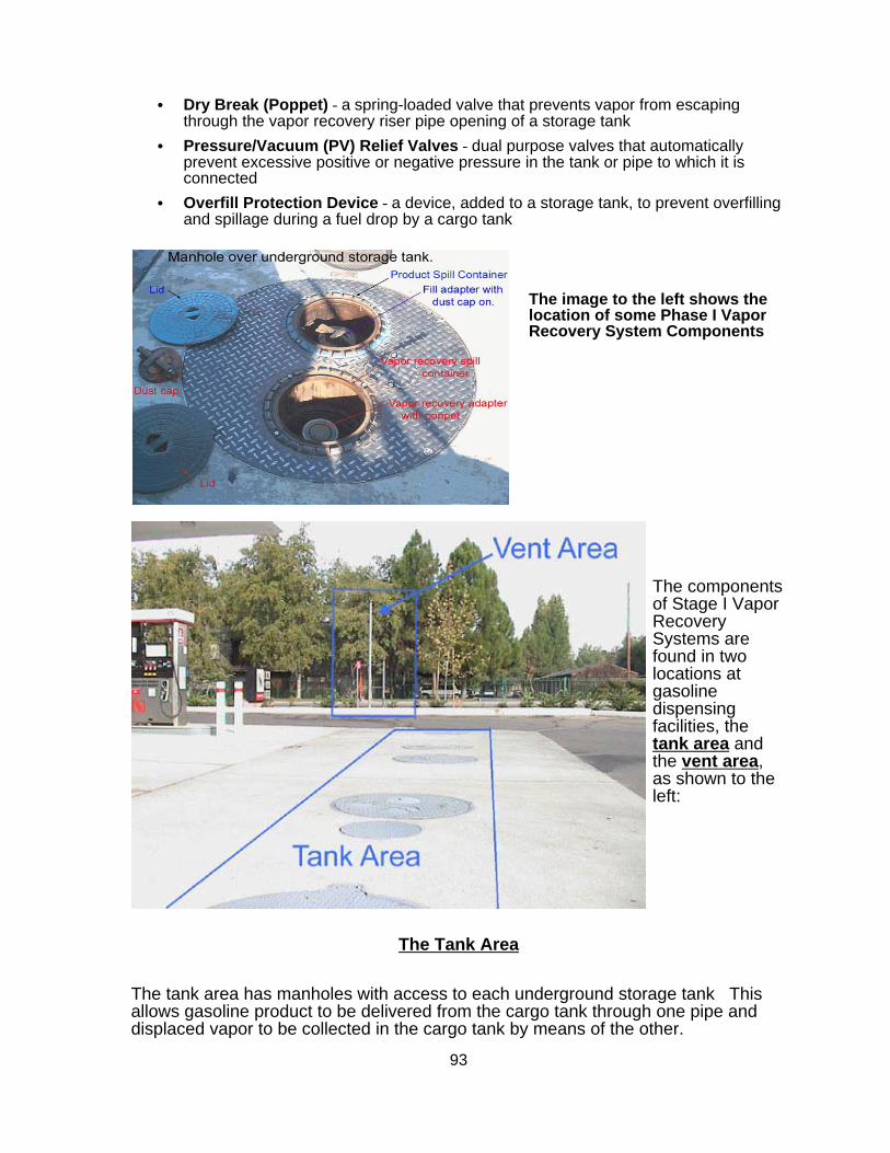
93
C Dry Break (Poppet) - a spring-loaded valve that prevents vapor from escapingthrough the vapor recovery riser pipe opening of a storage tank
C Pressure/Vacuum (PV) Relief Valves - dual purpose valves that automaticallyprevent excessive positive or negative pressure in the tank or pipe to which it isconnected
C Overfill Protection Device - a device, added to a storage tank, to prevent overfillingand spillage during a fuel drop by a cargo tank
The image to the left shows thelocation of some Phase I VaporRecovery System Components
The componentsof Stage I VaporRecoverySystems arefound in twolocations atgasolinedispensingfacilities, thetank area andthe vent area,as shown to theleft:
The Tank Area
The tank area has manholes with access to each underground storage tank Thisallows gasoline product to be delivered from the cargo tank through one pipe anddisplaced vapor to be collected in the cargo tank by means of the other.

94
The illustration below shows a typical tank area of a gasoline dispensing facility, witha cargo tanker delivering gasoline product to, and recovering vapor, from twounderground storage tanks.
The illustration below shows both product delivery and vapor recovery sides of atank, with some of the components labeled. In the dual, two point system, as shownin the illustration, the manhole above the underground storage tank contains twotank risers. One riser is for delivering product from the cargo tank to theunderground tank. The other riser, which includes the vapor recovery adapter(drybreak), is for delivering displaced vapor from the underground tank back to thecargo tank.

95
Stage I Product Delivery
The schematic to the left shows theproduct delivery piping.
Product is delivered to the UST fromthe cargo tank via a submerged pipecalled a drop tube.
The drop tube is guided into the USTby the tank riser pipe.
The Vent Area
Storage tanks have vent pipes equipped with pressure/vacuum (P/V) relief valves. P/Vvalves are designed to open at specified positive and negative pressures, so that the tank isprotected from physical damage or permanent deformation caused by routine increases ininternal pressure or vacuum. They also provide a safeguard in the event any pipes becomeblocked or inoperable. Additionally, the P/V valve setting on the tank vent is such that it actsas a flow control device that preferentially allows displaced vapors to pass to the tankercompartment during a drop.
Tanks need to breathe because of volume fluctuations due to temperature changes,barometric pressure changes, and variations in the vapor/liquid ratio during refueling. Whenthe internal pressure exceeds the valve design setting, the valve opens to vent the excesspressure to the atmosphere. When the vacuum exceeds the design setting, the valve opensto allow air to flow into the tank and relieve the excess vacuum condition.
The vent area contains one to three product vent lines, usually one vent for eachunderground storage tank. Each vent line must be capped with a pressure/vacuumrelief (P/V) valve, as shown in the illustration below on the right, or manifolded withthe other lines, as shown in the illustration on the left.
Thanks to California Air Resources Board, Stationary Source Division, Compliance Assistance Program VaporRecovery Interactive CD, August 2002; CARB Interactive CD w/ Stage I & II

96
5.2.1: Overview - Stage II
Section 5.2: Stage II Vapor Recovery
Phase II vapor recovery refers to the control of gasoline vapors during vehicle refueling.
Gasoline consists of a variety of hydrocarbon compounds and additives blended together toobtain the desired performance characteristics for gasoline engines. However, gasoline vaporsemitted into the atmosphere are a concern because they contain volatile organic compounds(VOCs) and hazardous air pollutants (HAPs) such as benzene. VOCs and oxides of nitrogen(NOx) emissions in the atmosphere react in the presence of sunlight to form ground-level ozone,known as smog. Smog burns your eyes, damages your lungs, makes breathing difficult, anddestroys crops and rubber products.
Two air pollution concerns from gasoline dispensing facilities are theamounts of VOC and toxic compound emissions that are emitted intothe atmosphere. These emissions tend to be concentrated in urbanareas, where air quality standards are most likely to be exceeded. Both Stage I and II gasoline vapor recovery lowers toxic exposure tothe general public, and significantly helps to minimize the release ofozone precursors that form smog.
Vapor recovery is a control strategy developed to collect vaporsgenerated during the transfer of gasoline in the marketing anddistribution process. Vapors are created due to the high volatility ofgasoline at atmospheric conditions. There is a strong tendency forgasoline to evaporate. When liquid evaporates in a closed system,molecules in the vapor state have a tendency to strike and condenseon the surface of the liquid. At a point when the rates of evaporation and condensation areequal, a state of equilibrium is achieved. When a system is in equilibrium the concentration ofvapor is highest near the surface of the liquid and decreases with the height above the surface.The pressure exerted by vapor in equilibrium with its liquid is referred to as vapor pressure.
Stage II vapor recovery captures saturated gasoline vapor that would otherwise escape into theenvironment when motorists refuel their vehicles (shown in Figure 1). This requires the use ofspecial dispensing nozzles fitted with vapor return lines that direct saturated vapor from the fillpipes of refueling vehicles to the stationary storage tank. By design, vapor displaced duringrefueling replaces the volume space created by the dispensed fuel from the undergroundstorage tank.

Chapter 5 Section 5.297
5.2.2: Federal Regulations
Figure 1 - Stage II Gasoline Vapor Recovery
Federal regulations set the minimum control requirements that must be incorporated into stateregulations. The Clean Air Act Amendments (CAAA) of 1990 require the installation of gasolinevapor recovery systems at dispensing facilities with throughputs greater than 10,000 gallons permonth in many ozone non-attainment areas across the United States.
For ozone, five non-attainment classes (marginal, moderate, serious, severe, and extreme) areused to match the air pollution control requirements with the severity of a region's air qualityproblem. Marginal designations are subject to the least stringent requirements while eachsubsequent classification is subject to more stringent requirements. Recovery of gasoline vaporfrom refueling vehicles is mandated for all moderate areas, as well as listed as serious, severeor extreme. As shown in Figure 2 on the following page, Southern New England is classified asa Serious Ozone Non-Attainment Area.

Chapter 5 Section 5.298
5.2.3: Rhode Island Regulations
5.2.4.: Requirements
Figure 2 – Federal Ozone Non-Attainment Regions
Stage II Vapor Recovery is addressed in DEM “Air Pollution Control Regulation No. 11,Petroleum Liquids Marketing And Storage”. The entire regulation can be found online onDEM’s website at: http://www.state.ri.us/dem/pubs/regs/REGS/AIR/AIR11-01.PDF. For Stage II Vapor Recovery,the owner or operator needs to be concerned with Rule 11.10 of this regulation, entitled,“Gasoline Dispensing Facilities – Stage II Vapor Controls. This workbook will discuss therequirements to be met in the regulation.
The Stage II Vapor Recovery requirements apply to:
C All gasoline dispensing facilities that were constructed or substantially modified afterNovember 15, 1992.
C All other gasoline dispensing facilities which have or have had a monthly throughputof greater than 10,000 gallons in any one month after November 1991.

Chapter 5 Section 5.299
5.2.4.1: Exemptions
5.2.4.2: Installation of Stage II Vapor Recovery Systems
5.2.4.3: General Maintenance and Inspection Requirements
Facilities that are exempted from this regulation must still comply with record keeping andreporting requirements that are outlined in Section 5.3.
1. To be exempted from the regulation because throughput has not exceeded 10,000gallons per month, the owner/operator of a gasoline dispensing facility is obligated todemonstrate in writing and with clear and convincing evidence that this has been thecase.
2. Facilities that were constructed or substantially modified after November 15, 1992 mayrequest from DEM in writing, an exemption from the Stage II regulatory requirements. Arequest for exemption must demonstrate:
(a) That monthly output has not exceeded 10,000 gallons in any month since November 1991, and will not exceed 10,000 gallons in any future month.
(b) That installation of a Stage II system at the facility is not technically and/oreconomically feasible.
(c) It must include the following information, at a minimum:
C nature of the facility
C number of dispensers, hoses, and nozzles
C number and volume of all gasoline storage tanks at the facility
C gasoline output for the facility for every month for the two years precedingthe request; for new facilities, expected maximum monthly gasolineoutput.
3. Stage II Vapor Recovery requirements, including record keeping and reporting, do notapply to gasoline dispensing facilities that dispense gasoline solely to marine vessels.
Persons who own, lease, operate or control a gasoline dispensing facility must comply with Rule11.10.2.1(a)-(e) of the regulation, relating to installation and training, prior to initial systemoperation. Please see that Rule for requirements that must be met.
Operating instructions for dispensing gasoline using the vapor recovery system mustbe posted conspicuously on the front of each dispensing pump. They must include:
C - a warning not to attempt to continue refueling after initial automatic shutoff
C the telephone number of the Department of Environmental Management
C a request that inoperable control devices be reported
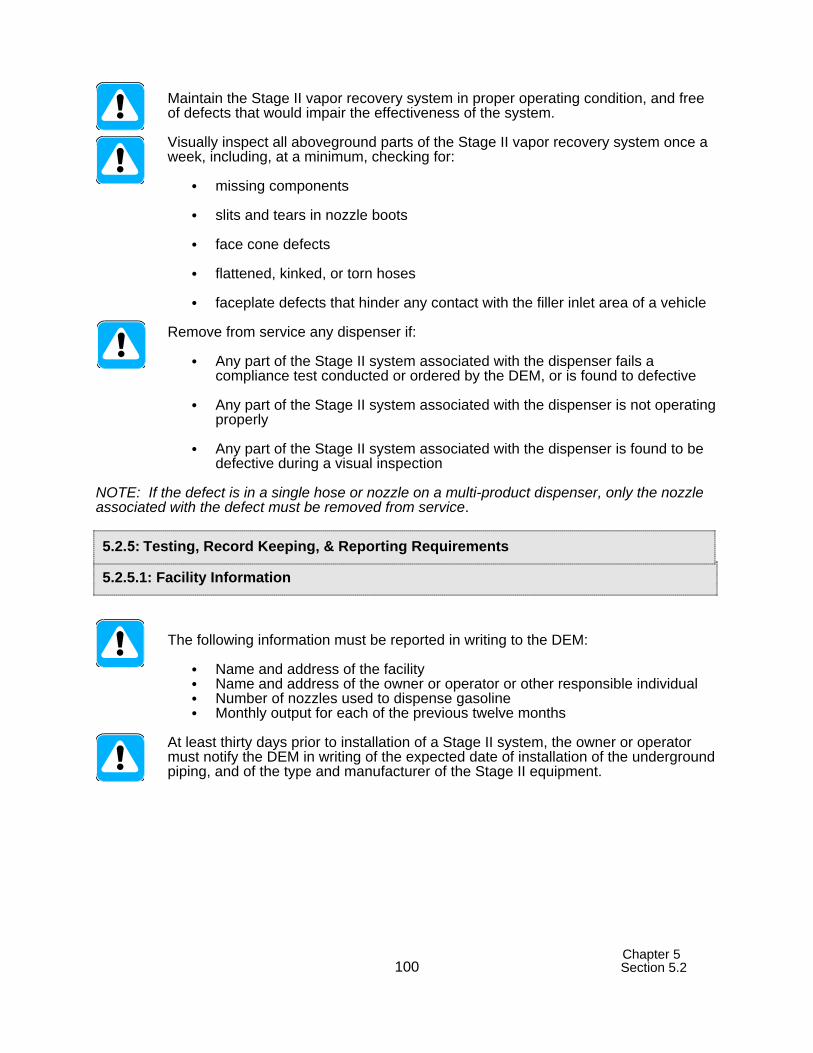
Chapter 5 Section 5.2100
5.2.5.1: Facility Information
5.2.5: Testing, Record Keeping, & Reporting Requirements
Maintain the Stage II vapor recovery system in proper operating condition, and freeof defects that would impair the effectiveness of the system.
Visually inspect all aboveground parts of the Stage II vapor recovery system once aweek, including, at a minimum, checking for:
C missing components
C slits and tears in nozzle boots
C face cone defects
C flattened, kinked, or torn hoses
C faceplate defects that hinder any contact with the filler inlet area of a vehicle
Remove from service any dispenser if:
C Any part of the Stage II system associated with the dispenser fails acompliance test conducted or ordered by the DEM, or is found to defective
C Any part of the Stage II system associated with the dispenser is not operatingproperly
C Any part of the Stage II system associated with the dispenser is found to bedefective during a visual inspection
NOTE: If the defect is in a single hose or nozzle on a multi-product dispenser, only the nozzleassociated with the defect must be removed from service.
The following information must be reported in writing to the DEM:
C Name and address of the facilityC Name and address of the owner or operator or other responsible individualC Number of nozzles used to dispense gasolineC Monthly output for each of the previous twelve months
At least thirty days prior to installation of a Stage II system, the owner or operatormust notify the DEM in writing of the expected date of installation of the undergroundpiping, and of the type and manufacturer of the Stage II equipment.

Chapter 5 Section 5.2101
5.2.5.2: Testing Requirements
5.2.5.3: Record Keeping
Prior to operation of the new system, the following tests must be conducted:
C A leak testC A liquid blockage test on each nozzleC A vapor space tie testC A ten gallon per minute test C For vacuum assist Stage II systems, an Air to Liquid Ratio test performed each nozzleC Any additional tests specified in the California Air Resources Board (CARB)
certification applicable to the Stage II system
Function of Stage II systems must be retested periodically as noted below:
C A leak test, a vapor space tie test, and a ten gallon per minute test must beperformed annually
C A liquid blockage test on each nozzle must be performed every three years
C For vacuum assist Stage II systems, an Air to Liquid Ratio test performed oneach nozzle must be performed annually
C Any additional tests specified in the CARB certification applicable to theStage II system according to the frequency in the certification
At least seven (7) days before testing, the owner or operator must notify DEM that testing will beconducted, and must certify within fifteen (15) days of the test that testing has been completed.
The following records must be kept for a period of five (5) years, and made availableto the DEM for inspection:
C Dates and result of weekly visual inspections, as required
C Date that any dispenser is removed from operation, and date returned to service
C Identification of parts repaired or replaced, and dates of replacement
C Identification of tests performed, and the dates and results
C Proof of attendance and completion of training for each employee who hasreceived Stage II training, maintained for as long as employees continue tobe employed at the facility.
NOTE: There must be a person with Stage II training present at the facility at all times when it isin operation.

Chapter 5 Section 5.2102
5.2.5.4: Weekly Visual Inspection Information
For exempted facilities (except for those facility dispensing gasoline to marine vesselsonly) the facility will maintain documented monthly output of gasoline, and make thoserecords available for inspection by DEM. The documentation will include:
C Dates and quantities of gasoline delivered
C Monthly records of gasoline dispensed
The vapor recovery system information below is provided to assist owners and operators withproperly identifying components of their systems, and completing the required weekly visualchecks.
The following items are components in Phase II vapor recovery systems:
C Fuel Dispenser C Vacuum Source (vacuum assisted systems only) C Hanging Hardware C Flow limiter (optional) C Whip hose C Breakaway C Coaxial Hose C Swivel C Nozzle
Stage II vapor recovery systems use either a vapor balance system or a vacuum assistedsystem.
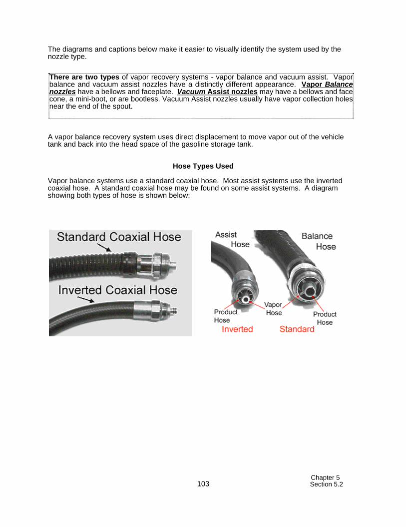
Chapter 5 Section 5.2103
There are two types of vapor recovery systems - vapor balance and vacuum assist. Vaporbalance and vacuum assist nozzles have a distinctly different appearance. Vapor Balancenozzles have a bellows and faceplate. Vacuum Assist nozzles may have a bellows and facecone, a mini-boot, or are bootless. Vacuum Assist nozzles usually have vapor collection holesnear the end of the spout.
The diagrams and captions below make it easier to visually identify the system used by thenozzle type.
A vapor balance recovery system uses direct displacement to move vapor out of the vehicletank and back into the head space of the gasoline storage tank.
Hose Types Used
Vapor balance systems use a standard coaxial hose. Most assist systems use the invertedcoaxial hose. A standard coaxial hose may be found on some assist systems. A diagramshowing both types of hose is shown below:

Chapter 5 Section 5.2104
Vapor Balance nozzles are readily identifiable by the bellows and faceplate.
Nozzles on Vapor Balance Systems
The diagram to the left shows product and vaporflow with a standard coaxial hose used on vaporbalance systems.
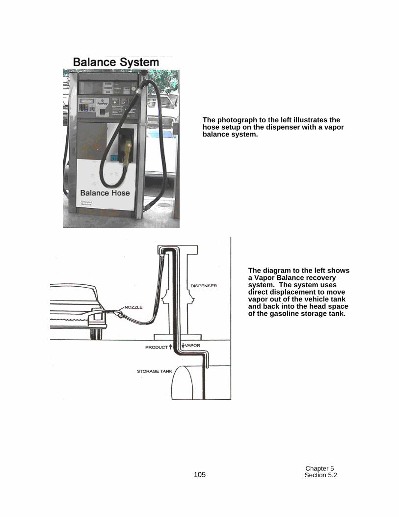
Chapter 5 Section 5.2105
The photograph to the left illustrates thehose setup on the dispenser with a vaporbalance system.
The diagram to the left showsa Vapor Balance recoverysystem. The system usesdirect displacement to movevapor out of the vehicle tankand back into the head spaceof the gasoline storage tank.

Chapter 5 Section 5.2106
Below is a diagram of a vapor balance nozzle with its components labeled, anddescribing items to be inspected in the weekly visual inspection:
% Dispenser - On each dispenser, fueling instructions must be clearly displayed, with theappropriate telephone number, which will allow consumers to register any complaintsregarding the refueling of vehicles.
% Bellows - Bellows must be securely attached to the nozzle and free of any deformitiesthat could hinder the recovery of vapor. Stretch the bellows to uncover any holes, rips ortears. The latching device, latch bar, rivet or ring must be present.
% Faceplate - Faceplates and face cones must be intact, and should be smooth anduniform with the faceplate, capable of providing a tight seal at the vehicle fill pipe.
% Check valve - The vapor check valve, normally installed at the base of the bellows, mustbe properly attached by a tightly fastened wire or clamp around the bellows, and must bechecked to make sure it is operating. The valve should open and close when the bellowsis compressed.
% Spout - The spout must be tight and the spout tip should be uniformly round.
% Hose - Check the whip hose for damage such as kinks, holes, rips and tears.
% Hose retractor – Check hose retractors, which keep hoses from dragging on the ground,and should fully retract the hose when the nozzle is properly replaced in the dispenser. Hose must not contact the ground.
% Liquid Accumulation – Check for presence of a liquid removal device. If the distancefrom the nozzle end of the hose to the lowest point of the hanging hose is more than ten(10) inches, the hose must have a liquid removal mechanism installed. When a liquidremoval device is not required, determine if there are any low points in which liquid could

Chapter 5 Section 5.2107
A nozzle for an assist vapor recovery system has vapor collection holes in the spout oraround the base of the spout. Vapor hole configuration varies depending on the nozzledesign. An assist nozzle may have a mini-boot. Because vapors are actually beingpulled from the auto fuel tank, it is important not to have a tight seal. A tight seal couldcreate a vacuum that could damage the fuel tank. Many new nozzles have mini-boots tocapture vapors that may escape around the spout.
sit. Observe whether or not liquid can be cleared by natural drainage into the vehicle orstorage tank when a nozzle is used.
C Check for liquid accumulation within the hanging hardware by using a 500 ml graduated cylinder, a funnel, and the following procedure:
1. Stretch the nozzle/hose assembly out to its limit. 2. Place the funnel inside the graduated cylinder and hold the nozzle
(spout pointed down) over the funnel. 3. Holding the nozzle in one hand, compress the nozzle bellows with
the other and drain any accumulated liquid into the funnel.
A Vacuum Assisted System is a gasoline vapor recovery system that uses a vacuum-inducingdevice to collect vapor from the receiving container and direct it back into the space of thecontainer from where the liquid product was withdrawn.
Nozzles on Vacuum Assisted Systems
The diagram to the left shows product and vapor flowwith an inverted coaxial hose used on most vacuumassist systems.

Chapter 5 Section 5.2108
Below are photographs of booted and bootless nozzles used with vacuum assisted vaporrecovery systems.
The photograph to the left illustrates the hosesetup on the dispenser with a vacuum assistsystem.

Chapter 5 Section 5.2109
The diagram below shows a Vacuum Assisted recovery system. The system pulls thevapors from the vehicle's fuel tank into the underground storage tank using a pump. Thevapor pump may be fluid driven, motor driven, or electronically driven. The pump, orpumps, may be located anywhere along the path from the dispenser to the tank.
Below is a description of items to be inspected in the weekly visual inspection of avacuum assisted system:
% Dispenser - On each dispenser, fueling instructions must be clearly displayed, with theappropriate telephone number, which will allow consumers to register any complaintsregarding the refueling of vehicles.
% Spout - The spout must be tight and the spout tip should be uniformly round. On coaxialspouts, check vapor holes for damage and or obstructions.
% Faceplate - Faceplates and face cones must be intact, and should be smooth anduniform with the faceplate, capable of providing a tight seal at the vehicle fill pipe.
% Check valve - The vapor check valve must be checked to make sure it is operating.
% Mini-boots (vapor guards) - Check condition of mini-boot.
% Product Hose - Check the product hose for damage such as kinks, holes, rips, tears,and crushed or kinked sections.
% Whip hose - Check the whip hose for damage such as kinked or crushed sections. Hose retractor - Hose retractors keep hoses from dragging on the ground and shouldfully retract the hose when the nozzle is properly replaced in the dispenser. Hoseretractors with weakened or broken springs should be repaired.
% Liquid Leaks - Inspect the entire length of the nozzle/hose assembly, from the dispenseroutlet casting to the nozzle end, for liquid leaks. Most leaks will occur at joints orconnections. Any nozzle/hose assembly with a leak needs to be tagged out of serviceand repaired.

Chapter 5 Section 5.2110
Healy nozzles are used exclusively with Healy assist systems. Healymanufactures all of the components of a Healy assist system. As shown below,different information is found on the left and right side of the nozzle.
Nozzles on Healy Systems
The Healy system is a vacuum assisted vapor recovery system with a dispenser basedelectrically driven vacuum pump, or a fluid driven, aspirated assist vapor recovery system.
The Healy/Franklin and the Healy Model 600 ORVR/800 Nozzle Systems utilize one vacuumpump per dispenser instead of one vacuum pump per fueling point. The vacuum pumps withthese systems run at a constant speed, creating a constant vacuum level within the dispenservapor piping, from the pump inlet to the nozzle. This vacuum is then regulated by the nozzle tomaintain the correct air-to-liquid ratio.
Left side Right side
Healey has manufactured a nozzle,shown to the left, that is compatiblewith vehicular refueling vaporrecovery (ORVR)

Chapter 5 Section 5.2111
Below is a description of items to be inspected in the weekly visual inspection of a Healyassist system:
% Dispenser - On each dispenser, fueling instructions must be clearly displayed, with theappropriate telephone number, which will allow consumers to register any complaintsregarding the refueling of vehicles.
% Spout - The spout must be tight and the spout tip should be uniformly round.
% Faceplate - Faceplates and face cones must be intact, and should be smooth anduniform with the faceplate, capable of providing a tight seal at the vehicle fill pipe.
% Check valve - The vapor check valve must be checked to make sure it is operating.
% Hose - Check the whip hose for damage such as kinks, holes, rips and tears.
The regulation requires that written weekly inspection records be kept for a period of five (5)years.
Thanks to California Air Resources Board, Stationary Source Division, Compliance Assistance Program Vapor Recovery Interactive CD, August 2002; CARB Interactive CD w/ Stage I & II

A-1
Appendix A: For More InformationThis section identifies UST program contacts and other resources that can help answer yourquestions and provide you with information about good UST management.
State Regulatory Agency InformationRI DEM Office of Waste Management235 Promenade StreetProvidence, RI 02908 (401) 222-2797
WEB SITE: www.state.ri.us/dem
Internet Resources
Government Links• U.S. Environmental Protection Agency’s Office of Underground Storage Tanks
Home Page: http://www.epa.gov/oust. To go directly to the complianceassistance section of the Home page go to: http://www.epa.gov/swerust1/cmplastc/index.htm. To go directly to EPA’s listingof publications, go to: http://www.epa.gov/swerust1/pubs/index.htm.
Professional And Trade Association Links• American Petroleum Institute (API): http://www.api.org/ • American Society of Testing and Materials (ASTM):
http://www.astm.org/index.html• Fiberglass Tank and Pipe Institute (FTPI): http://www.fiberglasstankandpipe.com• NACE International - The Corrosion Society: http://www.nace.org/• National Fire Protection Association (NFPA) : http://www.nfpa.org• Petroleum Equipment Institute (PEI): http://www.pei.org• Steel Tank Institute (STI): http://www.steeltank.com/• Underwriters Laboratories (UL): http://www.ul.com
Free Informative Publications Available
The publications listed on the next pages are free and available from the U.S. EnvironmentalProtection Agency (EPA). You can access these publications via EPA’s website or you can call,write to, or fax EPA. You can download, read, or order documents fromhttp://www.epa.gov/swerust1/pubs/index.htm. To order free copies or ask questions, call EPA'stoll-free RCRA/Superfund Hotline at 800-424-9346 or call EPA’s publication distributor’s toll-free number at 800-490-9198 or fax 513-489-8695. You can also write and ask for freepublications by addressing your request to EPA’s publication distributor: National ServiceCenter for Environmental Publications (NSCEP), Box 42419, Cincinnati, OH 45242. Fax-on-Demand allows you to call 202-651-2098 on your fax to access over 220 UST documents.

A-2
Document Description
General Information about USTs and your requirements
Catalog Of EPA Materials OnUSTs (January 2000)
An annotated list of UST materials, including orderinginformation. Most of the leaflets, booklets, videos, and softwareitems listed provide UST owners and operators with informationto help them comply with federal UST requirements.
Operating and MaintainingUnderground Storage TankSystems: Practical Help andChecklists (August 2000)
Contains brief summaries of the federal UST requirements foroperation and maintenance (O&M), as well as practical help thatgoes beyond the requirements. Checklists prompt the user tolook closely at what kinds of equipment are in use and how tokeep that equipment working properly over the lifetime of theUST system. The manual provides record keeping forms thatalso help the UST owner and operator keep equipmentoperating properly.
Musts For USTs: A SummaryOf Federal Regulations ForUnderground Storage TankSystems (July 1995)
Plain language summary of federal UST requirements forinstallation, release detection, spill, overfill, and corrosionprotection, corrective action, closure, reporting and recordkeeping.
Underground Storage Tanks:Requirements And Options(June 1997)
Trifold leaflet alerts UST owners and operators who are“nonmarketers” (who do not sell stored petroleum) of theirresponsibilities and choices for complying with Federal USTregulations.
Leak Detection Information
Straight Talk On Tanks: LeakDetection Methods ForPetroleum UndergroundStorage Tanks (September1997)
Explains federal regulatory requirements for leak detection andbriefly describes allowable leak detection methods.
Automatic Tank GaugingSystems for Release Detection:Reference Manual forUnderground Storage TankInspectors (August 2000)
Contains detailed information on automatic tank gauging (ATG)systems, including information on various types of ATGs, information on certified detectable leak rate/threshold, testperiod duration, product applicability, calibration requirements,restrictions on the use of the device, vendor contact information,printing and interpreting reports, sample reports, and so on.
Getting The Most Out Of YourAutomatic Tank GaugingSystem (March 1998)
Trifold leaflet provides UST owners and operators with a basicchecklist they can use to make sure their automatic tank gaugingsystems work effectively and provide compliance with federalleak detection requirements.

Document Description
A-3
Doing Inventory Control Right:For Underground StorageTanks (November 1993)
Booklet describes how owners and operators of USTs can useinventory control and periodic tightness testing to temporarilymeet federal leak detection requirements. Contains recordkeeping forms.
Manual Tank Gauging: ForSmall Underground StorageTanks (November 1993)
Booklet provides simple, step-by-step directions for conductingmanual tank gauging for tanks 2,000 gallons or smaller.Contains record keeping forms.
List Of Leak DetectionEvaluations For UST Systems,9th Edition (November 2001)
A summary of specifications, based on third-party certifications,for over 275 systems that detect leaks from USTs and theirpiping. Each summary provides information on such items ascertified detectable leak rate/threshold, test period duration,product applicability, calibration requirements, restrictions on theuse of the device, and so on.
Introduction To StatisticalInventory Reconciliation: ForUnderground Storage Tanks(September 1995)
Booklet describes how Statistical Inventory Reconciliation (SIR)can meet federal leak detection requirements (12 pages).
Closing Underground Storage Tanks Information
Closing Underground StorageTanks: Brief Facts (July 1996)
Trifold leaflet presents “brief facts” on properly closing USTs inorder to comply with federal closure requirements.
Financial Responsibility Information
Dollars and Sense: FinancialResponsibility Requirementsfor Underground StorageTanks (July 1995)
Booklet summarizes the “financial responsibility” required of USTowners and operators.
List of Known InsuranceProviders for UndergroundStorage Tanks (January 2000)
Booklet provides UST owners and operators with a list ofinsurance providers who may be able to help them comply withfinancial responsibility requirements by providing suitableinsurance mechanisms.
Financial Responsibility forUnderground Storage Tanks: AReference Manual (January2000)
This detailed, comprehensive manual provides UST inspectorswith the restrictions, limitations, and requirements of eachfinancial responsibility mechanism provided in the federal USTregulations.

B-1
Appendix B: Sample Placards for Overfill Devices
DELIVERY PERSON — AVOID OVERFILLS
# An overfill alarm is used for overfill protection at thisfacility.
# Do not tamper with this alarm in any attempt to defeatits purpose.
# When the tank is 90% full or is within 1 minute ofbeing overfilled, the overfill alarm sounds and/or alight comes on or flashes.
# If you hear the alarm sound or see the light on orflashing, STOP THE DELIVERY IMMEDIATELY!

B-2
DELIVERY PERSON — AVOID OVERFILLS# A ball float valve is used for overfill protection at this
facility.
# Do not tamper with this device in any attempt to defeatits purpose.
# When the tank is 90% full, or 30 minutes prior towhen the product would overfill the tank, the ballfloat will activate and the flow rate of the delivery willdecrease noticeably.
# When you notice a decrease in flow rate, STOP THE DELIVERY IMMEDIATELY!

B-3
DELIVERY PERSON — AVOID OVERFILLS# An automatic shutoff device is used for overfill
protection at this facility.
# Do not tamper with this device in any attempt to defeatits purpose.
# When the tank is 95% full or before the fittings ontop of the tank are exposed to fuel, the device willactivate and slow down, and then stop, the deliverybefore the tank is overfilled.
# When the automatic shutoff device activates, STOP THE DELIVERY IMMEDIATELY!

Appendix C C-1
Appendix C: Sample Emergency Numbers List
Important Contact InformationContact Name Phone #
State UST Agency: Rhode Island DEM(401) 222-2797 (or call the 24 hrEmergency Hotlineat (401) 222-3070)
Local UST Agency:
Fire Department:
Ambulance:
Police Department:
Repair Contractor:
Other Contacts:
U Release Response Checklist‘ Stop the release: Take immediate action to prevent the release of more product. Turn off the
power to the dispenser and “bag” the nozzle. Make sure you know where your emergency shutoffswitch is located. Empty the tank, if necessary, without further contaminating the site.
‘ Contain the spill or overfill: Contain, absorb, and clean up any surface releases. Identify any fire,explosion or vapor hazards and take action to neutralize these hazards.
‘ Call for help and to report suspected or confirmed releases: Contact your local fire emergencyresponse authority. Contact the DEM UST Section at (401) 222-2797 immediately. After hoursreleases may be reported to the DEM 24-hour Emergency Response Hotline at (401) 222-3070.

D-1
Appendix D: Cathodic Protection Testing Form(for use by a qualified cathodic protection tester)
TEST DATE:___/___/___ FACILITY NAME/ID:________________________________________________________
NOTE: Provide site sketch as directed on the back of this page.
Cathodic Protection (CP) Tester Information:Name: ________________________________ Phone Number:__________________________
Address:___________________________________________________________________________
Testing must be conducted by a qualified CP tester. Indicate your qualifications as a CP tester:
Identify which of the following testing situations applies:‘ Test required within 6 months of installation of CP system (installation date was ___/___/___)‘ Test required at least every 3 years after installation test noted above‘ Test required within 6 months of any repair activity – note repair activity and date below:
Indicate which industry standard you used to determine that the Cathodic Protection test criteria areadequate: ___________________________________
Cathodic Protection Test Method Used (check one)100 mV Cathodic Polarization Test
-850 mV Test (Circle 1 or 2 below)
1) Polarized Potential (“instant off”) 2) Potential with CP Applied , IR Drop Considered
Note: All readings taken must meet the -850 mV criteria to pass
Other Accepted Method (please describe):
Is the Cathodic Protection System working properly? Yes No (circle one)
My signature below affirms that I have sufficient education and experience to be a cathodic protectiontester; I am competent to perform the tests indicated above; and that the results on this form are acomplete and truthful record of all testing at this location on the date shown.
CP Tester Signature: _______________________________ Date:_____________
Site Sketch: Provide a rough sketch of the tanks and piping, the location of each CPtest, and each voltage value obtained (use space below or attach separate drawing).Voltage readings through concrete or asphalt do not provide accurate readings and are

D-2
not acceptable. Perform sufficient testing to evaluate the entire UST system.
If CP System fails a test, you must have a corrosion expert fix the system. If your CPsystem does not meet the requirements for cathodic protection, you must have a corrosionexpert investigate and fix the problem. A corrosion expert has additional training, skills, andcertification beyond the corrosion tester who filled out the bulk of this form. A corrosion expertmust be 1) accredited/certified by NACE International, the Corrosion Society, as a corrosionspecialist or cathodic protection specialist, or 2) a registered professional engineer withcertification or licensing in corrosion control. As long as you have the UST, be sure you keep arecord that clearly documents what the corrosion expert did to fix your CP system.
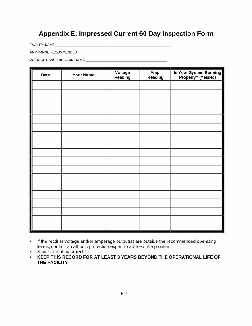
E-1
Appendix E: Impressed Current 60 Day Inspection FormFACILITY NAME:_______________________________________________________________
AMP RANGE RECOMMENDED:____________________________________________________
VOLTAGE RANGE RECOMMENDED:_________________________________________________
Date Your Name VoltageReading
Amp Reading
Is Your System RunningProperly? (Yes/No)
• If the rectifier voltage and/or amperage output(s) are outside the recommended operatinglevels, contact a cathodic protection expert to address the problem.
• Never turn off your rectifier.• KEEP THIS RECORD FOR AT LEAST 3 YEARS BEYOND THE OPERATIONAL LIFE OF
THE FACILITY
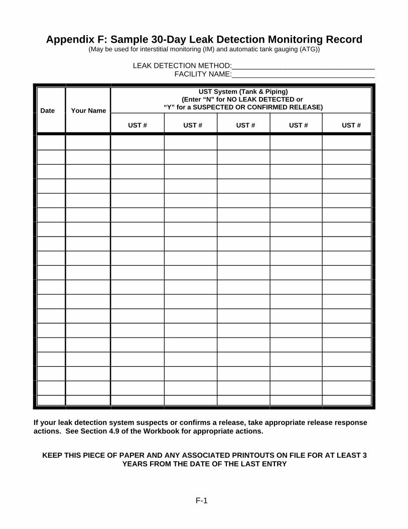
F-1
Appendix F: Sample 30-Day Leak Detection Monitoring Record(May be used for interstitial monitoring (IM) and automatic tank gauging (ATG))
LEAK DETECTION METHOD:___________________________________FACILITY NAME:___________________________________
Date Your Name
UST System (Tank & Piping)(Enter “N” for NO LEAK DETECTED or
“Y” for a SUSPECTED OR CONFIRMED RELEASE)
UST # UST # UST # UST # UST #
If your leak detection system suspects or confirms a release, take appropriate release responseactions. See Section 4.9 of the Workbook for appropriate actions.
KEEP THIS PIECE OF PAPER AND ANY ASSOCIATED PRINTOUTS ON FILE FOR AT LEAST 3YEARS FROM THE DATE OF THE LAST ENTRY

G-1
Appendix G: Sample Daily Inventory WorksheetFACILITY NAME: _________________________________________
YOUR NAME: ____________________________________________
DATE: __________________________________________________
TANK IDENTIFICATION
Type of Fuel
Tank Size in Gallons
END STICK INCHES
AMOUNT PUMPED 9 9 9 9 9
Totalizer Reading
Totalizer Reading
Totalizer Reading
Totalizer Reading
Totalizer Reading
Totalizer Reading
Totalizer Reading
Totalizer Reading
TODAY'S SUM OFTOTALIZERS
Previous Day's Sum of Totalizers
AMOUNT PUMPED TODAY
DELIVERY RECORD 9 9 9 9 9
Inches of Fuel Before Delivery
Gallons of Fuel BeforeDelivery
(from tank chart)
Inches of Fuel After Delivery
Gallons of Fuel After Delivery(from tank chart)
GALLONS DELIVERED(STICK)[Gallons "After" ! Gallons "Before"]
GROSS GALLONSDELIVERED (RECEIPT)

G-2
Sample Monthly Inventory RecordMONTH/YEAR :______/______ TANK IDENTIFICATION & TYPE OF FUEL:_____________________________
FACILITY NAME:_________________________________________________
DATE OF WATER CHECK: _________ LEVEL OF WATER (INCHES):______
DATE
START STICKINVENTORY(GALLONS)
GALLONSDELIVERED
GALLONS PUMPED
BOOK INVENTORY(GALLONS)
END STICK INVENTORY__________________________
(INCHES) (GALLONS)
DAILY OVER (+)OR SHORT (!)
["End" ! "Book"]INITIALS
1 (+) (-) (=)2 (+) (-) (=)3 (+) (-) (=)4 (+) (-) (=)5 (+) (-) (=)6 (+) (-) (=)
7 (+) (-) (=)8 (+) (-) (=)9 (+) (-) (=)7 (+) (-) (=)8 (+) (-) (=)9 (+) (-) (=)
10 (+) (-) (=)11 (+) (-) (=)12 (+) (-) (=)13 (+) (-) (=)14 (+) (-) (=)15 (+) (-) (=)16 (+) (-) (=)17 (+) (-) (=)18 (+) (-) (=)19 (+) (-) (=)20 (+) (-) (=)21 (+) (-) (=)22 (+) (-) (=)23 (+) (-) (=)24 (+) (-) (=)25 (+) (-) (=)26 (+) (-) (=)27 (+) (-) (=)28 (+) (-) (=)29 (+) (-) (=)30 (+) (-) (=)31 (+) (-) (=)
TOTAL GALLONS PUMPED > TOTAL GALLONS OVER OR SHORT > LEAK CHECK: Compare these numbersDrop the last two digitsfrom the TOTAL GALLONSPUMPED number and enter here: _____________ + 130 = ____________ gallons
Is the "TOTAL GALLONS OVER OR SHORT" LARGER than "LEAK CHECK" result? YES NO (circle one)If your answer is "YES" for 2 MONTHS IN A ROW, notify the DEM immediately.
KEEP THIS PIECE OF PAPER ON FILE FOR AT LEAST 3 YEARS

H-1
Appendix H: Manual Tank Gauging Record For Waste Oil Tanks Less Than 2000 Gallons
MONTH _______________ YEAR _________TANK IDENTIFICATION: _____________________________
PERSON COMPLETING FORM:______________________________FACILITY NAME:_______________________________________
Circle your tank size, test duration, and weekly/monthly standards in the table below: FACILITY ID #_______________________
Tank Size MinimumDurationOf Test
Weekly Standard(1 test)
Monthly Standard(4-test average)
Compare your weekly readings and the monthly average of the 4 weeklyreadings with the standards shown in the table on the left.
If the calculated change exceeds the weekly standard, the UST may beleaking. Also, the monthly average of the 4 weekly test results must becompared to the monthly standard in the same way.
If either the weekly or monthly standards have been exceeded, the USTmay be leaking. As soon as possible, call the DEM to report thesuspected leak and get further instructions.
up to 550 gallons 36 hours 10 gallons 5 gallons
551-1,000 gallons (also requiresperiodic tank tightness testing)
36 hours 13 gallons 7 gallons
1,001-2,000 gallons (also requiresperiodic tank tightness testing)
36 hours 26 gallons 13 gallons
Start Test (month, day,
and time)
FirstInitialStick
Reading
SecondInitialStick
Reading
AverageInitial
Reading
InitialGallons(convertinches togallons)
[a]
End Test (month, day, and
time)
FirstEndStick
Reading
SecondEndStick
Reading
AverageEnd
Reading
EndGallons(convertinches togallons)
[b]
ChangeIn TankVolume
In Gallons+ or (—)[a—b]
Tank Passes Test
(circleYES or NO)
Date:Time: AM/PM
Date: Time: AM/PM
Y N
Date:Time: AM/PM
Date:Time: AM/PM
Y N
Date:Time: AM/PM
Date:Time: AM/PM
Y N
Date:Time: AM/PM
Date:Time: AM/PM
Y N
KEEP THIS PIECE OF PAPER ON FILE FOR AT LEAST 3 YEARS
To see how close you are to the monthlystandard, divide the sum of the 4 weekly
readings by 4 and enter result here >
Y N
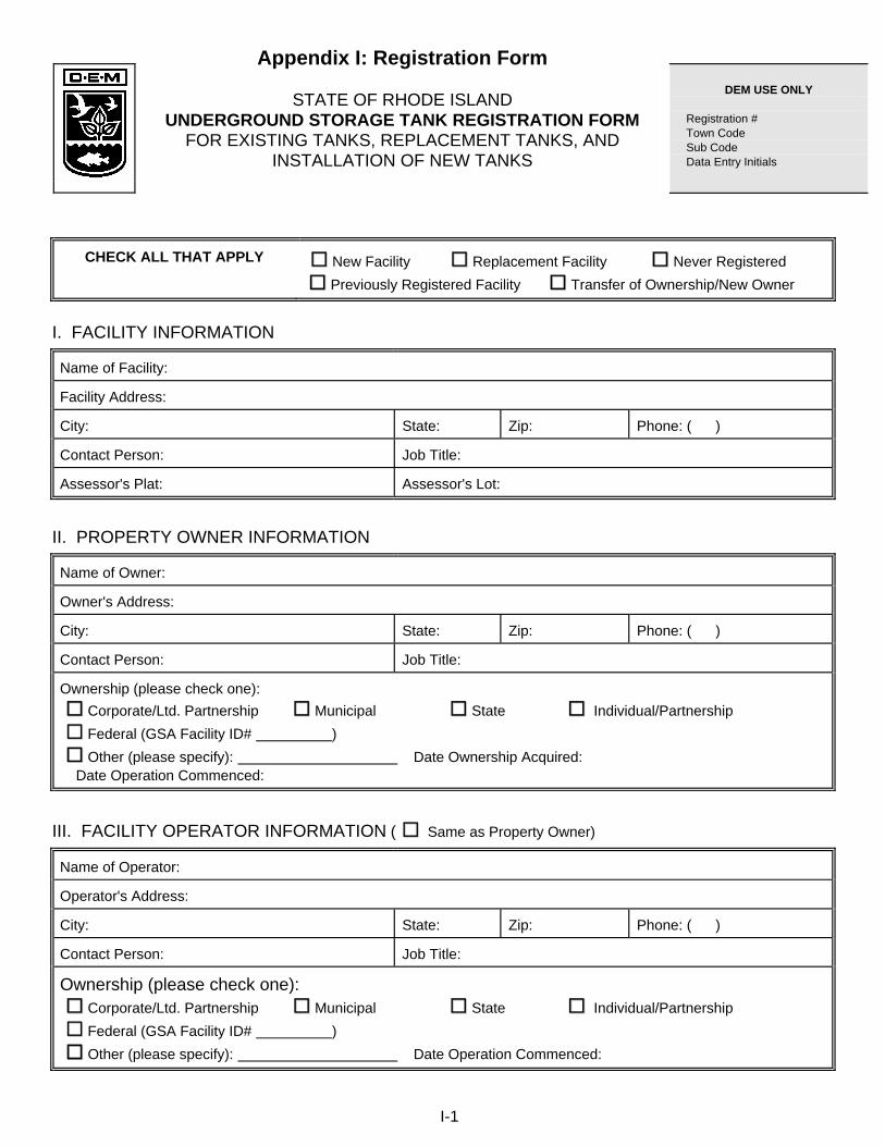
I-1
Appendix I: Registration Form
STATE OF RHODE ISLAND UNDERGROUND STORAGE TANK REGISTRATION FORM
FOR EXISTING TANKS, REPLACEMENT TANKS, AND INSTALLATION OF NEW TANKS
CHECK ALL THAT APPLY New Facility Replacement Facility Never Registered Previously Registered Facility Transfer of Ownership/New Owner
I. FACILITY INFORMATION
Name of Facility:
Facility Address:
City: State: Zip: Phone: ( )
Contact Person: Job Title:
Assessor's Plat: Assessor's Lot:
II. PROPERTY OWNER INFORMATION
Name of Owner:
Owner's Address:
City: State: Zip: Phone: ( )
Contact Person: Job Title:
Ownership (please check one): Corporate/Ltd. Partnership Municipal State Individual/Partnership Federal (GSA Facility ID# ) Other (please specify): Date Ownership Acquired: Date Operation Commenced:
III. FACILITY OPERATOR INFORMATION ( Same as Property Owner)
Name of Operator:
Operator's Address:
City: State: Zip: Phone: ( )
Contact Person: Job Title:
Ownership (please check one): Corporate/Ltd. Partnership Municipal State Individual/Partnership Federal (GSA Facility ID# ) Other (please specify): Date Operation Commenced:
DEM USE ONLY Registration # Town Code Sub Code Data Entry Initials

I-2
IV. TANK OWNER INFORMATION ( Same as Property Owner Same as Facility Operator)
Name of Tank Owner:
Mailing Address:
City: State: Zip: Phone: ( )
Contact Person: Job Title:
Ownership (please check one): Corporate/Ltd. Partnership Municipal State Individual/Partnership Federal (GSA Facility ID# ) Other (please specify): Date Ownership Acquired:
V. FACILITY CLASSIFICATION
(A) Farm (ES) Education/State (ET) Education/Town (EP) Education/Private (P) Private Residence (M) Multiple Residence (C) Commercial (I) Industrial (G) Gasoline Station (S) State Government (F) Federal Government (T) City/Town Government (FD) Nonprofit Fire District (O) Other (please specify):
VI. REGULATORY INFORMATION
Does the Facility have a drinking water well? YES NO If Yes, how far from the nearest tank? ft.
Is the facility within 400 feet of any public water supply wells or reservoirs? YES NO
Is the facility within 200 feet of any facility served by a private well? YES NO
Is the facility in or adjacent to State-regulated freshwater wetlands (including, but not limited to, swamps, ponds, marshes, watercourses, or 100-year floodplain)? Unknown YES NO If YES, Application or Complaint Number (if available):
Have any leaks or spills ever occurred at this facility? Unknown YES NO If Yes, an incident report must be attached to this application.
Are rcovery wells installed around this facility? YES NO
Are groundwater monitorin wells installed around this facility? YES NO
Does the facility have financial responsibility? YES NO If Yes, Insurer: Policy Number:

I-3
VII. TANK & PIPING INFORMATION (If more than 5 tanks – copy pages 3 & 4 and complete for additional tanks)
TANK Tank No. 1 Tank No. 2 Tank No. 3 Tank No. 4 Tank No. 5
Date of Installation (month/day/year) (If unknown, please enter 99)
/ / / / / / / / / /
Tank Capacity in Gallons
Tank Status: E = In Use C = Permanently Closed T = Temporarily Closed A = Abandoned
Material of Construction: (01) steel (04) fiberglass reinforced plastic (27) steel-fiberglass-reinforced plastic (20) double-wall steel (23) double-wall fiberglass (reinforced plastic) (31) alcohol resistant (06) concrete (99) unknown other (specify)
External Corrosion Protection: (11) cathodic protection (15) asphalt/tar coated (97) fiberglass/plastic/epoxy coated (98) none (99) unknown other (specify)
Internal Protection: (17) internal lining (18) wear plate (19) submerged fill tube (98) none (99) unknown other (specify)
Piping: (R) pressurized (I) suction other (specify)
Piping Construction: (28) equipped with secondary containment (01) bare steel (04) fiberglass-reinforced plastic (20) double wall steel (23) double wall fiberglass-reinforced plastic (29) flexible single wall (30) flexible double wall (31) alcohol resistant (32) cathodic protection (09) coated/wrapped (99) unknown other (specify)

I-4
TANK Tank No. 1 Tank No. 2 Tank No. 3 Tank No. 4 Tank No. 5
Monitoring & Leak Detection System: (Check all that apply) line leak detection (piping) sump monitoring (piping) continuous in-tank gauging system continuous interstitial space tank monitoring groundwater monitoring wells precision test (tank & piping) (provide copies) other (specify)
Overfill Prevention Equipment: high-level alarm flow restriction float vent valve automatic shut-off valve other (specify)
Spill Prevention Equipment: spill containment basin shear valve/impact valve (pressurized piping) check valve (suction piping) other (specify):
Substance Stored or to be Stored (mark only one box): (02) heating oil (No. 2) - consumed on site (2C) heating oil (No. 2) - consumed off site (04) heating oil (No. 4) - consumed on site (4C) heating oil (No. 4) - consumed off site (05) heating oil (No. 5) - consumed on site (5C) heating oil (No. 5) - consumed off site (06) heating oil (No. 6) - consumed on site (6C) heating oil (No. 6) - consumed off site (1D) light diesel fuel (No. 1-D) (2D)medium diesel fuel (No. 2-D) (01) number 1 kerosene (UG) regular/midgrade unleaded gasoline (SU) super unleaded gasoline (GH) gasohol (alcohol-gasoline blend) (DS) diesel (AG) aviation gasoline (JA) jet A (WO) waste oil (MO) motor oil (MX) mixture (specify) hazardous material (specify) CERCLA number: CAS number: (98) empty/no contents (99) unknown other (specify)

I-5
VIII. FACILITY SITE PLAN
EXISTING FACILITY If a detailed plan is not available, this space is provided for a site plan drawing of all equipment locations for facilities already in existence (see requirements in Rule 6, Facility Registration and Notification, of the RI DEM Rules and Regulations For Underground Storage Facilities Used For Petroleum Products and Hazardous Materials). NEW FACILITY If a new facility, a set of detailed engineering plans certified by a Registered Professional Engineer and project specifications including operation and maintenance requirements is required with this application (see Rule 6, Facility Registration and Notification, of regulations). All new facilities cannot use this space, separate installation plans must be submitted with this application. IX. CERTIFICATION
I certify under penalty of law that this document and all attachments were prepared under my direction or supervision in accordance with a system designed to assure that qualified personnel properly gather and evaluate the information submitted. Based on my inquiry of the person or persons who manage the system, or those persons directly responsible for gathering the information, the information submitted is, to be the best of my knowledge and belief, true, accurate, and complete. I am aware that there are significant penalties for submitting false information, including the possibility of fine and imprisonment for knowing violations. Authorized Signature Date Print Name and Title Please specify: Owner Operator Property Owner
rev. 10/02

I-6
UNDERGROUND STORAGE TANK (UST) REGISTRATION FORM If you are a tank owner, operator or own property (owner/operator) where a tank is located, you are considered responsible for the UST located at the facility. Please fill out the attached form indicating all USTs located at the facility that are currently in use or that will be brought into use, and which contains or will contain a "regulated substance". NEW AND REPLACEMENT TANKS AND/OR PRODUCT PIPING An owner/operator must apply for a certificate of registration before commencing construction. Upon receipt and review of a complete application and installation plans, written approval will be issued. No person shall commence construction of a new facility, replacement UST system, or a substantial modification to a UST system (including product piping replacement) until a written letter of approval has been issued authorizing the installation. REGISTRATION FEE Upon receipt of a completed application, the Department shall send an invoice for the payment of registration fees. Once the payment is received, a certificate of registration will be issued to the facility. All owners/operators who hold valid certificates of registration shall pay an annual registration fee of $75.00 for each underground storage tank so registered, except: - Owners/operators of one, two or three family dwellings with tanks used for storing fuel for residential
heating purposes (consumed solely on site); - Owners/operators of farm tanks storing fuel for heating purposes (consumed solely on site); - Federal, state and local governments; - Nonprofit fire districts. HOW TO COMPLETE REGISTRATION FORM Print in ink or type all items. Assign each tank a number and maintain that number consistently throughout this form and site plan. In Section VII of this registration form, mark each box with an "x" if it is applicable to the associated tank. PLEASE MAIL COMPLETED REGISTRATION FORMS TO: Department of Environmental Management Division of Waste Management Underground Storage Tank Section 235 Promenade Street Providence, Rhode Island 02908 If you have any questions, please call the Underground Storage Tank Section at (401) 222-2797 for assistance.

J-1
Appendix J: Transfer of Certification of Registration This document must be filled out by the new owner
This document must be notarized
FACILITY INFORMATION:
Facility Identification Number: _____________________________________________________________________________ Facility Name: _______________________________________________________________________________________________ Facility Address: ___________________________________________________________________________________ ___________________________________________________________________________________ Telephone Number: ________________________________________________________________________________ NEW OWNER(S) INFORMATION: TANK OWNER PROPERTY OWNER New Owner(s) Name: ________________________________________________________________________ New Owner(s) Address: _____________________________________________________________________ _____________________________________________________________________ Telephone Number: _________________________________________________________________________ Proposed Transfer Date: _____________________________________________________________________ CERTIFICATION: Please put an “X” in the box that applies: I have read the Original Application for a Certification of Registration and: Believe, to the best of my knowledge, that there has been no substantial modification in the operations of the facility since the certificate was issued. Believe, to the best of my knowledge, that there have been substantial modifications in the operation of the facility since the certification was issued; and I have included a description of all the changes that have occurred since the certificate was issued. Owner’s Signature: _________________________________________________________________________ TANK OWNER PROPERTY OWNER Notary Public Signature/Seal: ________________________________________________________________

Reminder of Typical Ongoing Testing Requirements for UST Systems(Keep the appropriate records of these tests!)
Spill Prevention and Overfill Protection
Type Activity Minimum Frequency
Spill Prevention Keep Spill Bucket Free of Product, Water, and Debris At all timesOverfill Alarm, AutomaticShutoff Device, Ball FloatValve, Vent Alarm
Inspect for Proper Operation Annually
Release Detection - Activities may vary on the type(s) of release detection you use
Release Detection Activity Minimum Frequency
Automatic Tank Gauging,and Interstitial Monitoring
Release Detection Monitoring Every 30 days
Inventory ControlInventory Measurements DailyReconcile Daily Inventory Control Measurements Once per monthCheck Tank for Water Once per monthTank Tightness Test Every 2 years
Manual Tank Gauging(for Waste Oil andEmergency GeneratorUSTs)
Inventory Measurements Weekly
Reconcile Weekly Manual Tank Gauge Tests Every 4 weeks
Tank Tightness Test (if required) Every Year
Line Leak Detector Test to Demonstrate Proper Function of Line LeakDetector
Every 12 months
Line Tightness Test Line Tightness Test - for pressurized piping Every 12 monthsLine Tightness Test - for suction piping Every 3 years
For all Release Detection Periodic Calibration and Maintenance of ReleaseDetection Equipment
Per Manufacturer’sInstructions
If you have Cathodic Protection - Activities vary depending on the type of cathodic protection
Cathodic Protection Activity Minimum Frequency
Impressed Current Rectifier Inspection - keep records for at least 3 years beyond theoperational life of the facility
Every 60 days
For both ImpressedCurrent and Galvanic(Sacrificial) Anodes
Cathodic Protection Test - performed by a qualified cathodic protection tester- keep records for at least 3 years beyond theoperational life of the facility
Within 6 months ofInstallationEvery 2 years for impressedcurrent systemEvery 3 years for sacrificialanode systemWithin 6 months of anyrepairs to your UST system
If you have Internal Lining
Internal Lining Activity Minimum Frequency
Internally Lined SteelTank
Internally Lined Tank Inspection - not required ifcombined with cathodic protection and tank passed anassessment before adding cathodic protection
- recommend keeping a record of the inspection
Within 10 years of installation
Every 5 years thereafter