environmental site design - harford county, md
TRANSCRIPT

Chapter
5.0
Envi
ronm
enta
l Site
Des
ign


Chapter 5. Environmental Site Design..........................................................................Introduction
5.1 Supp.1
Section 5.0 Introduction 5.0.1 Background The primary goal of Maryland’s stormwater management program is to maintain after development, as nearly as possible, the predevelopment runoff characteristics. Traditional stormwater management strategies treat runoff to mitigate adverse water quality and/or quantity impacts associated with new development. Designs applying these strategies often combine centralized structural practices for pollutant removal with channel erosion or flood control impoundments. These designs are less able to mimic predevelopment conditions because they focus on managing large volumes of polluted stormwater rather than treating runoff closer to the source. A comprehensive design strategy for maintaining predevelopment runoff characteristics and protecting natural resources is available. This strategy, known as Environmental Site Design or “ESD,” relies on integrating site design, natural hydrology, and smaller controls to capture and treat runoff. This chapter provides the foundation to refocus stormwater design from centralized management to more effective planning and implementation of ESD. 5.0.2 Requirements of the Stormwater Management Act of 2007 The “Stormwater Management Act of 2007” (Act), requires establishing a comprehensive process for stormwater management approval, implementing ESD to the maximum extent practicable (MEP), and ensuring that structural practices (see Chapter 3) are used only where absolutely necessary. The Act also establishes several performance standards for stormwater management plans. Designers must now ensure that these plans are designed to:
Prevent soil erosion from development projects. Prevent increases in nonpoint pollution. Minimize pollutants in stormwater runoff from both new development and redevelopment. Restore, enhance, and maintain chemical, physical, and biological integrity of receiving
waters to protect public health and enhance domestic, municipal, recreational, industrial and other uses of water as specified by MDE.
Maintain 100% of the average annual predevelopment groundwater recharge volume. Capture and treat stormwater runoff to remove pollutants. Implement a channel protection strategy to protect receiving streams. Prevent increases in the frequency and magnitude of out-of-bank flooding from large, less
frequent storms. Protect public safety through the proper design and operation of stormwater management
facilities. The Act presents a new opportunity to improve Maryland’s stormwater management program. The original Chapter 5 encouraged ESD through a series of optional credits for the design of nonstructural practices. Changes in response to the Act not only expand on the ESD practices first introduced in the Manual but also allow for planning techniques to improve implementation
NOTE: In this chapter, italics indicate mandatory criteria, whereas recommended criteria are shown in normal typeface.

Chapter 5. Environmental Site Design..........................................................................Introduction
and overall performance. The remaining sections of this chapter will further define ESD, discuss planning techniques used in its implementation, and provide design requirements for nonstructural and micro-scale practices used to treat runoff at the source. For reference purposes, the original Chapter 5 can be found in Appendix E.1. 5.0.3 Environmental Site Design Definition There are many stormwater design strategies that seek to replicate natural hydrology. Sometimes known as better site design, low impact development, green infrastructure, or sustainable site design, these strategies all espouse similar techniques. In each, a combination of planning techniques, alternative cover, and small-scale treatment practices is used to address impacts associated with development. For consistency, the Act adopts ESD as a more generic classification for use in Maryland. Title 4, Subtitle 201.1(B) of the Act defines ESD as “…using small-scale stormwater management practices, nonstructural techniques, and better site planning to mimic natural hydrologic runoff characteristics and minimize the impact of land development on water resources.” Under this definition, ESD includes:
Optimizing conservation of natural features (e.g., drainage patterns, soil, vegetation). Minimizing impervious surfaces (e.g., pavement, concrete channels, roofs). Slowing down runoff to maintain discharge timing and to increase infiltration and
evapotranspiration. Using other nonstructural practices or innovative technologies approved by MDE.
Impacts of Imperviousness The goal of traditional site design strategies is to maximize development potential by focusing on the layout of buildings, roads, parking, and other features. Conventional development practices tend to maximize site imperviousness and contribute to many of the impacts discussed in Chapter 1. These include diminished groundwater recharge, increased flows and runoff volumes, pollutant accumulation, and elevated water temperatures. Documentation such as the Impacts of Impervious Cover on Aquatic Systems (Center for Watershed Protection, 2003) and other studies of Eastern Piedmont and Coastal Plain streams in Maryland (Morgan and Cushman, 2005) and headwater streams in Montgomery County (Moore and Palmer, 2005) all indicate that stream biodiversity decreases as impervious cover increases. There is no simple formula, rule, or threshold for determining how much impervious cover may be sustained in a given watershed. Generally, stream quality and watershed health diminish when impervious cover exceeds 10% and become severely degraded beyond 25% (Center for Watershed Protection, 2003). Results from the Maryland Biological Stream Survey (MBSS) indicated that in surveyed streams, health was never good when watershed imperviousness exceeded 15%, (Boward, 1999). These studies establish a fundamental connection between impervious cover and watershed impairment.
Supp. 1 5.2

Chapter 5. Environmental Site Design..........................................................................Introduction
5.3 Supp.1
Integrating the fundamental principles of ESD during the planning process helps minimize the adverse impacts of imperviousness. The resulting designs reduce the need for costly infrastructure and maintenance while providing treatment closer to the source. To accomplish this, the designer must consider the basic concepts found in Section 5.1, Planning Techniques.

Chapter 5. Environmental Site Design...............................................Design Process and Planning
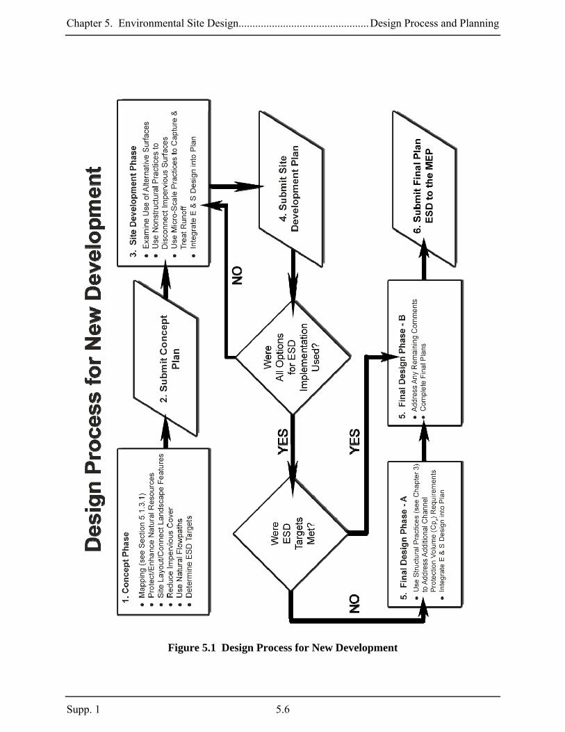
Section 5.1 Design Process and Planning Techniques 5.1.1 Introduction The design process described in this section will provide guidance for implementing ESD planning strategies and practices into a comprehensive site development plan. These techniques involve protecting natural resources, integrating erosion and sediment controls with stormwater management practices, minimizing site imperviousness, and using natural conveyance and ESD practices throughout the site. Applying these techniques early in the design process will ensure that all available resources have been considered in order to protect streams and waterways from the impact of land development activities. The design process will require the developer to adhere to the following procedures to achieve ESD to the MEP:
Following the Design Process for New Development as outlined in the step wise procedures in Figure 5.1.
Developing a map that identifies natural resource areas and drainage patterns and devising strategies for protection and enhancement.
Minimizing total site imperviousness by implementing clustered development and other better site design techniques.
Demonstrating that all reasonable opportunities for meeting stormwater requirements using ESD have been exhausted by using natural areas and landscape features to manage runoff from impervious surfaces and that structural BMPs have been used only where absolutely necessary.
Participate in the comprehensive review process for interim plans review and approval at the conceptual, site development, and final phases of project design.
Integrating strategies for erosion and sediment control and stormwater management into a comprehensive development plan.
5.1.2 Comprehensive Erosion & Sediment Control and Stormwater Management Review The Act requires that “a comprehensive process for approving grading and sediment control plans and stormwater management plans” shall be established. Therefore, county and municipal stormwater authorities shall establish a coordinated approval process among all appropriate local agencies. Erosion and sediment control review and approval authorities [e.g., local Soil Conservation Districts(SCD)] and input from any other local agency deemed appropriate (e.g., planning and zoning, public works) shall be included. The process will be tailored to meet local initiatives and should consider the scope and extent of environmental impacts for individual site developments. Review agencies involved will provide comments and approval during each of the following phases of plan development:
1. Concept 2. Site Development 3. Final
At each phase of this review process, the designer will receive feedback provided by the agencies allowing the developer to incorporate any concerns and recommendations throughout project
Supp. 1 5.4

Chapter 5. Environmental Site Design...............................................Design Process and Planning
planning and design. The concept plan will include site and resource mapping and protection and conservation strategies. The designer will also provide preliminary stormwater management ESD calculations. Review of the concept plan will ensure that all important resources have been mapped, protected, and all opportunities to enhance natural areas have been explored early in the design process. The site development plan will establish the footprint of the proposed project and demonstrate the relationship between proposed impervious surfaces and the existing natural conditions identified during concept plan design. This will better protect natural resources and buffers and allow for using ESD practices throughout the site. Included in this step are the preparation of detailed designs, computations, and grading plans for a second comprehensive review and approval. This ensures that all options for implementing ESD have been exhausted. After approval from the review agencies, the applicant will then proceed with final plan preparation including the design of any structural practices needed to address remaining channel protection requirements. Final plans will go to both the stormwater and erosion and sediment control review agencies for approval. The design process and planning techniques described in this section provide guidelines for protecting natural areas, minimizing imperviousness, using available landscaping for ESD practices, and integrating stormwater and erosion and sediment control strategies. Following this process will achieve the goal of implementing ESD to the MEP. Involving all review agencies from the beginning of site planning through the more detailed design will foster feedback and allow for a more efficient review and approval of final plans. 5.1.3 Design Process for New Development All new development projects shall be subject to the Design Process for New Development as outlined in the step wise procedures in Figure 5.1. As described above, the design process will require review and approval during three different phases of project planning that include the concept, site development, and final stages. Approving agencies shall use the process outlined in Figure 5.1 as an enforceable mechanism during review of the plan. Documentation that all steps were followed during project development and specific rationale to support the proposed design shall be required. 5.1.3.1 Concept Design Phase The concept design phase is the first step in project development as shown in Figure 5.1. This step will include the following:
Site and Resource Mapping Site Fingerprinting and Development Layout Locating ESD Practices
5.5 Supp.1
Chapter 5. Environmental Site Design...............................................Design Process and Planning
Supp. 1 5.6
Figure 5.1 Design Process for New Development

Chapter 5. Environmental Site Design...............................................Design Process and Planning
5.7 Supp.1
Site and Resource Mapping
d
nized by government regulatory
authority in Table 5.1 below.
Table 5. Resources and the C nding Regulatory Author
The resource mapping component will be used as a basis for all subsequent decisions during project design. During this step, the developer shall identify significant natural resources andemonstrate that these areas will be protected and preserved. Additionally, options will be evaluated to enhance important hydrologic functions. Approving authorities may require that other features be shown depending on site characteristics. This map shall be field verified by theproject designer. Specific areas that should be mapped are orga
1 Natural orrespo ities:
Federal State Local • Wetlands • Major waterway• Floodplains
nontida
ec
ams ins
• Critical Areas
ffers hy/slopes
s ative cover
• Existing drainage areas
s wetlands • Wetlands of Sp
• Tidal and l • Steep slopes
ial • Enhanced stream buState Concern
• Wetland buffers• Stream buffers • Perennial stre• Floodpla• Forests • Forest buffers
• Highly erodible soils
• Topograp• Springs• Seeps • Intermittent stream• Veget• Soils • Bedrock/geology
The mapping process will identify important natural resources as well as areas that are highly susceptible to erosion caused by construction activities. Identifying these important resourceand high risk locations and protecting them from disturbance is the first step in the planning process. When steep slopes and highly erodible soils are found measures need to be taken to limit disturbance and minimize impacts. This may be done by using information developed by the local SCDs. These offices maintain lists that identify highly erodible soil map units for each county in Maryland. Additionally, steep slopes are defined as those with gradients of 20 perceor more and moderately steep slopes fall within the range of 10 to 30 percent (USDA NRCSSoil Survey Manual, October, 1993). For the purpose of project planning, stee
s
nt ,
p slopes are onsidered to be any mapping unit with a slope class of 15 percent or greater.
sis of
emain undisturbed, protected during the construction process, and/or preserved as open space.
c While it may not be practicable to eliminate earth disturbing activities exclusively on the basoil erodibility or slope alone, constraints are warranted when both steep slopes and highlyerodible soils occupy the same area within the development footprint. Areas with highly erodible soils and slopes equal to or greater than 25 percent should be incorporated into adjacent buffers, r

Chapter 5. Environmental Site Design...............................................Design Process and Planning
Strategies to protect steep slopes and highly erodible soils include:
Identify and map all highly erodible soils and steep slopes; and Protect areas with highly erodible soils on slopes equal to or greater than 25 percent from
earth disturbing activities.
In addition to preserving sensitive areas during disturbances, the environmental benefits of other existing natural resources should be maximized by incorporating protection strategies into the overall goals of the project. Protecting these resources up front in the planning process will allow their many functions to be utilized for infiltration, flow attenuation, groundwater recharge, flood storage, runoff reduction, nutrient cycling, air and water pollution reduction, habitat diversity, and thermal impact reduction. When ESD practices are located later in the planning process, these protected areas may be further enhanced by using them to meet stormwater requirements. Natural resource protection and enhancement strategies include:
Protecting large tracts of contiguous open space, forested areas, and other important resources through conservation easements.
Identifying afforestation opportunities in open space areas and setting aside land for natural regeneration.
Identifying important resource areas that may be expanded such as stream buffers and floodplains.
Minimize disturbance to highly permeable soils. Site Fingerprinting and Development Layout
After conserving and protecting sensitive resources has been addressed, the next step in the planning process involves determining the approximate location of buildings, roadways, parking lots, and other impervious areas. These site improvements should be placed at a sufficient distance to protect the conservation areas. Protecting these resources will involve enhancing or expanding forested and stream buffers of adequate widths based on site characteristics. Minimum buffer widths may be expanded based on receiving stream characteristics, stream order, adjacent land slopes, 100-year floodplain, wetlands, mature forests, vegetative cover, depth of the groundwater table, and the presence of spring seeps and other sensitive areas. Several studies have suggested that minimum buffer widths could be based on site specific functions (Palone and Todd, 1998) including: bank stability and water temperature moderation (50 feet), nitrogen removal (100 feet), sediment removal (150 feet), or flood mitigation (200 feet). The approving agency may enhance existing buffer requirements depending upon resource protection goals identified at the local level. After the development footprint has been established, consideration should be given to natural drainage areas and how runoff will travel over and through the site. Sheetflow and existing drainage patterns should be maintained and discharges from the site should occur at the natural location wherever possible. New drainage patterns result in concentrated flow leaving the site at
Supp. 1 5.8

Chapter 5. Environmental Site Design...............................................Design Process and Planning
an inappropriate or unstable location, as well as creating erosion, sediment transport, and stream channel stability problems. The use of storm drains and engineered conveyance systems should be minimized by using vegetated swales and other natural systems so that forests, buffers and overland flow characteristics remain intact. Planning for on-site and off-site drainage patterns must be done early in the design process to establish a stable outfall for downstream discharges. Some of the strategies listed below can be used to establish nonstructural practices such as sheetflow to natural areas. These protection and enhancement tools, can then double as important strategies for meeting on-site stormwater requirements. Strategies for site layout and connecting landscape features include:
Plan the building footprint and layout to protect conservation areas. Evaluate opportunities to enhance/expand forested, wetland, and stream buffers. Grade the site so that runoff will flow from impervious areas directly to pervious areas or
other natural conveyance systems. Maintain natural flow paths between the site and upstream and downstream systems. Maintain sheetflow and natural overland flow processes wherever feasible. Provide stable conveyance of runoff off-site.
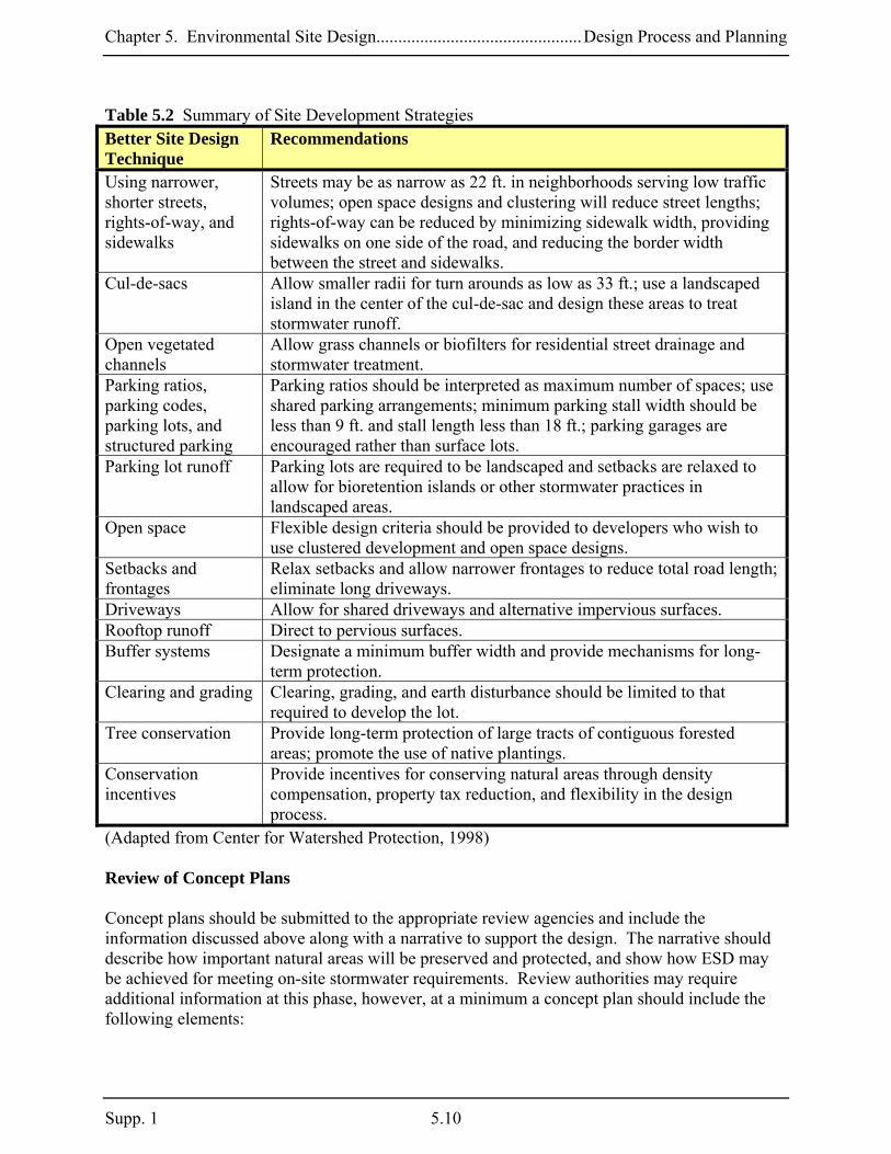
In addition to the site fingerprinting techniques described above, other strategies may be used to protect important natural resources. One type of practice that encompasses many of these design techniques in residential developments is clustering. This practice allows for concentrating development in one area, thereby reducing the distance between individual lots, the length of subdivision roadways, and overall impervious areas. It will also allow for protecting open space and buffer areas and reduce clearing and grading in natural areas. Commercial and industrial developments offer other opportunities to reduce impervious cover. Because parking lots are the dominant land cover for most commercial and industrial projects, designers can minimize the surface area dedicated to parking and use ESD practices in landscaped areas for stormwater treatment. Table 5.2 below provides a list of better site design techniques that may be used to reduce site imperviousness, protect environmentally sensitive areas, and provide more open space. More details and information may be found in, Better Site Design: A Handbook for Changing Development Rules in Your Community (Center for Watershed Protection, 1998). Locating ESD Practices
Reducing the impervious area in residential, commercial, and industrial development enhances the space available for landscaped features (e.g., parking lot islands, medians, plazas). Many of the micro-scale practices discussed in this chapter are tailored to fit in these smaller landscaped areas. When strategies for reducing imperviousness and protecting natural resources are combined with design options that distribute ESD practices throughout a site, the resulting plans will provide an effective means to address stormwater requirements at the source. After the site footprint has been established, preliminary calculations for determining stormwater requirements using ESD can be provided and potential management areas can be identified. The concept plan shall include a drawing or sketch identifying the preliminary location of ESD practices.
5.9 Supp.1
Chapter 5. Environmental Site Design...............................................Design Process and Planning
Table 5.2 Summary of Site Development Strategies Better Site Design Technique
Recommendations
Using narrower, shorter streets, rights-of-way, and sidewalks
Streets may be as narrow as 22 ft. in neighborhoods serving low traffic volumes; open space designs and clustering will reduce street lengths; rights-of-way can be reduced by minimizing sidewalk width, providing sidewalks on one side of the road, and reducing the border width between the street and sidewalks.
Cul-de-sacs Allow smaller radii for turn arounds as low as 33 ft.; use a landscaped island in the center of the cul-de-sac and design these areas to treat stormwater runoff.
Open vegetated channels
Allow grass channels or biofilters for residential street drainage and stormwater treatment.
Parking ratios, parking codes, parking lots, and structured parking
Parking ratios should be interpreted as maximum number of spaces; use shared parking arrangements; minimum parking stall width should be less than 9 ft. and stall length less than 18 ft.; parking garages are encouraged rather than surface lots.
Parking lot runoff Parking lots are required to be landscaped and setbacks are relaxed to allow for bioretention islands or other stormwater practices in landscaped areas.
Open space Flexible design criteria should be provided to developers who wish to use clustered development and open space designs.
Setbacks and frontages
Relax setbacks and allow narrower frontages to reduce total road length; eliminate long driveways.
Driveways Allow for shared driveways and alternative impervious surfaces. Rooftop runoff Direct to pervious surfaces. Buffer systems Designate a minimum buffer width and provide mechanisms for long-
term protection. Clearing and grading Clearing, grading, and earth disturbance should be limited to that
required to develop the lot. Tree conservation Provide long-term protection of large tracts of contiguous forested
areas; promote the use of native plantings. Conservation incentives
Provide incentives for conserving natural areas through density compensation, property tax reduction, and flexibility in the design process.
(Adapted from Center for Watershed Protection, 1998) Review of Concept Plans Concept plans should be submitted to the appropriate review agencies and include the information discussed above along with a narrative to support the design. The narrative should describe how important natural areas will be preserved and protected, and show how ESD may be achieved for meeting on-site stormwater requirements. Review authorities may require additional information at this phase, however, at a minimum a concept plan should include the following elements:
Supp. 1 5.10

Chapter 5. Environmental Site Design...............................................Design Process and Planning
• A map of all site resources shown in Table 5.1. • Field verification from the project engineer of the natural resource map. • Proposed limits of clearing and grading. • Location of proposed impervious areas (buildings, roadways, parking, and sidewalks). • Location of existing and proposed utilities. • Preliminary estimates of stormwater requirements. • Preliminary location of ESD practices. • Stable conveyance of stormwater at potential outfall locations. • A narrative that supports the concept and describes how the design will achieve.
o Natural resource protection and enhancement. o Maintenance of natural flow patterns. o Reduction of impervious areas through better site design, alternative surfaces, and
nonstructural practices. o Integration of erosion and sediment controls into the stormwater strategy. o Implementation of ESD planning techniques and practices to the MEP.
County and municipal stormwater management agencies are required to have a comprehensive review process in place so that input is provided for all aspects of development project planning, design, and construction. The review of concept plans begins this process. Stormwater and erosion and sediment control authorities will collaborate to provide coordinated feedback to the designer before a project proceeds to the more detailed site development phase. This feedback will accompany the concept plan approval and should be incorporated into future submissions. 5.1.3.2 Site Development Phase Preparation of site development plans will include more detailed designs for stormwater management and erosion and sediment control. During this phase the site footprint will be finalized with respect to the layout of buildings, roadways, parking, and other structures in order to develop more detailed design. The following plans will be required for site development review:
Stormwater Management Erosion and Sediment Control An Overlay Showing Stormwater and Erosion and Sediment Control Practices
Stormwater Management Plans
After concept plan approval, the developer should use comments and feedback as a basis for the next design phase. When the development layout is finalized, the proposed topography may be determined and final drainage areas established. Natural features and conservation areas can be utilized to serve stormwater quantity and quality management requirements. Individual ESD locations will be determined and all alternative surfaces, nonstructural, and micro-scale practices will be finalized. When locating and sizing ESD practices, the primary objective is to manage runoff as close to its source as possible by using vegetated buffers, natural flow paths, sheetflow to natural areas, and landscape features. ESD practices are then designed according to sizing requirements specified later in this chapter and discharge computations and storage volumes
5.11 Supp.1

Chapter 5. Environmental Site Design...............................................Design Process and Planning
provided. Calculations and details will be submitted to the review agencies to verify the design approach. Section 5.2 provides more information on sizing requirements and design specifications for all ESD practices. A narrative will also be required to justify that the design will achieve ESD to the MEP.
Erosion and Sediment Control Plans After concept plan approval, the final grading and proposed drainage areas during construction will also be established. This is critical to developing erosion and sediment control plans. Erosion and sediment control plans prepared at this phase will include measures for:
Preservation Phasing and construction sequencing during each stage of development Design of sediment controls Stabilization strategies
Preservation Comments received during concept plan review should be used as a basis for preparing erosion and sediment control plans. Strategies to preserve sensitive resources, ensure soil stability, and prevent erosion begin with protecting those areas during project construction. Erosion and sediment control plans should identify areas to be protected by marking the limit of disturbance, sensitive areas, buffers, and forested areas that are to be preserved or protected. In addition, infiltration and recharge areas that need to be protected from fine sediments and compaction should be identified. Plans should also note that all protected areas be marked in the field prior to any land disturbing activity. Phasing and Sequences of Construction During Each Stage of Development The site development plan will provide sequences of construction for each stage of development. These include initial clearing and grubbing, rough grading, site development, and final grading. Because initial and final flow patterns will not apply to all intermediate phases, these sequences should consider flow pattern changes, drainage areas, and discharge points at transitional phases of the construction process. Phased plans need to ensure that erosion and sediment controls adequately address the changing runoff patterns. Erosion and sediment control strategies for minimizing erosion during interim grading include:
Interim plans to address grade changes and flow patterns during clearing and grading, rough grading, site development, and final grading.
Slope length and steepness reductions. Divert clean water around or through a site and discharge it to a stable outlet.
Supp. 1 5.12

Chapter 5. Environmental Site Design...............................................Design Process and Planning
Design of Sediment Controls Water handling practices need to provide erosion protection during site grading operations. This may be done by diverting runoff away from highly erodible soils, steep slopes, and disturbed areas by using dikes, swales, or reverse benches. Similarly, runoff can be safely conveyed from the top of slopes to a stable outfall using pipe slope drains or channels. Check dams may be needed to reduce velocities and prevent erosion. Runoff from all discharge points shall provide a stable outlet. Stabilization Strategies
When vegetation is removed and soil disturbance occurs, the extent and duration of exposure should be minimized. All efforts should be made to delay grading operations until it is certain that final grades can be reached in as little time as possible. Where this cannot be accommodated, soils shall be stabilized within 14 days of disturbance. The extent and duration of disturbance should be limited (e.g., 72 hours) and enhanced stabilization techniques such as soil stabilization matting or turf reinforcement used on areas with highly erodible soils and slopes greater than 15 percent. Soil exposure should be shortened by the local permitting authority if warranted by site conditions. Perimeter controls, perimeter slopes, and extreme grade modifications (e.g., slopes greater than 3:1 or where cuts and fills exceed 15 feet) require stabilization within seven days. Mass clearing and grading should be avoided with larger projects (e.g., 25 acres) being phased so disturbed areas remain exposed for the shortest time possible. All other areas should have a good cover of temporary or permanent vegetation or mulch. Natural vegetation should be retained in an undisturbed state wherever possible. If it is not possible to retain natural vegetation, the topsoil should be salvaged, stockpiled on-site, protected from erosion, and replaced at final grade. Topsoil removal, grading, and filling reduce soil quality resulting in detrimental impacts on plant growth and increase runoff. Additionally, the removal of topsoil inhibits biological activity and reduces the supply of organic matter and plant nutrients. Similarly, unrestricted use of construction equipment can result in soil compaction. Applicable practices include, but are not limited to, temporary and permanent seeding, sodding, mulching, plastic covering, erosion control fabrics and matting, the early application of gravel base on areas to be paved, and dust control. Soil stabilization measures should be appropriate for the time of year, site conditions, and estimated duration of use. Soil stockpiles must be stabilized, protected with sediment trapping or filtering measures, and be located away from storm drain inlets, waterways, and drainage channels. Linear construction activities, including right-of-way and easement clearing, roadway development, pipelines, and trenching for utilities shall be phased so that soils are stabilized as quickly as possible.
5.13 Supp.1

Chapter 5. Environmental Site Design...............................................Design Process and Planning
Strategies to limit the extent and duration that soils are exposed may include:
Minimizing disturbed area. Phasing earth disturbing activities so that the smallest area is exposed for the shortest
possible time. Salvaging topsoil for later use. Stabilizing as work progresses.
Overlay Plan Many of the stormwater ESD practices deal with alternative surfaces or are nonstructural and promote hydraulic connection of impervious surfaces with natural landscape features. The practices for stormwater management and erosion and sediment control may share the same location while serving different functions. For example, swales used initially to convey sediment-laden runoff to a trap or basin during the sediment control phase could be used for water quality treatment and flow attenuation of stormwater runoff at final grade. Similarly, natural berms and vegetative buffers coupled with traditional sediment filtering controls may be integrated into the site design and meet both sediment control and stormwater management requirements. Once the ESD practices have been located and sized appropriately, consideration to how these areas will function under proposed conditions is needed. The location of any ESD practice that requires natural infiltration needs to be identified on the plans and in the field. These areas need to be protected during construction. An overlay plan should include the location of all ESD practices to allow for efficient sediment control design and the protection of locations that will be used to treat stormwater. An overlay plan should include:
The location of ESD practices on the plan and in the field. The location of areas that must remain undisturbed, protected, or used for erosion and
sediment control. Identifiable areas where construction equipment may compact soil and will need
rehabilitation after grading operations. Removal of sediment from the locations of ESD practices. Stabilization measures needed to enhance stormwater functions.
Review of Site Development Plans Site development plans should be submitted to the appropriate review agencies and should include a stormwater plan, erosion and sediment control plan, an overlay plan, and a narrative to support the design. Review authorities may require additional information at this phase, however, at a minimum a site development plan shall include the following:
• All of the information provided in the concept review. • Comments received by review agencies during the concept review.
Supp. 1 5.14

Chapter 5. Environmental Site Design...............................................Design Process and Planning
• Determination of final site layout and acreage of total impervious area on site. • Proposed topography. • Proposed drainage areas at all points of discharge from the site. • Proposed stormwater volume requirements for ESD targets and quantity control. • The location and size of ESD practices used to the MEP and all nonstructural, alternative
surfaces, and micro-scale practices used. • Proposed hydrology analysis for runoff rates, storage volumes, and discharge velocities. • Stormwater design details and specifications. • Discharge calculations demonstrating stable conveyance of runoff off site. • Preliminary erosion and sediment control plans showing limits of disturbance, sensitive
areas, buffers, and forests that are to be preserved, proposed phasing, construction sequencing, proposed practices, and stabilization techniques.
• An overlay plan showing the location of stormwater ESD practices and proposed erosion and sediment controls.
• A narrative to support the site development design and demonstrate that ESD will be achieved to the MEP.
Stormwater and erosion and sediment control authorities will collaborate to provide coordinated feedback to the designer before a project proceeds to the more detailed final design phase. This feedback will accompany the site development approval and should be incorporated into future submission. 5.1.3.3 Final Plan Design and Review After site development plan approval, the developer may prepare final designs by incorporating comments from the appropriate review agencies. After all reasonable ESD options have been exhausted, structural practices may be needed (see Chapter 3) to address additional Cpv requirements. Final plan approval shall be required for issuing local grading and building permits. Review authorities may require additional information at this phase, however, at a minimum final plans shall include the following information and meet the requirements established in COMAR 26.17.01.05 and 26.17.02 .09:
• All of the information provided in the site development review. • Comments received by review agencies during the site development review. • Development details and site data including site area, disturbed area, new impervious
area, and total impervious area. • Existing and proposed topography. • Proposed drainage areas. • Representative cross sections and details (existing and proposed structure elevations and
water surface elevations). • The location of existing and proposed structures. • Construction specifications. • Operation and maintenance plans. • As-built design certification block. • Inspection schedule.
5.15 Supp.1
Chapter 5. Environmental Site Design...............................................Design Process and Planning
Supp. 1 5.16
• Easements and rights-of-way. • Certification by the owner/developer that all construction will be done according to the
plan. • Performance bonds. • Final erosion and sediment control plans. • Stormwater management report including;
o A narrative to support the final design and demonstrate that ESD will be achieved to the MEP.
o Table showing the ESD and Unified Sizing Criteria. o Hydrology and hydraulic analysis of the stormwater management system for all
applicable sizing criteria. o Final sizing calculations for stormwater controls including drainage area, storage,
and discharge points. o Final analysis of stable conveyance to downstream discharge points. o Geotechnical investigations including soil maps, borings, and site-specific
recommendations. The design process described above is intended to be iterative, as comments from all review agencies are incorporated during each phase of project design. This will help local jurisdictions coordinate with other programs requiring environmental review and ensure that development plans fit priorities for resource protection, enhancement, and restoration. Many counties have performed restoration assessments on targeted watersheds. The planning process described in Figure 5.1 and above allows individual site development to be evaluated in the context of these larger resource protection efforts.

Chapter 5. Environmental Site Design...................................................................... Sizing Criteria
Section 5.2 Addressing the Unified Sizing Criteria To accomplish the goal of maintaining predevelopment runoff characteristics, there must be a reasonable standard that is easily recognized, reproducible, and applied without opportunity for misrepresentation. The simplest and most effective solution is to eliminate the need for evaluating predevelopment conditions on a site-by-site basis and apply the same standard to all sites. For rainfall amounts less than two to three inches, there is little difference in the amount of runoff from most sites in undeveloped conditions although runoff amounts are lowest for woods. To best maintain predevelopment runoff characteristics, the target for ESD implementation should be “woods in good condition”. The Act requires the implementation of ESD to the MEP to mimic natural hydrologic runoff characteristics and minimize the impact of land development on water resources. While ESD may be used to address Rev and WQv, limiting it to these criteria alone may not provide sufficient treatment to mimic natural hydrology for wooded conditions or address Cpv. It may be necessary to increase the size of single ESD practices and/or connect them in series to decrease the volume of runoff to that expected from a naturally forested area. Implementing ESD to that extent may not be practicable on all projects and a minimum standard is needed. Sizing ESD practices to capture and treat both Rev and WQv is a practical minimum requirement for all projects. 5.2.1 Performance Standards for Using Environmental Site Design
The standard for characterizing predevelopment runoff characteristics for new development projects shall be woods in good hydrologic condition;
ESD shall be implemented to the MEP to mimic predevelopment conditions;
As a minimum, ESD shall be used to address both Rev and WQv requirements; and
Channel protection obligations are met when ESD practices are designed according to
the Reduced Runoff Curve Number Method described below.
5.17 Supp.1

Chapter 5. Environmental Site Design...................................................................... Sizing Criteria
Supp. 1 5.18
5.2.2 Environmental Site Design Sizing Criteria The criteria for sizing ESD practices are based on capturing and retaining enough rainfall so that the runoff leaving a site is reduced to a level equivalent to a wooded site in good condition as determined using United States Department of Agriculture (USDA) Natural Resource Conservation Service (NRCS) methods (e.g., TR-55). The basic principle is that a reduced runoff curve number (RCN) may be applied to post-development conditions when ESD practices are used. The goal is to provide enough treatment using ESD practices to address Cpv requirements by replicating an RCN for woods in good condition for the 1-year rainfall event. This eliminates the need for structural practices from Chapter 3. If the design rainfall captured and treated using ESD is short of the target rainfall, a reduced RCN may be applied to post-development conditions when addressing stormwater management requirements. The reduced RCN from Table 5.3 is calculated by subtracting the runoff treated by ESD practices from the total 1-year 24-hour design storm runoff. Table 5.3 was developed using the “Change in Runoff Curve Number Method” (McCuen, R., MDE, 1983) to determine goals for sizing ESD practices and reducing RCNs if those goals are not met. During the planning process, site imperviousness and soil conditions are used with Table 5.3 to determine a target rainfall for sizing ESD practices. Table 5.3 is also used to determine the reduced RCNs for calculating additional stormwater management requirements if the targeted rainfall cannot be met using ESD practices. ESD Sizing Requirements: PE = Rainfall Target from Table 5.3 used to determine ESD goals and size practices QE = Runoff depth in inches that must be treated using ESD practices = PE x Rv; Rv = the dimensionless volumetric runoff coefficient = 0.05 + 0.009(I) where I is percent impervious cover ESDv = Runoff volume (in cubic feet or acre-feet) used in the design of specific ESD practices where A is the drainage area (in square feet or acres) 5.2.3 Addressing Stormwater Management Requirements Using ESD
Treatment: ESD practices shall be used to treat the runoff from 1 inch of rainfall (i.e.,
SD practices shall be used to the MEP to address Cp (e.g., treat the runoff from the 1-
Cp shall be addressed on all sites including those where the 1-year post-
PE = 1 inch) on all new developments where stormwater management is required. E vyear 24-hour design storm) in accordance with the following conditions:
o v
development peak discharge (qi) is less than or equal to 2.0 cfs.
12)(A)(P v=
)(RE
Chapter 5. Environmental Site Design...................................................................... Sizing Criteria
o Cpv shall be based on the runoff from the 1-year 24-hour design storm calculated using the reduced RCN (see Table 5.3). If the reduced RCN for a drainage area reflects “woods in good condition”, then Cpv has been satisfied for that drainage area.
o When the targeted rainfall is not met, any remaining Cpv requirements shall be treated using structural practices described in Chapter 3.
The runoff stored in ESD practices may be subtracted from the Overbank Flood Protection and Extreme Flood Volumes (i.e., Qp2, Qp10, Qf) where these are required.
Practices: The runoff, QE, shall be treated by acceptable practices from the lists presented in this Chapter (see Sections 5.3 and 5.4). QE may be treated using an interconnected series or “treatment train” of practices.
Multiple Drainage Areas: ESD requirements shall be addressed for the entire limit of
disturbance. When a project is divided into multiple drainage areas, ESD requirements should be addressed for each drainage area.
Off-Site Drainage Areas: ESD requirements shall be based on the drainage area to the
practices providing treatment. It is recommended that runoff from off-site areas be diverted away from or bypass ESD practices. However, if this is not feasible, then ESD practices should be based on all pervious and impervious areas located both on-site and off-site draining to them.
Reduced RCNs: When using reduced RCNs, the following conditions apply:
o ESD practices should be distributed uniformly within each drainage area. o Where multiple ESD practices are used within a drainage area, individual
practices may be oversized on a limited scale to compensate or over manage for smaller practices. The size of any practice(s) is limited to the runoff from the 1-year 24-hour storm, QE, draining to it.
5.2.4 Basis for Using Table 5.3 to Determine ESD Sizing Criteria
Application: Table 5.3 shall be used to determine both the rainfall targets for sizing ESD practices and the additional stormwater management requirements if those targets are not met.
Hydrologic Soil Groups: Each chart in Table 5.3 reflects a different hydrologic soil
group (HSG). Designers should use the charts that most closely match the project’s soil conditions. If more than one HSG is present within a drainage area, a composite RCN may be computed based on the proportion of the drainage area within each HSG (see examples below).
Measuring Imperviousness: The measured area of a site that does not have vegetative
or permeable cover shall be considered total impervious cover. Estimates of proposed
5.19 Supp.1

Chapter 5. Environmental Site Design...................................................................... Sizing Criteria
imperviousness may be used during the planning process where direct measurements of impervious cover may not be practical. Estimates should be based on actual land use and homogeneity and may reflect NRCS land use/impervious cover relationships (see Table 2.2a in TR-55, USDA-NRCS, 1986) where appropriate. The percent imperviousness (%I) may be calculated from measurements of site imperviousness.
RCN*: RCN* is an alternate method to estimate PE when alternative surfaces (e.g.,
permeable pavements, green roofs) are used to reduce runoff. RCN* is a composite value for the limit of disturbance using the effective RCNs identified in Section 5.3 for each alternative surface.
Reduced RCNs: Areas shown in green (right hand side) on Table 5.3 show the target
RCN for “woods in good condition” for the respective HSG. Areas shown in yellow (left hand side) show the reduced RCN for each HSG that is applied to stormwater management calculations if the design rainfall is below the target.
Rainfall (Inches): Target rainfall (PE) amounts for sizing ESD practices to mimic
wooded conditions for each respective HSG are located across the top of Table 5.3. These rainfall amounts are also used to determine the reduced RCNs for calculating additional stormwater management requirements if the targeted amounts cannot be met.
Supp. 1 5.20

Chapter 5. Environmental Site Design...................................................................... Sizing Criteria
5.21 Supp.1
Table 5.3 Rainfall Targets/Runoff Curve Number Reductions used for ESD Hydrologic Soil Group A
%I RCN* PE = 1" 1.2" 1.4" 1.6" 1.8" 2.0" 2.2" 2.4" 2.6" 0% 40 5% 43
10% 46 15% 48 38 20% 51 40 38 38 25% 54 41 40 39 30% 57 42 41 39 38 35% 60 44 42 40 39 40% 61 44 42 40 39 45% 66 48 46 41 40 50% 69 51 48 42 41 38 55% 72 54 50 42 41 39 60% 74 57 52 44 42 40 38 65% 77 61 55 47 44 42 40 70% 80 66 61 55 50 45 40 75% 84 71 67 62 56 48 40 38 80% 86 73 70 65 60 52 44 40 85% 89 77 74 70 65 58 49 42 38 90% 92 81 78 74 70 65 58 48 42 38 95% 95 85 82 78 75 70 65 57 50 39 100% 98 89 86 83 80 76 72 66 59 40
Hydrologic Soil Group B
%I RCN* PE = 1" 1.2" 1.4" 1.6" 1.8" 2.0" 2.2" 2.4" 2.6" 0% 61 5% 63
10% 65 15% 67 55 20% 68 60 55 55 25% 70 64 61 58 30% 72 65 62 59 55 35% 74 66 63 60 56 40% 75 66 63 60 56 45% 78 68 66 62 58 50% 80 70 67 64 60 55% 81 71 68 65 61 55 60% 83 73 70 67 63 58 65% 85 75 72 69 65 60 55 70% 87 77 74 71 67 62 57 75% 89 79 76 73 69 65 59 80% 91 81 78 75 71 66 61 85% 92 82 79 76 72 67 62 55 90% 94 84 81 78 74 70 65 59 55 95% 96 87 84 81 77 73 69 63 57 100% 98 89 86 83 80 76 72 66 59 55
Cpv Addressed (RCN = Woods in Good Condition)
RCN Applied to Cpv Calculations

Chapter 5. Environmental Site Design...................................................................... Sizing Criteria
Supp. 1 5.22
Table 5.3 Runoff Curve Number Reductions used for Environmental Site Design (continued) Hydrologic Soil Group C
%I RCN* PE = 1" 1.2" 1.4" 1.6" 1.8" 2.0" 2.2" 2.4" 2.6" 0% 74 5% 75
10% 76 15% 78 20% 79 70 25% 80 72 70 70 30% 81 73 72 71 35% 82 74 73 72 70 40% 84 77 75 73 71 45% 85 78 76 74 71 50% 86 78 76 74 71 55% 86 78 76 74 71 70 60% 88 80 78 76 73 71 65% 90 82 80 77 75 72 70% 91 82 80 78 75 72 75% 92 83 81 79 75 72 80% 93 84 82 79 76 72 85% 94 85 82 79 76 72 90% 95 86 83 80 77 73 70 95% 97 88 85 82 79 75 71 100% 98 89 86 83 80 76 72 70
Hydrologic Soil Group D
%I RCN* PE = 1" 1.2" 1.4" 1.6" 1.8" 2.0" 2.2" 2.4" 2.6" 0% 80 5% 81
10% 82 15% 83 20% 84 77 25% 85 78 30% 85 78 77 77 35% 86 79 78 78 40% 87 82 81 79 77 45% 88 82 81 79 78 50% 89 83 82 80 78 55% 90 84 82 80 78 60% 91 85 83 81 78 65% 92 85 83 81 78 70% 93 86 84 81 78 75% 94 86 84 81 78 80% 94 86 84 82 79 85% 95 86 84 82 79 90% 96 87 84 82 79 77 95% 97 88 85 82 80 78 100% 98 89 86 83 80 78 77
Cpv Addressed (RCN = Woods in Good Condition)
RCN Applied to Cpv Calculations
Chapter 5. Environmental Site Design...................................................................... Sizing Criteria
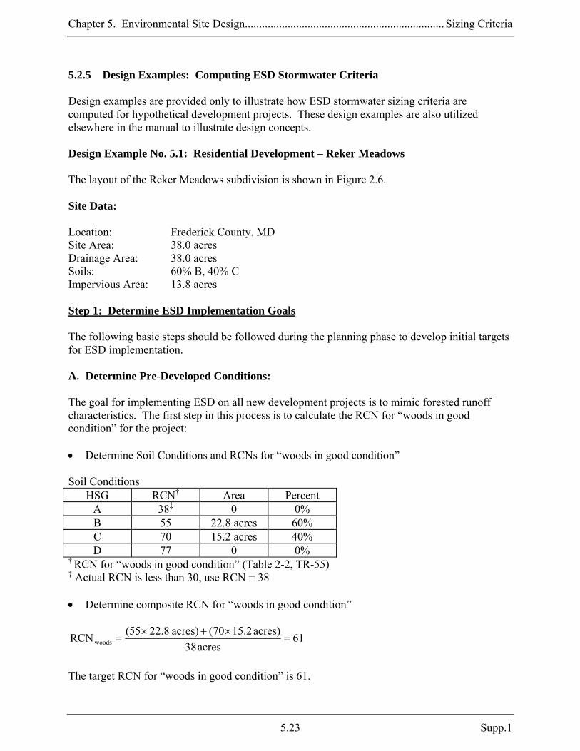
5.2.5 Design Examples: Computing ESD Stormwater Criteria Design examples are provided only to illustrate how ESD stormwater sizing criteria are computed for hypothetical development projects. These design examples are also utilized elsewhere in the manual to illustrate design concepts. Design Example No. 5.1: Residential Development – Reker Meadows The layout of the Reker Meadows subdivision is shown in Figure 2.6. Site Data: Location: Frederick County, MD Site Area: 38.0 acres Drainage Area: 38.0 acres Soils: 60% B, 40% C Impervious Area: 13.8 acres Step 1: Determine ESD Implementation Goals The following basic steps should be followed during the planning phase to develop initial targets for ESD implementation. A. Determine Pre-Developed Conditions: The goal for implementing ESD on all new development projects is to mimic forested runoff characteristics. The first step in this process is to calculate the RCN for “woods in good condition” for the project: • Determine Soil Conditions and RCNs for “woods in good condition” Soil Conditions
HSG RCN† Area Percent A 38‡ 0 0% B 55 22.8 acres 60% C 70 15.2 acres 40% D 77 0 0%
† RCN for “woods in good condition” (Table 2-2, TR-55) ‡ Actual RCN is less than 30, use RCN = 38 • Determine composite RCN for “woods in good condition”
61acres38
)acres2.1570()acres8.2255(RCNwoods =×+×
=
The target RCN for “woods in good condition” is 61.
5.23 Supp.1

Chapter 5. Environmental Site Design...................................................................... Sizing Criteria
B. Determine Target PE Using Table 5.3: PE = Rainfall used to size ESD practices During project planning and preliminary design, site soils and proposed imperviousness are used to determine the target PE for sizing ESD practices to mimic wooded conditions. • Determine Proposed Imperviousness (%I) Proposed Impervious Area (as measured from site plans): 13.8 acres %I = Impervious Area / Drainage Area = 13.8 acres / 38 acres = 36.3%; Because %I is between 35% and 40%, both values should be checked and the more conservative result used to determine target PE. For this example, assume imperviousness is distributed proportionately (60/40) in B and C soils. • Determine PE from Table Using %I = 35% & 40% and B Soils:
PE ≥ 1.8 inches will reduce the RCN to reflect “woods in good condition” for %I = 35% & 40% Using %I = 35% & 40% and C Soils:
Supp. 1 5.24

Chapter 5. Environmental Site Design...................................................................... Sizing Criteria
For %I = 35%, PE ≥ 1.6 inches will reduce the RCN to reflect “woods in good condition” For %I = 40%, PE ≥ 1.8” to achieve the same goal. For this project, PE happens to be the same for both soil groups, therefore use PE = 1.8 inches of rainfall as the target for ESD implementation. C. Compute QE : QE = Runoff depth used to size ESD practices
QE = PE x Rv, where PE = 1.8 inches Rv = 0.05 + (0.009)(I); I = 36.3
= 0.05 + (0.009 x 36.3) = 0.38 QE = 1.8 inches x 0.38 = 0.68 inches ESD targets for the Reker Meadows project: PE = 1.8 inches QE = 0.68 inches By using ESD practices that meet these targets, Rev, WQv, and Cpv requirements will be satisfied. Potential practices could include swales or micro-bioretention to capture and treat runoff from the roads. Likewise, raingardens and disconnection of rooftop runoff could be used to capture and treat runoff from the houses. Step 2: Determine Stormwater Management Requirements After Using ESD For this example, it is assumed that ESD techniques and practices were implemented to treat only 1.2 inches of rainfall (e.g., PE = 1.2 inches) over the entire project. After all efforts to implement ESD practices have been exhausted, the following basic steps should be followed to determine how much additional stormwater management is required. A. Calculate Reduced RCNs PE = Rainfall used to size ESD practices During the planning and design processes, site soils, measured imperviousness, and PE are used to determine reduced RCNs for calculating Cpv requirements. • Determine Reduced RCN for PE = 1.2 inches
5.25 Supp.1
Chapter 5. Environmental Site Design...................................................................... Sizing Criteria
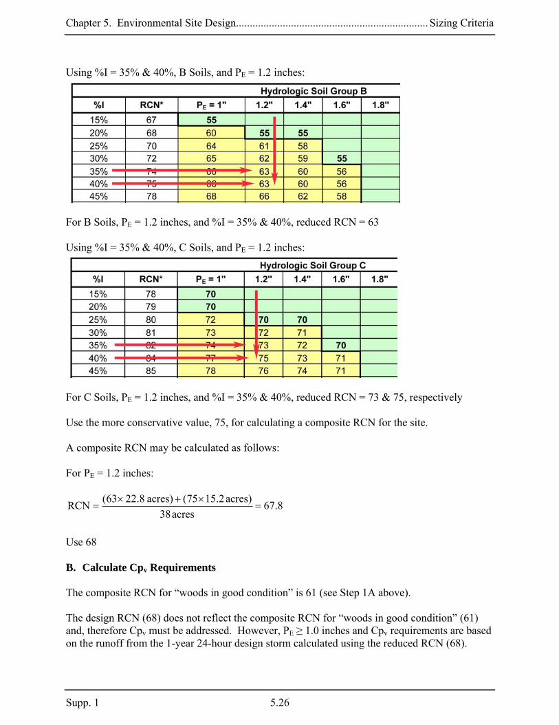
Using %I = 35% & 40%, B Soils, and PE = 1.2 inches:
For B Soils, PE = 1.2 inches, and %I = 35% & 40%, reduced RCN = 63 Using %I = 35% & 40%, C Soils, and PE = 1.2 inches:
For C Soils, PE = 1.2 inches, and %I = 35% & 40%, reduced RCN = 73 & 75, respectively Use the more conservative value, 75, for calculating a composite RCN for the site. A composite RCN may be calculated as follows: For PE = 1.2 inches:
8.67acres38
)acres2.1575()acres8.2263(RCN =×+×
=
Use 68 B. Calculate Cpv Requirements The composite RCN for “woods in good condition” is 61 (see Step 1A above). The design RCN (68) does not reflect the composite RCN for “woods in good condition” (61) and, therefore Cpv must be addressed. However, PE ≥ 1.0 inches and Cpv requirements are based on the runoff from the 1-year 24-hour design storm calculated using the reduced RCN (68).
Supp. 1 5.26

Chapter 5. Environmental Site Design...................................................................... Sizing Criteria
• Compute Cpv Storage Volume When PE ≥ 1.0 inches, Cpv shall be the runoff from the 1-year 24-hour design storm calculated using the reduced RCN. If the reduced RCN for a drainage area reflects “woods in good condition”, then Cpv has been satisfied for that drainage area. Calculate Cpv using design PE = 1.2 inches (RCN = 68): Cpv = Q1 x A where: Q1 is the runoff from the 1-year 24-hour design storm
)S8.0P()S2.0P(Q
2
1 +−
= (Equation 2.3, TR-55, USDA NRCS 1986)
where: P = 1-year 24-hour design storm
S = (1000/RCN) – 10 (Equation 2-4, TR-55) = (1000/68) – 10 = 4.7
inches43.036.676.2
)]7.4x8.0(6.2[)]7.4x2.0(6.2[Q
2
1 ==+−
=
Cpv = 0.43 inches x 38 acres
= 1.36 ac. – ft. or 59, 240 cubic feet
Cpv Storage Requirements for Reker Meadows Additional Cpv Required Rainfall (PE)
(ac-ft) (cu. ft.) Notes:
PE ≥ 1.8 inches NA NA Target PE for RCN = woods PE = 1.2 inches 1.36 59,240 Design PE Conventional Design 1.65 71,875 from Chapter 2 (see page 2.18)
Stormwater management requirements for the Reker Meadows project include using ESD practices to treat 1.2 inches of rainfall and structural practices from Chapter 3 (e.g., shallow wetland) to treat the Cpv of 59,240 cubic feet.
5.27 Supp.1

Chapter 5. Environmental Site Design...................................................................... Sizing Criteria
Design Example No. 5.2: Commercial Development - Claytor Community Center The layout of the Claytor Community Center is shown in Figure 2.9. Site Data: Location: Dorchester County Site Area: 3.0 acres Drainage Area: 3.0 acres Soils: 100% B Impervious Area: 1.9 acres Step 1: Determine ESD Implementation Goals The following basic steps should be followed during the planning phase to develop initial targets for ESD implementation. A. Determine Pre-Developed Conditions: The goal for implementing ESD on all new development projects is to mimic forested runoff characteristics. The first step in this process is to calculate the RCN for “woods in good condition” for the project. • Determine Soil Conditions and RCNs for “woods in good condition” Soil Conditions
HSG RCN† Area Percent A 38‡ 0 0% B 55 3.0 acres 100% C 70 0 acres 0% D 77 0 0%
† RCN for “woods in good condition” (Table 2-2, TR-55) ‡ Actual RCN is less than 30, use RCN = 38 The site is entirely located in HSG B, and the target RCN for “woods in good condition” is 55. B. Determine Target PE Using Table 5.3 PE = Rainfall used to size ESD practices During the project planning and preliminary design, site soils and proposed imperviousness are used to determine target PE for sizing ESD practices to mimic wooded conditions.
Supp. 1 5.28

Chapter 5. Environmental Site Design...................................................................... Sizing Criteria
• Determine Proposed Imperviousness (%I) Proposed Impervious Area (as measured from site plans): 1.9 acres %I = Impervious Area / Drainage Area = 1.9 acres / 3.0 acres = 63.3% Because %I is closer to 65% than 60%, use the more conservative value, 65%. • Determine PE from Table Using %I = 65% & B Soils:
PE ≥ 2.0 inches will reduce the RCN to reflect “woods in good condition” for %I = 65% For this project, use PE = 2.0 inches C. Compute QE : QE = Runoff depth used to size ESD practices QE = PE x Rv, where
PE = 2.0 inches Rv = 0.05 + (0.009)(I); I = 63.3%
= 0.05 + (0.009 x 63.3) = 0.62 QE = 2.0 inches x 0.62 = 1.24 inches
5.29 Supp.1

Chapter 5. Environmental Site Design...................................................................... Sizing Criteria
ESD targets for the Claytor Community Center project: PE = 2.0 inches QE = 1.24 inches By using ESD practices that meet these targets, Rev, WQv, and Cpv requirements will be satisfied. Potential practices could include permeable pavements, micro-bioretention, or landscape infiltration to capture and treat runoff from the rooftops, parking lots, and drive aisles. Step 2. Determine Stormwater Management Requirements After Using ESD For this example, it is assumed that ESD techniques and practices were implemented to treat only 1.6 inches of rainfall (e.g., PE = 1.6 inches) over the entire project. After all efforts to implement ESD practices have been exhausted, the following basic steps should be followed to determine if any additional stormwater management is required. A. Calculate Reduced RCNs PE = Rainfall used to size ESD practices During the design process, site soils, measured imperviousness, and PE are used to determine reduced RCNs for calculating Cpv requirements. • Determine Reduced RCN for PE = 1.6 inches Using %I = 65%, B Soils, and PE = 1.6 inches:
For B Soils, PE = 1.6 inches, and %I = 65%, reduced RCN = 65 B. Calculate Cpv Requirements The RCN for “woods in good condition” = 55 (see Step 1A above).
Supp. 1 5.30

Chapter 5. Environmental Site Design...................................................................... Sizing Criteria
The design RCN (65) does not reflect “woods in good condition” (55) and therefore Cpv must be addressed. However, PE ≥ 1.0 inches, and Cpv is based on the runoff from the 1-year 24-hour design storm calculated using the reduced RCN (65). • Compute Cpv Storage Volume When PE ≥ 1.0 inches, Cpv shall be the runoff from the 1-year 24-hour design storm calculated using the reduced RCN. If the reduced RCN for a drainage area reflects “woods in good condition”, then Cpv has been satisfied for that drainage area.
Calculate Cpv using design PE = 1.6 inches (RCN = 65) Cpv = Q1 x A where: Q1 = runoff from the 1-year 24-hour design storm
)S8.0P()S2.0P(Q
2
1 +−
= (Equation 2.3, TR-55, USDA NRCS 1986)
where: P = 1-year 24-hour design storm S = (1000/RCN) – 10 (Equation 2-4, TR-55)
= (1000/65) – 10 = 5.4
inches42.012.796.2
)]4.5x8.0(8.2[)]4.5x2.0(8.2[Q
2
1 ==+−
=
Cpv = 0.42 inches x 3.0 acres
= 0.105 ac. – ft. or 4,574 cubic feet
Cpv Storage Requirements for Claytor Community Center Additional Cpv Required Rainfall (PE)
(ac-ft) (cu. ft.) Notes:
PE ≥ 2.0 inches NA NA Target PE for RCN = woods PE = 1.6 inches 0.105 4,574 Design PE Conventional Design 0.21 9,150 See Note Below*
*NOTE: Prior to 2009, Cpv was not required on the Eastern Shore. However, an estimated 0.21 ac.-ft (9,150 cubic feet) would have been needed to address Cpv in Design Example No. 2 in Chapter 2. Stormwater management requirements for the Claytor Community Center project include using ESD practices to treat 1.6 inches of rainfall and structural practices from Chapter 3 (e.g., shallow wetland) to treat the Cpv of 4,574 cubic feet.
5.31 Supp.1

Chapter 5. Environmental Site Design...................................................................... Sizing Criteria
Design Example No. 5.3: Multiple Drainage Areas – Pensyl Pointe The layout of the Pensyl Pointe subdivision is shown in Figure 2.12. Site Data: Location: Montgomery County, MD Site Area: 38.0 acres Drainage (DA) 1 Area: 7.6 acres Soils: 60% B, 40% C Impervious Area: 2.25 acres Drainage (DA) 2 Area: 30.4 acres Soils: 60% B, 40% C Impervious Area: 11.55 acres Step 1: Determine ESD Implementation Goals The following basic steps should be followed during the planning phase to develop initial targets for ESD implementation. A. Determine Pre-Developed Conditions: The goal for implementing ESD on all new development sites is to mimic forested runoff characteristics. The first step in this process is to calculate the RCNs for “woods in good condition” for the project. • Determine Soil Conditions and RCNs for “woods in good condition” DA 1 Soil Conditions (DA 1)
HSG RCN† Area Percent A 38‡ 0 0% B 55 4.6 acres 60% C 70 3.0 acres 40% D 77 0 0%
† RCN for “woods in good condition” (Table 2-2, TR-55) ‡ Actual RCN is less than 30, use RCN = 38 • Determine Composite RCN for “woods in good condition” for DA 1
61acres6.7
)acres0.370()acres6.455(RCN woods =×+×
=
Supp. 1 5.32

Chapter 5. Environmental Site Design...................................................................... Sizing Criteria
The target RCN for “woods in good condition” is 61 DA 2 Soil Conditions (DA 2)
HSG RCN† Area Percent A 38‡ 0 0% B 55 18.2 acres 60% C 70 12.2 acres 40% D 77 0 0%
† RCN for “woods in good condition” (Table 2-2, TR-55) ‡ Actual RCN is less than 30, use RCN = 38 Determine Composite RCN for “woods in good condition” for DA 2
61acres4.30
)acres2.1270()acres2.1855(RCN woods =×+×
=
The target RCN for “woods in good condition” is 61 B. Determine Target PE Using Table 5.3: PE = Rainfall used to size ESD practices During the planning and preliminary design processes, site soils and proposed imperviousness are used to determine target PE for sizing ESD practices to mimic wooded conditions. • Determine Proposed Imperviousness (%I) DA 1 Proposed Impervious Area (as measured from site plans): 2.25 acres; %I = Impervious Area / Drainage Area = 2.25 acres / 7.6 acres = 30.0% DA 2 Proposed Impervious Area (as measured from site plans): 11.55 acres; %I = Impervious Area / Drainage Area = 11.55 acres / 30.4 acres = 38.0% Because %I is closer to 40% than 35%, use the more conservative value , 40%, to determine target PE.
5.33 Supp.1
Chapter 5. Environmental Site Design...................................................................... Sizing Criteria
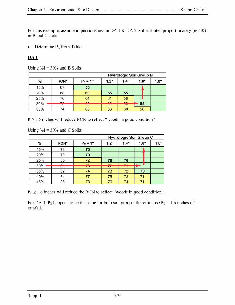
For this example, assume imperviousness in DA 1 & DA 2 is distributed proportionately (60/40) in B and C soils. • Determine PE from Table DA 1 Using %I = 30% and B Soils:
P ≥ 1.6 inches will reduce RCN to reflect “woods in good condition” Using %I = 30% and C Soils:
PE ≥ 1.6 inches will reduce the RCN to reflect “woods in good condition”. For DA 1, PE happens to be the same for both soil groups, therefore use PE = 1.6 inches of rainfall.
Supp. 1 5.34

Chapter 5. Environmental Site Design...................................................................... Sizing Criteria
DA 2 Using %I = 40% and B Soils:
PE ≥ 1.8 inches will reduce the RCN to reflect “woods in good condition”. Using %I = 40% and C Soils:
PE ≥ 1.8 inches will reduce the RCN to reflect “woods in good condition”. For DA 2, PE happens to be the same for both soil groups, therefore use PE = 1.8 inches of rainfall. C. Compute QE: DA 1 QE = Runoff depth used to size ESD practices QE = PE x Rv, where PE = 1.6 inches Rv = 0.05 + (0.009)(I); I = 30.0% = 0.05 + (0.009 x 30.0) = 0.32 QE = 1.6 inches x 0.32 = 0.51 inches
5.35 Supp.1

Chapter 5. Environmental Site Design...................................................................... Sizing Criteria
DA 2 QE = Runoff depth used to size ESD practices QE = PE x Rv, where PE = 1.8 inches Rv = 0.05 + (0.009)(I); I = 38.0% = 0.05 + (0.009 x 38.0) = 0.39 QE = 1.8 inches x 0.39 = 0.70 inches ESD targets for the Pensyl Pointe project: DA 1 DA 2 PE = 1.6 inches PE = 1.8 inches QE = 0.51 inches QE = 0.70 inches By using ESD practices that meet these targets, Rev, WQv, and Cpv requirements will be satisfied. Potential practices could include swales or micro-bioretention to capture and treat runoff from the roads. Likewise, raingardens and disconnection of runoff could be used to capture and treat runoff from the houses. Step 2. Determine Stormwater Management Requirements After Using ESD For this example, it is assumed that ESD techniques and practices were implemented to treat only 1.6 inches of rainfall (e.g., PE = 1.6 inches) over the entire project. After all efforts to implement ESD practices have been exhausted, the following basic steps should be followed to determine if any additional stormwater management is required. A. Calculate Reduced RCNs PE = Rainfall used to size ESD practices During the planning and design processes, site soils, measured imperviousness, and PE are used to determine reduced RCNs for calculating Cpv requirements. • Determine Reduced RCNs for PE = 1.6 inches
Supp. 1 5.36

Chapter 5. Environmental Site Design...................................................................... Sizing Criteria
DA 1 Using %I = 30%, B Soils, and PE = 1.6 inches:
For B Soils, PE = 1.6 inches, and %I = 30%, reduced RCN = 55 (woods in good condition) Using %I = 30%, C Soils, and PE = 1.6 inches:
For C Soils, PE = 1.6 inches, and %I = 30%, reduced RCN = 70 (woods in good condition) Composite RCNs may be calculated as follows: For PE = 1.6 inches:
9.60acres6.7
)acres0.370()acres6.455(RCN =×+×
=
Use 61
5.37 Supp.1
Chapter 5. Environmental Site Design...................................................................... Sizing Criteria
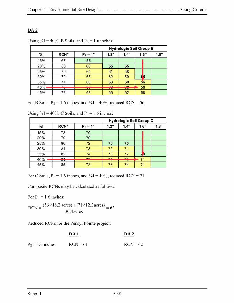
DA 2 Using %I = 40%, B Soils, and PE = 1.6 inches:
For B Soils, PE = 1.6 inches, and %I = 40%, reduced RCN = 56 Using %I = 40%, C Soils, and PE = 1.6 inches:
For C Soils, PE = 1.6 inches, and %I = 40%, reduced RCN = 71 Composite RCNs may be calculated as follows: For PE = 1.6 inches:
62acres4.30
)acres2.1271()acres2.1856(RCN =×+×
=
Reduced RCNs for the Pensyl Pointe project:
DA 1 DA 2 PE = 1.6 inches RCN = 61 RCN = 62
Supp. 1 5.38

Chapter 5. Environmental Site Design...................................................................... Sizing Criteria
B. Calculate Cpv Requirements DA 1 The composite RCN for “woods in good condition” is 61 (see Step 1A above). The design RCN (61) for PE = 1.6 inches reflects “woods in good condition” and therefore Cpv is addressed.
Cpv Storage Requirements for Pensyl Pointe - DA 1 Additional Cpv Required Rainfall (PE)
(ac-ft) (cu. ft.) Notes:
PE ≥ 1.6 inches NA NA Target PE for RCN = woods PE = 1.6 inches NA NA Design PE Conventional Design 0.30 13,070 From Chapter 2 (see page 2.32)
DA 2 The composite RCN for “woods in good condition” is 61 (see Step 1A above). The design RCN (62) does not reflect the composite RCN for “woods in good condition” (61) and Cpv must be addressed. However, PE ≥ 1.0 inches, and Cpv is based on the runoff from the 1-year 24-hour design storm calculated using the reduced RCN (62). Calculate Cpv using design PE = 1.6 inches (RCN = 62) Cpv = Q1 x A Where Q1 is the runoff from the 1-year 24-hour design storm
)S8.0P()S2.0P(Q
2
1 +−
= (Equation 2.3, TR-55, USDA NRCS 1986)
where: P = 1-year 24-hour design storm S = (1000/RCN) – 10 (Equation 2-4, TR-55) = (1000/62) – 10 = 6.1
inches25.048.790.1
)]1.6x8.0(6.2[)]1.6x2.0(6.2[Q
2
1 ==+−
=
Cpv = 0.25 inches x 30.4 acres
= 0.63 ac. – ft. or 27,440 cubic feet
5.39 Supp.1

Chapter 5. Environmental Site Design...................................................................... Sizing Criteria
Supp. 1 5.40
Cpv Storage Requirements for Pensyl Pointe – DA 2 Additional Cpv Required Rainfall (PE)
(ac-ft) (cu. ft.) Notes:
PE ≥ 1.8 inches NA NA Target PE for RCN = woods PE = 1.6 inches 0.63 27,440 Design PE Conventional Design 1.31 57,065 From Chapter 2 (see page 2.33)
Stormwater management requirements for the Pensyl Pointe project include using ESD practices to treat 1.6 inches of rainfall and structural practices from Chapter 3 (e.g., shallow wetland) to treat the Cpv of 27,440 cubic feet.

Chapter 5. Environmental Site Design.............................................................Alternative Surfaces
Section 5.3 Alternative Surfaces An effective method to reduce imperviousness in residential, commercial, and industrial applications is to use more permeable alternatives. Roofs and pavements are often overlooked areas that may be replaced with more permeable surfaces. Green roofs are particularly useful alternatives for reducing impervious cover and provide much needed green space in ultra-urban or high-density developments. Whether made from porous asphalt or concrete, interlocking pavers, or reinforced turfs, permeable pavements are a cost-effective alternative for parking lot and roadway surfaces. Alternative surface variants include:
A-1. Green Roofs A-2. Permeable Pavements A-3. Reinforced Turf
5.41 Supp.1

Chapter 5. Environmental Site Design.............................................................Alternative Surfaces
A-1. Green Roofs Green roofs are alternative surfaces that replace conventional construction materials and include a protective covering of planting media and vegetation. Also known as vegetated roofs, roof gardens, or eco-roofs, these may be used in place of traditional flat or pitched roofs to reduce impervious cover and more closely mimic natural hydrology. Green roofs produce less heat than conventional systems. Therefore, they may be used to help mitigate stormwater impacts and temperature increases caused by new development. There are two basic green roof designs that are distinguished by media thickness and the plant varieties that are used. The more common or “extensive” green roof is a lightweight system where the media layer is between two and six inches thick. This limits plants to low-growing, hardy herbaceous varieties. An extensive green roof may be constructed off-site as a modular system with drainage layers, growing media, and plants installed in interlocking grids. Conventional construction methods may also be used to install each component separately. “Intensive” green roofs have thicker soil layers (eight inches or greater) and are capable of supporting more diverse plant communities including trees and shrubs. A more robust structural loading capacity is needed to support the additional weight of the media and plants. Intensive green roofs are more complex and expensive to design, construct, and maintain, are less commonly used, and are therefore not covered here. Applications: Green roofs may be used to replace most conventional roofs in both new and redevelopment applications in residential, commercial, and industrial projects. Green roofs are particularly useful for reducing impervious cover in ultra-urban or high-density areas as well. Green roofs may also mitigate temperature increases on projects located in thermally sensitive watersheds. Performance: When designed according to the guidance provided below, the rooftop area covered by a green roof will have runoff characteristics more closely resembling grassed or open space areas. The capacity of a green roof to detain runoff is governed by planting media thickness and roof slope or “pitch.” However, the RCNs shown in Table 5.4 below are used to determine how green roofs contribute to addressing the ESD Sizing Criteria. Table 5.4 Effective RCNs for Extensive Green Roofs Roof Thickness (in.): 2 3 4 6 8 Effective RCN: 94 92 88 85 77 Because impermeable liners are an integral component in all systems, green roofs do not provide groundwater recharge. Therefore, additional treatment is needed to compensate for the loss of recharge from rooftop areas. This is equal to Rev for the rooftop area and may be provided in separate infiltration practices or as additional storage within downstream ESD practices.
Supp. 1 5.42

Chapter 5. Environmental Site Design.............................................................Alternative Surfaces
Constraints: The following constraints are critical when considering the use of green roofs to treat stormwater runoff:
Infrastructure: The location of existing and proposed utilities (e.g., HVAC, gutters, downspouts, electricity) will influence the design and construction of green roofs.
Structure: Green roofs are not suitable for use on steep roofs (> 30% or 4:12). Sloped
roofs may require additional measures to prevent sliding and ensure stability. The structure must also be capable of supporting the additional weight (live and dead load) of a green roof. Typical dead load ranges from 8 to 36 lbs/ft2. Live load is a function of rainfall retention (e.g., 1 inch of rain or 10 inches of snow equals 5.2 lbs/ft2). For redevelopment projects and existing buildings, additional measures (e.g., trusses, joists, columns) may be needed for support.
Waterproofing: Materials should be durable under the conditions associated with vegetated
covers. Supplemental barrier layers may be required with waterproofing membranes that may be damaged by plant roots.
Drainage: Building drainage (e.g., gutters, deck drains, scuppers) must be capable of
managing large rainfall events without inundating the roof. Design Guidance: The following conditions should be considered when designing green roofs:
Conveyance: Runoff shall flow through and exit green roof systems in a safe and non-erosive manner. Overflow structures should be capable of passing the 2-year 24-hour design storm without inundating the roof. A semi-rigid, plastic geocomposite drain or mat layer should be included to convey runoff to the building drainage system. Flat roof applications may require a perforated internal network to facilitate drainage of rainfall. Additionally, roof flashing should extend six inches above the media surface and be protected by counter-flashing.
Runoff from adjacent roofs should not drain to the green roof. If bypassing a green roof is impractical, an overflow device (e.g., gutter, deck drain) should be used. All green roofs shall include a waterproofing system or membrane. Materials used should be durable under vegetated cover conditions and resistant to biological and root attack. A supplemental barrier may be needed to protect the waterproofing from plant roots.
5.43 Supp.1

Chapter 5. Environmental Site Design.............................................................Alternative Surfaces
Treatment: Green roof systems shall meet the following conditions:
o Planting media shall be non-soil engineered mixes conforming to the specifications found in Appendix B.4. Media layers should be between two to six inches thick. Dual media systems may be applied where green roof assemblies are four inches or thicker.
o Individual layers (e.g., root barriers, drainage mats, separation geotextiles) shall conform to the specifications found in Appendix B.4.
Figure 5.2 Cutaway of a Typical Green Roof
Structure:
o The roof structure shall be capable of bearing the maximum predicted dead and live loads associated with green roof systems. Standardized media weights and procedures (e.g., ASTM E-2397-05, E-2399-05) shall be used to establish the dead load bearing capacity of the roof.
o Green roofs with pitches steeper than 2:12 shall include supplemental measures (e.g., slope bars, rigid stabilization panels, reinforcing mesh) to enhance stability and prevent media sliding.
Landscaping: Vegetation is critical to the function and appearance of any green roof.
Therefore landscaping plans should be provided according to the guidance in Appendix B.4.
Supp. 1 5.44

Chapter 5. Environmental Site Design.............................................................Alternative Surfaces
A vigorous, drought-tolerant vegetative cover should be established using varieties of sedum, delosperma, or similar varieties native or suitable for growth in Maryland.
Construction Criteria: The following items should be addressed during construction of projects with green roofs:
Waterproofing Installation: Measures shall be taken to prevent membrane damage during green roof installation. Any flaws, irregularities, or conditions that may cause leaks or roof damage shall be identified and repaired. The waterproofing membrane should be visually inspected and tested for water tightness prior to installation of the planting mix.
Slope Stabilization Measures: Where required, slope stabilization measures should be
placed prior to green roof installation. In some situations, slope stabilization may be integrated into the roof structure.
Green Roof Installation: Green roof systems should be installed according to the
manufacturer’s instructions. Generally, root-barrier layers, walkways, and irrigation systems should be installed first.
Inspection:
The following certifications shall be required during construction:
o Prior to placement of the waterproofing, drainage, and treatment materials, certification that the constructed roof meets the load bearing capacity specified on the approved plans.
o After its installation and prior to placement of the planting media and stock, certification regarding the water tightness of the waterproofing membrane.
Regular inspections shall be made during the following stages of construction:
o During placement of the waterproofing membrane. o During placement of the drainage system. o During placement of the planting media. o Upon installation of the plant material. o Before issuing use and occupancy approvals (new construction only). o During the second growing season to ensure adequate vegetation survival.
Maintenance Criteria: Green roofs require annual maintenance to ensure optimum performance. Typically, eighteen months are needed to establish adequate initial plant growth. Periodic irrigation may be needed during this time and basic weeding, fertilizing, and in-fill planting may be required as well. After plants are established, the roof should be inspected and light weeding performed once or twice per year.
5.45 Supp.1
Chapter 5. Environmental Site Design.............................................................Alternative Surfaces
A-2. Permeable Pavements Permeable pavements are alternatives that may be used to reduce imperviousness. While there are many different materials commercially available, permeable pavements may be divided into three basic types: porous bituminous asphalt, pervious concrete, and permeable interlocking concrete pavements. Permeable pavements typically consist of a porous surface course and open graded stone base/subbase or sand drainage system. Stormwater drains through the surface course, is captured in the drainage system, and infiltrates into the surrounding soils. Permeable pavements significantly reduce the amount of impervious cover, provide water quality and groundwater recharge benefits, and may help mitigate temperature increases. Applications: Permeable pavements are effective for reducing imperviousness in pedestrian pavements, parking lots, driveways, plazas, and access roads. They may be used in both new and redevelopment applications in residential, commercial, and industrial projects. Permeable pavements are particularly useful in high-density areas where space is limited. Performance: When designed according to the guidance provided below, areas covered by permeable pavements will have runoff characteristics more closely resembling vegetated areas. The capacity of permeable pavements to capture and detain runoff is governed by the storage capacity, compaction of the soil subgrade, and in-situ soil properties. Consequently, RCN’s applied to these systems vary with individual design characteristics. The effective RCN’s shown in Table 5.5 are used when addressing the ESD Sizing Criteria. Constraints: The following constraints are critical when considering the use of permeable pavements to capture and treat stormwater runoff:
Space: The size and distribution of paved surfaces within a project must be considered early during planning and design. Permeable pavements should not be used in areas where there are risks for foundation damage, basement flooding, interference with subsurface sewage disposal systems, or detrimental impacts to other underground structures.
Topography: Runoff should sheetflow across permeable pavements. Pavement surfaces
should be gradual (≤ 5%) to prevent ponding of water on the surface and within the subbase.
Soils: Sandy and silty soils are critical to successful application of permeable pavements. The HSG should be A, B or C.
Supp. 1 5.46

Chapter 5. Environmental Site Design.............................................................Alternative Surfaces
Subsurface water conditions (e.g., water table) will help determine the stone reservoir thickness used. The probability of practice failure increases if the reservoir intercepts groundwater. Therefore, subbase inverts should be above local groundwater tables.
Drainage Area: Permeable pavements are an at-source practice for reducing the effects of
impervious cover and addressing ESD criteria. As the impervious area draining to each practice increases, practice effectiveness weakens. Therefore, runoff from adjacent areas (or “run-on”) should be limited.
Hotspot Runoff: Permeable pavements should not be used to treat hotspots that generate
higher concentrations of hydrocarbons, trace metals, or toxicants than are found in typical stormwater runoff and may contaminate groundwater.
Structure: Most permeable alternatives have a lower load bearing capacity than
conventional pavements. Therefore, applications should be limited to locations that do not receive heavy vehicle traffic and where sub soils are not compacted.
Operation: Permeable pavements are highly susceptible to clogging and subject to owner
neglect. Individual owners need to be educated to ensure that proper maintenance and winter operation activities will allow the system to function properly.
Design Guidance: The following conditions should be considered when designing permeable pavements:
Conveyance: Runoff shall flow through and exit permeable pavements in a safe and non-erosive manner. Permeable pavements should be designed off-line whenever possible. Runoff from adjacent areas should be diverted to a stable conveyance system. If bypassing these areas is impractical, then runoff should sheetflow onto permeable pavements.
Pavement surfaces shall have a permeability of eight inches per hour or greater to convey water into the subbase rapidly. The slope of the permeable pavement shall be no greater than 5%. Any grade adjustments requiring fill should be accomplished using the subbase material. Permeable pavements may be placed in sloped areas by terracing levels along existing contours. Pavement systems should include an alternate mode for runoff to enter the subbase reservoir. In curbless designs, this may consist of a two-foot wide stone edge drain. Raised inlets may be required in curbed applications. The bottom of the subbase shall be level to enhance distribution and reduce ponding within the reservoir. A network of perforated pipes may be used to uniformly distribute runoff over the bed bottom. Perforated pipes may also be used to connect structures (e.g., cleanouts, inlets) located within the permeable pavement section.
5.47 Supp.1

Chapter 5. Environmental Site Design.............................................................Alternative Surfaces
All permeable pavements shall be designed to ensure that water surface elevations for the 10-year 24 hour design storm do not rise into the pavement to prevent freeze/thaw damage to the surface. Designs should include overflow structures like overdrains, inlets, edge drains, or similar devices that will convey excess runoff safely to a stable outfall.
Treatment: All permeable pavement systems shall meet the following conditions: o Applications that exceed 10,000 ft2 shall be designed as infiltration practices using
the design methods outlined in Appendix D.13 for infiltration trenches. A porosity (n) of 30% and an effective area of the trench (At) equal to 30% of the pavement surface area shall be used.
o A subbase layer of a clean, open graded, washed aggregate with a porosity (n) of 30% (1.5” to 2” stone is preferred) shall be used below the pavement surface. The subbase may be 6”, 9” or 12” thick.
o Filter cloth shall not be used between the subbase and soil subgrade. If needed, a 12” layer of washed concrete sand or pea gravel (⅛” to ⅜” stone) may be used to act as a bridging layer between the subbase reservoir and subsurface soils.
Table 5.5 Effective RCNs for Permeable Pavements Hydrologic Soil Group
Subbase A B C D
6” 761 841 932 ─ 9” 623 653 773 ─ 12” 40 55 70 ─
1. Design shall include 1 - 2” min. overdrain (inv. 2” below pavement base) per 750 s.f. of pavement area. 2. Design shall include 1 - 2” min. overdrain (inv. 2” below pavement base) per 600 s.f. of pavement area 3. Design shall include 1 - 3” min. overdrain (inv. 3” below pavement base) and a ½” underdrain at subbase invert.
Soils:
o Permeable pavements shall not be installed in HSG D or on areas of compacted fill.
Underlying soil types and condition shall be field-verified prior to final design. o For applications that exceed 10,000 ft2, underlying soils shall have an infiltration
rate ( f ) of 0.52 in/hr or greater. This rate may be initially determined from NRCS soil textural classification and subsequently confirmed by geotechnical tests in the field as required in Chapter 3.3.1.
o The invert of the subbase reservoir shall be at least four feet above (two feet on the lower Eastern Shore) the seasonal high water table.
Supp. 1 5.48
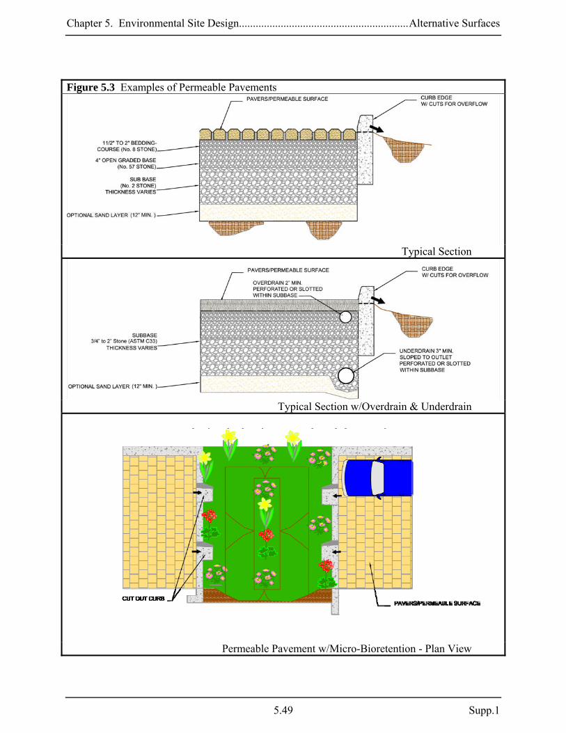
Chapter 5. Environmental Site Design.............................................................Alternative Surfaces
Figure 5.3 Examples of Permeable Pavements
Typical Section
Typical Section w/Overdrain & Underdrain
Permeable Pavement w/Micro-Bioretention - Plan View
5.49 Supp.1

Chapter 5. Environmental Site Design.............................................................Alternative Surfaces
Setbacks:
o Permeable pavements shall be located down gradient of building structures and be setback at least 10 feet from buildings, 50 feet from confined water supply wells, 100 feet from unconfined water supply wells, and 25 feet from septic systems.
o Permeable pavements should also be sized and located to meet minimum local requirements for underground utility clearance.
Structure: All permeable pavement systems shall be capable of bearing the anticipated
vehicle and traffic loads. Pavement systems conforming to the specifications found in Appendix B.4 should be structurally stable for typical (e.g., light duty) applications.
Landscaping: Permeable pavement shall be identified on landscaping plans. Trees and
shrubs should not be located adjacent to asphalt and concrete if damage by root penetration and clogging from leaves is a concern.
Construction Criteria: The following items should be addressed during construction of projects with permeable pavement:
Erosion and Sediment Control: Final grading for installation should not take place until the surrounding site is stabilized. If this cannot be accomplished, runoff from disturbed areas shall be diverted around proposed pavement locations.
Soil Compaction: Sub soils shall not be compacted. Construction should be performed with
lightweight, wide tracked equipment to minimize compaction. Excavated materials should be placed in a contained area.
Distribution Systems: Overdrain, underdrain, and distribution pipes shall be checked to
ensure that both the material and perforations meet specifications (see Appendix B.4). The upstream ends of pipes should be capped prior to installation. All underdrain or distribution pipes used should be installed flat along the bed bottom.
Subbase Installation: Subbase aggregate shall be clean and free of fines. The subbase
shall be placed in lifts and lightly rolled according to the specifications (see Appendix B.4).
Supp. 1 5.50

Chapter 5. Environmental Site Design.............................................................Alternative Surfaces
Inspection:
Regular inspections shall be made during the following stages of construction:
o During excavation to subgrade. o During placement and backfill of any drainage or distribution system(s). o During placement of the crushed stone subbase material. o During placement of the surface material. o Upon completion of final grading and establishment of permanent stabilization.
Maintenance Criteria: The following procedures should be considered essential for maintaining permeable pavement systems:
Pavements should be used only where regular maintenance can be performed. Maintenance agreements should clearly specify how to conduct routine tasks to ensure long-term performance.
Pavement surfaces should be swept and vacuumed to reduce sediment accumulation and
ensure continued surface porosity. Sweeping should be performed at least twice annually with a commercial cleaning unit. Washing systems and compressed air units should not be used to perform surface cleaning.
Drainage pipes, inlets, stone edge drains, and other structures within or draining to the
subbase should be cleaned out at regular intervals.
Trucks and other heavy vehicles can grind dirt and grit into the porous surfaces, leading to clogging and premature failure. These vehicles should be prevented from tracking and spilling material onto the pavement.
Deicers should be used in moderation. When used, deicers should be non-toxic and organic
and can be applied either as calcium magnesium acetate or as pretreated salt. Snow plowing should be done carefully with blades set one-inch higher than normal. Plowed snow piles and snowmelt should not be directed to permeable pavement.
5.51 Supp.1
Chapter 5. Environmental Site Design.............................................................Alternative Surfaces
A-3. Reinforced Turf Reinforced turf consists of interlocking structural units with interstitial areas for placing gravel or growing grass. These systems are suitable for light traffic loads and are commonly used for emergency vehicle access roads and overflow or occasionally used parking. Applications: Reinforced turf is effective for reducing imperviousness in parking lots, driveways, plazas, and access roads in both new and redevelopment applications in residential, commercial, and industrial projects. It is particularly useful in high-density areas where space is limited. Because reinforced turf is an open load-bearing matrix within a vegetated or gravel surface, runoff characteristics are similar to open space in good condition or gravel. Performance: When designed according to the guidance provided below, reinforced turf areas are considered as permeable surfaces. Post development RCN’s for reinforced turf applications should reflect the surfacing material used (e.g., “open space in good condition” for grass). Constraints: The following constraints are critical when considering the use of reinforced turf to capture and treat stormwater runoff:
Space: Reinforced turf works best when designed as small areas or in a series of narrow strips. The size and distribution of these surfaces within a project must be considered early during planning and design.
Topography: Runoff should sheetflow onto and across reinforced turf. Contributing
drainage slopes should be moderate (≤ 5%). If slopes are too steep, then level-spreading devices may be needed to redistribute flow. Turf surfaces should be gradual (≤ 4%) to prevent ponding of water within the subbase.
Soils: Reinforced turf may be used in all soils but works best in sandy soils.
Drainage Area: Reinforced turf is an at source practice for reducing impervious cover. As
the impervious area draining to each application increases, effectiveness weakens. Therefore, runoff from adjacent areas should be limited.
Hotspot Runoff: Reinforced turf should not be used to treat hotspots that generate higher
concentrations of hydrocarbons, trace metals, or toxicants than are found in typical stormwater runoff and may contaminate groundwater.
Supp. 1 5.52
Chapter 5. Environmental Site Design.............................................................Alternative Surfaces
Structure: Most reinforced turf has a lower load bearing capacity than conventional pavements. Therefore, applications should be limited to locations that do not receive heavy vehicle traffic and where sub soils are not compacted.
Operation: Reinforced turf is susceptible to owner neglect. Individual owners need to be
educated to ensure that proper maintenance and winter operation activities will allow the system to function properly.
Design Guidance: The following conditions should be considered when designing reinforced turf:
Conveyance: Runoff shall enter, flow through, and exit reinforced turf in a safe and non-erosive manner. Reinforced turf should be designed off-line whenever possible. The slope of reinforced turf shall be at least 1% but no greater than 5%. Reinforced turf applications may be placed in sloped areas by terracing levels along existing contours.
Treatment: All reinforced turf systems shall meet the following conditions: o A subbase layer of clean, open graded stone or sand with a porosity (n) of 30% (1.5”
to 2” stone is preferred) shall be used below the turf surface. The subbase may be 6” to 12” thick.
Soils:
o Reinforced turf shall not be placed on areas of compacted fill. o Reinforced turf should be installed in HSG A. B, or C for maximum effiectiveness.
Setbacks:
o Reinforced turf should be sized and located to meet minimum local requirements for
underground utility clearance.
Structure: Reinforced turf shall be capable of bearing the anticipated vehicle and traffic loads. Systems conforming to the specifications found in Appendix B.4 should be structurally stable for typical (e.g., light duty) applications.
Landscaping: Reinforced turf shall be identified on landscaping plans. Trees and shrubs
should not be located adjacent to reinforced turf where damage by root penetration is a concern.
5.53 Supp.1

Chapter 5. Environmental Site Design.............................................................Alternative Surfaces
Supp. 1 5.54
Construction Criteria: The following items should be addressed during construction of projects with reinforced turf:
Erosion and Sediment Control: Final grading for installation shall not take place until the surrounding site is stabilized. If this cannot be accomplished, runoff from disturbed areas shall be diverted around proposed locations.
Soil Compaction: Sub soils shall not be compacted. Construction should be performed with
lightweight, wide tracked equipment to minimize compaction. Excavated materials should be placed in a contained area.
Filter Cloth: Filter cloth shall not be used between the subbase and sub soils.
Subbase Installation: The subbase shall be placed in lifts and lightly rolled according to
the specifications (see Appendix B.4). Subbase aggregate should be clean, washed, and free of fines.
Inspection:
Regular inspections shall be made during the following stages of construction:
o During excavation to sub grade. o During placement of the subbase material. o During placement of the surface material. o Upon completion of final grading and establishment of permanent stabilization.
Maintenance Criteria: The following procedures should be considered essential for maintaining reinforced turf:
Reinforced turf should be used only where regular maintenance can be performed. Maintenance agreements should clearly specify how to conduct routine tasks to ensure long-term performance of these systems.
Drainage pipes, inlets, stone edge drains, and other structures within or draining to the
subbase should be cleaned out at regular intervals.
Trucks and other heavy vehicles can damage the interlocking matrix, leading to premature failure. These vehicles should be prevented from driving onto the turf.
Reinforced turf should be mown regularly and clippings removed from the application area.
Chapter 5. Environmental Site Design.............................Nonstructural and Micro-Scale Practices
Section 5.4 Treatment Using Nonstructural and Micro-Scale Practices 5.4.1 Introduction Disconnecting impervious cover and treating urban runoff closer to its source are the next steps in the design process for implementing ESD. Using nonstructural techniques (e.g., disconnection of rooftop runoff, sheetflow to conservation areas) and micro-scale practices (e.g., rain gardens, bio-swales) throughout a development is an effective way to accomplish this goal. Nonstructural practices may be used to disconnect impervious cover and direct runoff over vegetated areas to promote overland filtering and infiltration. Micro-scale practices are useful for capturing and treating runoff near the source. Whether runoff is directed over permeable areas or captured in small water quality treatment practices, there are reductions in both volume and pollutants delivered to receiving streams. Accordingly, these practices may be used to address the ESD sizing criteria when designed and implemented properly. Nonstructural and micro-scale practices are an integral part of the ESD stormwater management plans. Therefore, the use of these practices shall be documented at the concept, site development, and final design stages and verified with “as-built” certification. If practices are not implemented as planned, then volumes used to design structural practices shall be increased appropriately to meet the ESD sizing criteria.
5.55 Supp.1

Chapter 5. Environmental Site Design............................Nonstructural and Micro-Scale Practices
5.4.2 Nonstructural Practices Nonstructural practices combine relatively simple features, grading, and landscaping to divert runoff into vegetated areas and away from conventional storm drain systems. Runoff flows over these areas, filters through the vegetation, and soaks into the ground. Runoff should be conveyed as sheetflow into and through these areas. As depth and velocity of flow increase, runoff concentrates and the ability of vegetation to filter and detain runoff diminishes rapidly. Consequently, requirements and conditions for nonstructural practices reflect the need to maintain sheetflow conditions. Nonstructural practices include:
N-1. Disconnection of Rooftop Runoff N-2. Disconnection of Non-Rooftop Runoff N-3. Sheetflow to Conservation Areas
Supp. 1 5.56

Chapter 5. Environmental Site Design.............................Nonstructural and Micro-Scale Practices
N-1. Disconnection of Rooftop Runoff Rooftop disconnection involves directing flow from downspouts onto vegetated areas where it can soak into or filter over the ground. This disconnects the rooftop from the storm drain system and reduces both runoff volume and pollutants delivered to receiving waters. To function well, rooftop disconnection is dependent on several site conditions (e.g., flow path length, soils, slopes). Applications: There are many opportunities for disconnecting rooftops in both new and redevelopment designs. Runoff may be directed to undisturbed natural areas (e.g., vegetated buffers) or landscaped areas (e.g., lawns, grass channels). Rooftop disconnection is possible in commercial, industrial, and residential settings given the constraints listed below. Performance: The PE values shown in Table 5.6 may be applied to the ESD sizing criteria when the contributing rooftop area is adequately disconnected. Rev requirements (see Chapter 2) are also addressed when the PE from Table 5.6 meets or exceeds the soil specific recharge factor listed in Section 2.2. Constraints: The following constraints are critical when considering the use of rooftop disconnection to capture and treat stormwater runoff:
Space: A permeable, vegetated treatment area equal to the flow path length must be available down gradient from the downspout to effectively disconnect rooftop runoff. Additional treatment using micro-scale practices may be used to fully meet PE requirements.
Topography: Runoff must be conveyed as sheetflow from the downspout and across open
areas to maintain proper disconnection. Level spreaders may be needed at the downspout to dissipate flow. Additionally, disconnected downspouts should be located on gradual slopes (≤ 5%) and directed away from buildings to both maintain sheetflow and prevent water damage to basements and foundations. If slopes are too steep (> 5%), a series of terraces or berms may be required to maintain sheetflow. These terraces may be readily constructed of landscaping stones, timber, or earthen berms.
Soils: Downspout disconnections work best in undisturbed, sandy soils that allow runoff to
infiltrate. Clayey soils or soils that have been compacted by construction equipment greatly reduce the effectiveness of this practice and soil amendments may be needed.
5.57 Supp.1
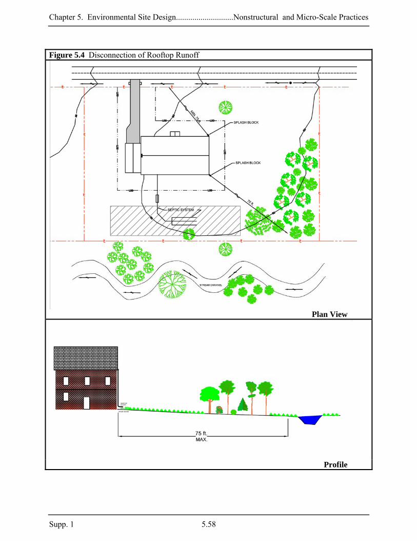
Chapter 5. Environmental Site Design............................Nonstructural and Micro-Scale Practices
Figure 5.4 Disconnection of Rooftop Runoff
Plan View
Profile
Supp. 1 5.58

Chapter 5. Environmental Site Design.............................Nonstructural and Micro-Scale Practices
Drainage Area: The rooftop area to each downspout should be small enough to prevent concentration of flow within the permeable treatment area. Disconnections may not be feasible for large rooftops or those with a limited number of downspouts.
Reconnections: Disconnections are ineffective if runoff flows onto impervious areas located
directly below the downspout. This practice may not be feasible if there are large areas of imperviousness close to downspouts.
Design Guidance: The following conditions should be considered when designing rooftop disconnections:
Conveyance: Runoff from disconnected downspouts shall drain in a safe and non-erosive manner through vegetated areas to the property line or downstream BMP.
Treatment: Disconnections shall meet the following conditions:
o A pervious area at least 15 feet long (12 feet for Eastern Shore projects) shall be
available down gradient of disconnected downspouts. The length of the disconnection flow path may be increased up to 75 feet to address larger values of PE as shown in Table 5.6.
o Disconnections shall be located on an average slope of 5% or less. Terraces, berms, or similar grade controls may be used where average slopes exceed 5%.
o The drainage area to each disconnected downspout shall be 500 ft2 or less. o Disconnected downspouts shall be at least 10 ft. from the nearest impervious surface
of similar or lower elevation to prevent reconnection. Table 5.6. ESD Sizing Factors for Rooftop Disconnection
Disconnection Flow Path Length (ft.) Western
Shore 15 30 45 60 75
Eastern Shore 12 24 36 48 60
PE (in.) = 0.2 0.4 0.6 0.8 1.0
Landscaping: Areas receiving disconnected rooftop runoff shall be identified and notations related to grading and construction operations included on the landscaping plans. Disconnections should be directed over HSG A, B, or C (e.g., sands, sandy loams, loams). HSG D or soils that are compacted by construction equipment may need to be tilled and/or amended to increase permeability. Groundcover should be provided after any soil amendments are used. Turf grass is the most common groundcover in residential applications. However, trees and shrubs as well as other herbaceous plants will enhance infiltration and evapotranspiration of runoff.
5.59 Supp.1

Chapter 5. Environmental Site Design............................Nonstructural and Micro-Scale Practices
Construction Criteria: The following items should be addressed during the construction of projects with planned rooftop disconnections:
Erosion and Sediment Control: Erosion and sediment control practices (e.g., sediment traps) shall not be located in vegetated areas receiving disconnected runoff.
Site Disturbance: Construction vehicles and equipment should avoid areas receiving
disconnected runoff to minimize disturbance and compaction. Should areas receiving disconnected runoff become compacted, scarifying the surface or rototilling the soil to a depth of four to six inches shall be performed to ensure permeability. Additionally, amendments may be needed for tight, clayey soils.
Inspection: A final inspection shall be conducted before use and occupancy approval to ensure that sizing for treatment areas have been met and permanent stabilization has been established. Maintenance Criteria: Maintenance of areas receiving disconnected runoff is generally no different than that required for other lawn or landscaped areas. The areas receiving runoff should be protected from future compaction (e.g., by planting trees or shrubs along the perimeter). In commercial areas, foot traffic should be discouraged as well.
Supp. 1 5.60
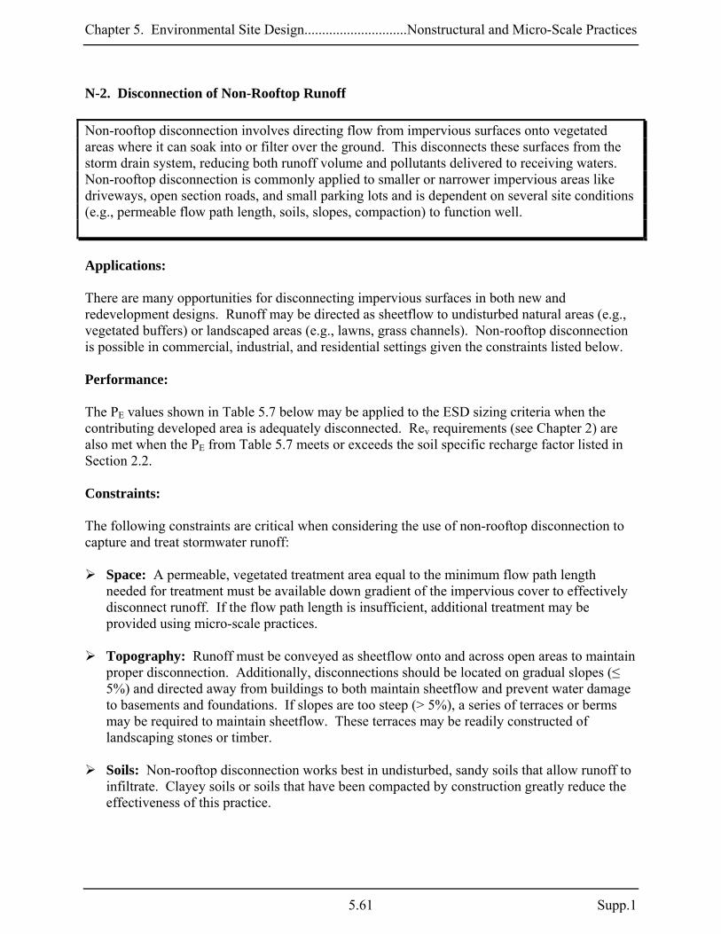
Chapter 5. Environmental Site Design.............................Nonstructural and Micro-Scale Practices
N-2. Disconnection of Non-Rooftop Runoff Non-rooftop disconnection involves directing flow from impervious surfaces onto vegetated areas where it can soak into or filter over the ground. This disconnects these surfaces from the storm drain system, reducing both runoff volume and pollutants delivered to receiving waters. Non-rooftop disconnection is commonly applied to smaller or narrower impervious areas like driveways, open section roads, and small parking lots and is dependent on several site conditions (e.g., permeable flow path length, soils, slopes, compaction) to function well. Applications: There are many opportunities for disconnecting impervious surfaces in both new and redevelopment designs. Runoff may be directed as sheetflow to undisturbed natural areas (e.g., vegetated buffers) or landscaped areas (e.g., lawns, grass channels). Non-rooftop disconnection is possible in commercial, industrial, and residential settings given the constraints listed below. Performance: The PE values shown in Table 5.7 below may be applied to the ESD sizing criteria when the contributing developed area is adequately disconnected. Rev requirements (see Chapter 2) are also met when the PE from Table 5.7 meets or exceeds the soil specific recharge factor listed in Section 2.2. Constraints: The following constraints are critical when considering the use of non-rooftop disconnection to capture and treat stormwater runoff:
Space: A permeable, vegetated treatment area equal to the minimum flow path length needed for treatment must be available down gradient of the impervious cover to effectively disconnect runoff. If the flow path length is insufficient, additional treatment may be provided using micro-scale practices.
Topography: Runoff must be conveyed as sheetflow onto and across open areas to maintain
proper disconnection. Additionally, disconnections should be located on gradual slopes (≤ 5%) and directed away from buildings to both maintain sheetflow and prevent water damage to basements and foundations. If slopes are too steep (> 5%), a series of terraces or berms may be required to maintain sheetflow. These terraces may be readily constructed of landscaping stones or timber.
Soils: Non-rooftop disconnection works best in undisturbed, sandy soils that allow runoff to
infiltrate. Clayey soils or soils that have been compacted by construction greatly reduce the effectiveness of this practice.
5.61 Supp.1

Chapter 5. Environmental Site Design............................Nonstructural and Micro-Scale Practices
Drainage Area: The impervious area to each discharge location should be small enough to prevent flow concentration onto permeable treatment areas. Disconnections may not be feasible for large blocks of impervious cover or areas with limited discharge points.
Hotspot Runoff: Disconnections should not be used to treat hotspots that generate higher
concentrations of hydrocarbons, trace metals, or toxicants than are found in typical stormwater runoff and may contaminate groundwater.
Design Guidance: The following conditions should be considered when designing non-rooftop disconnections:
Conveyance: Runoff from disconnected areas shall drain in a safe and non-erosive manner through vegetated areas to the property line or downstream BMP. A 1 to 2 foot wide gravel (typ. No. 67 stone) transition strip should be provided from the disconnected area to the vegetated area to assure that runoff will flow in a safe and non-erosive manner.
Treatment: Disconnections shall meet the following conditions:
o The flow path or “disconnection” through vegetated areas shall be at least 10 feet
and shall not exceed 75 feet. The flow path may be increased to address larger values of PE to a maximum of 1 inch as shown in Table 5.7.
o The maximum contributing impervious flow path length shall be 75 feet, and the maximum contributing pervious flow path shall be 150 feet.
o Disconnections shall be located on an average slope of 5% or less. Terraces, berms, or similar grade controls may be used where average slopes exceed 5%.
o The drainage area to each disconnection shall be 1,000 ft2 or less. o Disconnections shall be at least 10 ft. from the nearest impervious surface of similar
or lower elevation to prevent reconnection. Table 5.7. ESD Sizing Factors for Non-Rooftop Disconnection
Ratio of Disconnection Length to Contributing Length Impervious
Ratio 0.2:1 0.4:1 0.6:1 0.8:1 1:1
Pervious Ratio 0.1:1 0.2:1 0.3:1 0.4:1 0.5:1
PE (in.) = 0.2 0.4 0.6 0.8 1.0
Landscaping: Areas receiving disconnected runoff shall be identified and notations related to grading and construction operations included on the landscaping plans. Disconnections should be directed over HSG A, B, or C (e.g., sands, sandy loams, loams). HSG D and soils that are compacted by construction equipment may need to be tilled and/or amended to increase permeability. Groundcover vegetation should be provided after any soil
Supp. 1 5.62

Chapter 5. Environmental Site Design.............................Nonstructural and Micro-Scale Practices
amendments are used. Turf grass is the most common groundcover in residential applications. Trees and shrubs as well as other herbaceous plants will enhance infiltration and evapotranspiration of runoff.
Construction Criteria: The following should be addressed during construction of projects with non-rooftop disconnections:
Erosion and Sediment Control: Erosion and sediment control practices (e.g., sediment traps) shall not be located in areas designated for non-rooftop disconnections.
Site Disturbance: To minimize disturbance and compaction, construction vehicles and
equipment should avoid areas receiving disconnected runoff. Should areas receiving disconnected runoff become compacted, scarifying the surface or rototilling the soil to a depth of four to six inches shall be performed to ensure permeability. Additionally, amendments may be needed for tight, clayey soils.
Inspection: A final inspection shall be conducted before use and occupancy approval to ensure that adequate treatment areas and permanent stabilization has been established. Maintenance Criteria: Maintenance of areas receiving disconnected runoff is generally no different than that required for other lawn or landscaped areas. The areas receiving runoff should be protected from future compaction (e.g., by planting trees or shrubs along the perimeter). In commercial areas, high foot traffic should be discouraged as well.
5.63 Supp.1
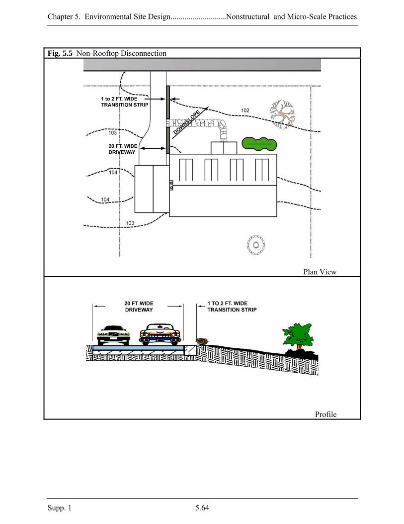
Chapter 5. Environmental Site Design............................Nonstructural and Micro-Scale Practices
Fig. 5.5 Non-Rooftop Disconnection
Plan View
Profile
Supp. 1 5.64
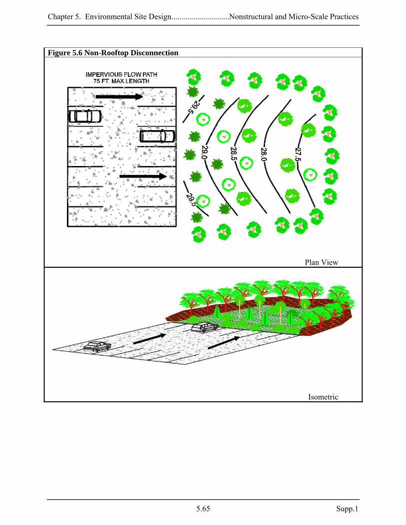
Chapter 5. Environmental Site Design.............................Nonstructural and Micro-Scale Practices
Figure 5.6 Non-Rooftop Disconnection
Plan View
Isometric
5.65 Supp.1

Chapter 5. Environmental Site Design............................Nonstructural and Micro-Scale Practices
N-3. Sheetflow to Conservation Areas Stormwater runoff is effectively treated when flow from developed land is directed to adjacent natural areas where it can soak into or filter over the ground. To function well, this practice is dependent on several site conditions (e.g., buffer size, contributing flow path length, slopes, compaction). Applications: Sheetflow to conservation areas can be used in most development situations provided that site conditions allow implementation. This practice may be used wherever existing stream buffers and other natural areas are protected, expanded, or created during project planning and stormwater runoff may be directed into them, given the constraints listed below. Performance: The PE values shown in Table 5.8 may be applied to the ESD sizing criteria when runoff from developed areas is directed into a conservation area meeting the criteria below. Rev requirements (see Chapter 2) are also met for the contributing drainage area. Constraints: The following constraints are critical when considering the use of sheetflow to conservation areas to treat stormwater runoff:
Space: Conservation areas need to be wide enough to effectively treat runoff and protect natural resources. Flow path lengths from impervious and pervious areas should be minimized to prevent concentration and erosive conditions.
Topography: Runoff should enter conservation areas as sheetflow to enhance performance
and prevent erosion. If slopes are too steep to maintain sheetflow (> 5%), then level-spreading devices will be needed to redistribute flow prior to entering designated buffers.
Hotspot Runoff: Conservation areas should not be used to treat hotspots that generate
higher concentrations of hydrocarbons, trace metals, or toxicants than are found in typical stormwater runoff and may contaminate groundwater.
Easements: Public maintenance access and formal, legal protection are essential for long-
term viability of conservation areas. Acceptable conservation easements, vegetation management plans, or other enforceable instruments are required to prevent encroachment by surrounding landowners minimize invasive or noxious plant growth, and protect conservation areas.
Supp. 1 5.66

Chapter 5. Environmental Site Design.............................Nonstructural and Micro-Scale Practices
Design Guidance: The following conditions should be considered when designing sheetflow to conservation areas:
Conveyance: Runoff from contributing areas shall sheetflow into conservation areas. Either the average contributing overland slope should be 5% or less or a level-spreading device must be used. A boundary spreader, gravel diaphragm, or infiltration berm should be located along the upstream perimeter of the conservation area to diffuse flows from larger storms.
Treatment: Designs using sheetflow to conservation areas shall meet the following
conditions:
o Conservation areas shall be 20,000 square feet or larger to be accepted for ESD purposes.
o The minimum effective width for conservation areas shall be 50 feet. Conservation area widths may be increased to address larger values of PE as shown in Table 5.8.
o The maximum PE applied to conservation areas shall be 1.0 inch. o Conservation areas may include existing natural resources, created or restored
resources, or a combination of both.
Table 5.8. Sheetflow to Conservation Area Sizing Factors Min. Width (ft) = 50 75 100
PE (in.) = 0.6 0.8 1.0
Example: An existing wooded area (60 ft. wide by 250 ft. long) is placed in a conservation easement and identified as a possible area for treating stormwater runoff. While the effective width (60 ft.) is sufficient to treat the area, 15,000 square feet is less than the 20,000 square foot minimum. To meet the minimum area requirement, the conservation area will then be expanded an additional 20 feet in width through reforestation. This increases the conservation area to 20,000 square feet. Expanding the width by 20 feet through reforestation also increases the effective width to 80 feet. Therefore, a PE = 0.8 may be applied to the contributing drainage area.
Landscaping: Landscaping plans should clearly specify how vegetation within buffers will be established and managed. These plans should include plants that are native or adapted to Maryland and procedures for preventing noxious or invasive plants. Managed turf (e.g., playgrounds, regularly mown and maintained open areas) is not an acceptable form of vegetation management.
5.67 Supp.1

Chapter 5. Environmental Site Design............................Nonstructural and Micro-Scale Practices
Figure 5.7 Sheetflow to Conservation Areas
Profile
Plan View
Supp. 1 5.68

Chapter 5. Environmental Site Design.............................Nonstructural and Micro-Scale Practices
Easements: Conservation areas shall be protected by an acceptable easement or other enforceable instrument that ensures perpetual protection of the area. The easement must clearly specify how the natural area vegetation shall be managed and boundaries will be marked.
Construction Criteria: The following should be addressed during construction of projects with sheetflow to conservation areas:
Erosion and Sediment Control: Erosion and sediment control plans shall clearly indicate where conservation areas are located and what measures will be used for protection during construction. These areas shall be clearly marked in the field and not receive sediment-laden runoff prior to project completion. Erosion and sediment control practices shall not be located within buffers.
Site Disturbance: Buffers shall not be disturbed (i.e., cleared or graded) during
construction except for temporary impacts associated with incidental utility construction or mitigation and afforestation projects. Any temporary impacts shall be immediately repaired and stabilized.
Inspection:
Regular inspections shall be made during the following stages of construction:
o During initial grading operations to ensure that buffers are clearly marked in the field.
o Before use and occupancy approval to verify area measurements andensure that permanent stabilization has been established.
Maintenance Criteria: Conservation areas shall remain unmanaged other than routine debris removal and repairing areas of concentrated flow. Invasive and noxious plant removal and bi-annual mowing for meadow areas may be needed. Signs should be maintained and supplemental plantings performed as needed.
5.69 Supp.1

Chapter 5. Environmental Site Design............................Nonstructural and Micro-Scale Practices
5.4.3 Micro-Scale Practices Micro-scale practices are small water quality treatment devices used to capture and treat stormwater runoff from discrete impervious areas (e.g., less than one acre). These practices typically include natural systems, vegetation, and soils and may be interconnected to create a more natural drainage system. In many cases, they may resemble the larger structural practices (e.g., infiltration, filters, dry swales) described in Chapter 3. However, the design variants listed below can be distributed throughout a project to provide stormwater management at the source unlike their structural relatives that were typically used as “end-of-pipe” treatment for larger drainage areas. Micro-scale practice variants include:
M-1. Rainwater Harvesting M-2. Submerged Gravel Wetlands M-3. Landscape Infiltration M-4. Infiltration Berms M-5. Dry Wells M-6. Micro-Bioretention M-7. Rain Gardens M-8. Swales M-9. Enhanced Filters
Performance Standards for Micro-Scale Practices
Micro-scale practices used for new development shall promote runoff reduction and water quality treatment through infiltration, filtration, evapotranspiration, rainwater harvesting, or a combination of these techniques.
Micro-scale filters used for new development shall be designed to promote recharge
(e.g., enhanced filter) and be planted as part of the landscaping plans.
Supp. 1 5.70

Chapter 5. Environmental Site Design.............................Nonstructural and Micro-Scale Practices
M-1. Rainwater Harvesting (Cisterns and Rain Barrels) Rainwater harvesting practices intercept and store rainfall for future use. Stored water may be used for outdoor landscaping irrigation, car washing, or non-potable water supply. The capture and re-use of rainwater promotes conservation, as well as reduces runoff volumes and the discharge of pollutants downstream. Applications: Rainwater harvesting can be applied on residential, commercial, municipal, or industrial sites. For small-scale residential applications, rain barrels are typically used to provide storage of rooftop runoff. These systems are generally designed for outdoor use. However, because water demand varies seasonally, other treatment practices may be needed for dewatering during winter months. Larger storage tanks or cisterns are used in commercial or industrial applications. These systems use the captured rainwater for non-potable water supply, providing a year-round source. The complexity of the sizing, installation, and accessories of this type of application make it more realistic for commercial operations. Separate plumbing, pressure tanks, pumps, and backflow preventers are necessary for indoor applications. Performance: The pollutant removal capability of rainwater harvesting systems is directly proportional to the amount of runoff captured, stored, and re-used. Therefore, PE for the contributing drainage area is based on the volume captured in the rainwater harvesting design. In addition, Rev requirements may be met only when stored water is used on landscaped areas. Constraints: The following constraints are critical when considering the use of rainwater harvesting techniques to capture and re-use stormwater runoff:
Space: Lack of space and the presence of surrounding trees can limit the opportunities for rain barrels and cisterns. Leaves and woody debris from overhead trees can clog the storage tanks or attract birds whose droppings may contaminate the tank. Space limitations can be overcome if storage is provided on the roof or underground. The proximity to building foundations also needs to be considered for dewatering and overflow conditions.
Topography: Locating storage tanks in low areas may increase the volume of rainwater
stored but will require pumping for distribution. To prevent erosion on steeply sloped surfaces, a bermed or concave holding area down gradient can store water for landscape irrigation.
5.71 Supp.1

Chapter 5. Environmental Site Design............................Nonstructural and Micro-Scale Practices
Drainage Area: The drainage area to each storage tank needs to consider year-round water demands. The drainage area to each rain barrel needs to be small enough to prevent concentrated flow during dewatering operations.
Operation: Rain barrels and other storage tanks must be operated and maintained
throughout the year. This includes any necessary dewatering in between rain events so that the required storage volume is available. Where freezing and ice formation are concerns, rainwater harvesting systems should be located underground or indoors.
Rain barrels are subject to elimination and/or neglect by homeowners. Education is needed to ensure that captured runoff will flow to pervious surfaces and overall system function is sustained.
Design Guidance: The following conditions should be considered when designing rainwater harvesting systems:
Conveyance: A stable discharge shall be provided to pervious areas for any necessary dewatering between storm events. An overflow shall be provided to pass larger storm events. Conveyance to rainwater harvesting storage tanks consists of gutters, downspouts, and pipes. The overflow should be near the top of the storage unit and may consist of plastic hoses or similar materials to direct runoff safely to a stable outfall to down gradient properties.
Treatment: Rainwater harvesting systems shall meet the following conditions:
o Screens and filters shall be used to remove sediment, leaves, and other debris from
runoff for pretreatment and can be installed in the gutter or downspout prior to storage.
o Rain barrels and cisterns shall be designed to capture at least 0.2 inches of rainfall from the contributing rooftop area. A PE value based on the ESDv captured and treated shall be applied to the contributing rooftop area.
o Where rainwater harvesting systems are connected to indoor plumbing, the Rev requirement shall be addressed separately.
o The design shall plan for dewatering to vegetated areas. o The design of large commercial and industrial storage systems shall be based on
water supply and demand calculations. Stormwater management calculations shall include the discharge rate for distribution and demonstrate that captured rainwater will be used prior to the next storm event.
o Large capacity systems shall provide dead storage below the outlet and an air gap at the top of the tank. Gravity-fed systems should provide a minimum of six inches of dead storage. For systems using a pump, the dead storage depth will be based on the pump specifications.
Distribution System: Most outdoor distribution is gravity fed or can be operated with a
pump. For underground tanks or cisterns, a pump, pressure tank, and backflow preventer will be needed.
Supp. 1 5.72

Chapter 5. Environmental Site Design.............................Nonstructural and Micro-Scale Practices
Dewatering: During the non-growing season, irrigation systems are typically turned off and
may need to be dewatered.
Observation Wells: An observation well consisting of an anchored, perforated pipe (4” min.) shall be provided on all below-ground installations. The top of the observation well shall be at least six inches above grade.
Safety: Above ground home storage tanks shall have secured openings small enough to
prevent child entry. For underground systems, manholes shall be secured to prevent unauthorized access.
Operation: Rainwater storage designs need to consider the potential for freezing. These
systems may need to be located indoors or underground below the frost line if freezing conditions are expected.
Mosquitoes: Screens should be provided to prevent mosquitoes and other insects from
entering the tanks.
Setbacks: Overflow devices shall be designed to avoid ponding or soil saturation within 10 ft. of building foundations.
Construction Criteria: The following should be addressed during construction of projects with rainwater harvesting systems:
Site Disturbance: Underground storage tanks shall be placed on or in native soils. If placement on fill material is necessary, a geotechnical analysis may be required by the approving authority.
Storage Tanks:
o Storage tanks shall be designed to be watertight and all materials should be sealed with a water safe, non-toxic substance.
o Storage tanks shall be protected from direct sunlight and shall be opaque to prevent the growth of algae.
o The top of underground tanks shall be beneath the frost line. o Cisterns may be ordered from a manufacturer or constructed on-site. Typical
materials used to construct cisterns are fiberglass, wood, metal, or reinforced concrete.
o Rain barrels can be purchased or custom made from large, plastic (e.g., 55-gallon) drums.
5.73 Supp.1

Chapter 5. Environmental Site Design............................Nonstructural and Micro-Scale Practices
Figure 5.8 Rain Barrels
Supp. 1 5.74
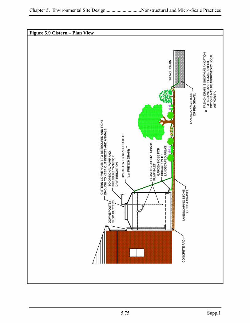
Chapter 5. Environmental Site Design.............................Nonstructural and Micro-Scale Practices
Figure 5.9 Cistern – Plan View
5.75 Supp.1

Chapter 5. Environmental Site Design............................Nonstructural and Micro-Scale Practices
Pressurization: Depending on the use of stored water, pressurization may be required. To add pressure, a pump or pressure tank can be used.
Inspection: Prior to operation, certification shall be required that the constructed system meets the conditions specified on the approved plans. Additionally, certification regarding the water tightness of the underground storage tank shall be required after its installation. Maintenance Criteria: The following items should be addressed to ensure proper maintenance and long-term performance of rainwater harvesting systems:
Privately owned practices shall have a maintenance plan and shall be protected by easement, deed restriction, ordinance, or other legal measures preventing its neglect, adverse alteration, and removal.
Access shall be provided for cleaning, inspection, and maintenance in all cisterns. A drain
plug shall also be provided to allow the system to be completely emptied if needed.
Leaf screens, gutters, and downspouts should be cleaned to prevent clogging. Built-up debris can also foster bacterial growth in gutters and downspouts.
Storage tank lids and mosquito screens should be inspected and cleaned.
Damaged components should be replaced as needed.
To avoid freezing of components, above ground systems should be disconnected, drained,
and cleaned at the start of the Winter season.
Underground system connections should be checked for frozen lines and ice blockages during Winter.
Indoor systems may require more specific maintenance.
Supp. 1 5.76

Chapter 5. Environmental Site Design.............................Nonstructural and Micro-Scale Practices
M-2. Submerged Gravel Wetlands A submerged gravel wetland is a small-scale filter using wetland plants in a rock media to provide water quality treatment. Runoff drains into the lowest elevation of the wetland, is distributed throughout the system, and discharges at the surface. Pollutant removal is achieved in a submerged gravel wetland through biological uptake from algae and bacteria growing within the filter media. Wetland plants provide additional nutrient uptake and physical and chemical treatment processes allow filtering and absorption of organic matter. Applications: A submerged gravel wetland can be located in limited spaces, typically set aside for site landscaping such as traffic islands or roadway medians. These systems are best suited for Maryland’s Eastern Shore or areas where a high water table or poorly drained soils are present. This practice is not recommended for individual lots in a residential subdivision. Depending on individual site soil characteristics, a larger drainage area may be required to maintain saturated conditions within the wetland. Performance: When designed according to the guidance provided below, PE for the contributing drainage area is based on the volume captured by submerged gravel wetlands. Constraints: The following constraints are critical when considering the use of submerged gravel wetlands to capture and treat stormwater runoff:
Space: Additional space is needed for pretreatment measures to prevent sediment or debris from entering and clogging the gravel bed.
Topography: While surrounding local slopes should be relatively flat (<2%), there needs to
be sufficient elevation drop to maintain positive drainage to and through the filter media.
Soils: The HSG should be C or D, or a high groundwater table, hard pan, or other confining layer should be present to maintain submerged flow conditions.
Drainage Area: The drainage area should be large enough (e.g., one acre) to maintain
submerged flow conditions.
Hotspot Runoff: Submerged gravel wetlands without a liner should not be used to treat hotspots that generate higher concentrations of hydrocarbons, trace metals, or toxicants than are found in typical stormwater runoff and may contaminate groundwater.
5.77 Supp.1

Chapter 5. Environmental Site Design............................Nonstructural and Micro-Scale Practices
Wetland Vegetation Establishment: Use of native wetland plant stock obtained from a local aquatic plant nursery is recommended for establishing vegetation. Design variations may use wetland mulch or topsoil on top of the gravel, which may allow for successful seed germination. However, use of the rock media for establishing wetland conditions requires specific planting stock. Frequent inspection and maintenance will be necessary until wetland plantings are well established.
Design Guidance: The following conditions should be considered when designing submerged gravel wetlands:
Conveyance: Pretreated stormwater enters via piped or overland flow and discharges into the gravel-filled chamber. A perforated pipe (4 to 6-inch preferred) at the base of the gravel layer allows for flow-through conditions and maintains a constant water surface elevation. Discharges that exceed the ESDv exit to a stable outfall at non-erosive velocities. These systems should be located off-line.
Treatment: Submerged gravel wetlands shall meet the following conditions:
o Pretreatment shall be provided for 10% of the total ESDv. An above ground forebay
area or below ground pretreatment chamber may be used. o Storage for 75% of ESDv for the entire drainage area contributing to the wetland
shall be provided. A PE value based on the ESDv captured and treated shall be applied to the contributing drainage area. Temporary ponding depth shall not be greater than the tolerance levels of the wetland vegetation. Temporary storage of ESDv may be provided above the gravel bed.
o Storage calculations shall account for the porosity of the gravel media. o The gravel substrate shall be no deeper than four feet. o Surface area requirements for stormwater wetlands in Chapter 3 do not apply to this
practice because pollutant removal primarily takes place within the rock media.
Flow Splitter: A flow splitter should be provided to divert the ESDv to the submerged gravel wetland (see Details No. 5 and No. 6, Appendix D.8).
Treatment Cells: Multiple treatment cells are optional and may be separated by earth
berms.
Observation Wells: An observation well consisting of an anchored, six-inch diameter perforated pipe shall be required. The top of the observation well shall be at least six inches above grade.
Landscaping: A minimum of three different types of wetland species shall be provided.
Replacement plantings may be necessary.
Supp. 1 5.78
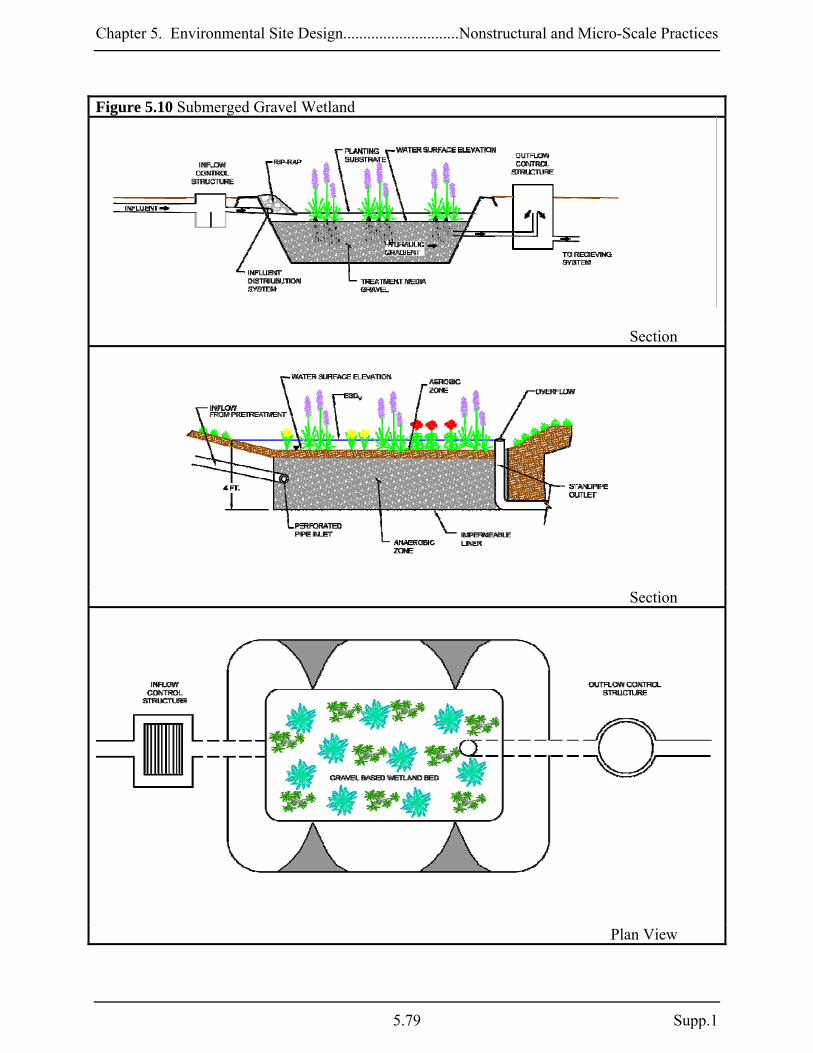
Chapter 5. Environmental Site Design.............................Nonstructural and Micro-Scale Practices
Figure 5.10 Submerged Gravel Wetland
Section
Section
Plan View
5.79 Supp.1

Chapter 5. Environmental Site Design............................Nonstructural and Micro-Scale Practices
Construction Criteria: The following items should be addressed during the construction of projects with submerged gravel wetlands:
Site Disturbance: All on-site disturbed areas should be stabilized prior to allowing runoff to enter the newly constructed wetland.
Erosion and Sediment Control: The proposed location of a submerged gravel wetland
shall be protected during construction. Surface runoff shall be diverted away from the practice during grading operations. Flow splitters and other conveyance infrastructure shall be blocked.
Wetland construction shall be performed with lightweight, wide-tracked equipment to minimize disturbance and compaction. Excavated materials shall be placed in a contained area. Any pumping operations shall discharge filtered water to a stable outlet.
Gravel Media: The aggregate shall be composed of an 18 to 48 inch layer of clean washed, uniformly graded material with a porosity of 40%. Rounded bank run gravel is recommended (e.g., ASTM D448 4,5, or 6 stone or equal)..
Inspection:
Regular inspections shall be made during the following stages of construction:
o During excavation to subgrade. o During placement of backfill of perforated inlet pipe and observation wells. o During placement of geotextiles and all filter media. o During construction of any appurtenant conveyance systems such as diversion
structures, inlets, outlets, and flow distribution structures. o Upon completion of final grading and establishment of permanent stabilization, and
before allowing runoff to enter the wetland. Maintenance Criteria: The following items should be addressed to ensure proper maintenance and long-term performance of submerged gravel wetlands:
Privately owned practices shall have a maintenance plan and shall be protected by easement, deed restriction, ordinance, or other legal measures preventing its neglect, adverse alteration, and removal.
During the first year of operation, inspections should be conducted after every major storm
and poorly established areas revegetated.
Sediment accumulation in the pretreatment areas should be removed as necessary.
Supp. 1 5.80

Chapter 5. Environmental Site Design.............................Nonstructural and Micro-Scale Practices
Signs of uneven flow distribution within the wetland may mean that the gravel or underdrain is clogged. The gravel and/or underdrain may need to be removed, cleaned, and replaced.
A dense stand of wetland vegetation should be maintained through the life of the facility with
plantings replaced as needed.
Inlets and outlets to each submerged gravel wetland cell should be free from debris to prevent clogging.
Erosion at inflow points should be repaired. Flow splitters should be functional to prevent
bypassing of the facility.
5.81 Supp.1
Chapter 5. Environmental Site Design............................Nonstructural and Micro-Scale Practices
M-3. Landscape Infiltration Landscape infiltration utilizes on-site vegetative planting areas to capture, store, and treat stormwater runoff. Rainwater is stored initially, filters through the planting soil and gravel media below, and then infiltrates into native soils. These practices can be integrated within the overall site design by utilizing a variety of landscape features for storage and treatment of stormwater runoff. Storage may be provided in constructed planters made of stone, brick, concrete, or in natural areas excavated and backfilled with stone and topsoil. Applications: Landscape infiltration can be best implemented in residential and commercial land uses. Residential areas with compact housing such as clustered homes and townhouses can utilize small green spaces for landscape infiltration. Because space in these instances prevents structural pretreatment, the drainage area to these practices should be limited to less than 10,000 ft2. Larger drainage areas may be allowed where soil testing is performed and pretreatment forebays can be implemented. Successful application is dependent upon soil type and groundwater elevation. Performance: The PE values determined by Equation 5.1 may be applied to the ESD sizing criteria when landscape infiltration systems are designed according to the guidance provided below. Rev requirements are also met when the PE from Equation 5.1 meets or exceeds the soil specific recharge factor listed in Section 2.2. Constraints: The following constraints are critical when considering the use of landscape infiltration to capture and treat stormwater runoff:
Space: Landscape infiltration should not be used in areas where operation may create a risk for basement flooding, interfere with subsurface sewage disposal systems, or other underground structures. The initial site planning process shall consider landscaping opportunities where these practices may be implemented.
Topography: Steep terrain affects the successful performance of landscape infiltration.
These practices should be constructed without a slope. If slopes entering these practices are too steep, then level-spreading devices such as check dams, terraces, or berms may be needed to maintain sheetflow.
Soils: Permeable soils are critical to the successful application of landscape infiltration.
The HSG should be A or B. For HSG C or D, designers should consider using practices with underdrains like micro-bioretention.
Supp. 1 5.82
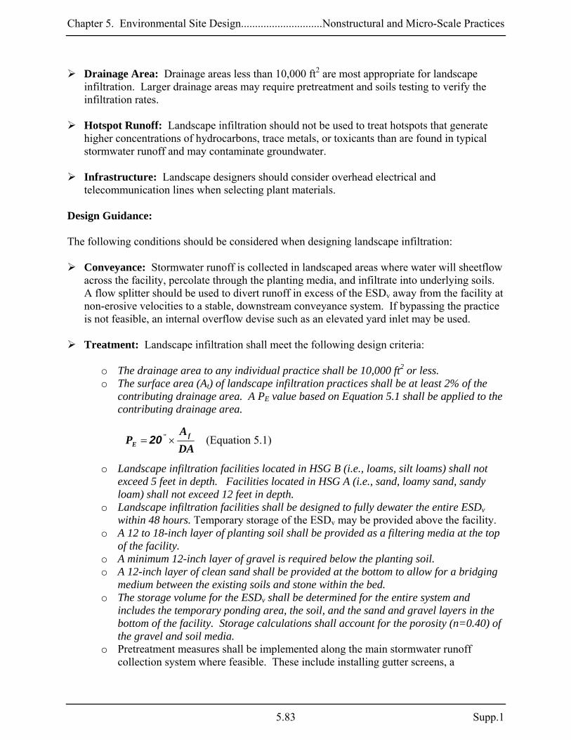
Chapter 5. Environmental Site Design.............................Nonstructural and Micro-Scale Practices
Drainage Area: Drainage areas less than 10,000 ft2 are most appropriate for landscape infiltration. Larger drainage areas may require pretreatment and soils testing to verify the infiltration rates.
Hotspot Runoff: Landscape infiltration should not be used to treat hotspots that generate
higher concentrations of hydrocarbons, trace metals, or toxicants than are found in typical stormwater runoff and may contaminate groundwater.
Infrastructure: Landscape designers should consider overhead electrical and
telecommunication lines when selecting plant materials. Design Guidance: The following conditions should be considered when designing landscape infiltration:
Conveyance: Stormwater runoff is collected in landscaped areas where water will sheetflow across the facility, percolate through the planting media, and infiltrate into underlying soils. A flow splitter should be used to divert runoff in excess of the ESDv away from the facility at non-erosive velocities to a stable, downstream conveyance system. If bypassing the practice is not feasible, an internal overflow devise such as an elevated yard inlet may be used.
Treatment: Landscape infiltration shall meet the following design criteria:
o The drainage area to any individual practice shall be 10,000 ft2 or less. o The surface area (At) of landscape infiltration practices shall be at least 2% of the
contributing drainage area. A PE value based on Equation 5.1 shall be applied to the contributing drainage area.
5.1)(EquationDAA
P fE ×= "20
o Landscape infiltration facilities located in HSG B (i.e., loams, silt loams) shall not exceed 5 feet in depth. Facilities located in HSG A (i.e., sand, loamy sand, sandy loam) shall not exceed 12 feet in depth.
o Landscape infiltration facilities shall be designed to fully dewater the entire ESDv within 48 hours. Temporary storage of the ESDv may be provided above the facility.
o A 12 to 18-inch layer of planting soil shall be provided as a filtering media at the top of the facility.
o A minimum 12-inch layer of gravel is required below the planting soil. o A 12-inch layer of clean sand shall be provided at the bottom to allow for a bridging
medium between the existing soils and stone within the bed. o The storage volume for the ESDv shall be determined for the entire system and
includes the temporary ponding area, the soil, and the sand and gravel layers in the bottom of the facility. Storage calculations shall account for the porosity (n=0.40) of the gravel and soil media.
o Pretreatment measures shall be implemented along the main stormwater runoff collection system where feasible. These include installing gutter screens, a
5.83 Supp.1

Chapter 5. Environmental Site Design............................Nonstructural and Micro-Scale Practices
removable filter screen on rooftop downspout pipes, a sand layer or pea gravel diaphragm at the inflow, or a two to three-inch surface mulch layer.
Soils: Landscape infiltration shall be installed in HSG A or B. The depth from the bottom of
the facility to the seasonal high water table, bedrock, hard pan, or other confining layer shall be greater than or equal to four feet (two feet on the lower Eastern Shore).
Flow Splitter: A flow splitter should be provided to divert excess runoff away from
landscape infiltration. An elevated yard inlet may also be used in the facility for this purpose.
Setbacks:
o Landscape infiltration shall be located down gradient of building structures and shall
be setback at least 10 feet from buildings, 50 feet from confined water supply wells, 100 feet from unconfined water supply wells, and 25 feet from septic systems.
o Landscape infiltration shall be sized and located to meet minimum local requirements for clearance from underground utilities.
Observation Wells: An observation well consisting of an anchored, perforated pipe (4” to
6” diameter) shall be provided. The top of the observation well shall be at least six inches above grade.
Landscaping: Landscaping plans shall be provided according to the guidance in Appendix
A. Plant tolerance to saturated and inundated conditions shall be considered as part of the design. A dense and diverse planting plan will provide an aesthetically pleasing design, which will enhance property value and community acceptance.
Construction Criteria: The following items should be addressed during construction of projects with landscape infiltration:
Erosion and Sediment Control: Final grading for landscape infiltration should not take place until the surrounding site is stabilized. If this cannot be accomplished, runoff from disturbed areas shall be diverted around the proposed location of the facility.
Soil Compaction: Sub soils shall not be compacted. Excavation should be conducted in dry
conditions with equipment located outside of the practice to minimize bottom and sidewall compaction. Cnstruction of the should be performed with lightweight, wide-tracked equipment to minimize disturbance and compaction. Excavated materials should be placed in a contained area.
Planter Boxes: Planter boxes may be made of stone, brick, or concrete.
Supp. 1 5.84
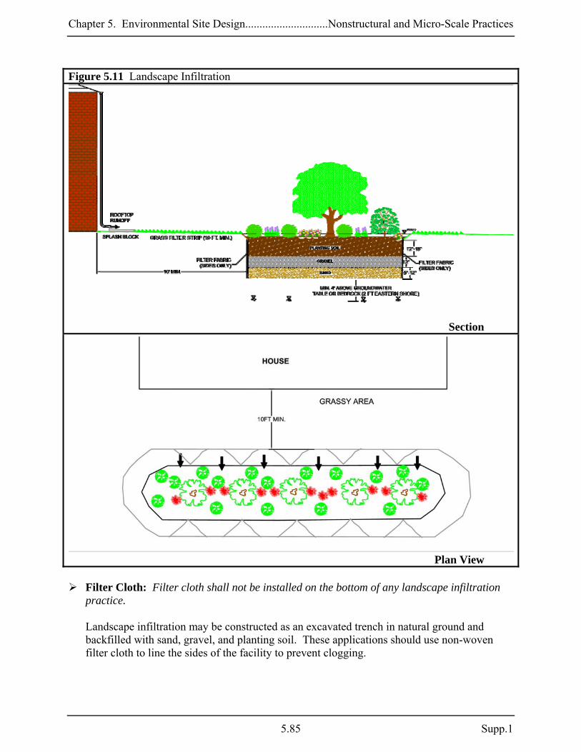
Chapter 5. Environmental Site Design.............................Nonstructural and Micro-Scale Practices
Figure 5.11 Landscape Infiltration
Section
Plan View
Filter Cloth: Filter cloth shall not be installed on the bottom of any landscape infiltration practice. Landscape infiltration may be constructed as an excavated trench in natural ground and backfilled with sand, gravel, and planting soil. These applications should use non-woven filter cloth to line the sides of the facility to prevent clogging.
5.85 Supp.1

Chapter 5. Environmental Site Design............................Nonstructural and Micro-Scale Practices
Gravel and Filter Media: See Appendix B.4 for material specifications for the sand, gravel, and planting soil media.
Landscape Installation: The optimum planting time is during the autumn months. Spring
is also acceptable but may require watering. Inspection:
Regular inspections shall be made during the following stages of construction:
o During excavation to subgrade. o During placement of backfill and observation well. o During placement of filter fabric, soil, and gravel media. o During construction of appurtenant conveyance structures. o Upon completion of final grading and establishment of permanent stabilization.
Maintenance Criteria: The following items should be addressed to ensure proper maintenance and long-term performance of landscape infiltration:
Privately owned practices shall have a maintenance plan and shall be protected by easement, deed restriction, ordinance, or other legal measures preventing its neglect, adverse alteration, and removal.
During the first year of operation, inspection frequency should be after every major storm
and poorly established areas revegetated.
Sediment accumulation on the surface of the facility should be removed and the top two to three inches of surface layer replaced as needed.
The top few inches of the planting soil should be removed and replaced when water ponds
for more than 48 hours or there is algal growth on the surface of the facility.
If standing water persists after filter media has been maintained, the gravel, soil, and sand may need to be cleaned and/or replaced.
Occasional pruning and replacement of dead vegetation is necessary. If specific plants are
not surviving, more appropriate species should be used. Watering may be required during prolonged dry periods.
Supp. 1 5.86

Chapter 5. Environmental Site Design.............................Nonstructural and Micro-Scale Practices
M-4. Infiltration Berms An infiltration berm is a mound of earth composed of soil and stone that is placed along the contour of a relatively gentle slope. This practice may be constructed by excavating upslope material to create a depression and storage area above a berm or earth dike. Stormwater runoff flowing downslope to the depressed area filters through the berm in order to maintain sheetflow. Infiltration berms should be used in conjunction with practices that require sheetflow (e.g., sheetflow to buffers) or in a series on steeper slopes to prevent flow concentration. Applications: Infiltration berms may be used on gently sloping areas in residential, commercial, open space, or wooded land use conditions. They must be installed along the contour in order to perform effectively. The purpose of this practice is to augment natural stormwater drainage functions in the landscape by promoting sheetflow and dissipating runoff velocities. Performance: Infiltration berms may be incorporated into the design with other practices such as disconnection of rooftop and non-rooftop runoff, sheetflow to conservation areas, or grass swales to enhance pollutant removal. Constraints: The following constraints are critical when considering the use of infiltration berms to treat stormwater runoff:
Space: The presence of large trees may limit the use of infiltration berms along a hillside. Berms may be threaded carefully along the contour of wooded slopes in order to avoid disturbing existing vegetation.
Topography: Infiltration berms should not be installed on slopes greater than 10% to
prevent erosion at the upstream toe of the berm.
Soils: Infiltration berms should not be installed on slopes where soils have low shear strength (or identified as “slough prone” or “landslide prone”).
Drainage Area: The drainage area should be small enough to prevent flow concentration
upslope of the berm.
Hotspot Runoff: When infiltration berms are designed in conjunction with other infiltration practices, they should not be used to treat hotspots that generate higher concentrations of hydrocarbons, trace metals, or toxicants than found in typical stormwater runoff and may contaminate groundwater.
5.87 Supp.1
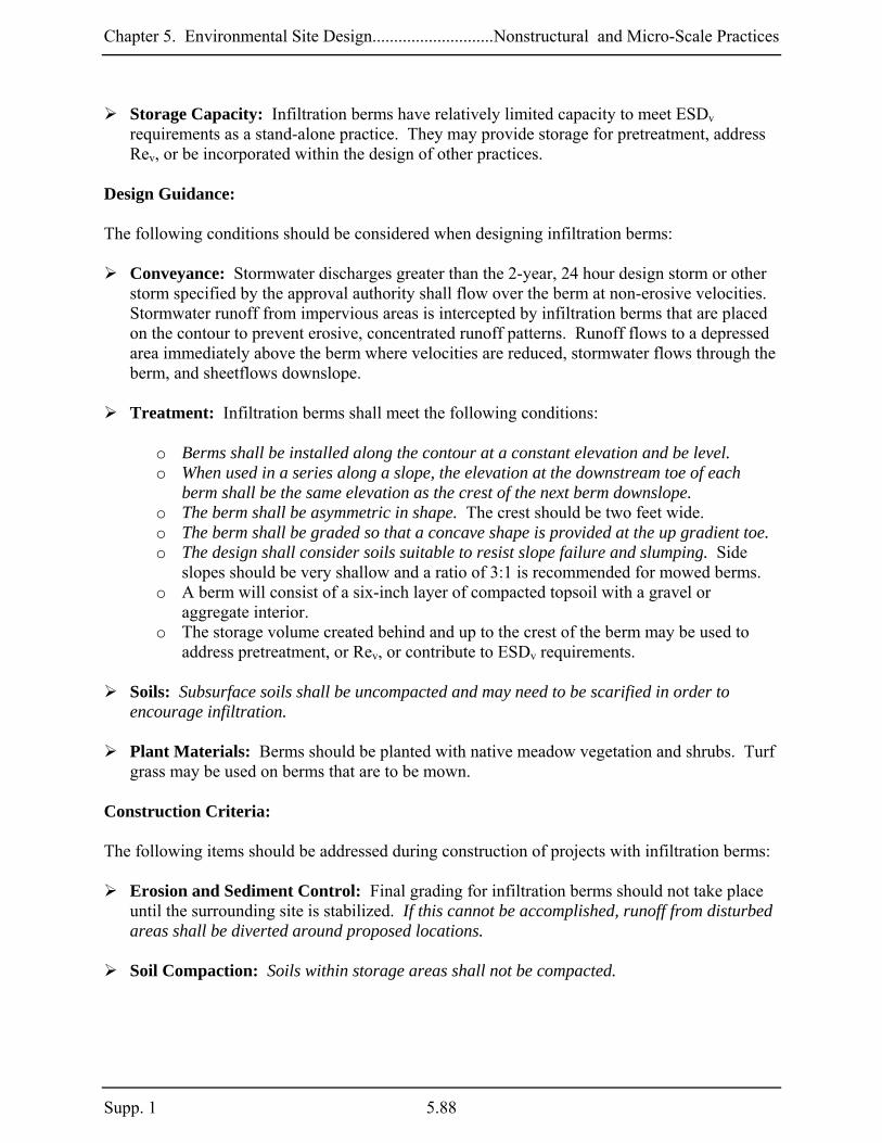
Chapter 5. Environmental Site Design............................Nonstructural and Micro-Scale Practices
Storage Capacity: Infiltration berms have relatively limited capacity to meet ESDv requirements as a stand-alone practice. They may provide storage for pretreatment, address Rev, or be incorporated within the design of other practices.
Design Guidance: The following conditions should be considered when designing infiltration berms:
Conveyance: Stormwater discharges greater than the 2-year, 24 hour design storm or other storm specified by the approval authority shall flow over the berm at non-erosive velocities. Stormwater runoff from impervious areas is intercepted by infiltration berms that are placed on the contour to prevent erosive, concentrated runoff patterns. Runoff flows to a depressed area immediately above the berm where velocities are reduced, stormwater flows through the berm, and sheetflows downslope.
Treatment: Infiltration berms shall meet the following conditions:
o Berms shall be installed along the contour at a constant elevation and be level. o When used in a series along a slope, the elevation at the downstream toe of each
berm shall be the same elevation as the crest of the next berm downslope. o The berm shall be asymmetric in shape. The crest should be two feet wide. o The berm shall be graded so that a concave shape is provided at the up gradient toe. o The design shall consider soils suitable to resist slope failure and slumping. Side
slopes should be very shallow and a ratio of 3:1 is recommended for mowed berms. o A berm will consist of a six-inch layer of compacted topsoil with a gravel or
aggregate interior. o The storage volume created behind and up to the crest of the berm may be used to
address pretreatment, or Rev, or contribute to ESDv requirements.
Soils: Subsurface soils shall be uncompacted and may need to be scarified in order to encourage infiltration.
Plant Materials: Berms should be planted with native meadow vegetation and shrubs. Turf
grass may be used on berms that are to be mown. Construction Criteria: The following items should be addressed during construction of projects with infiltration berms:
Erosion and Sediment Control: Final grading for infiltration berms should not take place until the surrounding site is stabilized. If this cannot be accomplished, runoff from disturbed areas shall be diverted around proposed locations.
Soil Compaction: Soils within storage areas shall not be compacted.
Supp. 1 5.88
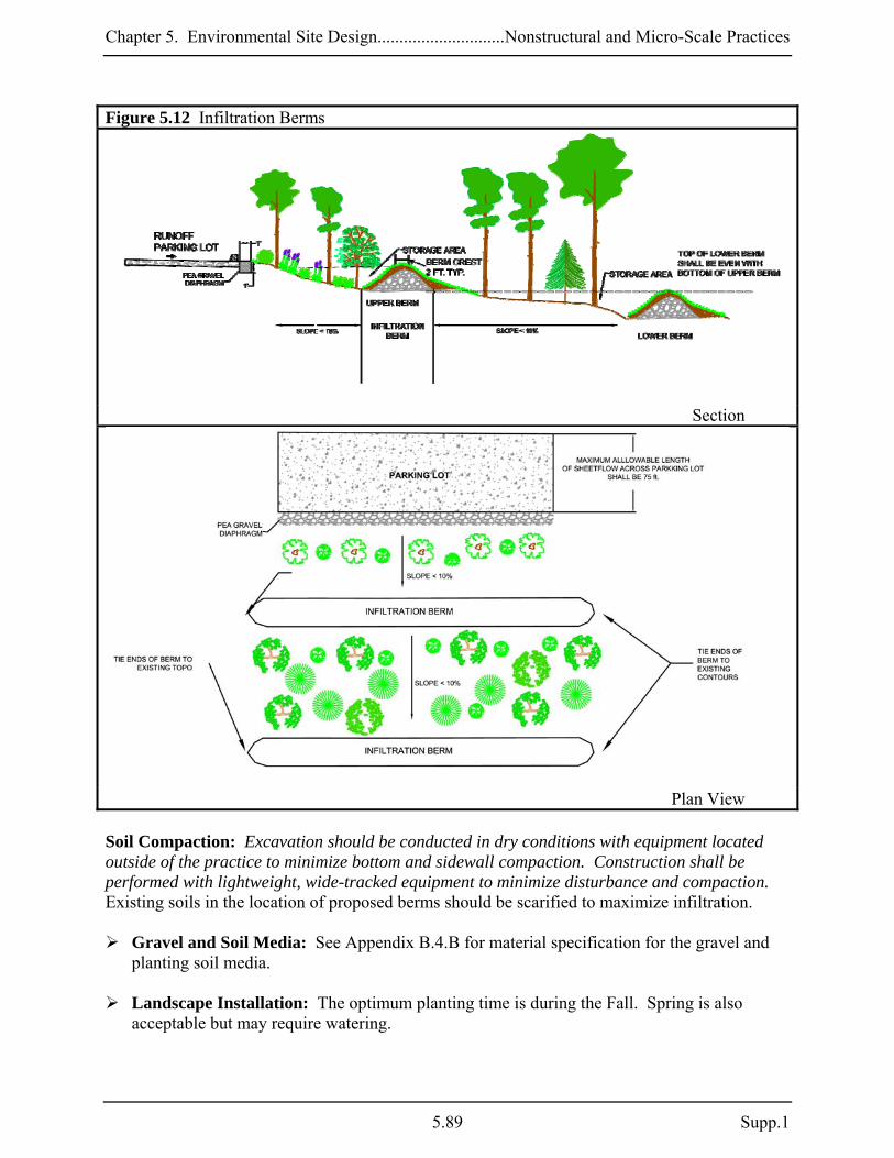
Chapter 5. Environmental Site Design.............................Nonstructural and Micro-Scale Practices
Figure 5.12 Infiltration Berms
Section
Plan View
Soil Compaction: Excavation should be conducted in dry conditions with equipment located outside of the practice to minimize bottom and sidewall compaction. Construction shall be performed with lightweight, wide-tracked equipment to minimize disturbance and compaction. Existing soils in the location of proposed berms should be scarified to maximize infiltration.
Gravel and Soil Media: See Appendix B.4.B for material specification for the gravel and planting soil media.
Landscape Installation: The optimum planting time is during the Fall. Spring is also
acceptable but may require watering.
5.89 Supp.1

Chapter 5. Environmental Site Design............................Nonstructural and Micro-Scale Practices
Implementation with Other Practices: When infiltration berms are incorporated into a system using other practices (e.g., Disconnection of Non-Rooftop Runoff), the Construction Criteria for that practice shall also be considered.
Inspection:
Regular inspections shall be made during the following stages of construction:
o During placement of gravel media, and soil. o Upon completion of final grading and establishment of permanent stabilization.
Maintenance Criteria: The following items should be addressed to ensure proper maintenance and long-term performance of infiltration berms:
Berms should be inspected regularly to ensure that ponding water does not create nuisance conditions.
Signs of concentrated flow and other surface erosion should be repaired to promote
sheetflow.
A dense mat of vegetation should be present at all times. Vegetation should be replaced as needed.
When infiltration berms are incorporated in a system using other practices, the Maintenance
Criteria for that practice shall also be considered.
Supp. 1 5.90

Chapter 5. Environmental Site Design.............................Nonstructural and Micro-Scale Practices
M-5. Dry Wells A dry well is an excavated pit or structural chamber filled with gravel or stone that provides temporary storage of stormwater runoff from rooftops. The storage area may be constructed as a shallow trench or a deep well. Rooftop runoff is directed to these storage areas and infiltrates into the surrounding soils prior to the next storm event. The pollutant removal capability of dry wells is directly proportional to the amount of runoff that is stored and allowed to infiltrate. Applications: Dry wells can be used in both residential and commercial sites and are best suited for treating runoff from small drainage areas such as a single rooftop or downspout. Dry wells are not appropriate for treating runoff from large impervious areas such as a parking lot. Successful application is dependent upon soil type and groundwater elevation. Performance: When designed according to the guidance provided below, dry wells will provide treatment for the required ESDv and Rev. Constraints: The following constraints are critical when considering the use of dry wells to capture and infiltrate stormwater runoff:
Space: Dry wells should not be used in areas where their operation may create a risk for basement flooding, interfere with subsurface sewage disposal systems, or affect other underground structures. There are limited opportunities for dry well implementation in high-density neighborhoods.
Topography: Steep terrain affects the successful performance of a dry well. Installation on
slopes greater than 20% should be avoided.
Soils: Permeable soils are critical to the successful application of dry wells. The HSG should be A or B. For HSG C or D or compacted soils, designers should consider using practices with underdrains like micro-bioretention.
Drainage Area: Small drainage areas (e.g., 500 ft2) are most appropriate for dry well
applications. Larger non-residential areas may be treated provided the dry well is sized according to the requirements for infiltration practices found in Section 3.3.
Hotspot Runoff: Dry wells should not be used to treat hotspots that generate higher
concentrations of hydrocarbons, trace metals, or toxicants than are found in typical stormwater runoff and may contaminate groundwater.
5.91 Supp.1

Chapter 5. Environmental Site Design............................Nonstructural and Micro-Scale Practices
Operation: Dry wells are subject to neglect by homeowners. Education is needed to ensure that proper maintenance will allow the system to continue to function properly.
Design Guidance: The following conditions should be considered when designing dry wells:
Conveyance: Discharge from the overflow shall be directed to an above ground splash pad and conveyed in a non-erosive manner to a stable outfall. Rooftop runoff is collected through gutters and downspouts and discharged directly into a dry well. The downspout extends underground and across the entire length of a dry well. An overflow pipe is also installed to pass excess runoff generated from larger storms.
Treatment: Dry wells shall meet the following conditions:
o Pretreatment measures shall be installed to allow filtering of sediment, leaves, or
other debris. This may be done by providing gutter screens and a removable filter screen installed within the downspout pipe or other locally-approved method. The removable filter screen should be installed below the overflow outlet and easily removed so that homeowners can clean the filter.
o A dry well shall be designed to capture and store the ESDv. A PE value based on the ESDv captured and treated shall be applied to the contributing drainage area. The storage area for the ESDv includes the sand and gravel layers in the bottom of the facility. Storage calculations shall account for the porosity of the gravel and sand media.
o The drainage area to each dry well shall not exceed 1,000 square feet. Drainage areas should be small enough to allow infiltration into the ground within 48 hours (e.g., 500 ft2 to each downspout). Infiltration trenches may be used to treat runoff from larger drainage areas (see Section 3.3).
o Dry wells located in HSG B (i.e., loams, silt loams) shall not exceed 5 feet in depth. Dry wells located in HSG A (i.e., sand, loamy sand, sandy loam) shall not exceed 12 feet in depth.
o The length of a dry well should be longer than the width to ensure proper water distribution and maximize infiltration.
o A one-foot layer of clean sand shall be provided in the bottom of a dry well to allow for bridging between the existing soils and trench gravel.
Soils: Dry wells shall be installed in HSG A or B. The depth from the bottom of a dry well to
the seasonal high water table, bedrock, hard pan, or other confining layer shall be greater than or equal to four feet (two feet on the lower Eastern Shore).
Supp. 1 5.92

Chapter 5. Environmental Site Design.............................Nonstructural and Micro-Scale Practices
Figure 5.13 Dry Well
Section
Gutter Drain Filter (Typical)
5.93 Supp.1

Chapter 5. Environmental Site Design............................Nonstructural and Micro-Scale Practices
Setbacks:
o Dry wells shall be located down gradient of building structures and shall be setback at least 10 feet from buildings, 50 feet from confined water supply wells, 100 feet from unconfined water supply wells, and 25 feet from septic systems.
o Dry wells shall be setback a minimum of 100 feet from fill slopes of 15% and 200 feet from fill slopes of 25%.
Observation Wells: An observation well consisting of an anchored, 4 to 6-inch diameter
perforated pipe shall be required. The top of the observation well shall be at least six inches above grade.
Underground Distribution Pipe: This pipe (4 to 6 inch diameter) will be perforated to fill
the trench along its entire length.
Landscaping: A minimum one-foot of soil cover shall be provided from the top of the trench to the ground surface elevation. The soil should be stabilized with a dense cover of vegetation. In areas where frost heave is a concern, soil cover may need to be as much as four feet. In these cases, a geotechnical engineer should be consulted.
Construction Criteria: The following items should be addressed during construction of projects with dry wells:
Erosion and Sediment Control: Final grading for proposed dry wells should not take place until the surrounding site is completely stabilized. If this cannot be accomplished, runoff from disturbed areas shall be diverted.
Soil Compaction: Excavation should be conducted in dry conditions with equipment located
outside of the practice to minimize bottom and sidewall compaction. Construction of a dry well shall be performed with lightweight, wide-tracked equipment to minimize disturbance and compaction. Excavated materials shall be placed in a contained area.
Underground Chamber: A subsurface prefabricated chamber may be used.
Dry Well Bottom: The bottom shall be as level as possible to minimize pooled water in
small areas that may reduce overall infiltration and longevity.
Filter Cloth: Filter cloth shall not be installed on the bottom of the well. Non-woven filter cloth should be used to line the top and sides of the dry well to prevent the pore space between the stones from being blocked by the surrounding native material.
Gravel Media: The aggregate shall be composed of an 18 to 48-inch layer of clean washed,
open graded material with 40% porosity (e.g., ASTM D448 4,5, or 6 stone or equal).
Supp. 1 5.94

Chapter 5. Environmental Site Design.............................Nonstructural and Micro-Scale Practices
Inspection:
Regular inspections shall be made during the following stages of construction:
o During excavation to subgrade. o During placement of backfill and perforated inlet pipe and observation well. o During placement of geotextiles and all filter media. o During construction of the appurtenant conveyance. o Upon completion of final grading and establishment of permanent stabilization.
Maintenance Criteria: The following items should be addressed to ensure proper maintenance and long-term performance of dry wells:
Privately owned practices shall have a maintenance plan and shall be protected by easement, deed restriction, ordinance, or other legal measures preventing its neglect, adverse alteration, and removal.
Dry wells shall be inspected and cleaned annually. This includes pipes, gutters, downspouts,
and all filters.
Ponding, standing water, or algal growth on the top of a dry well may indicate failure due to sedimentation in the gravel media. If water ponds for more than 48 hours after a major storm or more than six inches of sediment has accumulated, the gravel media should be excavated and replaced.
5.95 Supp.1
Chapter 5. Environmental Site Design............................Nonstructural and Micro-Scale Practices
M-6. Micro-Bioretention Micro-bioretention practices capture and treat runoff from discrete impervious areas by passing it through a filter bed mixture of sand, soil, and organic matter. Filtered stormwater is either returned to the conveyance system or partially infiltrated into the soil. Micro-bioretention practices are versatile and may be adapted for use anywhere there is landscaping. Applications: Micro-bioretention is a multi-functional practice that can be easily adapted for new and redevelopment applications in commercial and industrial projects. Stormwater runoff is stored temporarily and filtered in landscaped facilities shaped to take runoff from various sized impervious areas. Micro-bioretention provides water quality treatment, aesthetic value, and can be applied as concave parking lot islands, linear roadway or median filters, terraced slope facilities, residential cul-de-sac islands, and ultra-urban planter boxes. Performance: The PE values determined by Equation 5.2 may be applied to the ESD sizing criteria when micro-bioretention systems are designed according to the guidance provided below. Rev requirements are also met when the PE from Equation 5.2 meets or exceeds the soil specific recharge factor listed in Section 2.2. Constraints: The following constraints are critical when considering the use of micro-bioretention to capture and treat stormwater runoff:
Space: The surface area of a typical micro-bioretention filter is dependent on the area of the contributing imperviousness. The size and distribution of open areas within a project (e.g., parking lot islands, landscaped areas) must be considered early during a project’s planning and design if these practices are considered.
Topography: Slopes of contributing areas and filter beds should be gradual (< 5%). If
slopes are too steep, then level-spreading devices may be needed to redistribute flow prior to filtering. If slopes within micro-bioretention practice are too steep, then a series of check dams, terraces, or berms may be needed to maintain sheetflow internally.
There should also be an elevation difference between the inflow and outflow of a micro-bioretention practice to allow flow through the filter. This difference is critical when designing downstream conveyance systems (e.g., grass channels, storm drains).
Soils: Soil conditions are a crucial determining factor for micro-bioretention because
specific applications will be affected. When located in sandier soils, these practices may be used to promote recharge (see M-3, Landscape Infiltration). If clayey soils are encountered,
Supp. 1 5.96

Chapter 5. Environmental Site Design.............................Nonstructural and Micro-Scale Practices
an underdrain system may be needed to convey water downstream. Also, elevated groundwater may limit filter bed thickness and excavated applications.
Subsurface water conditions (e.g., water table) will help determine the thickness of filter beds used. The probability of practice failure increases if the filter bed intercepts groundwater. Therefore, micro-bioretention practice inverts should be above local groundwater tables.
Drainage Area: The drainage area to micro-bioretention practices should be limited. As the impervious area draining to each practice exceeds ½ acre, practice effectiveness weakens and larger systems designed according to Chapter 3 should be considered.
Hotspot Runoff: Micro-bioretention practices that are designed to promote infiltration of
runoff into the ground should not be used to treat hotspots that generate higher concentrations of hydrocarbons, trace metals, or toxicants than are typically found in stormwater runoff and may contaminate groundwater.
Infrastructure: The location of existing and proposed buildings and utilities (e.g., water
supply wells, sewer, storm drains, electricity) will influence the design and construction of micro-bioretention. Landscape designers should also consider overhead electrical and telecommunication lines when selecting trees to be planted.
Design Guidance: The following conditions should be considered when designing micro-bioretention practices:
Conveyance: Micro-bioretention systems should be designed off-line whenever possible. A flow splitter should be used to divert excess runoff away from the filter media to a stable, downstream conveyance system. If bypassing a micro-bioretention practice is impractical, an internal overflow device (e.g., elevated yard inlet) may be used.
Runoff shall enter, flow through, and exit micro-bioretention practices in a safe and non-erosive manner. Inflow may be through depressed curbs with wheel stops, curb cuts, or conveyed directly using downspouts, covered drains, or catch basins. Depending on site layout and the size and shape of the impervious area being treated, overflow structures should be located to maximize internal flow paths through the filter media. An underdrain system may be necessary to discharge treated stormwater safely downstream. Underdrains may be interconnected to other micro-scale practices as part of a treatment system or directly to the storm drain.
5.97 Supp.1
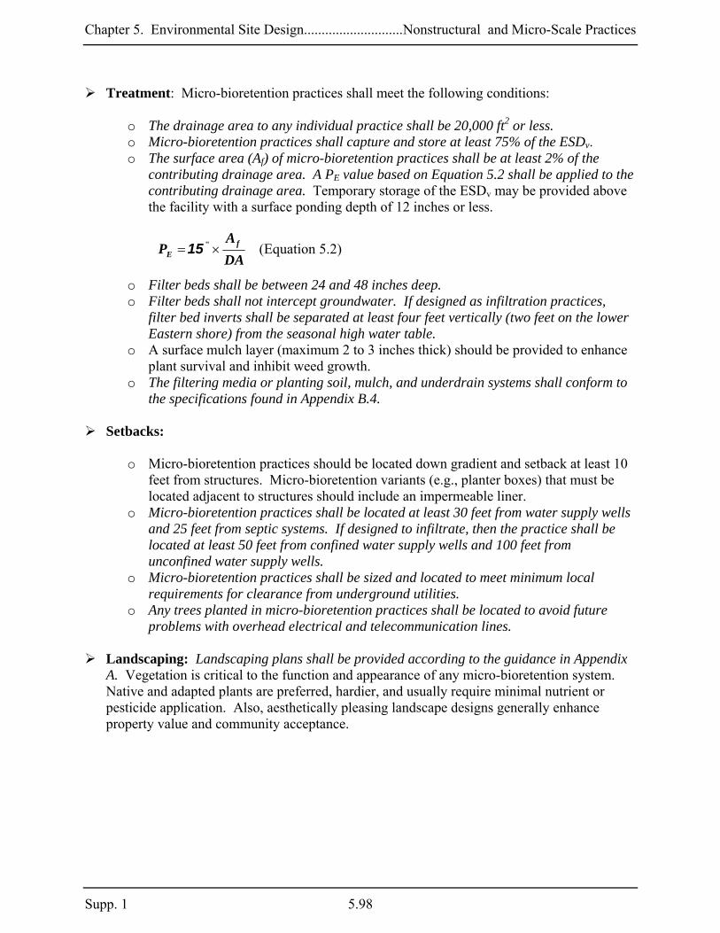
Chapter 5. Environmental Site Design............................Nonstructural and Micro-Scale Practices
Treatment: Micro-bioretention practices shall meet the following conditions:
o The drainage area to any individual practice shall be 20,000 ft2 or less. o Micro-bioretention practices shall capture and store at least 75% of the ESDv. o The surface area (Af) of micro-bioretention practices shall be at least 2% of the
contributing drainage area. A PE value based on Equation 5.2 shall be applied to the contributing drainage area. Temporary storage of the ESDv may be provided above the facility with a surface ponding depth of 12 inches or less.
5.2)(EquationDAA
P fE ×= "15
o Filter beds shall be between 24 and 48 inches deep. o Filter beds shall not intercept groundwater. If designed as infiltration practices,
filter bed inverts shall be separated at least four feet vertically (two feet on the lower Eastern shore) from the seasonal high water table.
o A surface mulch layer (maximum 2 to 3 inches thick) should be provided to enhance plant survival and inhibit weed growth.
o The filtering media or planting soil, mulch, and underdrain systems shall conform to the specifications found in Appendix B.4.
Setbacks:
o Micro-bioretention practices should be located down gradient and setback at least 10
feet from structures. Micro-bioretention variants (e.g., planter boxes) that must be located adjacent to structures should include an impermeable liner.
o Micro-bioretention practices shall be located at least 30 feet from water supply wells and 25 feet from septic systems. If designed to infiltrate, then the practice shall be located at least 50 feet from confined water supply wells and 100 feet from unconfined water supply wells.
o Micro-bioretention practices shall be sized and located to meet minimum local requirements for clearance from underground utilities.
o Any trees planted in micro-bioretention practices shall be located to avoid future problems with overhead electrical and telecommunication lines.
Landscaping: Landscaping plans shall be provided according to the guidance in Appendix
A. Vegetation is critical to the function and appearance of any micro-bioretention system. Native and adapted plants are preferred, hardier, and usually require minimal nutrient or pesticide application. Also, aesthetically pleasing landscape designs generally enhance property value and community acceptance.
Supp. 1 5.98
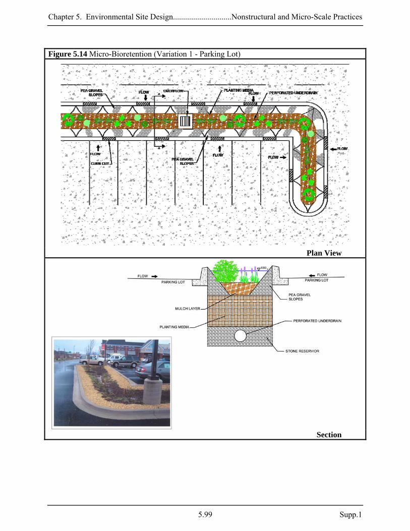
Chapter 5. Environmental Site Design.............................Nonstructural and Micro-Scale Practices
Figure 5.14 Micro-Bioretention (Variation 1 - Parking Lot)
Plan View
Section
5.99 Supp.1

Chapter 5. Environmental Site Design............................Nonstructural and Micro-Scale Practices
Figure 5.15 Micro-Bioretention (Variation 2 - Parking Lot)
Plan View
Section
Supp. 1 5.100

Chapter 5. Environmental Site Design.............................Nonstructural and Micro-Scale Practices
Figure 5.16 Micro-Bioretention (Variation 3)
Profile
Plan View
Construction Criteria: The following items should be addressed during construction of projects with micro-bioretention:
Erosion and Sediment Control: Micro-bioretention practices should not be constructed until the contributing drainage area is stabilized. If this is impractical, runoff from disturbed
5.101 Supp.1

Chapter 5. Environmental Site Design............................Nonstructural and Micro-Scale Practices
areas shall be diverted away and no sediment control practices shall be used near the proposed location.
Soil Compaction: Excavation should be conducted in dry conditions with equipment
located outside of the practice to minimize bottom and sidewall compaction. Only lightweight, low ground-contact equipment should be used within micro-bioretention practices and the bottom scarified before installing underdrains and filtering media.
Underdrain Installation: Gravel for the underdrain system should be clean, washed, and
free of fines. Underdrain pipes should be checked to ensure that both the material and perforations meet specifications. The upstream ends of the underdrain pipe should be capped prior to installation.
Filter Media Installation: Bioretention soils may be mixed on-site before placement.
However, soils should not be placed under saturated conditions. The filter media should be placed and graded using excavators or backhoes operating adjacent to the practice and be placed in horizontal layers (12 inches per lift maximum). Proper compaction of the media will occur naturally. Spraying or sprinkling water on each lift until saturated may quicken settling times.
Landscape Installation: The optimum planting time is during the Fall. Spring planting is
also acceptable but may require watering. Inspection:
Regular inspections shall be made during the following stages of construction:
o During excavation to subgrade and placement and backfill of underdrain systems. o During placement of filter media. o During construction of appurtenant conveyance. o Upon completion of final grading and establishment of permanent stabilization.
Maintenance Criteria: The following items should be addressed to ensure proper maintenance and long-term performance of micro-bioretention practices:
Privately owned practices shall have a maintenance plan and shall be protected by easement, deed restriction, ordinance, or other legal measures preventing its neglect, adverse alteration, and removal.
The top few inches of filter media should be removed and replaced when water ponds for
more than 48 hours. Silts and sediment should be removed from the surface of the filter bed when accumulation exceeds one inch.
Supp. 1 5.102

Chapter 5. Environmental Site Design.............................Nonstructural and Micro-Scale Practices
Where practices are used to treat areas with higher concentrations of heavy metals (e.g., parking lots, roads), mulch should be replaced annually. Otherwise, the top two to three inches should be replaced as necessary.
Occasional pruning and replacement of dead vegetation is necessary. If specific plants are
not surviving, more appropriate species should be used. Watering may be required during prolonged dry periods.
5.103 Supp.1

Chapter 5. Environmental Site Design............................Nonstructural and Micro-Scale Practices
M-7. Rain Gardens A rain garden is a shallow, excavated landscape feature or a saucer-shaped depression that temporarily holds runoff for a short period of time. Rain gardens typically consist of an absorbent-planted soil bed, a mulch layer, and planting materials such as shrubs, grasses, and flowers. An overflow conveyance system is included to pass larger storms. Captured runoff from downspouts, roof drains, pipes, swales, or curb openings temporarily ponds and slowly filters into the soil over 24 to 48 hours. Applications: Rain gardens can be primary or secondary practices on residential, commercial, industrial, or institutional sites. This practice is typically used to treat runoff from small impervious areas like rooftops, driveways, and sidewalks. Rain gardens can also be used in retrofitting and redevelopment applications and in series where existing slopes require energy dissipation. Performance: The PE values determined by Equation 5.3 may be applied to the ESD sizing criteria when rain gardens are designed according to the guidance provided below. Rev requirements are also met when the PE from Equation 5.3 meets or exceeds the soil specific recharge factor listed in Section 2.2. Constraints: The following constraints are critical when considering the use of rain gardens to capture and treat stormwater runoff:
Topography: Rain gardens require relatively flat slopes (< 5%) to accommodate runoff filtering through the system. Some design modifications can address this constraint through the use of infiltration berms, terracing, and timber or block retaining walls on moderate slopes.
Soils: Clayey soils or soils that have been compacted by construction equipment greatly
reduce the effectiveness of this practice. Loosening of compacted soils may improve drainage capability.
Drainage Area: The drainage area to a rain garden should be relatively small, typically less
than 2,000 square feet.
Infrastructure: The location of existing and proposed buildings and utilities (e.g., water supply wells, sewer, storm drains, electricity) will influence rain garden design and construction. Landscape designers should also consider overhead electrical and telecommunication lines when selecting trees to be planted.
Supp. 1 5.104

Chapter 5. Environmental Site Design.............................Nonstructural and Micro-Scale Practices
Location:
o Lot-by-lot use of rain gardens is not recommended in residential subdivisions due to removal by homeowners. If used on a lot-by-lot basis, educating the homeowners will be needed to prevent removal.
o Rain garden excavation in areas with heavy tree cover may damage adjacent tree root systems.
Design Guidance: The following conditions should be considered when designing rain gardens:
Conveyance: Runoff shall enter, flow through, and exit rain gardens in a safe and non-erosive manner. Energy dissipation shall be provided for downspout discharges using a plunge area, rocks, splash blocks, stone dams, etc. Runoff shall enter a rain garden at the surface through grass swales and/or a gravel bed. A minimum internal slope of one percent should be maintained and a shallow berm surrounding the rain garden is recommended to avoid short-circuiting. For sloped applications, a series of rain gardens can be used as “scalloped” terraces to convey water non-erosively.
Treatment: Rain gardens shall meet the following conditions:
o The drainage area to a rain garden serving a single lot in a residential subdivision
shall be 2,000 ft² or less. The maximum drainage area to a rain garden for all other applications shall be 10,000 ft2. Micro-bioretention (M-6) or bioretention (F-6) should be considered when these requirements are exceeded.
o The surface area (Af) of rain gardens shall be at least 2% of the contributing drainage area. A PE value based on Equation 5.3 shall be applied to the contributing drainage area. Temporary storage of the ESDv may be provided above the facility with a surface ponding depth of 6 inches or less.
5.3)(EquationDAA
P fE ×= "10
o Excavated rain gardens work best where HSG A and B are prevalent. In areas of HSG C and D, at-grade applications or soil amendments should be considered.
o A minimum six to twelve-inch layer of planting soil shall be provided. o A mulch layer two to three inches deep shall be applied to the planting soil to
maintain soil moisture and to prevent premature clogging. o The planting soil and mulch shall conform to the specifications found in Appendix
B.4.
Landscaping: Landscaping plans shall clearly specify how vegetation will be established and managed. A rain garden should be located in full to partial sun, at least two feet above the seasonal high water table and be 12 to 18 inches deep. Plants selected for use in a rain garden should tolerate both saturated and dry conditions and be native or adapted to
5.105 Supp.1

Chapter 5. Environmental Site Design............................Nonstructural and Micro-Scale Practices
Maryland. Neatly trimmed shrubs, a crisp lawn edge, stone retaining walls, and other devices can be used to keep a rain garden neat and visually appealing.
Construction Criteria: The following items should be addressed during the construction of projects with rain gardens:
Erosion and Sediment Control: Rain gardens shall not be constructed until the contributing drainage area is stabilized. During construction, runoff should be diverted and the use of heavy equipment avoided to minimize compaction.
Planting Soil: Planting soil should be mixed on-site prior to installation. If poor soils are
encountered beneath the rain garden, a four-inch layer of washed gravel (⅛ to ⅜ inch gravel preferred) may be used below the planting soil mix.
Landscape Installation: The optimum planting time is during the Fall. Spring planting is
also acceptable but may require watering. Inspection:
Regular inspections shall be made during the following stages of construction:
o During excavation to subgrade and placement of planting soil. o Upon completion of final grading and establishment of permanent stabilization.
Maintenance Criteria: The following items should be addressed to ensure proper maintenance and long-term performance of rain gardens:
Privately owned practices shall have a maintenance plan and be protected by easement, deed restriction, ordinance, or other legal measures preventing its neglect, adverse alteration, and removal.
Rain garden maintenance is generally no different than that required of other landscaped
areas.
The top few inches of the planting soil should be removed and replaced when water ponds for more than 48 hours. Silts and sediment should be removed from the surface of the bed as needed.
Where practices are used to treat areas with higher concentrations of heavy metals (e.g.,
parking lots, roads), mulch should be replaced annually. Otherwise, the top two to three inches should be replaced as necessary.
Occasional pruning and replacement of dead vegetation is necessary. If specific plants are
not surviving, more appropriate species should be used. Watering may be required during prolonged dry periods.
Supp. 1 5.106

Chapter 5. Environmental Site Design.............................Nonstructural and Micro-Scale Practices
Figure 5.17 Rain Garden
Section
Plan View
Section
5.107 Supp.1
Chapter 5. Environmental Site Design............................Nonstructural and Micro-Scale Practices
M-8. Swales Swales are channels that provide conveyance, water quality treatment, and flow attenuation of stormwater runoff. Swales provide pollutant removal through vegetative filtering, sedimentation, biological uptake, and infiltration into the underlying soil media. Three design variants covered in this section include grass swales, wet swales, and bio-swales. Implementation of each is dependent upon site soils, topography, and drainage characteristics. Applications: Swales can be used for primary or secondary treatment on residential, commercial, industrial, or institutional sites. Swales can also be used for retrofitting and redevelopment. The linear structure allows use in place of curb and gutter along highways, residential roadways, and along property boundaries. Wet swales are ideal for treating highway runoff in low-lying or flat terrain with high groundwater. Bio-swales can be used in all soil types due to the use of an underdrain. Grass swales are best suited along highway and roadway projects. Performance: The PE values determined by the equations 5.2 and 5.3 (reprinted below) may be applied to the ESD sizing criteria when grass swales and bio-swales are designed according to the guidance provided below. For wet swales, PE for the contributing drainage area is based on the volume captured. Rev requirements are also met when the applicable PE meets or exceeds the soil specific recharge factor listed in Section 2.2. Swales should not be designed to meet Qp or Qf requirements except under extremely unusual conditions. Swales may be used to convey runoff for these larger storm events however, the ESDv should be treated separately. This can be accomplished with a flow splitter or diversion so that the entire design storm is passed safely. Constraints: The following constraints are critical when considering the use of swales to capture and treat stormwater runoff:
Topography: Steep slopes will increase velocity, erosion, and sediment deposition thus shortening the design life of the swale.
Soils: Design variants are dependent upon soil types. Grass swales work best in HSG A, B,
or C and wet swales are best suited for HSG C or D. Bio-swales typically include an underdrain and may be installed in all soil types. Extreme temperatures and frozen ground need to be considered when calculating design volumes.
Drainage Area: The drainage area contributing to all design variants should be less than
one acre. Practices in Chapter 3 should be considered for larger drainage areas.
Supp. 1 5.108

Chapter 5. Environmental Site Design.............................Nonstructural and Micro-Scale Practices
5.109 Supp.1
Hotspot Runoff: Swales should not be used to treat hotspots that generate higher concentrations of hydrocarbons, trace metals, or toxicants than are found in typical stormwater runoff and may contaminate groundwater.
Location: The location of swales needs to be considered carefully. Wet swales are not
recommended for residential developments due to the potential nuisance or mosquito breeding conditions. Swales along roadways can be damaged by off-street parking and are susceptible to winter salt applications. Also, the choice of vegetation and landscaping can be limited in adjacent areas.
Design Guidance: The following conditions should be considered when designing swales:
Conveyance: Stormwater discharged into and through swales needs to be non-erosive. Sheetflow should be promoted wherever possible using precise grading, level earthen weirs, or pea gravel diaphragms. If concentrated flow is delivered from curb cuts or storm drain pipes, some form of energy dissipation (e.g., plunge pools or rip-rap) is needed.
Treatment: All swales shall meet the following criteria:
o Swales shall have a bottom width between two and eight feet. o The channel slope shall be less than or equal to 4.0%. o The maximum flow velocity for the ESDv shall be less than or equal to 1.0 fps. o Swales shall be designed to safely convey the 10-year, 24-hour storm at a non-erosive
velocity with at least six inches of freeboard. o Channel side slopes shall be 3:1 or flatter. o A thick vegetative cover shall be provided for proper function.
The following criteria apply to each specific design variant: Grass swales: Grass swales shall be used for linear applications (e.g., roadways) only, and shall be as long as the treated surface. The surface area (Af) of the swale bottom shall be at least 2% of the contributing drainage area, and a PE value based on Equation 5.3 shall be applied to the contributing drainage area. The maximum flow depth for ESDv treatment should be 4 inches, and the channel should have a roughness coefficient (Manning’s n) value of 0.15. This can be accomplished by either maintaining vegetation height equal to the flow depth or using energy dissipaters like check dams, infiltration berms, or riffle/pool combinations.
Bio-swales: The surface area (Af) of the bio-swale bottom shall be at least 2% of the contributing impervious area and a PE value based on Equation 5.2 shall be applied to the contributing drainage area. Bio-swales shall be designed to temporarily store at least 75%
5.3)(EquationDAA
P fE ×= "10

Chapter 5. Environmental Site Design............................Nonstructural and Micro-Scale Practices
Supp. 1 5.110
of the ESDv. A two to four-foot deep layer of filter media shall be provided in the swale bottom. Underdrains shall be provided in HSG C or D and shall conform to the specifications found in Appendix B.4. The use of underdrains is recommended for all applications.
Wet swales: Wet swales shall be designed to store at least 75% of the ESDv. A PE value equivalent to the volume captured and treated shall be applied to the contributing drainage area. Wet swales should be installed in areas with a high groundwater table and check dams or weirs may be used to enhance storage.
Check Dams: Check dams or weirs may be used to enhance storage and channel roughness or provide grade control in steeper applications. Where used, these structures should be anchored into the swale wall and notched to allow passage of larger design storms with a minimum six-inch freeboard. Plunge pools or other energy dissipation may be required where the elevation difference between the tops of weirs to the downstream channel invert is a concern.
Landscaping: Landscaping plans shall specify proper grass or wetland plantings based on
the design variant chosen and anticipated hydrologic conditions along the channel (see Appendix A). Native species are best for survival and enhancing bio-diversity and wildlife.
Construction Criteria: Construction specifications for swales can be found in Appendix B.3. In addition, the following items should be addressed during the construction of projects with swales:
Erosion and Sediment Control: Swales are often used for conveying runoff to sediment trapping devices during site construction. Care should be taken to ensure proper construction where stormwater management swales are used for this purpose. After the drainage area is completely stabilized, accumulated sediment should be removed and the swale excavated to the required dimensions. Any required infrastructure (e.g., check dams, underdrains) may then be installed, the bottom and side slopes scarified, and a good stand of vegetation established.
Inspection:
Regular inspections shall be made during the following stages of construction:
o During placement and backfill of underdrains and the installation of diaphragms, forebays, check dams, or weirs.
o Upon completion of final grading and establishment of permanent stabilization.
5.2)(EquationDAA
P fE ×= "15

Chapter 5. Environmental Site Design.............................Nonstructural and Micro-Scale Practices
Figure 5.18 Bio-Swale
Section
Plan View Maintenance Criteria: The following items should be addressed to ensure proper maintenance and long-term performance of swales:
For grassed swales, regular mowing (at least bi-annually) is critical in order to reduce competition from weeds and irrigation may be needed during dry weather to establish vegetation. Sparsely vegetated areas need to be re-seeded to maintain dense coverage.
If water does not drain within 48 hours, the bottom soil should be tilled and revegetated.
Inspections should be performed once a year to assess slope integrity, vegetative health, soil
stability, compaction, erosion, ponding, and sedimentation. Periodic removal of sediment, litter, or obstructions should be done as needed. Eroded side slopes and the swale bottom should be repaired and stabilized where needed.
5.111 Supp.1
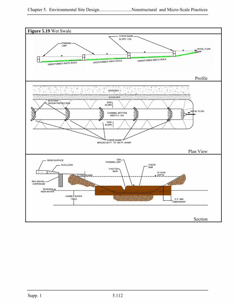
Chapter 5. Environmental Site Design............................Nonstructural and Micro-Scale Practices
Supp. 1 5.112
Figure 5.19 Wet Swale
Profile
Plan View
Section

Chapter 5. Environmental Site Design.............................Nonstructural and Micro-Scale Practices
M-9. Enhanced Filters An enhanced filter is a modification applied to specific practices (e.g., micro-bioretention) to provide water quality treatment and groundwater recharge in a single facility. This design variant uses a stone reservoir under a conventional filtering device to collect runoff, remove nutrients, and allow infiltration into the surrounding soil. Applications: The structural stormwater filtering systems in Chapter 3 and the micro-filtering structures above can be modified relatively easily for most development projects. Depending on soil conditions, a stone reservoir can be sized appropriately to provide Rev for the drainage area to the system. These practices are subject to the same constraints and design requirements as conventional and micro-scale filters. Performance: When designed according to the guidance provided below, enhanced filters may be used to address Rev for the contributing impervious area using the percent volume method. When coupled with other properly designed structural or micro-scale practices, the combined system will address the ESD sizing criteria. Constraints: The following constraints are critical when considering the use of enhanced filters to capture and treat stormwater runoff:
Space: The surface area of a typical enhanced filter is dependent on the design of the practice above. Similarly, the size and distribution of open areas within a project (e.g., parking lot islands, landscaped areas) must be considered early during a project’s planning and design if these practices are used.
Enhanced filters should not be used in areas where their operation may create a risk for basement flooding, interfere with subsurface sewage disposal systems, or affect other underground structures.
Soils: Soil conditions are important when designing enhanced filters. Local soil type is a primary factor for determining Rev and in sizing the stone reservoir.
Subsurface water conditions (e.g., water table) will help determine the stone reservoir thickness used. The probability of practice failure increases if the reservoir intercepts groundwater. Therefore, enhanced filter practice inverts should be above local groundwater tables.
5.113 Supp.1

Chapter 5. Environmental Site Design............................Nonstructural and Micro-Scale Practices
Hotspot Runoff: Enhanced filters should not be used to treat hotspots that generate higher concentrations of hydrocarbons, trace metals, or toxicants than are found in typical stormwater runoff and may contaminate groundwater.
Infrastructure: The location of existing and proposed buildings and utilities (e.g., water
supply wells, sewer, storm drains, electricity) will influence the design and construction of enhanced filters.
Design Guidance: The following conditions should be considered when designing enhanced filters:
Conveyance: Runoff shall enter the stone reservoir in a safe and non-erosive manner. Typically, runoff flows through the upper scale practice, into the stone reservoir and infiltrates into the ground. As the reservoir fills, an underdrain system is used to discharge treated stormwater safely downstream. Underdrains may be connected to other micro-scale practices or open or closed storm drain systems. All structural and micro-scale filters should be designed off-line whenever possible. A flow splitter should be used to divert excess runoff away from the filter media to a stable, downstream conveyance system. If bypassing these practices is impractical, internal overflow devices (e.g., elevated yard inlet) may be used.
Treatment: Enhanced filters shall meet the following conditions:
o Enhanced filters shall be coupled with properly designed filters to address both ESD
and Rev requirements. o At a minimum, enhanced filter reservoirs shall be designed to store the Rev. The
stone reservoir volume is equal to the surface area multiplied by depth divided by the porosity (n) of the stone [Volume = Surface Area (ft2) x Depth (ft) x 0.4].
o When using Variation A, the stone reservoir (#57 stone preferred) shall be at least 12 inches thick below the underdrain.
o A 12-inch layer of sand or pea gravel (⅛ to ⅜ inch stone) may be used to act as a bridging layer between the stone reservoir and subsurface soils.
o The invert of the stone reservoir shall be separated at least four feet (two feet on the lower Eastern Shore) from the seasonal high water table.
Setbacks:
o Enhanced filters shall be located at least 25 feet from septic systems, 100 feet from
unconfined water supply wells, and 50 feet from confined water supply wells.
o Enhanced filters shall be sized and located to meet minimum local requirements for clearance (both vertical and horizontal) from sewer and water lines. Designs may need to include special protection if underground utilities cross through enhanced filters.
Supp. 1 5.114

Chapter 5. Environmental Site Design.............................Nonstructural and Micro-Scale Practices
Observation Wells: An observation well consisting of an anchored, 4 to 6-inch diameter perforated pipe shall be provided. The top of the observation well shall be at least six inches above grade.
Construction Criteria: The following items should be addressed during the construction of projects with enhanced filtering practices:
Erosion and Sediment Control: Enhanced filters shall not be used as sediment control practices (e.g., sediment traps). Enhanced filters should not be constructed until the contributing drainage area is stabilized. Construction runoff shall be directed away after initial rough grading.
Soil Compaction: Existing soils in the location of enhanced filters should be scarified to
maximize infiltration. Construction shall be performed with lightweight, wide-tracked equipment to minimize disturbance and compaction.
Reservoir Installation: Stone for the reservoir system should be clean, washed, and free of
fines. Stone should be placed in horizontal layers (six inches per lift maximum) over the entire area of the practice using excavators or backhoes operating adjacent to the practice.
Inspection:
Regular inspections shall be made during the following stages of construction:
o During excavation to subgrade. o During placement of gravel, and installation of underdrain systems and observation
wells. o At all stages required for the ESD practice located above the enhanced filter.
Maintenance Criteria: Enhanced filters require minimal maintenance in addition to that needed for the practice above to ensure optimum performance. Generally, maintenance is the same as that used to keep the primary practice in good condition. Additional measures include making sure there is no water in the observation well. The presence of water 48 hours after a rain event indicates that the enhanced filter may be clogged and need replacement.
5.115 Supp.1

Chapter 5. Environmental Site Design............................Nonstructural and Micro-Scale Practices
Supp. 1 5.116
Figure 5.20 Enhanced Filters
Section -Variation 1
Section – Variation 2

Chapter 5. Environmental Site Design.................................................................... Redevelopment
Section 5.5 Redevelopment 5.5.1 Introduction Redevelopment is defined as any construction, alteration, or improvement performed on sites where the existing land use is commercial, industrial, institutional, or multifamily residential and existing site impervious area exceeds 40%. The term “site” is defined as a single tract, lot, parcel of land, or combination of tracts, lots, parcels of land that are in one ownership, or are contiguous and in diverse ownership where development is to be performed as part of a unit, subdivision or project. Therefore, when the total site impervious area under existing conditions exceeds the 40% threshold, redevelopment requirements will apply. When calculating site imperviousness, the local approving agency may allow lands protected by forest preservation, conservation easements, or other mechanism to be subtracted from the total site area. This will create incentive to preserve and protect natural resources in redevelopment projects. 5.5.2 Redevelopment Policy As described above, the 40% site impervious area threshold will determine whether a project will be regulated as new development or redevelopment. When redevelopment requirements apply, all existing impervious areas located within a project’s limit of disturbance (LOD) are required for management. Because redevelopment projects present a wide range of constraints and limitations, the policy below allows for flexibility and an evaluation of options that can work in conjunction with broader watershed goals and local initiatives. 1. Stormwater management shall be addressed for redevelopment according to the following
criteria:
a. Reduce existing impervious area within the LOD by at least 50%; or b. Implement ESD practices to the MEP to provide water quality treatment for at
least 50% of existing impervious area within the LOD; or c. Use a combination of impervious area reduction and ESD implementation for at
least 50% of existing impervious areas.
2. Alternative stormwater management measures may be used to meet the requirements above provided that the developer satisfactorily demonstrates to the approving authority that impervious area reduction and ESD have been implemented to the MEP. Alternative stormwater management measures include but are not limited to:
a. An on-site structural BMP; or b. An off-site structural BMP to provide water quality treatment for an area equal to
or greater than 50% of existing impervious areas; or c. A combination of impervious area reduction, ESD implementation, and on-site or
off-site structural BMP for an area equal to or greater than 50% of existing impervious area within the LOD.
5.117 Supp.1

Chapter 5. Environmental Site Design.................................................................... Redevelopment
3. An approving agency may develop separate programmatic policies for providing water quality treatment for redevelopment projects when the above requirements cannot be met. These policies shall be reviewed and approved by MDE and may include but are not limited to:
a. Retrofitting existing structural BMPs; b. Stream restoration; c. Trading policies that involve other pollution control programs; or d. Watershed management plans.
4. Stormwater management shall be addressed according to new development requirements
for any net increase in impervious area. 5.5.3 Management Considerations
Stormwater management requirements for redevelopment will apply to existing impervious areas within the project LOD. Impervious area is defined as any surface that does not allow stormwater to infiltrate into the ground. As a matter of policy, if gravel is compacted to the point where it will no longer infiltrate, then it is impervious. Any gravel driveway or parking area that is regularly used is likely to become impervious over time. However, a gravel road that is infrequently used may be considered pervious. These determinations should be done on a case-by-case basis. Alternative surfaces may be used to meet redevelopment requirements. However, when designing to meet runoff reduction requirements the appropriate curve number should be used according to the design specifications in this Chapter. These practices however, are not considered permeable surfaces, and may be regulated differently by other State and local programs. Redevelopment activities may occur on a site where a BMP is providing treatment for existing impervious areas. These BMPs shall be inspected and their performance verified. The requirements described in 5.5.2 apply to existing impervious areas that are not treated by BMPs meeting current design standards. Existing BMPs may be retrofitted to current standards and treat additional impervious areas to meet redevelopment requirements. 5.5.4 Design Process for Redevelopment All redevelopment projects shall be subject to the Design process for Redevelopment as outlined in the step wise procedures in Figure 5.21. Section 5.1 of this chapter describes the design process for all development in Maryland that includes a comprehensive review and approval of concept, site development, and final plans by the local review agencies. These procedures will also apply to redevelopment projects and the guidance provided in Section 5.1 of this chapter should be referenced for more specific detail at each step and for a check list of items required for interim reviews. The process described below outlines the steps in Figure 5.21 and will highlight considerations specific to the design of a
Supp. 1 5.118

Chapter 5. Environmental Site Design.................................................................... Redevelopment
redevelopment project. Approving agencies shall use the process outlined in Figure 5.21 as an enforceable mechanism during review of the plan. Documentation that all steps were followed during project development and specific rationale to support the proposed design shall be required. Step 1. Concept Phase: Develop a site map and assess existing natural resources as described in Section 5.1.3.1. Existing buildings, impervious areas, utilities, storm drain systems, neighboring properties, and all environmental and infrastructure constraints are identified. Opportunities to reduce existing and proposed impervious cover by using site design techniques and alternative surfaces are evaluated. The approximate locations of proposed impervious areas are identified and opportunities for using ESD practices are evaluated. Additionally the developer shall provide a narrative to the appropriate review agencies to support the design for concept approval. Step 2. Submit Concept Plan: Approval agencies provide review and comment back to the developer. Concept plan approval must be given by the appropriate review agencies before proceeding to the site development phase. Step 3. Site Development Phase: Incorporate comments from review agencies and finalize proposed site layout indicating how existing and proposed impervious areas are hydrologically connected to landscaped features (e.g., islands, vegetated planters, and green spaces). Evaluate opportunities for implementing ESD practices on open space and landscaped areas for storage, filtration, infiltration, and water quality treatment of stormwater runoff. Develop an erosion and sediment control plan and an overlay plan. Provide a narrative to the appropriate review agencies to support the design for site development approval. Step 4. Submit Site Development Plan: Approval agencies provide review and comment on the site development plan back to the developer. All reasonable options for meeting stormwater management requirements using ESD planning techniques and practices have been exhausted. Approval agencies will provide comments and suggestions for final design. These may include potential management strategies in the event that stormwater requirements cannot be met using ESD. Site development plan approval must be given by the appropriate review agencies before proceeding to final design. Step 5A. Final Design Phase – A: After all reasonable ESD options have been exhausted, evaluate alternative management strategies including on-site and off-site structural BMPs and design according to Chapter 3. Review agencies should provide guidance on acceptable stormwater treatment measures that may include retrofit projects, stream restoration, pollution trading, watershed management plans, or other approved practices. Step 5B. Final Design Phase – B: Finalize plans and address any remaining comments from the appropriate review agencies. Step 6. Submit Final Plans: Final stormwater management and erosion and sediment control plans are submitted for approval. The designer needs to demonstrate that on-site ESD practices have been implemented to the MEP.
5.119 Supp.1

Chapter 5. Environmental Site Design.................................................................... Redevelopment
Supp. 1 5.120
Figure 5.21 Design Process for Redevelopment
Chapter 5. Environmental Site Design.................................................................... Special Criteria
Section 5.6 Special Criteria for Sensitive Waters 5.6.1 Introduction In Maryland, there are several different types of sensitive watersheds, each with unique features or regulatory requirements. In some watersheds, enhanced pollutant removal may be needed to protect drinking water supply or shellfish harvesting. In others, temperature increases caused by new development may need to be mitigated to preserve coldwater habitat. In addition to these special needs, there are numerous State programs (e.g., Critical Areas, Wetlands and Waterways, Forest Conservation) that regulate activities within receiving waters. This section presents additional criteria that should be considered when designing projects in sensitive watersheds. This section also identifies requirements from other State regulatory programs that will influence ESD implementation. 5.6.2 Water Quality Standards The purpose of Maryland’s water quality standards is to protect, maintain, and improve surface water quality. Two of the components of these standards are the Designated Uses and water quality criteria to protect them. Each major stream segment in Maryland is assigned one of the following Designated Uses: • USE I & I-P: Water Contact Recreation and Protection of Nontidal Warmwater Aquatic Life
where P indicates public water supply or reservoir protection areas. • USE II & II-P: Support of Estuarine and Marine Aquatic Life and Shellfish Harvesting • USE III & III-P: Nontidal Cold Water • USE IV & IV-P: Recreational Trout Waters For each designated use, specific water quality criteria are designed to protect aquatic life and human health. Typically, there are numeric criteria for toxics, dissolved oxygen, bacteria, and temperature (e.g., 5 mg/l for dissolved oxygen). There are also narrative standards that are used for other pollutants (e.g., oil, grease, odor) where specific values are impractical. For the majority of Maryland’s waters, these criteria represent minimum standards for the support of balanced indigenous populations and contact recreation commonly known as "fishable/swimmable." For higher quality waters that exceed fishable/swimmable standards, the existing water quality conditions must be maintained. 5.6.3 ESD Implementation and Watershed Use Stormwater management decisions are influenced by the nature and quality of the receiving waters. Therefore, Designated Uses should be identified during the initial site and resource mapping steps. In most cases, the majority of water quality concerns in a given watershed can be addressed through the use of ESD to the MEP. For example, maximizing the use of ESD is a critical component of any approval for additional discharges to higher quality waters identified in Maryland’s Tier II Antidegradation Policy. However, in Use III and IV, ESD implementation alone may not be sufficient to maintain critical in-stream temperatures.
5.121 Supp.1

Chapter 5. Environmental Site Design.................................................................... Special Criteria
5.6.4 At-Source Techniques for Mitigating Thermal Impacts Temperature increases caused by development impact the quality of coldwater streams. Temperatures should not exceed 68º F in Use III and 75º F in Use IV streams or the ambient water temperature, whichever is greater. The lethal temperatures for brook, and brown and rainbow trout are 72º and 82º F, respectively. Therefore, one of the primary design objectives is to prevent stream warming and maintain habitat quality for coldwater aquatic life. Implementing ESD to the MEP, including using infiltration where appropriate, will help mitigate many of the thermal impacts associated with development. However, additional techniques may be needed to limit thermal impacts at the source. In a study prepared for MDE in 1990 by the Metropolitan Washington Council of Governments, it was determined that “[i]mperviousness together with local meteorological conditions had the largest influence on urban stream temperatures” (Thermal Impacts Associated with Urbanism and Stormwater Best Management Practices, John Galli, 1990). This study reported that as watershed imperviousness increased, progressively smaller rainfall depths were needed to produce large stream temperature fluctuations. Clearly, reducing imperviousness will help reduce thermal impacts and techniques for accomplishing this are listed in Section 5.1. The color of impervious surfaces also affects temperature increases. Darker surfaces like asphalt pavement or shingles absorb solar radiation, elevating temperatures as this energy is transferred as heat to surrounding areas, including stormwater runoff. Lighter colored materials like grey or white concrete reflect solar radiation resulting in less elevated temperatures. A material’s ability to reflect solar heat is measured as its Solar Reflectance Index or “SRI” and varies from 0 (a black surface) to 100 (a white surface) and above. In thermally-sensitive watersheds, designers should consider using materials with SRI values greater than 29 (see Table 5.9) for paving and steep-sloped (≥2:12) roofing, and materials with SRI values greater than 78 for low-sloped (≤2:12) roofing. Table 5.9 Solar Reflectance Indices (SRI) for Typical Paving & Roofing Materials Paving Materials: Condition SRI
Asphalt New 0 Weathered 6 Gray Concrete New 35 Weathered 29 White Concrete New 86 Weathered 45
Roofing Materials: Gray Asphalt Shingles 22 Gray EPDM (Rubber) 21 Light Gravel on Built-Up Roof 37 White-Coated Gravel on a Built-Up Roof 79 White EPDM (Rubber) 84 White PVC 104
Source: LEED®-NC for New Construction Reference Guide Ver. 2.2 (USGBC, October 2005)
Supp. 1 5.122

Chapter 5. Environmental Site Design.................................................................... Special Criteria
Another option for mitigating thermal impacts at the source is to shade buildings and paved areas from the sun. Trees, large shrubs, and non-invasive vines on trellises can be used to screen these areas from the sun and cool the air through evapotranspiration. The full benefits of shading may not be realized until the trees and shrubs mature. Depending on the age and type of plants used, this may be several years. In the interim, any receiving waters may be degraded and resources lost as a result of temperature increases. When using this technique, designers should strive to provide shade within five years of project completion. 5.6.5 Additional Techniques for Mitigating Thermal Impacts While thermal impacts are primarily caused by increases in impervious area, stormwater management practices, including ESD techniques, may contribute to the problem. When designing these techniques for use in coldwater areas, minimizing temperature increases is a primary concern. The following techniques will help reduce thermal impacts associated with ESD practices:
Maximize the infiltration capacity of each practice. Increasing infiltration reduces the amount of surface runoff and lowers the thermal energy flowing into coldwater streams.
Design filtering practices (e.g., micro-bioretention) so that underdrains are at least four feet
below the surface. Soil temperatures at this depth are cooler and fluctuate little in response to surface weather conditions. As runoff flows through, thermal energy is dissipated and effluent temperatures are decreased. If overflow and conveyance connection constraints limit underdrain depth, use the enhanced filter option 2 (see M-9, Section 5.4.3). In this variant, the perforated underdrain is located at the bottom of a stone reservoir and below the outlet pipe. As the water surface elevation within the reservoir rises above the invert of the outlet pipe, cooler water is siphoned from the bottom.
Use shade-producing plants in landscaped practices. As discussed above, trees, shrubs, and
non-invasive vines on trellises can be used to screen impervious areas from the sun. 5.6.6 Other Resources In addition to the various Designated Uses, designers must also consider sensitive conditions and design requirements associated with other programs that regulate development activities related to critical resources. Similar to water quality concerns, most of these may also be addressed through the use of ESD to the MEP. However, there are additional concerns like buffer widths, construction materials used, or wetland types that may need to be considered. This section identifies some of these program-specific requirements.
5.123 Supp.1
Chapter 5. Environmental Site Design.................................................................... Special Criteria
Wetlands & Waterways Wetlands are essential natural resources that provide fish and wildlife habitat, flood protection, and water quality enhancement. These sensitive areas are impacted by even the smallest of changes in hydrology or water quality. For this reason, stormwater management measures should not be located within nontidal wetlands and their buffers, tidal wetlands, and 100-year floodplains. This includes many of the ESD techniques listed in this Chapter. If stormwater management facilities must be located within these areas, State and federal permits are required. In addition to the above restrictions, runoff from new development and redevelopment must be treated prior to discharging directly into jurisdictional wetlands or waters of the State. In most cases, using ESD to MEP will provide adequate treatment and meet this requirement. Where discharges are permitted, there are additional concerns. When implementing ESD within areas of sensitive wetlands with unusual or unique plant communities like bogs, Delmarva bays, or Wetlands of Special State Concern, designers should incorporate features and materials that complement or mimic local natural conditions. For example, bogs are nutrient-deficient, acidic environments where runoff pH is critical. In these areas, designers should specify the use of native or locally available materials that are acidic (pH < 7) like granite or sandstone instead of limestone or marble (pH > 7) for riprap in conveyance channels and energy dissipaters. Likewise, landscaping should promote native plants that match both the conditions found within ESD practices and local wetland communities. In addition to using local or native materials and plants, designers should consider how runoff is conveyed to wetlands. Storm drainage systems are usually designed to discharge directly into wetlands and/or floodplains. This approach minimizes the ecological interaction that occurs between wetland areas and adjacent buffers. Using more natural channel designs (e.g., coastal plains outfalls, step/pool systems, bioswales) or promoting sheetflow to convey runoff from ESD practices into wetlands connects and promotes interaction within these areas Maryland’s Critical Areas Maryland’s Critical Area Act recognizes that the land immediately surrounding the Chesapeake and Atlantic Coastal Bays and their tributaries has the greatest potential to affect water quality and wildlife habitat. Therefore, all land within 1,000 feet of tidal waters or adjacent tidal wetlands is designated as the “Critical Area.” While the State Critical Area Commission provides oversight and reviews some development projects, each appropriate County and municipality enforces this law. All development located within the Critical Area must address additional criteria. Some provisions of these criteria, like those relating to the protection of habitat, are applied uniformly throughout the Critical Area. Others provisions that may impact ESD implementation are related to water quality and site imperviousness and are specific to land classifications discussed below.
Supp. 1 5.124
Chapter 5. Environmental Site Design.................................................................... Special Criteria
Within the Critical Area, land is designated as either Intensely Developed Area, Limited Development Area, or Resource Conservation Area (IDA, LDA, & RCA, respectively) based on uses that existed at the time the local programs were adopted. The IDAs are those areas of concentrated development where there is little natural habitat. Any new development and redevelopment projects within the IDA must include stormwater management practices to reduce post-development phosphorus loads to at least 10% below pre-developed levels. Commonly known as the 10% Rule, this requirement may be addressed using many of the ESD practices described in this Chapter or by using structural practices found in Chapter 3. While implementing ESD to the MEP should meet or exceed phosphorus reduction requirements in most cases, applicants may be required to use the Critical Areas methodology to demonstrate compliance with the 10% Rule as part of the plan approval process. Additional guidance for addressing the 10% Rule within the IDA may be found in the Critical Area 10% Rule Guidance Manual (MDNR, 2003). LDAs are those regions where development density is low to moderate and wildlife habitat is not dominated by agriculture, wetlands, forests, or other natural areas. Similarly, RCAs are characterized by the dominance of agriculture or protected resources like forests or wetlands. Within these areas, new development or redevelopment must address standard water quality requirements, conserve natural areas, and incorporate corridors to connect wildlife and plant habitat. To accomplish these goals, imperviousness, alternative surfaces, or “lot coverage” is generally limited to 15% of the property or project area. There are also strict limits on clearing of existing woodland or forests. All clearing of these areas requires at least a 1:1 replacement. To protect habitat, a forested buffer is required on all new development in all three land designations. Extending a minimum of 100 feet from the Mean High Water Line of tidal waters or the landward edge of tidal wetlands and tributary streams, this buffer acts as a water quality filter and protects important riparian habitat within the Critical Area. This distance may be expanded to include adjacent sensitive areas like hydric or highly erodible soils or steep slopes. If it is within a subdivision in the RCA, the minimum width of the buffer is 200 feet. Disturbance associated with new development is generally prohibited within the buffer, and, accordingly, stormwater practices (e.g., micro-scale practices, structural facilities) cannot be located within it. Forest Conservation Act The Maryland Forest Conservation Act (FCA) was enacted in 1991 to minimize the loss of forests during land development. As a result, identifying and protecting forests is an integral part of the development process. The primary areas targeted for protection include forests adjacent to streams or wetlands, located on steep slopes, or within or adjacent to forest blocks or wildlife corridors. Any activity requiring a subdivision application, grading permit, or erosion and sediment control plan approval on areas exceeding 40,000 square feet is subject to the FCA and a Forest Conservation Plan may be required. The Forest Conservation Plan includes a map and narrative that describes how existing forested and sensitive areas will be protected, if afforestation will be required, and how any replanted trees will be protected. While implementation is not directly affected by the FCA, trees may be planted within ESD practices and associated buffers located adjacent to critical habitat, steeply sloping ground and highly
5.125 Supp.1

Chapter 5. Environmental Site Design.................................................................... Special Criteria
Supp. 1 5.126
erodible soils, large forest tracts, 50-foot stream buffers, or similar areas. Additionally, landscaping within ESD practices may be used to meet afforestation requirements when it exceeds 2,500 square feet, is at least 35 feet wide and protected by an approved landscape management plan.