environmental systems and services - air pollution control ... · environmental systems and...
TRANSCRIPT

Jet III Pulse Jet Dust Collectors
Environmental Systems and Services - Air Pollution Control
Siemens Wheelabrator Jet III
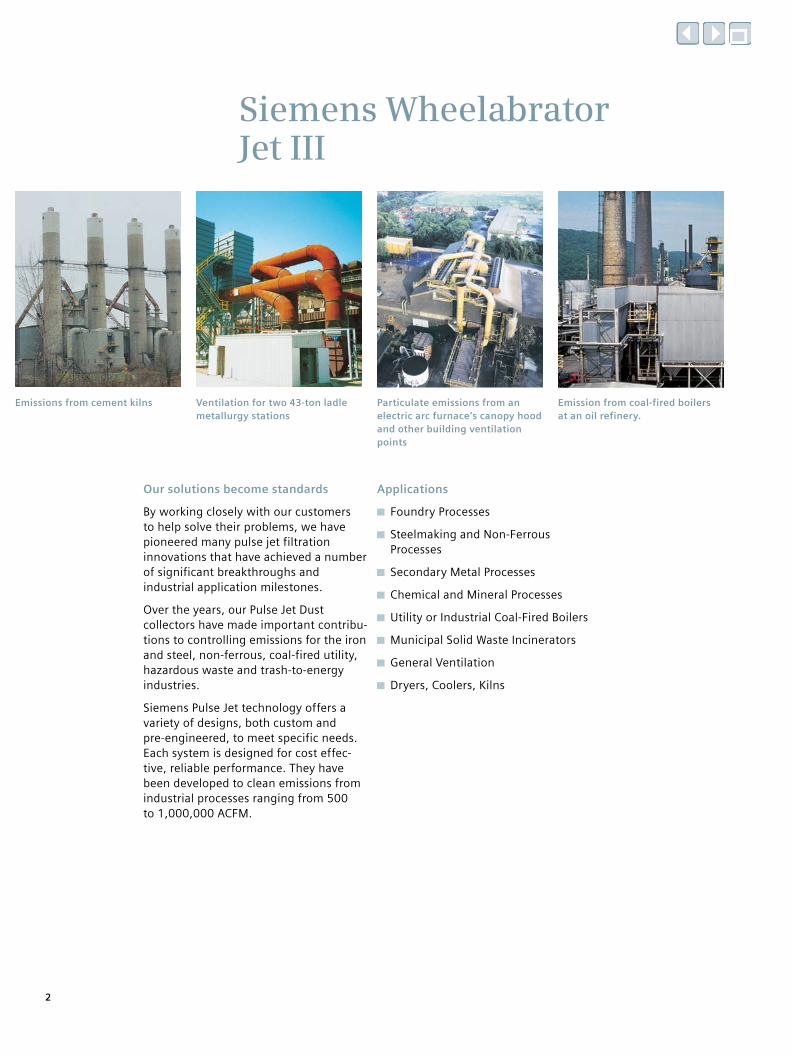
Our solutions become standards
By working closely with our customers to help solve their problems, we have pioneered many pulse jet filtration innovations that have achieved a number of significant breakthroughs and industrial application milestones.
Over the years, our Pulse Jet Dust collectors have made important contribu-tions to controlling emissions for the iron and steel, non-ferrous, coal-fired utility, hazardous waste and trash-to-energy industries.
Siemens Pulse Jet technology offers a variety of designs, both custom and pre-engineered, to meet specific needs. Each system is designed for cost effec-tive, reliable performance. They have been developed to clean emissions from industrial processes ranging from 500 to 1,000,000 ACFM.
Applications
Foundry Processes
Steelmaking and Non-Ferrous Processes
Secondary Metal Processes
Chemical and Mineral Processes
Utility or Industrial Coal-Fired Boilers
Municipal Solid Waste Incinerators
General Ventilation
Dryers, Coolers, Kilns
Emissions from cement kilns Particulate emissions from an electric arc furnace’s canopy hood and other building ventilation points
Ventilation for two 43-ton ladle metallurgy stations
Emission from coal-fired boilers at an oil refinery.
2

Pulse Jet Dust Collectors
Continuing support
Our Aftermarket Services Department can:
Monitor, test and inspect your collector on site
Train your operating and maintenance personnel
Provide replacement parts
Upgrade or rebuild your equipment
For more information please contact us at 1-800-327-8727.
Ongoing JET III research and development
Siemens technical innovation and extensive knowledge are the result of our continuing commitment to product research and development, building on Wheelabrator brand technology.
One Source for Clean Air Technology
Because Siemens is a single-source supplier for all aspects of fabric filter systems, we can offer our customers the right technology for their application. This broad range of capabilities includes process analysis, system design, erection, start-up, and complete aftermarket services with comprehensive technical support, service, operator training and replacement parts for our equipment.
Emissions from a municipal solid waste facility.
Gaseous and fluoride emissions from an aluminum reduction plant.
Emissions from a pulverized coal boiler.
Primary and secondary emissions from an AOD vessel
3

Clean floor design
Pulse manifold pipe
Clean air plenumDouble diaphragm valve
Pulse headerWalk-in access
Heavy dutyhousing
and hopperconstruction
Filter bags
Inlet with gasdistribution baffle
Dust discharge
4
Siemens Wheelabrator Jet III

Tube sheet and bag attachment
Die-formed cups for added strength
Positive seal against dust leakage
Fast bag attachment without tools
Simple, one-step bagging
Improves clean-side work area
Our Pulse Jet Dust Collector uses a drawn-cup tube sheet. The tube sheet is seal-welded into the housing to create a positive seal.
The tube sheet features patented “snap-ring” bag sealing and offers a fast, one-man, one-step process for bag installation. Our tube sheet, acting as a natural bagging fixture, allows cage insertion or removal directly from the tube sheet and bags.
Venturi and cage
Designed and tested to reduce com-pressed air consumption
Venturi self-aligns for easy installation and efficient pulse cleaning
Simple interlock for rapid assembly
Quality bag support cages
The high-gain throat of the dust collector venturi is capable of cleaning more surface area of filter media with less compressed air. This provides effective cleaning of 6-inch diameter bags up to16-feet long with the collector on stream.
The venturi snap locks on the bag support cage, which is then simply inserted into an installed bag in the tubesheet.
5
Pulse Jet Dust Collectors

Jet III Pulse cleaning system
Our pulse cleaning hardware is designed to clean with minimum air consumption for maximum energy savings. More filter cloth area is cleaned with each pulse. Field tested on tough industrial applica-tions, the cleaning system contributes to prolonging filter bag life.
Header
The compressed air header is designed for space saving, positive alignment and convenient mounting of air valves. Header assemblies are sectionalized to permit local isolation for maintenance without shutting down the entire system. The system requires a low line pressure for energy conservation.
Double diaphragm air valve
Siemens double diaphragm air valves provide the power for cleaning up to 18 bags per row. Fewer valves per square foot of cloth mean less maintenance and fewer parts.
Manifold
Extensive research and development by Siemens Wheelabrator has resulted in a unique, energy efficient blow pipe for pulse cleaning. The 1-1/2 inch diameter manifold pipes are drilled with offset and variable size holes to ensure maximum even flow through all venturis. The fit of the manifold with the plenum is positive to maintain alignment. For bag inspection and/or removal, the manifold can be removed with minimum effort and without special tools.
Simple design uses fewer parts
Easy to maintain
Reduces energy costs
6
Jet III On-line cleaning
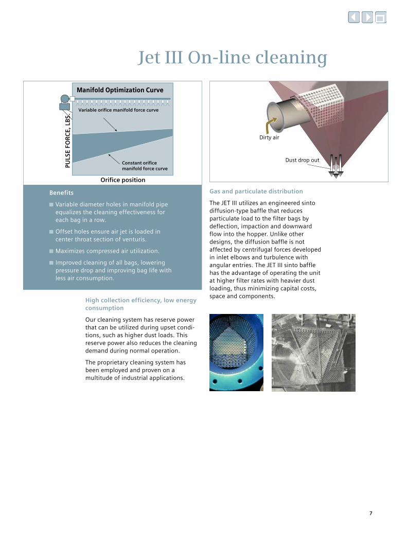
Variable orifice manifold force curve
Manifold Optimization Curve
Constant orificemanifold force curvePU
LSE
FOR
CE,
LB
S.
Orifice position
Dust drop out
Dirty air
High collection efficiency, low energy consumption
Our cleaning system has reserve power that can be utilized during upset condi-tions, such as higher dust loads. This reserve power also reduces the cleaning demand during normal operation.
The proprietary cleaning system has been employed and proven on a multitude of industrial applications.
Gas and particulate distribution
The JET III utilizes an engineered sinto diffusion-type baffle that reduces particulate load to the filter bags by deflection, impaction and downward flow into the hopper. Unlike other designs, the diffusion baffle is not affected by centrifugal forces developed in inlet elbows and turbulence with angular entries. The JET III sinto baffle has the advantage of operating the unit at higher filter rates with heavier dust loading, thus minimizing capital costs, space and components.
Benefits
Variable diameter holes in manifold pipe equalizes the cleaning effectiveness for each bag in a row.
Offset holes ensure air jet is loaded in center throat section of venturis.
Maximizes compressed air utilization.
Improved cleaning of all bags, lowering pressure drop and improving bag life with less air consumption.
7
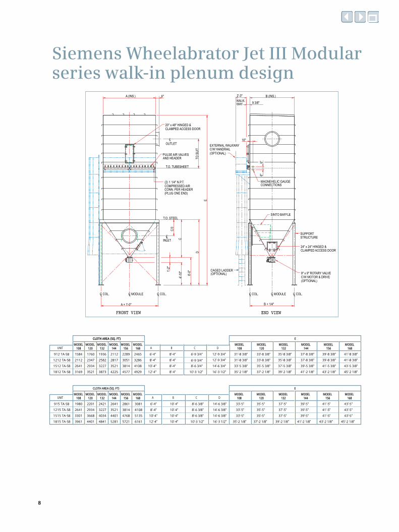
Siemens Wheelabrator Jet III Modular series walk-in plenum design
FRONT VIEW END VIEW
D
C
1'-2"
C/3
A (INS.) B (INS.)
B + 1/4"A + 1'-0"
6"6"
10"
4'-10
"
E
TO S
UIT
CLINLET
OUTLETCL
C COL.L C COL.LC COL.L C COL.LC MODULEL
20" x 48" HINGED &CLAMPED ACCESS DOOR
(2) 1 1/4" N.P.T.COMPRESSED AIRCONN. PER HEADER(PLUG ONE END)
CAGED LADDER(OPTIONAL)
CLAMPED ACCESS DOOR24" x 24" HINGED &
SINTO BAFFLE
SUPPORTSTRUCTURE
C MODULEL
T.O. TUBESHEET
T.O. STEEL
PULSE AIR VALVESAND HEADER
6'-0"
MAGNEHELIC GAUGECONNECTIONS
EXTERNAL WALKWAYC/W HANDRAIL(OPTIONAL)
2'-3"
9 3/8"WALK-WAY
(OPTIONAL)C/W MOTOR & DRIVE9" x 9" ROTARY VALVE
6"
912 TA-SB
1212 TA-SB
1512 TA-SB
1812 TA-SB
1936
2582
3227
3873
29342641
3169 3521
2112
1584
2347
1760
3521
4225
2112
2817
MODEL108UNIT
CLOTH AREA (SQ. FT)
MODEL120
MODEL132
MODEL144
3814
4577
3051
156
2289
MODEL
4108
4929
3286
168
2465
MODEL MODEL132
E
MODEL108
MODEL120 168
MODEL144
MODEL156
MODEL
14'-6 3/4"
16'-3 1/2"
12'-9 3/4"
10'-4"
12'-4"
8'-4"
6'-4"
A
8'-6 3/4"
10'-3 1/2"
6'-9 3/4"
B C
31'-8 3/8"
33'-5 3/8"
35'-2 1/8"
6'-9 3/4" 12'-9 3/4" 31'-8 3/8" 33'-8 3/8"
37'-2 1/8"
35'-5 3/8"
33'-8 3/8"
35'-8 3/8"
39'-2 1/8"
37'-5 3/8"
35'-8 3/8"
37'-8 3/8"
41'-2 1/8"
39'-5 3/8"
37'-8 3/8"
39'-8 3/8"
43'-2 1/8"
41'-5 3/8"
39'-8 3/8"
41'-8 3/8"
45'-2 1/8"
43'-5 3/8"
41'-8 3/8"
915 TA-SB
1215 TA-SB
1515 TA-SB
1815 TA-SB
2421
3227
4034
4841
36683301
3961 4401
2641
1980
2934
2201
4401
5281
2641
3521
MODEL108UNIT
CLOTH AREA (SQ. FT)
MODEL120
MODEL132
MODEL144
4768
5721
3814
156
2861
MODEL
5135
6161
4108
168
3081
MODEL MODEL132
E
MODEL108
MODEL120 168
MODEL144
MODEL156
MODEL
14'-6 3/8"
14'-6 3/8"
16'-3 1/2"
14'-6 3/8"
10'-4"
12'-4"
8'-4"
6'-4"
A
8'-6 3/8"
10'-3 1/2"
8'-6 3/8"
8'-6 3/8"
B C
33'-5"
33'-5"
33'-5"
35'-2 1/8"
35'-5"
35'-5"
35'-5"
37'-5"
37'-5"
37'-5"
39'-5"
39'-5"
39'-5"
41'-5"
41'-5"
41'-5"
43'-5"
43'-5"
43'-5"
37'-2 1/8" 39'-2 1/8" 41'-2 1/8" 43'-2 1/8" 45'-2 1/8"
D
D
8'-4"
8'-4"
8'-4"
8'-4"
10'-4"
10'-4"
10'-4"
10'-4"
8

Siemens Wheelabrator Jet III Modular series roof access door design
B + 1/4"
FRONT VIEW END VIEW
4'-10
"
A (INS.) B (INS.) 6"
A + 1'-0"
6"
6"6"
1'-2"
6'-0"
D
C
C/3
CLINLET
C OUTLETL
C COL.L C COL.LC COL.L C COL.L
CAGED LADDER(OPTIONAL)
CLAMPED ACCESS DOOR24" x 24" HINGED &
9" x 9" ROTARY VALVEC/W MOTOR & DRIVE
SINTO BAFFLE
SUPPORTSTRUCTURE
ROOF HANDRAIL
MAGNEHELIC GAUGECONNECTIONS
HINGED ROOFDOORS
E
2'-6 3
/8"
(OPTIONAL)
T.O. T
UBES
HEET
(OPTIONAL)
CONN. PER HEADER(PLUG ONE END)
COMPRESSED AIR(2) 1 1/4" N.P.T.
TO S
UIT
C MODULEL LC MODULE
T.O. STEEL
PULSE AIR VALVESAND HEADER3'-
6"
LC OUTLET
915 RA-SB
1215 RA-SB
1515 RA-SB
1815 RA-SB
2421
3227
4034
4841
36683301
3961 4401
2641
1980
2934
2201
4401
5281
2641
3521
MODEL108UNIT
CLOTH AREA (SQ. FT)
MODEL120
MODEL132
MODEL144
4768
5721
3814
156
2861
MODEL
5135
6161
4108
168
3081
MODEL MODEL132
E
MODEL108
MODEL120 168
MODEL144
MODEL156
MODEL
14'-9 3/8"
14'-9 3/8"
16'-3 1/2"
14'-9 3/8"
10'-4"
12'-4"
8'-4"
6'-4"
A
8'-9 3/8"
10'-3 1/2"
8'-9 3/8"
8'-9 3/8"
DC
26'-9 3/8"
28'-3 1/2"
26'-9 3/8"
26'-9 3/8"
29'-3 1/2"
27'-9 3/8"
30'-3 1/2"
28'-9 3/8"
31'-3 1/2"
29'-9 3/8"
32'-3 1/2"
30'-9 3/8"
33'-3 1/2"
31'-9 3/8"
28'-9 3/8"27'-9 3/8" 31'-9 3/8"29'-9 3/8" 30'-9 3/8"
28'-9 3/8"27'-9 3/8" 31'-9 3/8"29'-9 3/8" 30'-9 3/8"
912 RA-SB
1212 RA-SB
1512 RA-SB
1812 RA-SB
1936
2582
3227
3873
29342641
3169 3521
2112
1584
2347
1760
3521
4225
2112
2817
MODEL108UNIT
CLOTH AREA (SQ. FT)
MODEL120
MODEL132
MODEL144
3814
4577
3051
156
2289
MODEL
4108
4929
3286
168
2465
MODEL MODEL132
E
MODEL108
MODEL120 168
MODEL144
MODEL156
MODEL
10'-4"
12'-4"
8'-4"
6'-4"
A
8'-6 3/4"
10'-3 1/2"
7'-0 5/8"
B C
25'-0 5/8"
28'-3 1/2"
26'-6 3/4"
7'-0 5/8"
16'-3 1/2"
14'-6 3/4"
13'-0 5/8"
13'-0 5/8"
25'-0 5/8"
29'-3 1/2"
27'-6 3/4"
26'-0 5/8"
26'-0 5/8"
30'-3 1/2"
28'-6 3/4"
27'-0 5/8"
27'-0 5/8"
31'-3 1/2"
29'-6 3/4"
28'-0 5/8"
28'-0 5/8"
32'-3 1/2"
30'-6 3/4"
29'-0 5/8"
29'-0 5/8"
33'-3 1/2"
31'-6 3/4"
30'-0 5/8"
30'-0 5/8"
D
8'-7"
8'-7"
8'-7"
8'-7"
10'-7"
10'-7"
10'-7"
10'-7"
B
9

Siemens Wheelabrator Jet III Extended series walk-in plenum design
FRONT VIEW END VIEW
4'-10
"C
1'-1 1
/4"1'-
2"
1'-0"
C/3
A (INS.) B (INS.) 6"
B + 7 1/2"F G F
6"6"
TO S
UIT
E
10"
FIEL
D SP
LICE
T.O. T
UBES
HEET
FIEL
D SP
LICE
20" x 48" HINGED &CLAMPED ACCESS DOOR
(2) 1 1/4" N.P.T.COMPRESSED AIRCONN. PER HEADER(PLUG ONE END)
CAGED LADDER(OPTIONAL)
9" DIA. SCREWCONVEYOR C/WMOTOR & DRIVE(OPTIONAL)
9" x 9" ROTARY VALVESLAVE DRIVEN BY S/C(OPTIONAL)
SINTO BAFFLE(ONE PER INLET)
D
MAGNEHELIC GAUGECONNECTIONS
PULSE AIR VALVESAND HEADER
2'-3" 9 3/8"
C COL.LC COL.LC COL.LC COL.LC COL.L
24"x24" HINGED &CLAMPED ACCESSDOOR
C INLETSL
C OUTLETL
C COL.L
SUPPORTSTRUCTURE
EXTERNAL WALKWAYC/W HANDRAIL(OPTIONAL)
WALKWAY
C MODULEL
T.O. STEEL
C OUTLETL
4815 TA-SB
5115 TA-SB
5415 TA-SB
12910
13716
14523
11736
12470
13203
11223
11883
10562 14083
14963
15844
3615 TA-SB
3315 TA-SB
3015 TA-SB
2715 TA-SB
2415 TA-SB
2115 TA-SB
3915 TA-SB
4215 TA-SB
4515 TA-SB
8875
8069
10489
11296
12103
9682
9536
10269
11003
9242
9902
8582
7262
7922
6602
8069
8802
7335
11443
12323
13203
9682
8802
10562
CLOTH AREA (SQ. FT)
7262
6455
564851354621
5941
5281
6602
5868
108 120
6161
7042
7922
144132UNIT
1848417164
1540414303
16210
15257
17457
16430
13350
12396
14377
13350
10489
11443
9536
11296
12323
10269
7628
8582
6675
8215
9242
7188
156 168MODEL MODEL MODEL MODEL MODEL MODEL MODEL
120MODEL
108MODEL
E
MODEL132
MODEL144 156
MODEL168
7'-8"
10'-8"
9'-8"
8'-8"
12'-8"
9'-2"
10'-2"
11'-8"
10'-2"
11'-2"
12'-2"
12'-8"
11'-0"
11'-0"
12'-0"
9'-0"
11'-0"
9'-0"
C
22'-4"
32'-4"
34'-4"
36'-4"
30'-4"
28'-4"
26'-4"
24'-4"
18'-4"
20'-4"
16'-4"
14'-4"
BA
34'-5 1/4" 36'-5 1/4" 38'-5 1/4" 40'-5 1/4" 42'-5 1/4" 44'-5 1/4"
4817 TA-SB
5117 TA-SB
5417 TA-SB
14628
15543
16457
13301
14132
14963
12718
13466
11970 15960
16958
17955
3617 TA-SB
3317 TA-SB
3017 TA-SB
2717 TA-SB
2417 TA-SB
2117 TA-SB
3917 TA-SB
4217 TA-SB
4517 TA-SB
10057
9143
11886
12800
13714
10971
10807
11638
12470
10474
11222
9726
8229
8977
7481
9144
9976
8313
12968
13965
14963
10973
9975
11970
8228
7314
640058195237
6734
5985
7482
6650
6983
7980
8978
2094819455
1745716213
18374
17293
19784
18620
15132
14051
16293
15129
11889
12970
10808
12801
13965
11638
8647
9728
7566
9310
10474
8146
D F G
10'-4"
10'-4"
8'-9"
8'-9"
15'-10 1/4"
15'-10 1/4" 40'-5 1/4"36'-5 1/4"34'-5 1/4" 38'-5 1/4" 44'-5 1/4"42'-5 1/4"
156MODEL
30'-4"
16'-11 1/4"11'-8"
32'-4"
34'-4"
36'-4" 9'-10"
108MODEL
UNIT
16'-11 1/4"
168MODEL
CLOTH AREA (SQ. FT)
MODEL MODEL120 132
MODEL MODEL144 156
24'-4"
26'-4"
28'-4"
18'-4"
20'-4"
22'-4"
11'-8"14'-4"
16'-4"
A
9'-10"
B C 108MODEL
DMODEL
120MODEL
132
E
MODEL144
10'-2" 11'-0"
12'-0"
11'-0"
11'-0"11'-2"
12'-2"
12'-8"
9'-0"
9'-0"
12'-8"
9'-2"
10'-2"
9'-8"
10'-8"
11'-8"
MODEL168
7'-8"
8'-8"
F G
37'-6 1/4"35'-6 1/4" 39'-6 1/4" 41'-6 1/4" 45'-6 1/4"43'-6 1/4"
43'-6 1/4"37'-6 1/4"35'-6 1/4" 41'-6 1/4"39'-6 1/4" 45'-6 1/4"10

Siemens Wheelabrator Jet III Extended series roof access door design
END VIEWFRONT VIEW
C/3
6"6"6"
F
LC COL. LC COL.C COL.L
G F
C COL.L
B + 7 1/2"
INLETSLC
MAGNEHELIC GAUGECONNECTIONS
CLOUTLET
E
D
C
FIELDSPLICE
3'-6"
TUBESHEET
4'-10
"
(OPTIONAL)ROOF HANDRAIL
SUPPORTSTRUCTURE
B (INS.) 6"
LC COL. C COL.L
LCINLETS
1'-2"
1'-1 1
/4"2'-
6 3/8"
TOP OF
CONVEYOR C/W9" DIA. SCREW
MOTOR & DRIVE(OPTIONAL)
A (INS.)
SINTO BAFFLE(ONE PER INLET)
(OPTIONAL)CAGED LADDER
(2) 1 1/4" N.P.T.
(PLUG ONE END)CONN. PER HEADERCOMPRESSED AIR
24"x24" HINGED &CLAMPED ACCESSDOOR
TO S
UIT
LOUTLETC
T.O. STEEL
(OPTIONAL)SLAVE DRIVEN BY S/C9" x 9" ROTARY VALVE
C MODULEL
AND HEADERPULSE AIR VALVES
DOORSHINGED ROOF
26'-4"
34'-4"
32'-4"
30'-4"
28'-4"
36'-4"
14'-4"
20'-4"
18'-4"
16'-4"
24'-4"
22'-4"
A B C
7262
9242
8582
7922
11223
10562
9902
11883
5115 RA-SB
4815 RA-SB
4515 RA-SB
5415 RA-SB
3315 RA-SB
3615 RA-SB
4215 RA-SB
3915 RA-SB
9682
12323
11443
10562
14963
14083
13203
15844
12470
11736
11003
13203
13716
12910
12103
14523
8069
8802
10269
9536
8875
11296
10489
9682
16210
15257
14303
17164
17457
16430
15404
18484
10489
13350
12396
11443
11296
14377
13350
12323
5281
4621
108
6602
5941
MODEL
2415 RA-SB
2115 RA-SB
3015 RA-SB
2715 RA-SB
UNIT
CLOTH AREA (SQ. FT)
7042
6161
144
8802
7922
MODEL
5868
5135
7335
6602
6455
5648
8069
7262
120MODEL
132MODEL
7628
6675
9536
8582
8215
7188
10269
9242
MODEL156 168
MODEL132
MODEL
28'-1 1/4"
108MODEL
120MODEL
144MODEL
E
156MODEL
168MODEL
29'-1 1/4" 30'-1 1/4" 31'-1 1/4" 32'-1 1/4" 33'-1 1/4"
D
9'-0"
9'-0"
11'-0"
12'-0"
11'-0"
11'-0"
12'-2"
12'-8"
11'-2"
9'-8"
9'-2"
10'-2"
10'-2"
11'-8"
10'-8"
12'-8"
F G
8'-8"
7'-8"10'-7" 9'-0" 16'-1 1/4"
10'-7" 9'-0" 31'-1 1/4"29'-1 1/4"16'-1 1/4" 28'-1 1/4" 30'-1 1/4" 32'-1 1/4" 33'-1 1/4"
11

Published by and copyright © 2012:
Siemens Energy, Inc. 4400 Alafaya Trail Orlando, FL 32826-2399, USA
Environmental Systems & Services 501 Grant Street Pittsburgh, PA 15219, USA
Tel: (412) 562 7300
Parts and Services (800) 327-8727
Siemens AG Energy Sector Freyeslebenstrasse 1 91058 Erlangen, Germany
Order No. E50001-F520-A382-V1-76US Printed in USA
All rights reserved. Subject to change without prior notice.
Trademarks mentioned in this document are the property of Siemens AG, its affili-ates, or their respective owners.
The information in this document contains general descriptions of the technical options available, which may not apply in all cases. The required technical options should therefore be specified in the contract.