environmental technology best practice programme … · carbon adsorption and inert gas desorption...
TRANSCRIPT
ENVIRONMENTAL
TECHNOLOGY
BEST PRACTICE
PROGRAMME
GG100GUIDE
SOLVENT CAPTUREAND RECOVERY IN PRACTICE:INDUSTRY EXAMPLES
GOOD PRACTICE: Proven technology and techniques for profitable environmental improvement
Be Solvent Wise
© Crown copyright. First printed November 1997.
This material may be freely reproduced except for sale or advertising purposes.
Printed on paper containing 75% post-consumer waste.
SOLVENT CAPTURE ANDRECOVERY IN PRACTICE:INDUSTRY EXAMPLES
This Good Practice Guide was produced by the
Environmental Technology Best Practice Programme
Prepared with assistance from:
McLellan and Partners Ltd

This Good Practice Guide consists of eight Industry Examples, each demonstrating the cost-savingand environmental benefits to companies that have resulted from the installation of solvent recoveryequipment. This Guide should be read in conjunction with GG12, Solvent Capture for Recovery andRe-use from Solvent-laden Gas Streams, which is available free of charge through the EnvironmentalHelpline on 0800 585794.
Adsorption, condensation and absorption are the three main solvent recovery technologies used byUK industry. The Industry Examples show how these techniques have been applied to advantagewithin various industrial situations. The message of the Industry Examples to other companiesinterested in the potential for solvent recovery is clear - the variety of approaches and techniquesavailable make solvent recovery for re-use or emissions control a realistic, cost-effective option inmany different manufacturing processes.
The Guide’s Industry Examples provide a wide range of applications in a variety of industries so thatas many companies as possible can draw parallels with their own processes and size of operation.Where appropriate, each Example outlines the various alternative control options considered andshows the reasons for their acceptance or rejection by the host company concerned.
The Industry Examples demonstrate that successful solvent recovery is not limited by the size of theorganisation, the complexity of its processes, or the number of solvents used.
They show that it has been possible in each case to:
■ reduce annual expenditure on solvent purchases (in one case by 95%);
■ reduce solvent emissions to atmosphere;
■ minimise occupational exposure to solvents;
■ improve workplace safety.
Further benefits have included:
■ payback in each case of under three years;
■ increased quality of processes;
■ improved competitiveness and market share;
■ enhanced corporate image;
■ inspiration to explore further savings opportunities from waste recovery.
Of the three main solvent recovery options considered in this Guide, in every case at least some ofthe recovered solvent is re-used. This re-use is achieved either within the manufacturing process orthrough other associated operations such as cleaning.
S U M M A R Y
Section Page
1 Introduction 1
1.1 Purpose of the Guide 1
1.2 Target audience 2
1.3 Why solvent recovery? 2
2 Selecting the appropriate solvent recovery option 3
2.1 Adsorption 4
2.2 Condensation 4
2.3 Absorption 5
3 Industry Examples 6
1 Adsorption reduces solvent emissions at Entek International Ltd 7
2 Adsorption increases efficiency of solvent capture at D H Greaves Ltd 10
3 Using adsorption to recover THF for re-use at 13Smith & Nephew Medical Ltd
4 Low-cost reduction in emissions through condensation at Evode Ltd 16
5 Condensation reduces solvent consumption at Hexcel Composites Ltd 18
6 Condensation reduces process emissions at Dow Corning Ltd 21
7 Cryogenic condensation for solvent recovery at Buna Sow Leuna 23Olefinverbund GmbH
8 Solvent emissions reduced by condensation and absorption techniques 26at Pfizer Pharmaceuticals Production Corporation
4 Conclusion and action plan 30
Appendix Suppliers of solvent abatement equipment 31
C O N T E N T S

1.1 PURPOSE OF THE GUIDE
This Good Practice Guide provides examples of how the three main technologies for the capture,recovery and subsequent re-use of solvent have been successfully implemented in various industrialsectors. The Guide’s purpose is to publicise the details of these Industry Examples, thereby providingguidance to other companies and encouraging them to adopt similar cost-effective technologiesand techniques.
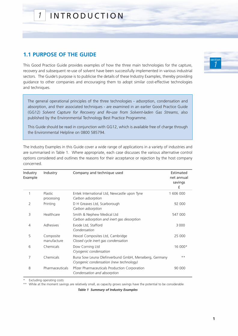
The Industry Examples in this Guide cover a wide range of applications in a variety of industries andare summarised in Table 1. Where appropriate, each case discusses the various alternative controloptions considered and outlines the reasons for their acceptance or rejection by the host companyconcerned.
Industry Industry Company and technique used Estimated Example net annual
savings£
1 Plastic Entek International Ltd, Newcastle upon Tyne 1 606 000processing Carbon adsorption
2 Printing D H Greaves Ltd, Scarborough 92 000Carbon adsorption
3 Healthcare Smith & Nephew Medical Ltd 547 000Carbon adsorption and inert gas desorption
4 Adhesives Evode Ltd, Stafford 3 000Condensation
5 Composite Hexcel Composites Ltd, Cambridge 25 000manufacture Closed cycle inert gas condensation
6 Chemicals Dow Corning Ltd 16 000*Cryogenic condensation
7 Chemicals Buna Sow Leuna Olefinverbund GmbH, Merseberg, Germany **Cryogenic condensation (new technology)
8 Pharmaceuticals Pfizer Pharmaceuticals Production Corporation 90 000Condensation and absorption
* Excluding operating costs** While at the moment savings are relatively small, as capacity grows savings have the potential to be considerable
Table 1 Summary of Industry Examples
1
I N T R O D U C T I O N1
section
1
The general operational principles of the three technologies - adsorption, condensation andabsorption, and their associated techniques - are examined in an earlier Good Practice Guide(GG12) Solvent Capture for Recovery and Re-use from Solvent-laden Gas Streams, alsopublished by the Environmental Technology Best Practice Programme.
This Guide should be read in conjunction with GG12, which is available free of charge throughthe Environmental Helpline on 0800 585794.
1.2 TARGET AUDIENCE
This Guide is intended for the site managers of all companies that use solvents. It is likely to beespecially relevant to companies in the following industrial sectors:
■ printing;
■ coating processes;
■ manufacture of coatings, varnishes, inks and adhesives;
■ chemical, fine chemical and pharmaceutical manufacture;
■ surface cleaning.
The Guide should be particularly useful where companies are considering fitting new abatementequipment to existing plant, upgrading existing equipment or installing new process plant.
1.3 WHY SOLVENT RECOVERY?
Increasingly, solvent-using companies are having to reduce their solvent emissions in order to meetcurrent and future environmental legislation. When reducing solvent consumption is not possible,eg through solvent management,1 then recovery and re-use can offer a return on capital investment.By capturing solvent emissions and re-using the recovered solvent, companies can save money andmeet their environmental obligations.
The recovery of solvent will:
■ reduce your solvent purchase cost and therefore increase your profitability;
■ reduce solvent emissions to the atmosphere;
■ eliminate the need for pollution abatement equipment by reducing solvent consumptionbelow the registration threshold for Integrated Pollution Control (IPC)/Local Air PollutionControl (LAPC);
■ reduce the cost of pollution abatement equipment by process optimisation, eg reducing thesize and thus cost of the equipment needed.
2
section
1
1 See also Good Practice Guide (GG13) Cost-effective Solvent Management, which is available free of charge through theEnvironmental Helpline on 0800 585794.
While the potential for solvent capture and recovery may be well known, the optimum recoverytechnology for a particular process application may not be immediately obvious. Relevantinformation on the alternatives is available from the Industry Examples that make up this Guide. Insome cases it may be necessary to approach the whole issue of solvent recovery from first principles,and to consider each of the following factors:
■ nature of the air stream;
■ properties of the solvents used;
■ process characteristics;
■ airflow characteristics;
■ potential for using the recovered solvent;
■ solvent costs.
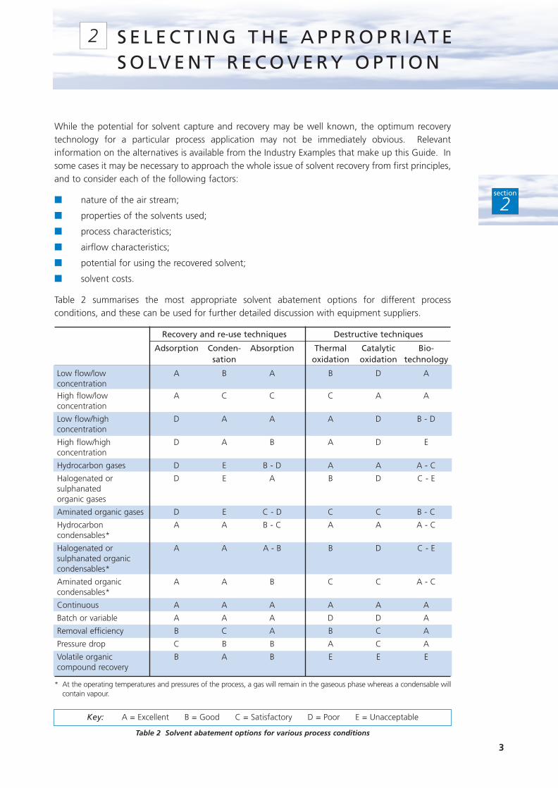
Table 2 summarises the most appropriate solvent abatement options for different processconditions, and these can be used for further detailed discussion with equipment suppliers.
Recovery and re-use techniques Destructive techniques
Adsorption Conden- Absorption Thermal Catalytic Bio-sation oxidation oxidation technology
Low flow/low A B A B D AconcentrationHigh flow/low A C C C A Aconcentration
Low flow/high D A A A D B - Dconcentration
High flow/high D A B A D Econcentration
Hydrocarbon gases D E B - D A A A - C
Halogenated or D E A B D C - Esulphanated organic gases
Aminated organic gases D E C - D C C B - C
Hydrocarbon A A B - C A A A - Ccondensables*
Halogenated or A A A - B B D C - Esulphanated organic condensables*
Aminated organic A A B C C A - Ccondensables*
Continuous A A A A A A
Batch or variable A A A D D A
Removal efficiency B C A B C A
Pressure drop C B B A C A
Volatile organic B A B E E Ecompound recovery
* At the operating temperatures and pressures of the process, a gas will remain in the gaseous phase whereas a condensable willcontain vapour.
Table 2 Solvent abatement options for various process conditions
3
section
2
S E L E C T I N G T H E A P P R O P R I AT ES O LV E N T R E C O V E R Y O P T I O N
2
Key: A = Excellent B = Good C = Satisfactory D = Poor E = Unacceptable

The following summaries, drawn from GG12, outline the main considerations for adsorption,condensation and absorption. This Guide does not cover destructive techniques, for moreinformation on these please contact the Environmental Helpline free of charge on 0800 585794.
2.1 ADSORPTION
■ Extensively used for solvent recovery, with granular activated carbon as the most commonadsorbent. Particularly practical for intermittent solvent sources.
■ Adsorption capacity increases with increasing molecular weight and boiling point of solvent,but decreases with increasing polarity. Activated carbon adsorption is impaired whenhumidity of gas stream exceeds 60%.
■ Desorption (recovery) can be carried out using steam, a hot inert gas such as nitrogen, orunder vacuum.
■ Continuous adsorption-desorption process systems can be either fixed beds that operate inalternate modes, or systems where the adsorbent is continuously conveyed between theadsorber and the desorber.
■ Adsorbent life is significantly reduced by contaminating particulates and by high boiling pointsolvents.
■ Using an inert gas rather than air allows the airflow rate to be reduced and solvent concentrationsto be increased without compromising safety. Reducing the airflow rate in this way will reduceoperating costs and improve the cost-effectiveness of solvent capture and re-use.
2.2 CONDENSATION
■ Coolant/refrigerant condensation is proven technology, traditionally used for preliminarysolvent recovery, eg prior to adsorption.
■ Conventional techniques are particularly suited to recovery of concentrated emissions of highvapour pressure solvents.
■ Cryogenic systems are less widely used, but can be used for recovery of all solvents,irrespective of vapour pressure.
■ Economic feasibility of condensation depends on the temperature reduction required foreffective recovery. Condensation temperatures well below 0°C can involve higher capital andoperating costs unless nitrogen is already used on-site.
■ Differential freezing points are likely to occur in the air stream because of the presence ofwater vapour and/or other components. Depending on the condensation temperature, thismay give rise to frozen material on the heat transfer surface and a subsequent reduction incondensation rate.
■ Using an inert gas rather than air allows the airflow rate to be reduced and solvent concentrationsto be increased without compromising safety. Reducing the airflow rate in this way will reduceoperating costs and improve the cost-effectiveness of solvent capture and re-use.
4
section
2
2.3 ABSORPTION
■ Feasible solvent recovery option provided solvent is readily soluble in either water or anorganic compound with a high boiling point.
■ Can take place in packed, plate or spray columns and requires little floor space.
■ Scrubbing liquids can be regenerated using either steam stripping (for organic liquids) ordistillation (aqueous liquids).
■ Degradation of scrubbing liquids may result from high desorption temperatures, chemicalreactions or impurities in the feed. This increases treatment/disposal costs and necessitatesspace for the appropriate equipment.
■ Using an inert gas rather than air allows the airflow rate to be reduced and solventconcentrations to be increased without compromising safety. Decreasing the airflow rate inthis way will reduce operating costs and improve the cost-effectiveness of solvent capture andre-use.
5
section
2

6
INDUSTRY EXAMPLES3
section
3
I n d u s t r y E x a m p l e 1A d s o r p t i o n R e d u c e s S o l v e n t E m i s s i o n s a t E n t e kI n t e r n a t i o n a l L t d
I n d u s t r y E x a m p l e 2A d s o r p t i o n I n c r e a s e s E f f i c i e n c y o f S o l v e n tC a p t u r e a t D H G r e a v e s L t d
I n d u s t r y E x a m p l e 3U s i n g A d s o r p t i o n t o R e c o v e r T H F f o r R e - u s e a t S m i t h & N e p h e w M e d i c a l L t d
I n d u s t r y E x a m p l e 4L o w - c o s t R e d u c t i o n i n E m i s s i o n s T h r o u g hC o n d e n s a t i o n a t E v o d e L t d
I n d u s t r y E x a m p l e 5C o n d e n s a t i o n R e d u c e s S o l v e n t C o n s u m p t i o n a tH e x c e l C o m p o s i t e s L t d
I n d u s t r y E x a m p l e 6C o n d e n s a t i o n R e d u c e s P r o c e s s E m i s s i o n s a tD o w C o r n i n g L t d
I n d u s t r y E x a m p l e 7C r y o g e n i c C o n d e n s a t i o n f o r S o l v e n t R e c o v e r ya t B u n a S o w L e u n a O l e f i n v e r b u n d G m b H
I n d u s t r y E x a m p l e 8S o l v e n t E m i s s i o n s R e d u c e d b y C o n d e n s a t i o na n d A b s o r p t i o n Te c h n i q u e s a t P f i z e rP h a r m a c e u t i c a l s P r o d u c t i o n C o r p o r a t i o n
Ad
so
rpti
on
Co
nd
en
sa
tio
nC
on
de
ns
ati
on
an
d a
bs
orp
tio
n
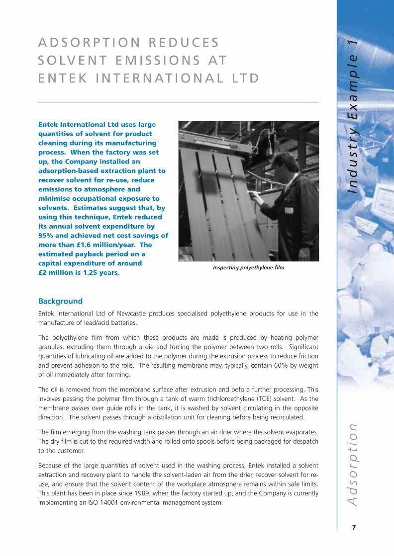
Entek International Ltd uses largequantities of solvent for productcleaning during its manufacturingprocess. When the factory was setup, the Company installed anadsorption-based extraction plant torecover solvent for re-use, reduceemissions to atmosphere andminimise occupational exposure tosolvents. Estimates suggest that, byusing this technique, Entek reducedits annual solvent expenditure by95% and achieved net cost savings ofmore than £1.6 million/year. Theestimated payback period on acapital expenditure of around £2 million is 1.25 years.
Background
Entek International Ltd of Newcastle produces specialised polyethylene products for use in themanufacture of lead/acid batteries.
The polyethylene film from which these products are made is produced by heating polymergranules, extruding them through a die and forcing the polymer between two rolls. Significantquantities of lubricating oil are added to the polymer during the extrusion process to reduce frictionand prevent adhesion to the rolls. The resulting membrane may, typically, contain 60% by weightof oil immediately after forming.
The oil is removed from the membrane surface after extrusion and before further processing. Thisinvolves passing the polymer film through a tank of warm trichloroethylene (TCE) solvent. As themembrane passes over guide rolls in the tank, it is washed by solvent circulating in the oppositedirection. The solvent passes through a distillation unit for cleaning before being recirculated.
The film emerging from the washing tank passes through an air drier where the solvent evaporates.The dry film is cut to the required width and rolled onto spools before being packaged for despatchto the customer.
Because of the large quantities of solvent used in the washing process, Entek installed a solventextraction and recovery plant to handle the solvent-laden air from the drier, recover solvent for re-use, and ensure that the solvent content of the workplace atmosphere remains within safe limits.This plant has been in place since 1989, when the factory started up, and the Company is currentlyimplementing an ISO 14001 environmental management system.
7
Ad
sorp
tio
nIn
du
stry
Ex
am
ple
1A D S O R P T I O N R E D U C E S S O LV E N T E M I S S I O N S AT E N T E K I N T E R N AT I O N A L LT D
Inspecting polyethylene film

The Solvent Recovery Process
Solvent extraction and recovery by adsorption is a batch process in which a solvent-laden gas streamis passed through a suitable adsorption bed to remove the solvents from the stream. After a periodof time, the bed becomes saturated with solvent, its adsorption efficiency falls, and it must be takenout of commission for a period of regeneration. It is normal to operate at least two adsorption bedsso that one is regenerating while the other is adsorbing.
Prior to 1989, several other companies in the US organisation to which Entek International belongshad already successfully used this adsorption technique in plants producing similar products. It wastherefore introduced to Entek as proven technology. The solvent-laden gas stream is extracted fromthe drier by large fans and is passed through activated carbon beds to remove the solvent (Fig 1).The plant has four such beds, each containing approximately ten tonnes of carbon. This ensuresthat at least two can be operated in adsorption mode at any one time, while the others are beingregenerated.
Fig 1 The solvent recovery process at Entek International Ltd
Carbon regeneration and solvent recovery is carried out as follows:
1 Steam is passed through the solvent-laden bed.
2 The resulting mixture of solvent and steam passes through a water-cooled condenser,producing cooled solvent and condensate.
3 The cooled solvent and condensate separate out in an adjacent decanter. The recoveredsolvent is pumped to a solvent storage tank. The water is returned to the cooling tower.
4 The condensate leaving the condenser is finally passed through a distillation column fittedwith a second condenser. This recovers the last of the solvent and ensures that emissions toatmosphere are, typically, less than five parts per million.
8
Ad
sorp
tio
nIn
du
stry
Ex
am
ple
1
Solventladen air
Steam
To main solvent
tank
Granular activated carbonadsorption beds x 4
Exhaust toatmosphere
Watercooled
condenser
Distillationcolumn
Watercooled
condenser
Solventstore
Water in
Water out
Water in
Water out
Water in
Water out
Decanter
FanAdsorption
Desorption
Cost Savings and Other Benefits
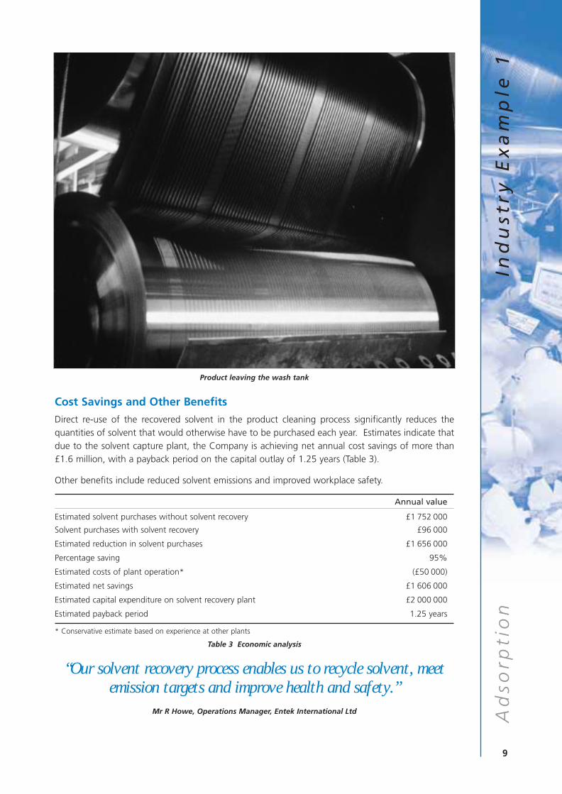
Direct re-use of the recovered solvent in the product cleaning process significantly reduces thequantities of solvent that would otherwise have to be purchased each year. Estimates indicate thatdue to the solvent capture plant, the Company is achieving net annual cost savings of more than£1.6 million, with a payback period on the capital outlay of 1.25 years (Table 3).
Other benefits include reduced solvent emissions and improved workplace safety.
Annual value
Estimated solvent purchases without solvent recovery £1 752 000
Solvent purchases with solvent recovery £96 000
Estimated reduction in solvent purchases £1 656 000
Percentage saving 95%
Estimated costs of plant operation* (£50 000)
Estimated net savings £1 606 000
Estimated capital expenditure on solvent recovery plant £2 000 000
Estimated payback period 1.25 years
* Conservative estimate based on experience at other plants
Table 3 Economic analysis
“Our solvent recovery process enables us to recycle solvent, meetemission targets and improve health and safety.”
Mr R Howe, Operations Manager, Entek International Ltd
9
Ad
sorp
tio
nIn
du
stry
Ex
am
ple
1
Product leaving the wash tank
A D S O R P T I O N I N C R E A S E SE F F I C I E N C Y O F S O LV E N T C A P T U R EAT D H G R E AV E S LT D
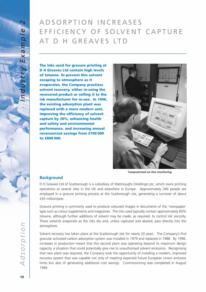
The inks used for gravure printing atD H Greaves Ltd contain high levelsof toluene. To prevent this solventescaping to atmosphere as itevaporates, the Company practisessolvent recovery, either re-using therecovered product or selling it to theink manufacturer for re-use. In 1996,the existing adsorption plant wasreplaced with a more modern unit,improving the efficiency of solventcapture by 20%, enhancing healthand safety and environmentalperformance, and increasing annualrevenue/cost savings from £700 000to £800 000.
Background
D H Greaves Ltd of Scarborough is a subsidiary of Watmoughs (Holdings) plc, which owns printingoperations at several sites in the UK and elsewhere in Europe. Approximately 340 people areemployed in a gravure printing process at the Scarborough site, generating a turnover of about £45 million/year.
Gravure printing is commonly used to produce coloured images in documents of the ‘newspaper’type such as colour supplements and magazines. The inks used typically contain approximately 60%toluene, although further additions of solvent may be made, as required, to control ink viscosity.These solvents evaporate as the inks dry and, unless captured and abated, pass directly into theatmosphere.
Solvent recovery has taken place at the Scarborough site for nearly 20 years. The Company’s firstgranular activated carbon adsorption system was installed in 1979 and replaced in 1988. By 1996,increases in production meant that this second plant was operating beyond its maximum designcapacity, a situation that could potentially give rise to unauthorised solvent emissions. Recognisingthat new plant was required, the Company took the opportunity of installing a modern, improvedrecovery system that was capable not only of meeting expected future European Union emissionlimits but also of generating additional cost savings. Commissioning was completed in August1996.
10
Ad
sorp
tio
nIn
du
stry
Ex
am
ple
2
Computerised on-line monitoring
The Solvent Recovery Process
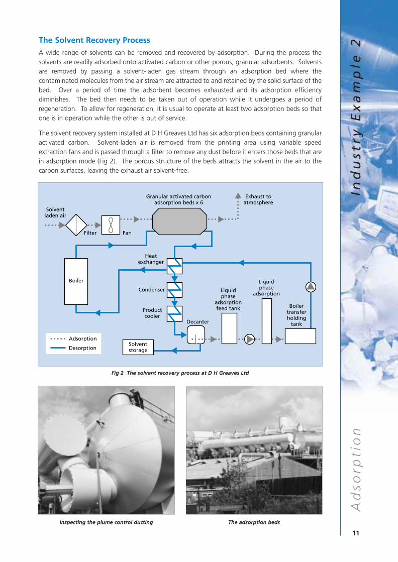
A wide range of solvents can be removed and recovered by adsorption. During the process thesolvents are readily adsorbed onto activated carbon or other porous, granular adsorbents. Solventsare removed by passing a solvent-laden gas stream through an adsorption bed where thecontaminated molecules from the air stream are attracted to and retained by the solid surface of thebed. Over a period of time the adsorbent becomes exhausted and its adsorption efficiencydiminishes. The bed then needs to be taken out of operation while it undergoes a period ofregeneration. To allow for regeneration, it is usual to operate at least two adsorption beds so thatone is in operation while the other is out of service.
The solvent recovery system installed at D H Greaves Ltd has six adsorption beds containing granularactivated carbon. Solvent-laden air is removed from the printing area using variable speedextraction fans and is passed through a filter to remove any dust before it enters those beds that arein adsorption mode (Fig 2). The porous structure of the beds attracts the solvent in the air to thecarbon surfaces, leaving the exhaust air solvent-free.
Fig 2 The solvent recovery process at D H Greaves Ltd
11
Ad
sorp
tio
nIn
du
stry
Ex
am
ple
2
Solventladen air
Granular activated carbonadsorption beds x 6
Exhaust toatmosphere
Boiler
Heatexchanger
Condenser
Productcooler
Solventstorage
Decanter
Liquidphase
adsorptionfeed tank
Liquidphase
adsorption
Boilertransferholding
tank
Filter Fan
Adsorption
Desorption
Inspecting the plume control ducting The adsorption beds
When an adsorption bed is saturated with solvent, it is automatically taken off-line and regenerated.This involves injecting steam into the top of each bed and passing it downwards through the bedto remove the solvent adhering to the carbon surfaces. The resulting steam/solvent mixture passesfirst to a condenser and then to a decanter, where the solvent and water condensate separate out.
The recovered solvent is then automatically transferred to a storage tank and is either re-used in theprocess as a ‘thinners’ material or sold to the ink manufacturer for re-use. The water condensate,however, still retains small amounts of solvent which must be removed before the water can bereturned to the hot well of the boiler. This is achieved using a liquid phase adsorber.
Before the regenerated bed can be brought back on-line, the carbon must be dried. This is achievedby blowing warm air through the carbon layers.
Because of improvements in process control procedures, the adsorption beds are now regeneratedwhen necessary rather than at regular intervals. This has reduced the quantities of steam requiredfor regeneration and the associated costs of boiler operation.
The solvent recovery plant has sufficient capacity during periods of peak demand to allow two bedsto be off-line awaiting service and regeneration at any one time.
The Company has encountered no significant problems over the last decade with the generaloperation of its solvent recovery plants. Granular activated carbon adsorption has proved to be veryreliable.
Cost Savings and Other Benefits
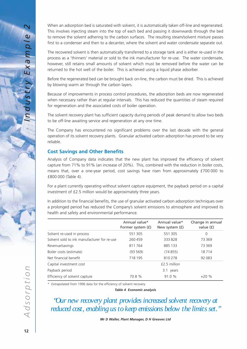
Analysis of Company data indicates that the new plant has improved the efficiency of solventcapture from 71% to 91% (an increase of 20%). This, combined with the reduction in boiler costs,means that, over a one-year period, cost savings have risen from approximately £700 000 to£800 000 (Table 4).
For a plant currently operating without solvent capture equipment, the payback period on a capitalinvestment of £2.5 million would be approximately three years.
In addition to the financial benefits, the use of granular activated carbon adsorption techniques overa prolonged period has reduced the Company’s solvent emissions to atmosphere and improved itshealth and safety and environmental performance.
Annual value* Annual value* Change in annualFormer system (£) New system (£) value (£)
Solvent re-used in process 551 305 551 305 0
Solvent sold to ink manufacturer for re-use 260 459 333 828 73 369
Revenue/savings 811 764 885 133 73 369
Boiler costs (estimate) (93 569) (74 855) 18 714
Net financial benefit 718 195 810 278 92 083
Capital investment cost £2.5 million
Payback period 3.1 years
Efficiency of solvent capture 70.8 % 91.0 % +20 %
* Extrapolated from 1996 data for the efficiency of solvent recovery
Table 4 Economic analysis
“Our new recovery plant provides increased solvent recovery atreduced cost, enabling us to keep emissions below the limits set.”
Mr D Waller, Plant Manager, D H Greaves Ltd
12
Ad
sorp
tio
nIn
du
stry
Ex
am
ple
2
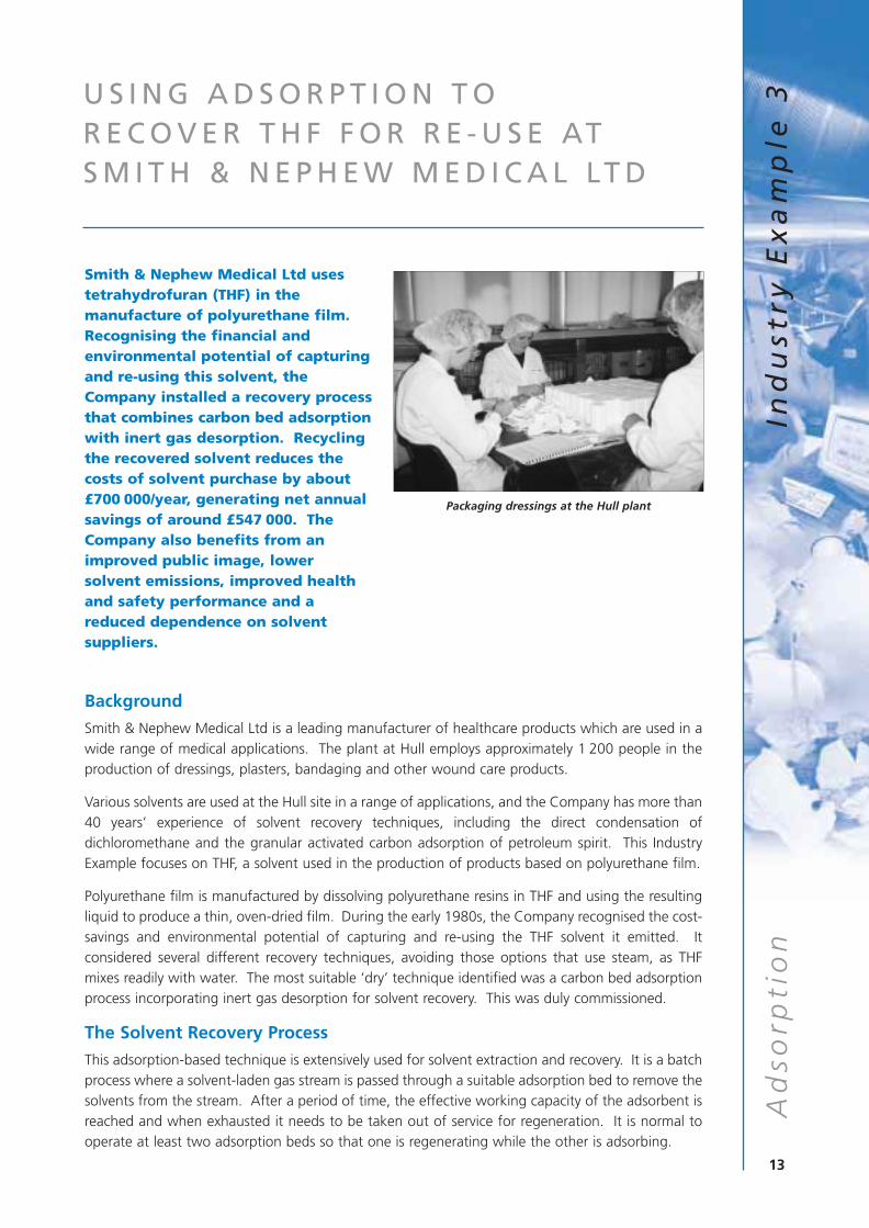
Smith & Nephew Medical Ltd usestetrahydrofuran (THF) in themanufacture of polyurethane film.Recognising the financial andenvironmental potential of capturingand re-using this solvent, theCompany installed a recovery processthat combines carbon bed adsorptionwith inert gas desorption. Recyclingthe recovered solvent reduces thecosts of solvent purchase by about£700 000/year, generating net annualsavings of around £547 000. TheCompany also benefits from animproved public image, lowersolvent emissions, improved healthand safety performance and areduced dependence on solventsuppliers.
Background
Smith & Nephew Medical Ltd is a leading manufacturer of healthcare products which are used in awide range of medical applications. The plant at Hull employs approximately 1 200 people in theproduction of dressings, plasters, bandaging and other wound care products.
Various solvents are used at the Hull site in a range of applications, and the Company has more than40 years’ experience of solvent recovery techniques, including the direct condensation ofdichloromethane and the granular activated carbon adsorption of petroleum spirit. This IndustryExample focuses on THF, a solvent used in the production of products based on polyurethane film.
Polyurethane film is manufactured by dissolving polyurethane resins in THF and using the resultingliquid to produce a thin, oven-dried film. During the early 1980s, the Company recognised the cost-savings and environmental potential of capturing and re-using the THF solvent it emitted. Itconsidered several different recovery techniques, avoiding those options that use steam, as THFmixes readily with water. The most suitable ‘dry’ technique identified was a carbon bed adsorptionprocess incorporating inert gas desorption for solvent recovery. This was duly commissioned.
The Solvent Recovery Process
This adsorption-based technique is extensively used for solvent extraction and recovery. It is a batchprocess where a solvent-laden gas stream is passed through a suitable adsorption bed to remove thesolvents from the stream. After a period of time, the effective working capacity of the adsorbent isreached and when exhausted it needs to be taken out of service for regeneration. It is normal tooperate at least two adsorption beds so that one is regenerating while the other is adsorbing.
13
Ad
sorp
tio
nIn
du
stry
Ex
am
ple
3U S I N G A D S O R P T I O N T O R E C O V E R T H F F O R R E - U S E AT S M I T H & N E P H E W M E D I C A L LT D
Packaging dressings at the Hull plant
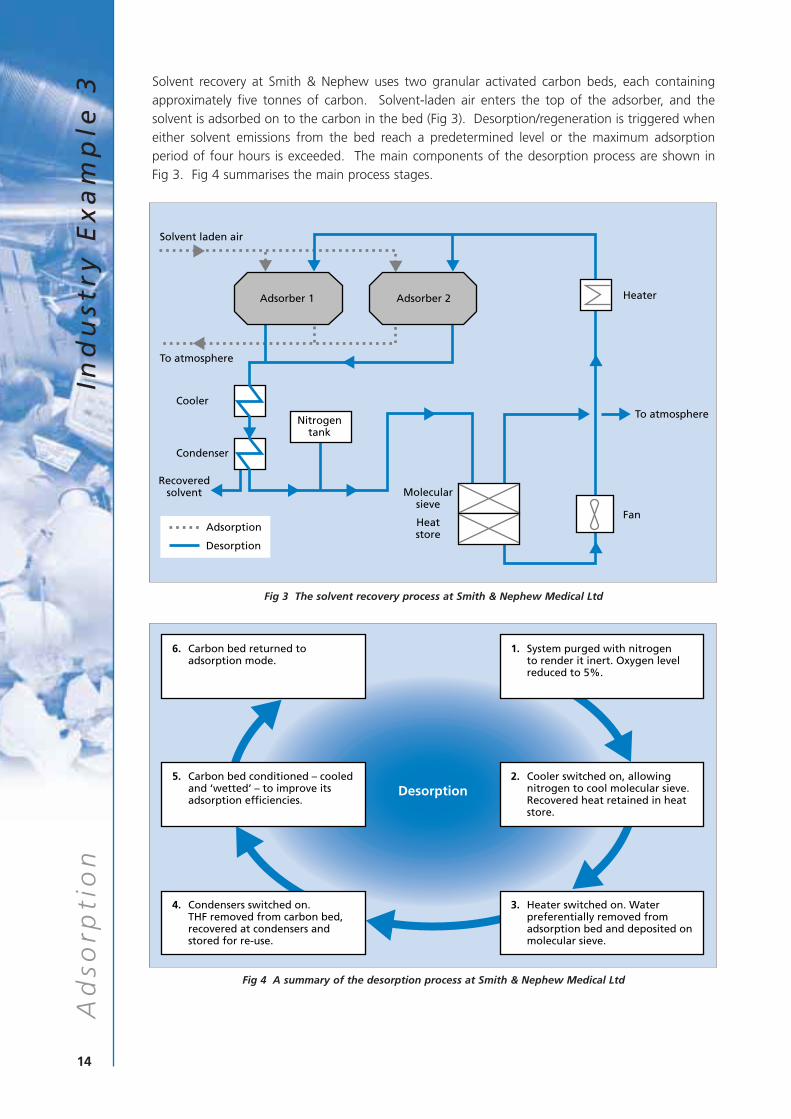
Solvent recovery at Smith & Nephew uses two granular activated carbon beds, each containingapproximately five tonnes of carbon. Solvent-laden air enters the top of the adsorber, and thesolvent is adsorbed on to the carbon in the bed (Fig 3). Desorption/regeneration is triggered wheneither solvent emissions from the bed reach a predetermined level or the maximum adsorptionperiod of four hours is exceeded. The main components of the desorption process are shown in Fig 3. Fig 4 summarises the main process stages.
Fig 3 The solvent recovery process at Smith & Nephew Medical Ltd
Fig 4 A summary of the desorption process at Smith & Nephew Medical Ltd
14
Ad
sorp
tio
nIn
du
stry
Ex
am
ple
3
Solvent laden air
To atmosphere
Condenser
Recoveredsolvent Molecular
sieve
Heatstore
CoolerTo atmosphere
Heater
Fan
Adsorber 2
Adsorption
Desorption
Nitrogentank
Adsorber 1
6. Carbon bed returned to adsorption mode.
1. System purged with nitrogento render it inert. Oxygen levelreduced to 5%.
2. Cooler switched on, allowingnitrogen to cool molecular sieve.Recovered heat retained in heatstore.
5. Carbon bed conditioned – cooledand ‘wetted’ – to improve itsadsorption efficiencies.
3. Heater switched on. Waterpreferentially removed fromadsorption bed and deposited on molecular sieve.
4. Condensers switched on. THF removed from carbon bed, recovered at condensers and stored for re-use.
Desorption
Cost Savings and Other Benefits
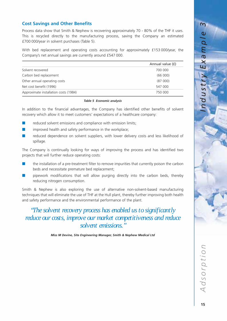
Process data show that Smith & Nephew is recovering approximately 70 - 80% of the THF it uses.This is recycled directly to the manufacturing process, saving the Company an estimated£700 000/year in solvent purchases (Table 5).
With bed replacement and operating costs accounting for approximately £153 000/year, theCompany’s net annual savings are currently around £547 000.
Annual value (£)
Solvent recovered 700 000
Carbon bed replacement (66 000)
Other annual operating costs (87 000)
Net cost benefit (1996) 547 000
Approximate installation costs (1984) 750 000
Table 5 Economic analysis
In addition to the financial advantages, the Company has identified other benefits of solventrecovery which allow it to meet customers’ expectations of a healthcare company:
■ reduced solvent emissions and compliance with emission limits;
■ improved health and safety performance in the workplace;
■ reduced dependence on solvent suppliers, with lower delivery costs and less likelihood ofspillage.
The Company is continually looking for ways of improving the process and has identified twoprojects that will further reduce operating costs:
■ the installation of a pre-treatment filter to remove impurities that currently poison the carbonbeds and necessitate premature bed replacement;
■ pipework modifications that will allow purging directly into the carbon beds, therebyreducing nitrogen consumption.
Smith & Nephew is also exploring the use of alternative non-solvent-based manufacturingtechniques that will eliminate the use of THF at the Hull plant, thereby further improving both healthand safety performance and the environmental performance of the plant.
“The solvent recovery process has enabled us to significantlyreduce our costs, improve our market competitiveness and reduce
solvent emissions.”Miss M Devine, Site Engineering Manager, Smith & Nephew Medical Ltd
15
Ad
sorp
tio
nIn
du
stry
Ex
am
ple
3
L O W - C O S T R E D U C T I O N I NE M I S S I O N S T H R O U G HC O N D E N S AT I O N AT E V O D E LT D
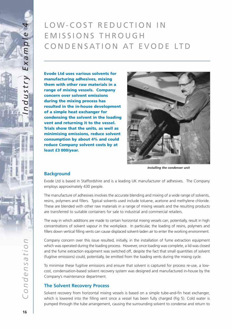
Evode Ltd uses various solvents formanufacturing adhesives, mixingthem with other raw materials in arange of mixing vessels. Companyconcern over solvent emissionsduring the mixing process hasresulted in the in-house developmentof a simple heat exchanger forcondensing the solvent in the loadingvent and returning it to the vessel.Trials show that the units, as well asminimising emissions, reduce solventconsumption by about 4% and couldreduce Company solvent costs by atleast £3 000/year.
Background
Evode Ltd is based in Staffordshire and is a leading UK manufacturer of adhesives. The Companyemploys approximately 430 people.
The manufacture of adhesives involves the accurate blending and mixing of a wide range of solvents,resins, polymers and fillers. Typical solvents used include toluene, acetone and methylene chloride.These are blended with other raw materials in a range of mixing vessels and the resulting productsare transferred to suitable containers for sale to industrial and commercial retailers.
The way in which additions are made to certain horizontal mixing vessels can, potentially, result in highconcentrations of solvent vapour in the workplace. In particular, the loading of resins, polymers andfillers down vertical filling vents can cause displaced solvent-laden air to enter the working environment.
Company concern over this issue resulted, initially, in the installation of fume extraction equipmentwhich was operated during the loading process. However, once loading was complete, a lid was closedand the fume extraction equipment was switched off, despite the fact that small quantities of solvent(fugitive emissions) could, potentially, be emitted from the loading vents during the mixing cycle.
To minimise these fugitive emissions and ensure that solvent is captured for process re-use, a low-cost, condensation-based solvent recovery system was designed and manufactured in-house by theCompany’s maintenance department.
The Solvent Recovery Process
Solvent recovery from horizontal mixing vessels is based on a simple tube-and-fin heat exchanger,which is lowered into the filling vent once a vessel has been fully charged (Fig 5). Cold water ispumped through the tube arrangement, causing the surrounding solvent to condense and return to
16
Co
nd
en
sati
on
Ind
ust
ry E
xa
mp
le 4
Installing the condenser unit
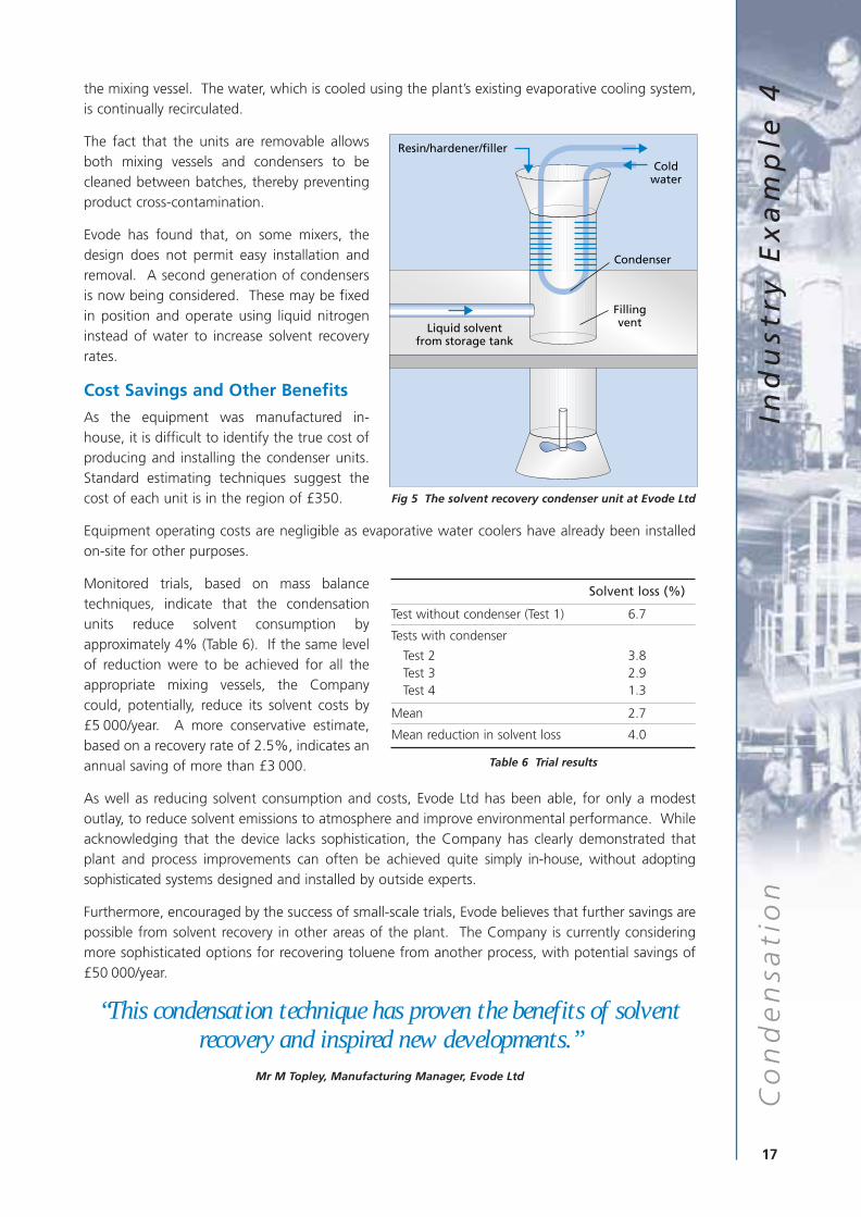
the mixing vessel. The water, which is cooled using the plant’s existing evaporative cooling system,is continually recirculated.
The fact that the units are removable allowsboth mixing vessels and condensers to becleaned between batches, thereby preventingproduct cross-contamination.
Evode has found that, on some mixers, thedesign does not permit easy installation andremoval. A second generation of condensersis now being considered. These may be fixedin position and operate using liquid nitrogeninstead of water to increase solvent recoveryrates.
Cost Savings and Other Benefits
As the equipment was manufactured in-house, it is difficult to identify the true cost ofproducing and installing the condenser units.Standard estimating techniques suggest thecost of each unit is in the region of £350.
Equipment operating costs are negligible as evaporative water coolers have already been installedon-site for other purposes.
Monitored trials, based on mass balancetechniques, indicate that the condensationunits reduce solvent consumption byapproximately 4% (Table 6). If the same levelof reduction were to be achieved for all theappropriate mixing vessels, the Companycould, potentially, reduce its solvent costs by£5 000/year. A more conservative estimate,based on a recovery rate of 2.5%, indicates anannual saving of more than £3 000.
As well as reducing solvent consumption and costs, Evode Ltd has been able, for only a modestoutlay, to reduce solvent emissions to atmosphere and improve environmental performance. Whileacknowledging that the device lacks sophistication, the Company has clearly demonstrated thatplant and process improvements can often be achieved quite simply in-house, without adoptingsophisticated systems designed and installed by outside experts.
Furthermore, encouraged by the success of small-scale trials, Evode believes that further savings arepossible from solvent recovery in other areas of the plant. The Company is currently consideringmore sophisticated options for recovering toluene from another process, with potential savings of£50 000/year.
“This condensation technique has proven the benefits of solventrecovery and inspired new developments.”
Mr M Topley, Manufacturing Manager, Evode Ltd
17
Co
nd
en
sati
on
Ind
ust
ry E
xa
mp
le 4
Resin/hardener/filler
Liquid solventfrom storage tank
Condenser
Coldwater
Fillingvent
Fig 5 The solvent recovery condenser unit at Evode Ltd
Solvent loss (%)
Test without condenser (Test 1) 6.7
Tests with condenser
Test 2 3.8Test 3 2.9Test 4 1.3
Mean 2.7
Mean reduction in solvent loss 4.0
Table 6 Trial results

C O N D E N S AT I O N R E D U C E S S O LV E N T C O N S U M P T I O N ATH E X C E L C O M P O S I T E S LT D
Hexcel Composites Ltd manufactureslightweight, high performancecomposite materials and structuresfor use in the commercial aerospace,space and defence, marine, sportsand leisure and general industrialmarkets. The Company is now usingbest available technology to recoverthe large quantities of solvent usedin the process, thereby reducingsolvent emissions by 94%, improvingCompany safety levels andenhancing its corporate image. Re-use of the recovered solvent forcleaning has reduced the cost ofsolvent purchases by approximately£50 000/year. Annual net costsavings are around £25 000.
Background
Hexcel Composites Ltd of Duxford, Cambridgeshire specialises in the manufacture of compositematerials that are subsequently used in the production of a range of products for aerospace,industrial and sports applications.
The manufacture of composite fabrics is a two-stage process. Epoxy or phenolic resins are firstcoated on to a siliconised release paper and oven-dried. The dried resins are then combined withcarbon, glass or kevlar fibres. The two main solvents used in the process are methylene chloride andmethyl ethyl ketone.
The main operation (textile coating and finishing process) is categorised as a Part B process underthe Environmental Protection Act 1990 and is authorised by the local authority.
In 1989 Hexcel installed a larger coating machine and drier to allow the production of wider rolls ofcomposite material. At the same time, anticipating forthcoming environmental legislation andgeneral pressures to improve environmental performance, the Company decided to incorporatesolvent recovery in the proposed development.
Initially, two techniques were believed to be potentially suitable for solvent recovery: adsorption,using granular activated carbon, and condensation. Consideration was also given to thermaloxidation, which destroys the waste solvent.
After a detailed review of the options, Hexcel decided to install a coating head and drier thatoperate in an inert atmosphere. Solvent recovery is achieved via a closed-cycle inert gascondensation process, using nitrogen as the carrier gas.
18
Co
nd
en
sati
on
Ind
ust
ry E
xa
mp
le 5
Discharging recovered solvent
The choice of solvent recovery technique was influenced by several factors:
■ the reduced risk of explosion associated with significantly reducing oxygen levels in thecoating process;
■ the technique’s flexibility, allowing it to be used with a range of different solvents;
■ concern over the thermal oxidation of chlorinated solvents;
■ the presence of ketones in the recovered solvents (granular activated carbon adsorption is notgenerally regarded as suitable in these circumstances);
■ the higher cost of adsorption for the volumes of gas involved.
The Solvent Recovery Process
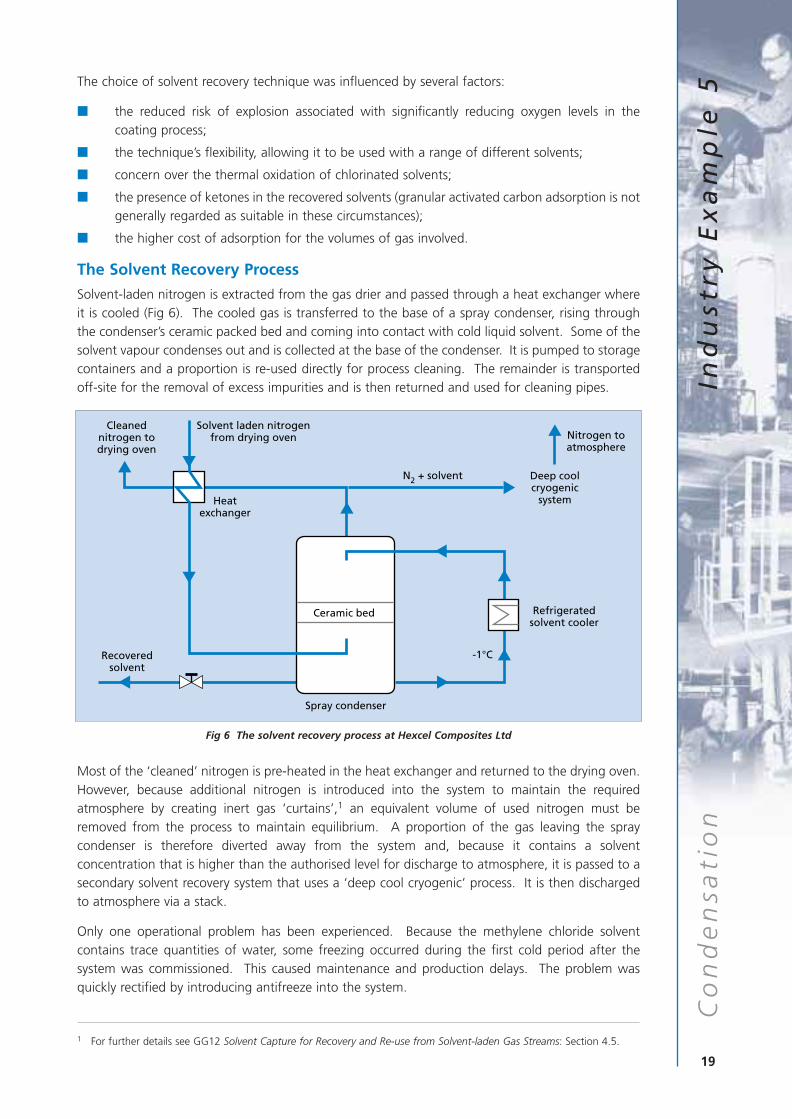
Solvent-laden nitrogen is extracted from the gas drier and passed through a heat exchanger whereit is cooled (Fig 6). The cooled gas is transferred to the base of a spray condenser, rising throughthe condenser’s ceramic packed bed and coming into contact with cold liquid solvent. Some of thesolvent vapour condenses out and is collected at the base of the condenser. It is pumped to storagecontainers and a proportion is re-used directly for process cleaning. The remainder is transportedoff-site for the removal of excess impurities and is then returned and used for cleaning pipes.
Most of the ‘cleaned’ nitrogen is pre-heated in the heat exchanger and returned to the drying oven.However, because additional nitrogen is introduced into the system to maintain the requiredatmosphere by creating inert gas ‘curtains’,1 an equivalent volume of used nitrogen must beremoved from the process to maintain equilibrium. A proportion of the gas leaving the spraycondenser is therefore diverted away from the system and, because it contains a solventconcentration that is higher than the authorised level for discharge to atmosphere, it is passed to asecondary solvent recovery system that uses a ‘deep cool cryogenic’ process. It is then dischargedto atmosphere via a stack.
Only one operational problem has been experienced. Because the methylene chloride solventcontains trace quantities of water, some freezing occurred during the first cold period after thesystem was commissioned. This caused maintenance and production delays. The problem wasquickly rectified by introducing antifreeze into the system.
19
Co
nd
en
sati
on
Ind
ust
ry E
xa
mp
le 5
Deep coolcryogenic
system
Nitrogen toatmosphere
Solvent laden nitrogen from drying oven
Cleanednitrogen todrying oven
Heatexchanger
N2 + solvent
Recoveredsolvent
Spray condenser
Ceramic bed
-1°C
Refrigeratedsolvent cooler
Fig 6 The solvent recovery process at Hexcel Composites Ltd
1 For further details see GG12 Solvent Capture for Recovery and Re-use from Solvent-laden Gas Streams: Section 4.5.
Cost Savings and Other Benefits
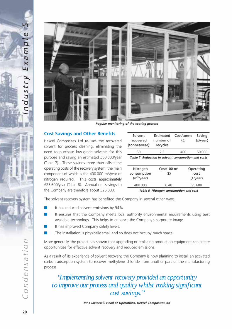
Hexcel Composites Ltd re-uses the recoveredsolvent for process cleaning, eliminating theneed to purchase low-grade solvents for thispurpose and saving an estimated £50 000/year(Table 7). These savings more than offset theoperating costs of the recovery system, the maincomponent of which is the 400 000 m3/year ofnitrogen required. This costs approximately£25 600/year (Table 8). Annual net savings tothe Company are therefore about £25 000.
The solvent recovery system has benefited the Company in several other ways:
■ It has reduced solvent emissions by 94%.
■ It ensures that the Company meets local authority environmental requirements using bestavailable technology. This helps to enhance the Company’s corporate image.
■ It has improved Company safety levels.
■ The installation is physically small and so does not occupy much space.
More generally, the project has shown that upgrading or replacing production equipment can createopportunities for effective solvent recovery and reduced emissions.
As a result of its experience of solvent recovery, the Company is now planning to install an activatedcarbon adsorption system to recover methylene chloride from another part of the manufacturingprocess.
“Implementing solvent recovery provided an opportunity to improve our process and quality whilst making significant
cost savings.”Mr J Tattersall, Head of Operations, Hexcel Composites Ltd
20
Co
nd
en
sati
on
Ind
ust
ry E
xa
mp
le 5
Solvent Estimated Cost/tonne Savingrecovered number of (£) (£/year)
(tonnes/year) recycles
50 2.5 400 50 000
Table 7 Reduction in solvent consumption and costs
Nitrogen Cost/100 m3 Operatingconsumption (£) cost
(m3/year) (£/year)
400 000 6.40 25 600
Table 8 Nitrogen consumption and cost
Regular monitoring of the coating process

Dow Corning Ltd uses large quantities of methyl chloride in the production ofspeciality chemicals. The Company has practised solvent recovery and re-use forseveral years using condensation techniques. It has now added a cryogenicprocess to the plant to increase levels of solvent recovery, thereby reducingprocess emissions to levels that are considered insignificant. Althoughenvironmental improvement rather than cost savings was the main objective,the Company has reduced its solvent purchases by about 40 tonnes/year. Theassociated cost saving is about £16 000/year.
Background
Dow Corning is a manufacturer of speciality chemicals, producing silicon-based products mainly forindustrial and consumer applications. The Company is based at Barry in South Wales and employsapproximately 550 people.
The manufacture of silicon products at the Barry site incorporates two fluidised bed reactions thatuse methyl chloride as the primary reactant with silicon powder. The resulting vapour is a mixture ofchlorosilanes and unreacted methyl chloride. These two components are separated in a distillationsystem, with the methyl chloride entering a recovery unit and being recycled for re-use in the samereaction vessels. The process is authorised as a Part A process under the Environmental ProtectionAct 1990 and is regulated by the Environment Agency.
The Solvent Recovery Process
Methyl chloride has been recovered from theprocess for a number of years using a system ofwater-cooled condensers and compressors, withthe vapour being compressed to allowcondensation within the chilled condensers. In1995, Dow Corning identified opportunities forrecovering increased quantities of methylchloride, thereby reducing process emissions stillfurther and providing additional economicbenefits. A cryogenic recovery process usingliquid nitrogen was therefore added to themethyl chloride recovery plant (Fig 7).
21
Co
nd
en
sati
on
Ind
ust
ry E
xa
mp
le 6C O N D E N S AT I O N R E D U C E S P R O C E S S
E M I S S I O N S AT D O W C O R N I N G LT D
Fluidisedbed
reactor
Productdistillation
Methylchloriderecovery
Cryogenicrecovery
Silicon
Methylchloride
Methylchlorosilaneproduct
Finalvent
Adsorption
Desorption
Fig 7 Solvent recovery at Dow Corning Ltd
Inspecting the pipework Inspecting system pressure
Cryogenic recovery was chosen for several reasons:
■ methyl chloride has a low boiling point (-23.7°C);
■ nitrogen bulk storage and pipework was already available on site;
■ a nitrogen vaporiser could readily be incorporated into the recovery system.
Although much of the equipment for the cryogenic recovery system was already available on site,the capital investment required was still significant at approximately £10 000/tonne of additionalsolvent recovered.
Cost Savings and Other Benefits
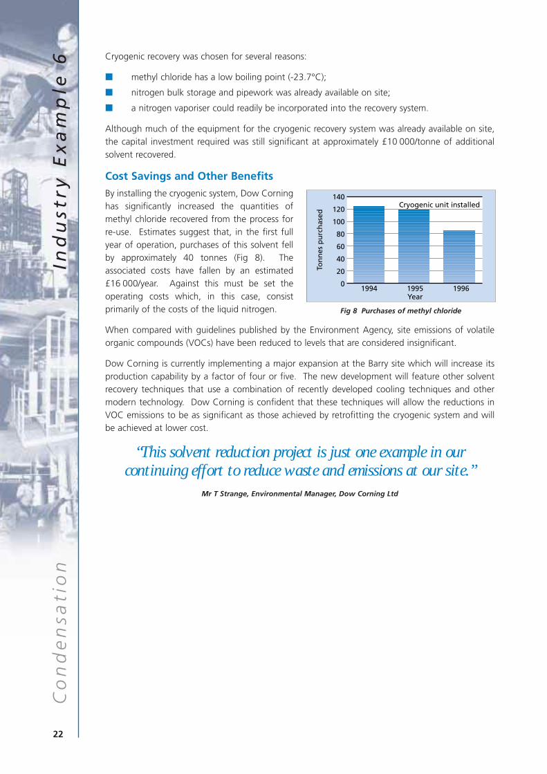
By installing the cryogenic system, Dow Corninghas significantly increased the quantities ofmethyl chloride recovered from the process forre-use. Estimates suggest that, in the first fullyear of operation, purchases of this solvent fellby approximately 40 tonnes (Fig 8). Theassociated costs have fallen by an estimated£16 000/year. Against this must be set theoperating costs which, in this case, consistprimarily of the costs of the liquid nitrogen.
When compared with guidelines published by the Environment Agency, site emissions of volatileorganic compounds (VOCs) have been reduced to levels that are considered insignificant.
Dow Corning is currently implementing a major expansion at the Barry site which will increase itsproduction capability by a factor of four or five. The new development will feature other solventrecovery techniques that use a combination of recently developed cooling techniques and othermodern technology. Dow Corning is confident that these techniques will allow the reductions inVOC emissions to be as significant as those achieved by retrofitting the cryogenic system and willbe achieved at lower cost.
“This solvent reduction project is just one example in ourcontinuing effort to reduce waste and emissions at our site.”
Mr T Strange, Environmental Manager, Dow Corning Ltd
22
Co
nd
en
sati
on
Ind
ust
ry E
xa
mp
le 6
140
120
100
80
60
40
20
01994 1995
Year1996
Cryogenic unit installed
Ton
nes
pu
rch
ased
Fig 8 Purchases of methyl chloride
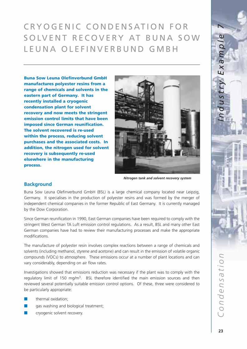
Buna Sow Leuna Olefinverbund GmbHmanufactures polyester resins from arange of chemicals and solvents in theeastern part of Germany. It hasrecently installed a cryogeniccondensation plant for solventrecovery and now meets the stringentemission control limits that have beenimposed since German reunification.The solvent recovered is re-usedwithin the process, reducing solventpurchases and the associated costs. Inaddition, the nitrogen used for solventrecovery is subsequently re-usedelsewhere in the manufacturingprocess.
Background
Buna Sow Leuna Olefinverbund GmbH (BSL) is a large chemical company located near Leipzig,Germany. It specialises in the production of polyester resins and was formed by the merger ofindependent chemical companies in the former Republic of East Germany. It is currently managedby the Dow Corporation.
Since German reunification in 1990, East German companies have been required to comply with thestringent West German TA Luft emission control regulations. As a result, BSL and many other EastGerman companies have had to review their manufacturing processes and make the appropriatemodifications.
The manufacture of polyester resin involves complex reactions between a range of chemicals andsolvents (including methanol, styrene and acetone) and can result in the emission of volatile organiccompounds (VOCs) to atmosphere. These emissions occur at a number of plant locations and canvary considerably, depending on air flow rates.
Investigations showed that emissions reduction was necessary if the plant was to comply with theregulatory limit of 150 mg/m3. BSL therefore identified the main emission sources and thenreviewed several potentially suitable emission control options. Of these, three were considered tobe particularly appropriate:
■ thermal oxidation;
■ gas washing and biological treatment;
■ cryogenic solvent recovery.
23
Co
nd
en
sati
on
Ind
ust
ry E
xa
mp
le 7C R Y O G E N I C C O N D E N S AT I O N F O R
S O LV E N T R E C O V E R Y AT B U N A S O WL E U N A O L E F I N V E R B U N D G M B H
Nitrogen tank and solvent recovery system
Detailed cost estimates for thermal oxidation indicated that installing and commissioning suitableequipment would be expensive, eg the pipeline carrying waste gases to a centralised thermaloxidation unit would require significant modification to ensure its successful integration withexisting systems. Not only would total costs be four to five times the cost of an appropriatecryogenic unit, but the Company was concerned about additional operating costs and possible‘secondary pollution’ from the combustion of off-gases.
Biological treatment techniques are becoming more widely used for the control of VOC emissions.However, in this case, such techniques were thought to be inappropriate because of the differentdecomposition rates of methanol, acetone and styrene. Trials also generated unpleasant odours,and these were viewed as a potential problem for residents in the immediate vicinity.
Cryogenic recovery techniques were believed to be the most effective, not only reducing emissionsbut providing BSL with an opportunity for increasing cost savings by re-using the recovered solvent.Consequently, following successful trials, a cryogenic condensation plant was commissioned inDecember 1996.
The Solvent Recovery Process
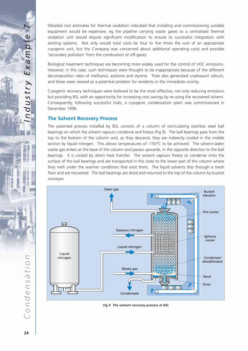
The patented process installed by BSL consists of a column of recirculating stainless steel ballbearings on which the solvent vapours condense and freeze (Fig 9). The ball bearings pass from thetop to the bottom of the column and, as they descend, they are indirectly cooled in the middlesection by liquid nitrogen. This allows temperatures of -150°C to be achieved. The solvent-ladenwaste gas enters at the base of the column and passes upwards, in the opposite direction to the ballbearings. It is cooled by direct heat transfer. The solvent vapours freeze or condense onto thesurface of the ball bearings and are transported in this state to the lower part of the column wherethey melt under the warmer conditions that exist there. The liquid solvents drip through a meshfloor and are recovered. The ball bearings are dried and returned to the top of the column by bucketconveyor.
Fig 9 The solvent recovery process at BSL
24
Co
nd
en
sati
on
Ind
ust
ry E
xa
mp
le 7
Liquidnitrogen
Waste gas
Condensate
Bucketelevator
Pre-cooler
Spherescooler
Condenser/desublimator
Sieve
Drier
Liquid nitrogen
Gaseous nitrogen
Clean gas
One major advantage of this process over other cryogenic techniques is the fact that the frozensolvent does not cause excessive pressure drops or blockages. Furthermore, the nitrogen used forcooling is used directly in the manufacturing process.
Because of the solvents used in this particular application and the high temperature of the wastegas, it is theoretically possible for the styrene to polymerise onto the surface of the cold ballbearings. This could give rise to a build-up of static charge on the spheres, creating the conditionsfor a potential explosion. The plant has therefore been fully earthed, and a device for monitoringthe conductivity of the spheres has been developed and installed as a safeguard, to ensurepolymerisation does not occur. For applications where polymerisation could not occur, modificationsof this type would not be necessary.
Extensive trials were conducted during plant commissioning to establish a correlation between thetemperature and solvent concentration of exit gases. By writing a suitable algorithm, BSL is nowable to monitor solvent concentrations in process emissions simply by recording the temperature.Such a technique is approved by the regulatory authority and provides a low-cost, indicative meansof continuously monitoring process emissions.
Cost Savings and Other Benefits
The benefits of installing this continuous cryogenic solvent recovery process have been considerable.They include:
■ emissions are now within regulatory limits;
■ solvents are recovered for re-use, reducing solvent purchases and the associated costs;
■ there is no secondary pollution.
The double use of nitrogen, with the solvent recovery unit acting as a first-stage vaporiser, was alsoa significant component of the project’s economic justification.
“This new technology enables us to meet higher emission targets at negligible cost.”
Herr D Riecke, Plant Manager, Buna Sow Leuna Olefinverbund GmbH
25
Co
nd
en
sati
on
Ind
ust
ry E
xa
mp
le 7
S O LV E N T E M I S S I O N S R E D U C E D B YC O N D E N S AT I O N A N D A B S O R P T I O NT E C H N I Q U E S AT P F I Z E RP H A R M A C E U T I C A L S P R O D U C T I O NC O R P O R AT I O N
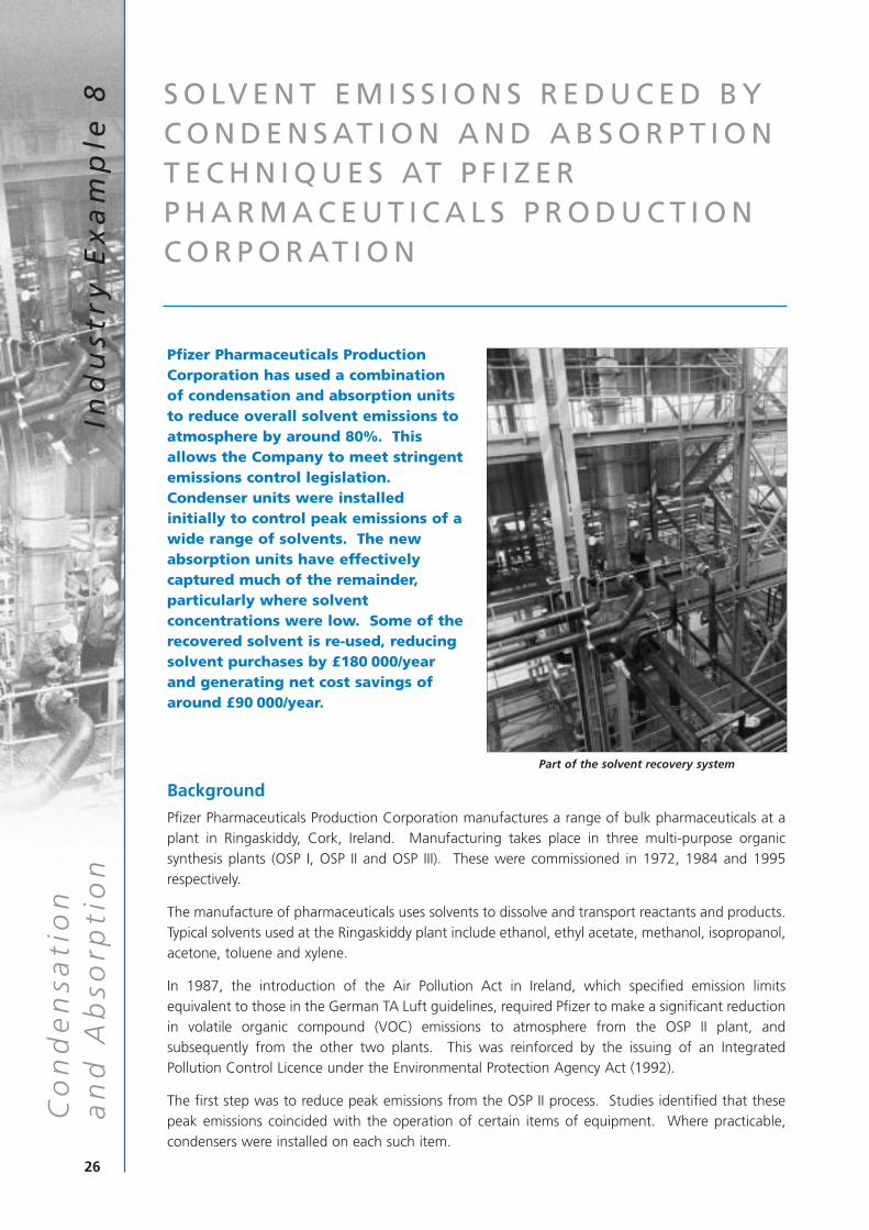
Pfizer Pharmaceuticals ProductionCorporation has used a combinationof condensation and absorption unitsto reduce overall solvent emissions toatmosphere by around 80%. Thisallows the Company to meet stringentemissions control legislation.Condenser units were installedinitially to control peak emissions of awide range of solvents. The newabsorption units have effectivelycaptured much of the remainder,particularly where solventconcentrations were low. Some of therecovered solvent is re-used, reducingsolvent purchases by £180 000/yearand generating net cost savings ofaround £90 000/year.
Background
Pfizer Pharmaceuticals Production Corporation manufactures a range of bulk pharmaceuticals at aplant in Ringaskiddy, Cork, Ireland. Manufacturing takes place in three multi-purpose organicsynthesis plants (OSP I, OSP II and OSP III). These were commissioned in 1972, 1984 and 1995respectively.
The manufacture of pharmaceuticals uses solvents to dissolve and transport reactants and products.Typical solvents used at the Ringaskiddy plant include ethanol, ethyl acetate, methanol, isopropanol,acetone, toluene and xylene.
In 1987, the introduction of the Air Pollution Act in Ireland, which specified emission limitsequivalent to those in the German TA Luft guidelines, required Pfizer to make a significant reductionin volatile organic compound (VOC) emissions to atmosphere from the OSP II plant, andsubsequently from the other two plants. This was reinforced by the issuing of an IntegratedPollution Control Licence under the Environmental Protection Agency Act (1992).
The first step was to reduce peak emissions from the OSP II process. Studies identified that thesepeak emissions coincided with the operation of certain items of equipment. Where practicable,condensers were installed on each such item.
26
an
d A
bso
rpti
on
Ind
ust
ry E
xa
mp
le 8
Co
nd
en
sati
on
Part of the solvent recovery system
However, it was not feasible to install condensers in all vents as, in many cases, the solventconcentrations involved were too low for effective capture. The Company therefore reviewed threeother techniques for reducing the baseline solvent concentrations to below the authorised limit:
■ thermal oxidation;
■ adsorption;
■ absorption.
Thermal oxidation is suitable for applications such as this where the waste stream may containvarious different solvents. It was rejected in this instance because of the potential presence of ahalogenated solvent which would have required a more expensive flue gas control system to ensurethat emissions remained within recognised limits.
Adsorption is potentially the most widely used recovery technique for general applications, andeither adsorption or absorption could have been used by Pfizer.
The Company chose to add an absorption unit to the existing solvent recovery system for severalreasons:
■ it is more effective in situations where there are solvent mixtures and fluctuating solventloads;
■ it is able to cope with high solvent concentrations;
■ it operates as a continuous process: this ensures that the solvent-laden air is always in contactwith regenerated absorbent, maximising VOC removal.
The Solvent Recovery Process
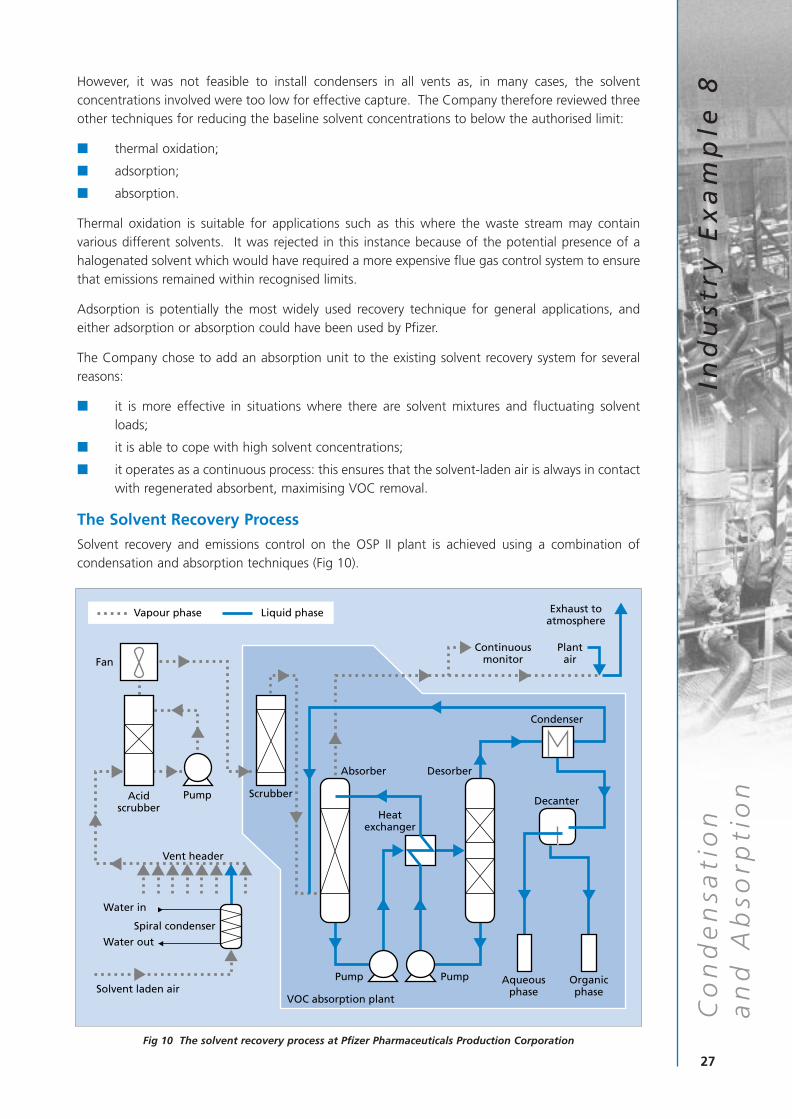
Solvent recovery and emissions control on the OSP II plant is achieved using a combination ofcondensation and absorption techniques (Fig 10).
Fig 10 The solvent recovery process at Pfizer Pharmaceuticals Production Corporation
27
Co
nd
en
sati
on
Ind
ust
ry E
xa
mp
le 8
an
d A
bso
rpti
onAcid
scrubberScrubber
Fan
Vent header
Spiral condenser
Solvent laden air
Water in
Water out
Absorber Desorber
Heatexchanger
Aqueousphase
Organicphase
VOC absorption plant
Decanter
Condenser
Exhaust toatmosphere
Plant air
Continuousmonitor
Pump
Pump Pump
Vapour phase Liquid phase
Condensation
Condensation techniques are widely used for solvent recovery. They may be based on water-cooledheat exchangers or refrigerants and are typically used to control peak emissions. In many cases, atwo-stage condensation system is used. This consists of a primary condenser serviced with coolingwater and a secondary condenser serviced with a low-temperature coolant.
In one example, installing a spiral condenser to limit peak emissions reduced the solvent stream tobetween 60% and 75% of its unabated level.
The solvents collected are re-used in the primary manufacturing processes.
Absorption
Waste process air is fed upwards through an absorption column where it is washed by a liquidabsorbent, polyethylene glycol dibutyl ether, which flows down through the column. This removessolvent from the air. The mixture of solvent and absorbent is collected at the base of the columnand pumped to a desorption column, where the solvents are removed by steam stripping. Thepurified absorbent accumulates at the base of the desorption column and is returned, via a heatexchanger and cooler, to the top of the absorption column. The steam/solvent mixture is removed,condensed and the two components separated out. However, the solvent component generallyconsists of a complex mixture of solvents that is unsuitable for recycling. Depending on miscibility,it is either disposed of in a suitably designed thermal oxidation unit or via appropriate treatmentsystems.
28
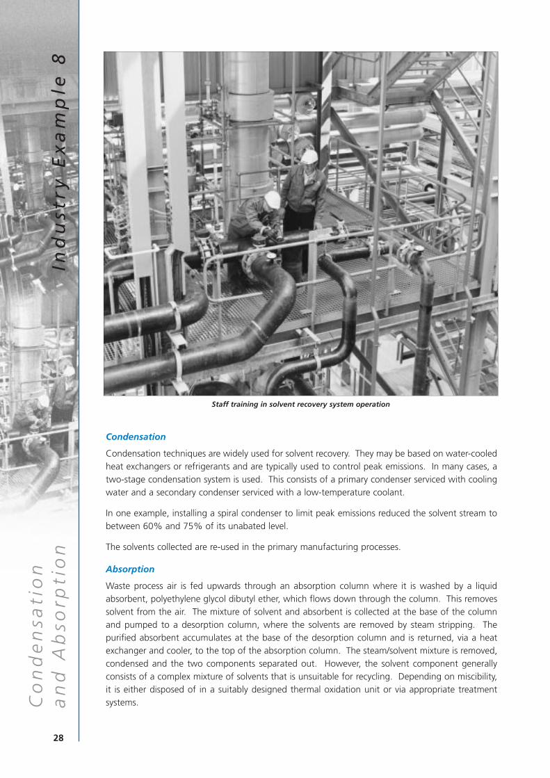
Staff training in solvent recovery system operation
an
d A
bso
rpti
on
Ind
ust
ry E
xa
mp
le 8
Co
nd
en
sati
on
The OSP II absorption recovery system cost approximately £1.2 million to install in 1993.
The effectiveness of the solvent recovery techniques employed has encouraged Pfizer to installsimilar emissions control equipment on the other two OSP plants (OSP I and OSP III) and at a newproduction facility in the USA.
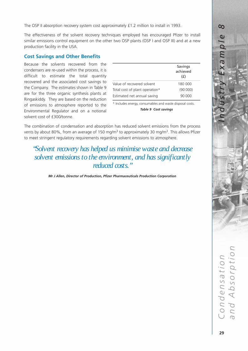
Cost Savings and Other Benefits
Because the solvents recovered from thecondensers are re-used within the process, it isdifficult to estimate the total quantityrecovered and the associated cost savings tothe Company. The estimates shown in Table 9are for the three organic synthesis plants atRingaskiddy. They are based on the reductionof emissions to atmosphere reported to theEnvironmental Regulator and on a notionalsolvent cost of £300/tonne.
The combination of condensation and absorption has reduced solvent emissions from the processvents by about 80%, from an average of 150 mg/m3 to approximately 30 mg/m3. This allows Pfizerto meet stringent regulatory requirements regarding solvent emissions to atmosphere.
“Solvent recovery has helped us minimise waste and decreasesolvent emissions to the environment, and has significantly
reduced costs.”Mr J Allen, Director of Production, Pfizer Pharmaceuticals Production Corporation
29
Savings achieved
(£)
Value of recovered solvent 180 000
Total cost of plant operation* (90 000)
Estimated net annual saving 90 000
* Includes energy, consumables and waste disposal costs.
Table 9 Cost savings
Co
nd
en
sati
on
Ind
ust
ry E
xa
mp
le 8
an
d A
bso
rpti
on
This Good Practice Guide has shown how eight companies in a range of industrial sectors havesuccessfully installed solvent recovery equipment, thereby reducing both their annual expenditure onsolvent purchases and solvent emissions to atmosphere.
The techniques applied vary. Three of the companies have used carbon adsorption techniques. Theremainder have opted for either conventional or cryogenic condensation. One firm has shown thatit is possible to combine technologies by using both condensation and absorption to meet itsemissions control objectives.
The Industry Examples clearly demonstrate that cost-effective solvent recovery can be achieved ondifferent scales and, in some circumstances, for a limited capital outlay. They also show that recoverycan be effective irrespective of the variety of solvents used and the quantities and concentrations ofthe emissions involved. The examples clearly indicate that the capture and re-use of solvents offersignificant cost and environmental benefits.
If, after reading this Good Practice Guide, you would like help with specific queries regarding solventcapture and re-use, or any environmental problem, please contact the Environmental Helpline on0800 585794. The Helpline can provide you with:
■ general information on solvent minimisation;
■ Environmental Technology Best Practice Programme literature on solvent management andgood housekeeping measures;
■ details of waste exchange and solvent recovery companies.
30
section
4
C O N C L U S I O N A N D A C T I O N P L A N4
ACTION PLAN
If you need to reduce your company’s VOC emissions cost effectively, you may benefitfrom answering the following questions:
Have I investigated all possible ways of minimising solvent use?
Could I re-use solvent directly in a process?
Could I re-use solvent for some other operation, eg cleaning?
Have I investigated waste exchange companies?
Have I consulted solvent recovery companies?
Can I make solvent recovery more economic by reducing airflows?
Can I make solvent recovery more economic by increasing solvent concentrations,subject to safety requirements?
Should I change to single solvent operation to make recovery more attractive?
Could newer solvent recovery techniques offer improved economics?
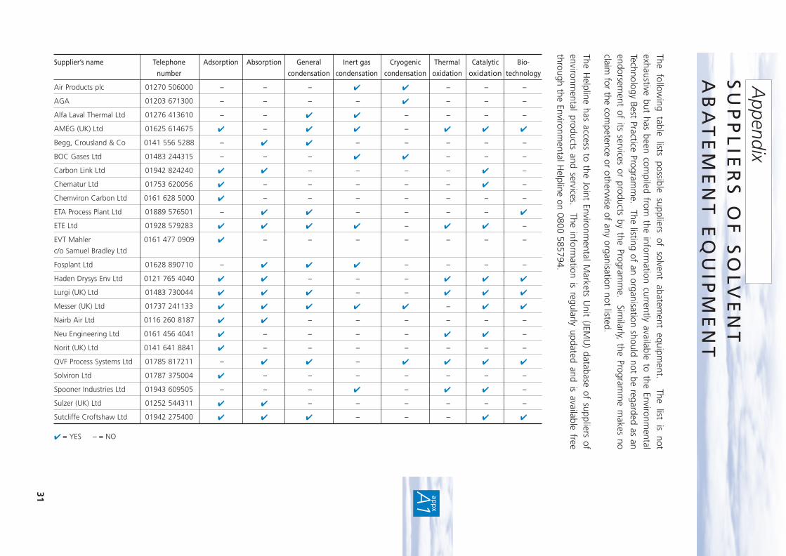
The following table lists possible suppliers of solvent abatem
ent equipment. The list is not
exhaustive but has been compiled from
the information currently available to the Environm
entalTechnology Best Practice Program
me. The listing of an organisation should not be regarded as an
endorsement of its services or products by the Program
me. Sim
ilarly, the Programm
e makes no
claim for the com
petence or otherwise of any organisation not listed.
The Helpline has access to the Joint Environm
ental Markets U
nit (JEMU
) database of suppliers ofenvironm
ental products and services. The information is regularly updated and is available free
through the Environmental H
elpline on 0800 585794.
31 app
x
A1
SU
PP
LIE
RS
OF
SO
LV
EN
TA
BA
TE
ME
NT
EQ
UIP
ME
NT
Appendix
Supplier’s name Telephone Adsorption Absorption General Inert gas Cryogenic Thermal Catalytic Bio-
number condensation condensation condensation oxidation oxidation technology
Air Products plc 01270 506000 – – – ✔ ✔ – – –
AGA 01203 671300 – – – – ✔ – – –
Alfa Laval Thermal Ltd 01276 413610 – – ✔ ✔ – – – –
AMEG (UK) Ltd 01625 614675 ✔ – ✔ ✔ – ✔ ✔ ✔
Begg, Crousland & Co 0141 556 5288 – ✔ ✔ – – – – –
BOC Gases Ltd 01483 244315 – – – ✔ ✔ – – –
Carbon Link Ltd 01942 824240 ✔ ✔ – – – – ✔ –
Chematur Ltd 01753 620056 ✔ – – – – – ✔ –
Chemviron Carbon Ltd 0161 628 5000 ✔ – – – – – – –
ETA Process Plant Ltd 01889 576501 – ✔ ✔ – – – – ✔
ETE Ltd 01928 579283 ✔ ✔ ✔ ✔ – ✔ ✔ –
EVT Mahler 0161 477 0909 ✔ – – – – – – –
c/o Samuel Bradley Ltd
Fosplant Ltd 01628 890710 – ✔ ✔ ✔ – – – –
Haden Drysys Env Ltd 0121 765 4040 ✔ ✔ – – – ✔ ✔ ✔
Lurgi (UK) Ltd 01483 730044 ✔ ✔ ✔ – – ✔ ✔ ✔
Messer (UK) Ltd 01737 241133 ✔ ✔ ✔ ✔ ✔ – ✔ ✔
Nairb Air Ltd 0116 260 8187 ✔ ✔ – – – – – –
Neu Engineering Ltd 0161 456 4041 ✔ – – – – ✔ ✔ –
Norit (UK) Ltd 0141 641 8841 ✔ – – – – – – –
QVF Process Systems Ltd 01785 817211 – ✔ ✔ – ✔ ✔ ✔ ✔
Solviron Ltd 01787 375004 ✔ – – – – – – –
Spooner Industries Ltd 01943 609505 – – – ✔ – ✔ ✔ –
Sulzer (UK) Ltd 01252 544311 ✔ ✔ – – – – – –
Sutcliffe Croftshaw Ltd 01942 275400 ✔ ✔ ✔ – – – ✔ ✔
✔ = YES – = NO
The Environmental Technology Best Practice Programme is a joint Department of Trade and Industry
and Department of the Environment, Transport and the Regions programme. It is managed by
AEA Technology plc through ETSU and the National Environmental Technology Centre.
The Programme offers free advice and information for UK businesses and promotes
environmental practices that:
■ increase profits for UK industry and commerce;
■ reduce waste and pollution at source.
To find out more about the Programme please call the Environmental Helpline on freephone
0800 585794. As well as giving information about the Programme, the Helpline has access to
a wide range of environmental information. It offers free advice to UK businesses on technical
matters, environmental legislation, conferences and promotional seminars. For smaller
companies, a free counselling service may be offered at the discretion of the Helpline Manager.
FOR FURTHER INFORMATION, PLEASE CONTACT THE ENVIRONMENTAL HELPLINE
0800 585794e-mail address: [email protected]
world wide web: http://www.etsu.com/etbpp/