environmental technology verification report · environmental technology verification report ......
TRANSCRIPT

Environmental Technology Verification Report
Mobile Source Retrofit Air Pollution Control Devices
Clean Clear Fuel Technologies, Inc.’s, Universal Fuel Cell
Prepared by
Southwest Research Institute RTI International
Under a Cooperative Agreement with U.S. Environmental Protection Agency

Environmental Technology Verification Report
Mobile Source Retrofit Air Pollution Control Devices
Clean Clear Fuel Technologies, Inc.’s,Universal Fuel Cell
Prepared by
RTI International Southwest Research Institute
EPA Cooperative Agreement No. CR829434-01-1
EPA Project Manager: Mike Kosusko
Air Pollution and Control Division National Risk Management Research Laboratory
Office of Research and Development Research Triangle Park, NC 27711
February 2005

Notice
This document was prepared by RTI International (RTI)∗ and its subcontractor Southwest Research Institute (SwRI), with partial funding from Cooperative Agreement No. CR829434-011 with the U.S. Environmental Protection Agency (EPA). The document has been submitted to RTI/EPA’s peer and administrative reviews and has been approved for publication. Mention of corporation names, trade names, or commercial products does not constitute endorsement or recommendation for use of specific products.
∗ RTI International is a trade name of Research Triangle Institute.
ii
Foreword
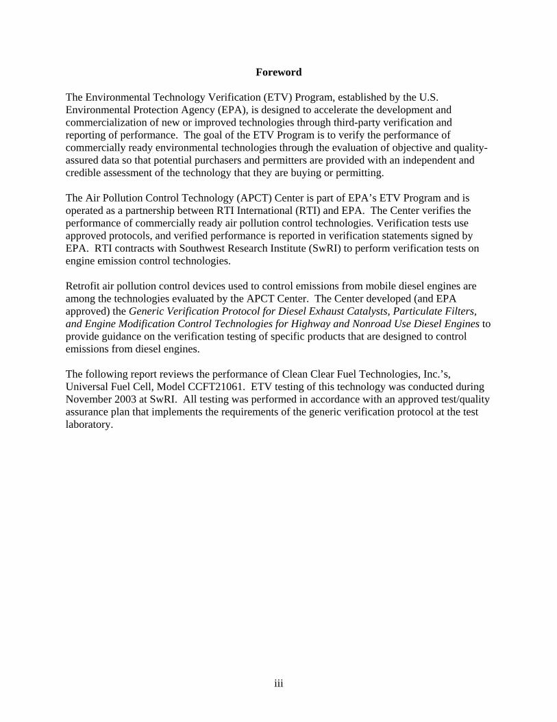
The Environmental Technology Verification (ETV) Program, established by the U.S. Environmental Protection Agency (EPA), is designed to accelerate the development and commercialization of new or improved technologies through third-party verification and reporting of performance. The goal of the ETV Program is to verify the performance of commercially ready environmental technologies through the evaluation of objective and quality-assured data so that potential purchasers and permitters are provided with an independent and credible assessment of the technology that they are buying or permitting.
The Air Pollution Control Technology (APCT) Center is part of EPA’s ETV Program and is operated as a partnership between RTI International (RTI) and EPA. The Center verifies the performance of commercially ready air pollution control technologies. Verification tests use approved protocols, and verified performance is reported in verification statements signed by EPA. RTI contracts with Southwest Research Institute (SwRI) to perform verification tests on engine emission control technologies.
Retrofit air pollution control devices used to control emissions from mobile diesel engines are among the technologies evaluated by the APCT Center. The Center developed (and EPA approved) the Generic Verification Protocol for Diesel Exhaust Catalysts, Particulate Filters, and Engine Modification Control Technologies for Highway and Nonroad Use Diesel Engines to provide guidance on the verification testing of specific products that are designed to control emissions from diesel engines.
The following report reviews the performance of Clean Clear Fuel Technologies, Inc.’s, Universal Fuel Cell, Model CCFT21061. ETV testing of this technology was conducted during November 2003 at SwRI. All testing was performed in accordance with an approved test/quality assurance plan that implements the requirements of the generic verification protocol at the test laboratory.
iii
Availability of Report
Copies of this verification report are available from:
• RTI International Engineering and Technology Unit P.O. Box 12194 Research Triangle Park, NC 27709-2194
• U.S. Environmental Protection Agency Air Pollution Prevention and Control Division (E343-02) 109 T. W. Alexander Drive Research Triangle Park, NC 27711
Web sites: http://www.epa.gov/etv/verifications/verification-index.html (electronic copy) http://www.epa.gov/ncepihom/
iv

Table of Contents
Notice ............................................................................................................................................. ii
Foreword ........................................................................................................................................ iii
Availability of Report .................................................................................................................... iv
List of Figures ................................................................................................................................ vi
List of Tables ................................................................................................................................. vi
Acronyms/Abbreviations .............................................................................................................. vii
Acknowledgments........................................................................................................................ viii
Section 1.0 Introduction..................................................................................................................1
Section 2.0 Description of Products................................................................................................2
Section 3.0 Test Documentation .....................................................................................................4
3.1 Engine Description.......................................................................................................4
3.2 Engine Fuel Description ..............................................................................................4
3.3 Summary of Emissions Measurement Procedures.......................................................5
3.4 Deviations from the Test/QA Plan...............................................................................6
3.5 Documented Test Conditions.......................................................................................7
Section 4.0 Summary and Discussion of Emission Results............................................................9
4.1 Emissions Test Data.....................................................................................................9
4.2 Quality Assurance......................................................................................................11
Section 5.0 References..................................................................................................................12
Appendix A Vendor Comments................................................................................................. A-1
v

List of Figures
Figure Page
1. Mounting location of aged Universal Fuel Cell, Model 21061, Serial Number 0642, in Test Cell 8............................................................................................................................3
2. Constant volume sampler setup for emissions measurement. .................................................6
List of Tables
Table Page
1. Engine Identification Information ...........................................................................................4
2. Selected Fuel Properties and Specifications ............................................................................5
3. Engine Performance Data ........................................................................................................7
4. Magnetic Flux Density Measurements ....................................................................................8
5. Brake Specific Fuel Consumption ...........................................................................................8
6. Emissions Test Data.................................................................................................................9
7. Composite Weighted Emissions Values (English units) ......................................................10
8. Composite Weighted Emissions Values (metric units) .........................................................10
9. Summary of Verification Test Emission Values....................................................................11
10. Summary of Verification Test Emission Reductions.............................................................11
vi

Acronyms/Abbreviations
ºF degrees Fahrenheit ºC degrees Celsius APCT Air Pollution Control Technology ASTM American Society for Testing and Materials bhp brake horsepower bhp-h brake horsepower hour BSFC brake specific fuel consumption CCFT Clean Clear Fuel Technologies, Inc. CFR Code of Federal Regulations CO carbon monoxide CO2 carbon dioxide DDC Detroit Diesel Corporation EPA U.S. Environmental Protection Agency ETV Environmental Technology Verification FTP Federal Test Procedure ft foot (feet) g gram(s) HC hydrocarbon(s) HD heavy duty Hg mercury kW kilowatt(s) kWh kilowatt hour(s) kPa kilopascal(s) lb pound(s) lbf/ft pound force foot (feet) LSD low-sulfur diesel mm millimeter(s) N newton(s) N•m newton-meter NOx nitrogen oxide(s) OTAQ Office of Transportation and Air Quality Pa pascal(s) PDP Positive Displacement Pump PM particulate matter ppm parts per million by volume QA quality assurance QC quality control rpm revolutions per minute RTI RTI International SwRI Southwest Research Institute
vii

Acknowledgments
The authors acknowledge the support of all those who helped plan and conduct the verification activities. In particular, we would like to thank Mike Kosusko, the U.S. Environmental Protection Agency’s (EPA’s) Project Manager, and Paul Groff, EPA’s Quality Assurance Manager, both of whom are with EPA’s National Risk Management Research Laboratory in Research Triangle Park, NC. We would also like to acknowledge the assistance and participation of Clean Clear Fuel Technologies personnel who supported the test effort.
For more information on the Clean Clear Fuel Technologies, Inc., Universal Fuel Cell, contact:
Mr. John Montgomery Clean Clear Fuel Technologies, Inc. 2999 E. Dublin Granville Rd., Suite 101 Columbus, OH 43231 Telephone: (614) 882-0019 Fax: (614) 882-0849 Email: [email protected] Web site: http://www.cleanclearfuel.com
For more information on verification testing of mobile sources air pollution control devices, contact
Ms. Jenni Elion RTI International P.O. Box 12194 Research Triangle Park, NC 27709-2194 Telephone: (919) 541-6253 Email: [email protected] Web site: http://etv.rti.org/apct/index.html
viii

Section 1.0 Introduction
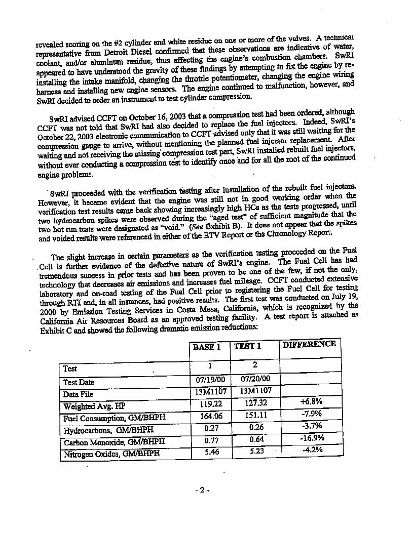
This report reviews the performance of the Clean Clear Fuel Technologies, Inc.’s (CCFT’s) Universal Fuel Cell, Model CCFT21061. Environmental Technology Verification (ETV) Program testing of this technology was conducted during a series of tests in November 2003 by Southwest Research Institute (SwRI) under contract with RTI International’s (RTI’s) Air Pollution Control Technology (APCT) Center. The objective of the APCT Center and the ETV Program is to verify, with high data quality, the performance of air pollution control technologies. Control of air emissions from diesel engines is within the scope of the APCT Center. An APCT Center program area was designed by RTI and a technical panel of experts to evaluate the performance of diesel exhaust catalysts, particulate filters, and engine modification control technologies for mobile diesel engines. Based on the activities of this technical panel, the Generic Verification Protocol for Diesel Exhaust Catalysts, Particulate Filters, and Engine Modification Control Technologies for Highway and Nonroad Use Diesel Engines1 was developed. The specific test/quality assurance (QA) plan addendum for the ETV test of the technology submitted by CCFT was developed and approved on August 27, 2003.2 The goal of the test was to measure the emissions control performance of the technology system and its emissions reduction relative to an uncontrolled engine.
A description of the Universal Fuel Cell is presented in Section 2. Section 3 documents the procedures and methods used for the verification test and the conditions under which the test was conducted. The results of the test are summarized and discussed in Section 4, and references are presented in Section 5.
This report contains only summary information and data as well as the verification statement. Vendor comments are included in Appendix A. Complete documentation of the test results is provided in a separate test report3 and audit of data quality (ADQ) report.4 These reports include the raw test data from product testing and supplemental testing, equipment calibration results, and QA and quality control (QC) activities and results. Complete documentation of QA/QC activities and results, raw test data, and equipment calibration results are retained in SwRI’s files for 7 years.
1
Section 2.0 Description of Products
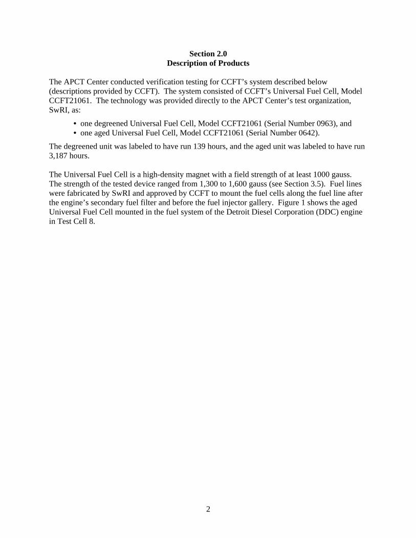
The APCT Center conducted verification testing for CCFT’s system described below (descriptions provided by CCFT). The system consisted of CCFT’s Universal Fuel Cell, Model CCFT21061. The technology was provided directly to the APCT Center’s test organization, SwRI, as:
• one degreened Universal Fuel Cell, Model CCFT21061 (Serial Number 0963), and • one aged Universal Fuel Cell, Model CCFT21061 (Serial Number 0642).
The degreened unit was labeled to have run 139 hours, and the aged unit was labeled to have run 3,187 hours.
The Universal Fuel Cell is a high-density magnet with a field strength of at least 1000 gauss. The strength of the tested device ranged from 1,300 to 1,600 gauss (see Section 3.5). Fuel lines were fabricated by SwRI and approved by CCFT to mount the fuel cells along the fuel line after the engine’s secondary fuel filter and before the fuel injector gallery. Figure 1 shows the aged Universal Fuel Cell mounted in the fuel system of the Detroit Diesel Corporation (DDC) engine in Test Cell 8.
2

Aged Universal Fuel Cell
Figure 1. Mounting location of aged Universal Fuel Cell, Model 21061, Serial Number 0642, in Test Cell 8.
3

Table 1. Engine Identification Information
Engine serial number 06R0422316
Date of manufacture April 1998 Make Detroit Diesel CorporationModel year 1998
Model Series 60Engine displacement and configuration 12.7-L, in-line 6-cylinder Service class On-highway, heavy-duty (HD) diesel engine EPA engine family identification WDDXH12.7EGD Rated power 298 kW (400 bhp) at 1,800 rpm Rated torque 2130 N•m (1550 lbf/ft) at 1,200 rpm Certified emission control system Electronic control Aspiration Turbocharged, air-to-air intercooledFuel system Direct injection, electronically controlled unit
injectors
Section 3.0 Test Documentation
The ETV testing took place at SwRI under contract to the APCT Center. Testing was performed in accordance with:
• Generic Verification Protocol for Diesel Exhaust Catalysts, Particulate Filters, and Engine Modification Control Technologies for Highway and Nonroad Use Diesel Engines;1
• Test/QA Plan for the Verification Testing of Diesel Exhaust Catalysts, Particulate Filters, and Engine Modification Control Technologies for Highway and Nonroad Use Diesel Engines;5 and
• Test-Specific Addendum to ETV Mobile Source Test/QA Plan for Clean Clear Fuel Technology Universal Fuel Cell;2 and
The generic verification protocol and the test/QA plan were available to the applicant prior to testing.
3.1 Engine Description
The ETV testing was performed using an inline, 6-cylinder, 12.7-liter, 1998 model year Detroit DDC, heavy-duty (HD), on-highway diesel engine. It was turbocharged and used a laboratory water-to-air heat exchanger for a charge air intercooler. The engine was owned by SwRI and has been used on various research programs. Table 1 provides the engine’s identification details.
3.2 Engine Fuel Description
The diesel fuel used during all test runs for this verification test was a conventional No. 2 low-sulfur diesel (LSD) fuel, with a sulfur level of 386 ppm. The LSD fuel meets EPA current diesel
4

fuel specifications given in 40 CFR 86.1313-98, Table N98-26. Selected fuel properties from suppliers’ analyses are summarized in Table 2.
Table 2. Selected Fuel Properties and Specifications
Item
Code of Federal Regulations (CFR) Specificationa Test Fuel
ASTM Type-2D Low-Sulfur Diesel
EM-4991-F
Cetane number D613 40–50 47.3
Cetane index D976 40–50 46.7
Distillation range: Initial boiling point, ºC (ºF) 10% Point, ºC (ºF) 50% Point, ºC (ºF) 90% Point, ºC (ºF) End point, ºC (ºF)
D86 D86 D86 D86 D86
171–204 (340–400) 204–238 (400–460) 243–282 (470–540) 293–332 (560–630) 321–366 (610–690)
177 (350) 207 (404) 258 (496) 302 (575) 328 (642)
Gravity (American Petroleum Institute)
D287 32–37 35.9
Specific gravity – 0.8453
Total sulfur, ppm D2622 (300–500)b 386
Hydrocarbon composition: Aromatics (minimum), % Paraffins, naphthenes, and olefins, %
D1319 D1319
27 c
30.6 69.4
Flash point (minimum), ºC (ºF) D93 54 (130) 67 (153)
Viscosity, centistokes @ 40 ºC D445 2.0–3.2 2.3
Note: ASTM = American Society for Testing and Materials. a Diesel fuel specification as in 40 CFR 86.1313-98(b)(2)6 for the year 1998 and beyond for heavy-duty diesel
engines. b 1998 sulfur range specification. c Remainder of the hydrocarbons.
3.3 Summary of Emissions Measurement Procedures
The ETV tests consisted of baseline uncontrolled tests and tests with the control system installed. The baseline engine and the installed Universal Fuel Cell were tested on conventional LSD fuel. The standard HD Transient Federal Test Procedure7 (FTP) for exhaust emissions testing was performed. The engine and control system were conditioned before the official tests with three hot-start transient cycles conducted in accordance with the test/QA plan.5 Individual exhaust gas and particulate matter (PM) samples were taken during the official tests for each cycle.
5

Emissions Test Procedures
Exhaust emissions were measured using HD Transient FTP7 and the experimental setup shown in Figure 2. Dilute exhaust emissions measured during tests over the transient FTP operating conditions included total hydrocarbons (HC), carbon monoxide (CO), carbon dioxide (CO2), nitrogen oxides (NOx), and exhaust PM. The CO and CO2 levels were determined using nondispersive infrared instruments. Total HC were measured using continuous sampling techniques employing a heated flame ionization detector. The NOx was measured continuously using a chemiluminescent analyzer.
Filter Pack
Engine
Gas Meter
Pump
Bag Sample
Gas Analyzer
Sample Line
Heated Line
90mm PM Filters
Sample Zone
Heat Exchanger
CO, CO2, HC, and NOx Background Bag Sample PM
Exhaust Pipe
CO, CO2 Sample Bag
NOx Analyzer
HC Analyzer Positive Displacement
Pump (PDP)
Dilution Air
10 Diameters Mixing Orifice
Figure 2. Constant volume sampler setup for emissions measurement.
The exhaust PM level for each test was determined using dilute sampling techniques that collected PM on a pair of 90-mm diameter Pallflex T60A20 filter media used in series. The particulate filter pair unit was weighed together both before and after each test to establish exhaust PM emissions for the test.
3.4 Deviations from the Test/QA Plan
The original test plan incorporated the use of a 1998 rebuilt Cummins ISM 370 ESP (Serial Number 34936044), HD diesel engine supplied by CCFT. Baseline emission tests with this engine resulted in a PM weighted composite average of 0.142 g/hph. This level exceeded the applicable certification standard (0.10 g/hph) by more than the allowable 10%. Upon further investigation, a water leak was found in the engine’s head and five pistons were noted to have the incorrect part number for the engine’s CPL.
6

After reviewing the situation, SwRI was instructed by CCFT to remove the Cummins engine and install a 1998 DDC Series 60 HD engine supplied by SwRI. During initial cold-start runs of the Series 60, cold-start HC levels were excessive. New rebuilt fuel injectors were installed, and baseline tests of the DDC engine showed that the engine did not exceed the applicable emission standards by more than 10%.
On November 21, 2003, a new battery charger was installed in Test Cell 8 to replace an older unit. Battery chargers are periodically replaced with new models to maintain equipment reliability. The charger maintains the charge on a 12-V battery, which powers the engine control module. The DDC Series 60 engine control module is very sensitive to low battery voltage. During hot-start tests 112103-H2 and 112103-H3, the DDC engine misfired, coinciding with HC concentration spikes that peaked out of the measurable range of 0–100 ppm. The HC spikes caused the tests to be voided as specified in the Code of Federal Regulations (CFR), Title 40, Part 86, Subpart N. Low battery voltage was determined to be the cause of the erratic engine behavior. The malfunctioning battery charger was replaced with a functional unit, a preparatory hot-start cycle was run, and two additional hot-start tests were conducted to complete the data set. No erratic behavior of the engine or HC concentration spikes were noted after the charger was replaced.
3.5 Documented Test Conditions
Engine Performance
Table 3 gives the observed engine performance while power validating the DDC engine for the baseline and the controlled configurations. The performance was similar for all configurations. Performance curves were generated by operating the engine at full load while increasing its speed by 8 rpm per second for both the baseline and controlled configurations.
Table 3. Engine Performance Data
Fuel Test Date Test Type Rated Powera
bhp (kW) Peak Torqueb
lbf/ft (N•m) LSD 11/18/2003 Baseline 422 (315) 1633 (2214) LSD 11/19/2003 Controlled 419 (312) 1630 (2210) LSD 11/20/2003 Controlled 420 (312) 1658 (2248)
Engine Exhaust Backpressure The engine backpressure was set to 2.4 in Hg (8.1 kPa) at rated speed and load in accordance with the engine manufacturer specifications.
Universal Fuel Cell Magnetic Flux Density An AlphaLab, Inc., DC Magnetometer, Serial Number 1187, was supplied by CCFT to measure the magnetic flux density of each fuel cell both before and after the cells were emission tested. Triplicate readings were recorded for each measurement and are given in Table 4.
7

Table 5. Brake Specific Fuel Consumption
Test Number Test Type Test Date BSFC,
lb/bhp-h BSFC,
kg/kWh
Weighted BSFC,
lb/bhp-h
Weighted BSFC,
kg/kWh
Engine Baseline
111903-C1 Cold-start 11/19/2003 0.424 0.257
111903-H1 Hot-start 11/19/2003 0.401 0.243 0.404 0.245
111903-H2 Hot-start 11/19/2003 0.404 0.244 0.407 0.246
111903-H3 Hot-start 11/19/2003 0.401 0.243 0.404 0.245
Engine with Degreened Fuel Cell
112003-C1 Cold-start 11/20/2003 0.42 0.254
112003-H1 Hot-start 11/20/2003 0.405 0.245 0.407 0.246
112003-H2 Hot-start 11/20/2003 0.404 0.244 0.406 0.246
112003-H3 Hot-start 11/20/2003 0.402 0.243 0.405 0.245
Engine with Aged Fuel Cell
112103-C1 Cold-start 11/21/2003 0.423 0.256
112103-H1 Hot-start 11/21/2003 0.406 0.246 0.408 0.247
112103-H4 Hot-start 11/21/2003 0.399 0.241 0.402 0.243
112103-H5 Hot-start 11/21/2003 0.399 0.241 0.402 0.243
Table 4. Magnetic Flux Density Measurements
Unit Test Stage Test Date Reading #1,
gauss Reading #2,
gauss Reading #3,
gauss Degreened Cell (SN 0963) Pre-test 11/19/2003 1500 1600 1600 Degreened Cell (SN 0963) Post-test 11/20/2003 1434 1585 1523 Aged Cell (SN 0642) Pre-test 11/20/2003 1420 1540 1370
Aged Cell (SN 0642) Post-test 11/26/2003 1413 1307 1495
Fuel Consumption Table 5 presents the brake specific fuel consumption (BSFC) for all baseline and control configurations.
Note: BSFC = brake specific fuel consumption.
8

1• ECOLD +
6 • (EHOT )m
(ECOMP)m = 17 7
6 •WCOLD + • (WHOT )m
7 7
Section 4.0 Summary and Discussion of Emission Results
4.1 Emissions Test Data
The baseline and controlled emissions data are summarized in Tables 6, 7, and 8. The emissions were measured at each test point for HC, CO, NOx, and PM. Table 6 also provides data on CO2 emissions and work. For each pollutant/hot-start test combination, the transient composite-weighted emissions per work (bhp-h) were then calculated following the fractional calculation for highway engines as follows:
(Eq. 1)
where ECOMP = composite emissions rate, g/bhp-h m = one, two, or three hot-start tests
ECOLD = cold-start mass emissions level, g EHOT = hot-start mass emissions level, g
WCOLD = cold-start brake horsepower hour, bhp-h WHOT = hot-start brake horsepower hour, bhp-h.
These composite-weighted emissions rates are shown in Tables 7 and 8 and were used to calculate the mean and standard deviations for the baseline and controlled emissions rates. These data were in turn used to calculate mean emissions reductions and 95% confidence limits. These calculations are based on the generic verification protocol1 and test/QA plan.5
Table 6. Emissions Test Data
Test Number
Test Type
Test Date
g Work, KWh
(bhp-h) Exhaust
PM NOX HC CO CO2
Engine Baseline 111903-C1 Cold-start 11/19/03 3.09 128 13.2 66.9 18.5 22.8 (30.5)
111903-H1 Hot-start 11/19/03 2.22 121 4.74 36.8 17.5 22.6 (30.3)
111903-H2 Hot-start 11/19/03 2.22 125 3.28 35.2 17.7 22.6 (30.3)
111903-H3 Hot-start 11/19/03 2.26 126 3.18 35.5 17.5 22.6 (30.3)
Engine Controlled with Degreened Fuel Cell
112003-C1 Cold-start 11/20/03 4.02 130 18.5 68.2 18.3 22.8 (30.5)
112003-H1 Hot-start 11/20/03 2.26 124 3.96 37.3 17.7 22.6 (30.3)
112003-H2 Hot-start 11/20/03 2.21 123 3.14 37.1 17.6 22.6 (30.3)
112003-H3 Hot-start 11/20/03 2.21 129 2.45 36.3 17.5 22.6 (30.3)
Engine Controlled with Aged Fuel Cell 112103-C1 Cold-start 11/21/03 4.91 128 23.1 70.5 18.4 22.7 (30.4)
112103-H1 Hot-start 11/21/03 2.47 124 4.44 40.4 17.7 22.6 (30.3)
112103-H4 Hot-start 11/21/03 2.31 123 3.94 37.4 17.4 22.7 (30.4)
112103-H5 Hot-start 11/21/03 2.37 124 5.22 38.6 17.5 22.7 (30.4)
9

Table 7. Composite Weighted Emissions Values (English units)
Test Number
Test Date
g/bhp-h
Exhaust PM NOX HC CO CO2
Engine Baseline 111903-H1 11/19/03 0.0772 4.00 0.196 1.35 581
111903-H2 11/19/03 0.0772 4.13 0.155 1.31 585
111903-H3 11/19/03 0.0784 4.17 0.152 1.32 581
Engine Controlled with Degreened Fuel Cell 112003-H1 11/20/03 0.0828 4.12 0.199 1.38 585
112003-H2 11/20/03 0.0814 4.09 0.176 1.37 584
112003-H3 11/20/03 0.0814 4.26 0.156 1.35 581
Engine Controlled with Aged Fuel Cell 112103-H1 11/21/03 0.0931 4.11 0.235 1.48 587
112103-H4 11/21/03 0.0883 4.09 0.220 1.39 579
112103-H5 11/21/03 0.0898 4.09 0.256 1.42 578
Note: PM = particulate matter; NOx = nitrogen oxide; HC = hydrocarbon(s); CO = carbon monoxide; CO2 = carbon dioxide.
Table 8. Composite Weighted Emissions Values (metric units)
Test Test g/kWh Number Date Exhaust PM NOX HC CO CO2
Engine Baseline 111903-H1 11/19/03 0.103 5.36 0.263 1.81 779
111903-H2 11/19/03 0.103 5.54 0.208 1.76 784
111903-H3 11/19/03 0.105 5.59 0.204 1.77 779
Engine Controlled with Degreened Fuel Cell 112003-H1 11/20/03 0.111 5.52 0.267 1.85 784
112003-H2 11/20/03 0.109 5.48 0.236 1.84 783
112003-H3 11/20/03 0.109 5.71 0.209 1.81 779
Engine Controlled with Aged Fuel Cell
112103-H1 11/21/03 0.125 5.51 0.315 1.98 787
112103-H4 11/21/03 0.118 5.48 0.295 1.86 776
112103-H5 11/21/03 0.120 5.48 0.343 1.90 775
Note: PM = particulate matter; NOx = nitrogen oxide; HC = hydrocarbon(s); CO = carbon monoxide; CO2 = carbon dioxide.
10
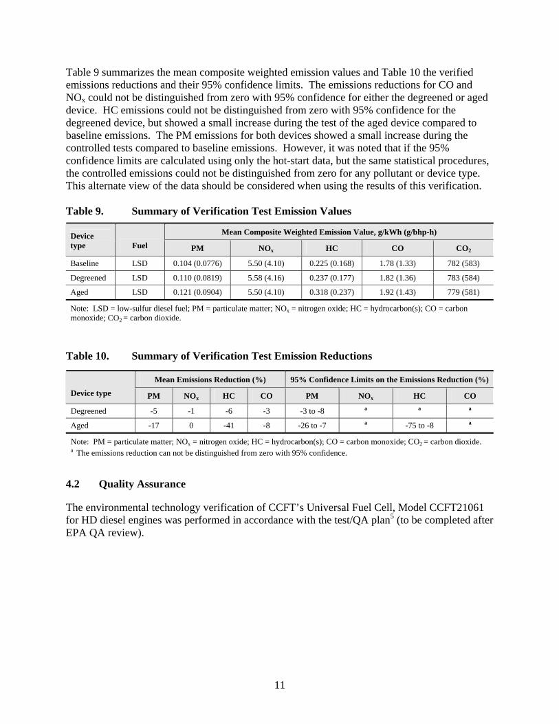
Table 9 summarizes the mean composite weighted emission values and Table 10 the verified emissions reductions and their 95% confidence limits. The emissions reductions for CO and NOx could not be distinguished from zero with 95% confidence for either the degreened or aged device. HC emissions could not be distinguished from zero with 95% confidence for the degreened device, but showed a small increase during the test of the aged device compared to baseline emissions. The PM emissions for both devices showed a small increase during the controlled tests compared to baseline emissions. However, it was noted that if the 95% confidence limits are calculated using only the hot-start data, but the same statistical procedures, the controlled emissions could not be distinguished from zero for any pollutant or device type. This alternate view of the data should be considered when using the results of this verification.
Table 9. Summary of Verification Test Emission Values
Device Mean Composite Weighted Emission Value, g/kWh (g/bhp-h) type Fuel PM NOx HC CO CO2
Baseline LSD 0.104 (0.0776) 5.50 (4.10) 0.225 (0.168) 1.78 (1.33) 782 (583)
Degreened LSD 0.110 (0.0819) 5.58 (4.16) 0.237 (0.177) 1.82 (1.36) 783 (584)
Aged LSD 0.121 (0.0904) 5.50 (4.10) 0.318 (0.237) 1.92 (1.43) 779 (581)
Note: LSD = low-sulfur diesel fuel; PM = particulate matter; NOx = nitrogen oxide; HC = hydrocarbon(s); CO = carbon monoxide; CO2 = carbon dioxide.
Table 10. Summary of Verification Test Emission Reductions
Device type
Mean Emissions Reduction (%) 95% Confidence Limits on the Emissions Reduction (%)
PM NOx HC CO PM NOx HC CO
Degreened -5 -1 -6 -3 -3 to -8 a a a
Aged -17 0 -41 -8 -26 to -7 a -75 to -8 a
Note: PM = particulate matter; NOx = nitrogen oxide; HC = hydrocarbon(s); CO = carbon monoxide; CO2 = carbon dioxide. a The emissions reduction can not be distinguished from zero with 95% confidence.
4.2 Quality Assurance
The environmental technology verification of CCFT’s Universal Fuel Cell, Model CCFT21061 for HD diesel engines was performed in accordance with the test/QA plan5 (to be completed after EPA QA review).
11

Section 5.0 References
1. RTI International (January 2002). Generic Verification Protocol for Diesel Exhaust Catalysts, Particulate Filters, and Engine Modification Control Technologies for Highway and Nonroad Use Diesel Engines. Research Triangle Park, NC: RTI International.
2. RTI International (August 2003). Test-Specific Addendum to ETV Mobile Source Test/QA Plan for Clean Clear Fuel Technology Universal Fuel Cell. Research Triangle Park, NC: RTI International.
3. Southwest Research Institute (December 2003). Environmental Technology Verification of a Clean Clear Fuel Technology, Inc. Universal Fuel Cell for Heavy-Duty Diesel Engines. San Antonio, TX: Southwest Research Institute.
4. Southwest Research Institute (December 2003). Audit of Data Quality for Environmental Technology Verification of a Clean Clear Fuel Technology, Inc. Universal Fuel Cell for Heavy-Duty Diesel Engines. San Antonio, TX: Southwest Research Institute.
5. RTI International (April 2002). Test/QA Plan for the Verification Testing of Diesel Exhaust Catalysts, Particulate Filters, and Engine Modification Control Technologies for Highway and Nonroad Use Diesel Engines. Research Triangle Park, NC: RTI International.
6. Fuel Specifications, 40 CFR 86.1313-98, Table N98-2 (updated July 2001).
7. 40 CFR 86, Subpart N, as of July 1, 1999, http://www.epa.gov/epahome/cfr40.htm.
12

Appendix A Vendor Comments
Clean Clear Fuel Technology, Inc. has been offered the opportunity to comment on the findings of this report. Their comments are presented in Appendix A of the report and reflect their opinions. The Air Pollution Control Technology Center and EPA do not necessarily agree or disagree with the vendor’s comments and opinions.
A-1