ep series heavy-duty, explosion proof connectors for ... · shell size 06 plug with ex d gland size...
TRANSCRIPT

EP SeriesHeavy-Duty, Explosion Proof
Connectors for Hazardous Environments
Cadillac EP Series
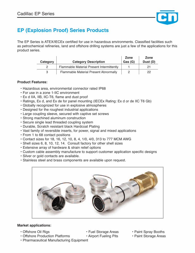
EP (Explosion Proof) Series Products
Product Features:• Hazardous area, environmental connector rated IP68• For use in a zone 1-IIC environment• Ex d IIA, IIB, IIC-T6, flame and dust proof• Ratings, Ex d, and Ex de for panel mounting (IECEx Rating: Ex d or de IIC T6 Gb)• Globally recognized for use in explosive atmospheres• Designed for the roughest industrial applications• Large coupling sleeve, secured with captive set screws• Strong machined aluminum construction• Secure single lead threaded coupling system• Durable, Scratch resistant black Hardcoat Plating• Vast family of reversible inserts, for power, signal and mixed applications• From 1 to 68 contact positions• Contact sizes for 18, 16, 12, 10, 8, 4, 1/0, 4/0, 313 to 777 MCM AWG• Shell sizes 6, 8, 10, 12, 14. Consult factory for other shell sizes• Extensive array of hardware & strain relief options• Custom cable assembly manufacture to support customer application specific designs• Silver or gold contacts are available.• Stainless steel and brass components are available upon request.
The EP Series is ATEX/IECEx certified for use in hazardous environments. Classified facilities suchas petrochemical refineries, land and offshore drilling systems are just a few of the applications for thisproduct series.
Zone ZoneCategory Category Description Gas (G) Dust (D)
2 Flammable Material Present Intermittently 1 213 Flammable Material Present Abnormally 2 22
Market applications:• Offshore Oil Rigs • Fuel Storage Areas • Paint Spray Booths• Offshore Production Platforms • Airport Fueling Pits • Paint Storage Areas• Pharmaceutical Manufacturing Equipment
1
Cadillac EP Series
Catalog Contents
EP Series Product Features Inside Cover
Plug & Receptacle Part Number Code Logic 2
Connector Component Overview 3
Connector Major Components 4
Straight Plug Assemblies 5
In-Line Receptacle Assemblies 6
Panel Mount Receptacle Assemblies 7
Fixed In-Line Receptacle Assemblies 8
Insert Configuration Introduction 9
Insert Configuration Listing 10
Insert Configuration Layouts 11-15
Cable Grip Components - Basket Weave Grips, Sealing Grommets & Washers 16
Ex d Gland Size and Cable Types 17
Contact Crimp Termination Tools 18
General Assembly Instructions and Precautions 19-24
Sales Offices & Representative Listing Back Cover
Clements National Company2150 Parkes Drive, Broadview, Illinois 60155 USAToll Free: 1-800-966-0016Direct/International: 708-594-5890 • Fax: 708-594-2481www.winchesterelectronics.com •www.clementsnational.com
Note: Printed catalogs may not have the latest updates.Please refer to our web site at: www.cadillacproducts.com for a pdf of the latest version of this catalog.

2
Cadillac EP Series
Part Number Examples
* - Consult factory for availability
EP15-4-1610-310PNShell size 10 In-line Receptacle with Basketweave Cable Grip, Cable O.D. 0.95",Insert #310 with Normal Key, Crimp Pin Contacts, 37 X 12 Awg
EP13-4-1610-310SNShell size 10 Plug with Basketweave Cable Grip, Cable O.D. 0.95",Insert #310 with Normal Key. Crimp Socket Contacts, 37 X 12 Awg
EP13-3-A06-327SNShell size 06 Plug with Ex d Gland Size A .3307"/8.4mm O.D. unarmored cable,Insert #327 with Normal Key. Crimp Socket Contacts 3 X 12 Awg
EP17-1-0006-327PNShell size 06 Panel Mount Receptacle for Potting,Insert #327 with Normal Key. Crimp Pin Contacts 3 X 12 Awg
Part Number Code Logic
EPS13-2-XXC06-310PKN1AExplosion Proof
Cable Types- Unarmored
A - Armored & SheathedB - Armored & Sheathed
with reduced bore
- Normal Key1, 2,...... 9 Alt. Key
- SolderN - Crimp
R - Pressure
P - PinS - Socket
Insert Configuration
13 - Plug15 - In-line Receptacle17 - Panel Mount Receptacle
Grommet Size for Shell Style 2 & 4 (see page 16)EEx d Gland Size required for Shell Style 3 (see page 17)
Style1 - Receptacle with Potting Adapter2 - Mechanical Clamp Nut3 - EEx d Gland4 - Basketweave Cable Grip
Material- Aluminum
S - Stainless SteelB - Brass
‘C’ Shell Shell Size
- Silver Plated ContactsK - Gold Plated Contacts
Potting material included for Styles 1, 2 & 4
Certification: Intertek IECEx ITS 10.0007X Ex d, EX de, IIC, T6, Gb, IP68

3
Cadillac EP Series
Connector Component Overview
Assembled Connector Part Number examples:
EnvironmentalPlug Cover
EnvironmentalReceptacle Cover
Receptacle ShellIn-line or Panelmount
Pin InsertSubassembly
Plug Shell &Coupling Nut
Socket InsertSubassembly
Cable Adapter Grommet Washer
Strain Relief Basket
Cable Adapter for EEx d Gland
Step Down Potting Adapterfor #6 Inline Receptacle
MechanicalClamp Nut
Gland Nut
EEx d Gland
Potting Adapter
EP15-2Black Hardcoated In-Line Receptacle withEnvironmental Cover & Mechanical Clamp
EP15-4Black Hardcoated In-Line Receptacle withEnvironmental Cover & Basket Weave Grip/Gland Nut
EP17-1Black Hardcoated Panel Mount Receptacle forpotting with Environmental Cover
EP13-3Black Hardcoated Plug with Environmental Coverand ATEX Gland Nut

4
The Cadillac EP Series is derived from the Clements CN Series, a UL and CSA certified ruggedized generalpurpose connector that has earned a reputation for performance and quality in the Industrial and Marine, Oil andGas Markets. As an outgrowth and variant of Mil-C-5015 threaded connectors the CN Series provides a flexibledesign for the toughest connector applications. In keeping with the same performance as the CN Series,Clements has introduced the EP Series, offering increased performance and explosion protection in hazardousenvironments. Clements has certified this connector series for use in a Zone 1, Gas IIC and Dust 21 environ-ments with IP68 environmental sealing characteristics and T6 temperature class.
The connector hardware is manufactured from a machined aluminum alloy with a durable hard anodized blackfinish. Alternate materials are available upon request by consulting the factory. The black hard anodized finishis scratch resistant and is available in the following shell styles; panel mount receptacle, fixed in-line receptacle,in-line receptacle and plug. The EP Series adds specially designed plug and receptacle shells with protectedcoupling nut and environmental dust covers for hazardous locations. The same rugged backshell hardware asoffered in the CN Series is available; basketweave, mechanical clamp, standard gland nut (potting required) andEx d approved cable glands. The EP Series backshell hardware offers extended length cable adapters toprovide cable protection and ease of assembly of multiple cable terminations. Offered with customizable rubbercable grommets and washers to fit various cable OD’s these components provide the added environmentalsealing and performance required in hazardous applications. The plug connector coupling is designed for quickmating and unmating with a robust self-cleaning threaded design. Locking is provided on the plug coupling nutwith two allen head set screws. The EP Series connector hardware is specially designed for optimum interfacelength and tolerances to ensure explosion protection as certified in hazardous environments.
Clements offers a versatile, reverse gender, field installable insert system. All inserts can be supplied withalternate polarization to prevent unwanted mateability. This feature is especially useful in applications utilizingmultiple connectors of the same configuration. As on our CN Series a comprehensive range of inserts isavailable to suit wire sizes #18 awg to 4/0 awg in single or multiple or mixed configurations. Clements EP Seriesinsert configurations are listed on pages 11 – 15. Three insert styles are offered; crimp, solder or pressuretermination. Contacts are manufactured using high performance copper alloy with standard silver plating andoptional gold plating available. Please refer to insert chart on page 10 to determine available insert style. Whileeach of these styles provide a slightly different insert design, all insert types provide water, vapor, moisture anddust resistance. All three styles offer a rugged rigid front dielectric for pin and socket configurations. No matterwhich EP Series insert you select, the three termination styles offer versatility and serviceability without sacrificingperformance.
Cadillac EP Series
Explosion Proof Connector Major Components
In-Line Receptacle Assembly Plug Assembly
Gland Nut
Basketweave Grommet
Cable Adapter
Receptacle ShellRubber
Seal
Potted
Coupling Nut Plug Shell
RubberSeal
RubberSeal
Cable Adapter
Potted
Socket BackcapPin Backcap Socket FrontInsulator
Pin FrontInsulator
Grommet Gland Nut
Basketweave
5
Cadillac EP Series
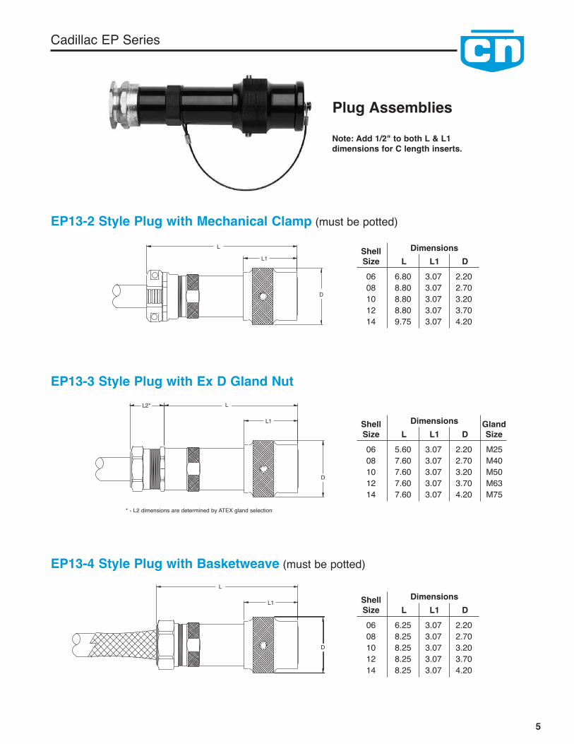
Plug Assemblies
EP13-2 Style Plug with Mechanical Clamp (must be potted)
ShellSize L L1 D
Dimensions
06 6.80 3.07 2.2008 8.80 3.07 2.7010 8.80 3.07 3.2012 8.80 3.07 3.7014 9.75 3.07 4.20
L
L1
D
EP13-3 Style Plug with Ex D Gland Nut
ShellSize
GlandSizeL L1 D
Dimensions
06 5.60 3.07 2.20 M2508 7.60 3.07 2.70 M4010 7.60 3.07 3.20 M5012 7.60 3.07 3.70 M6314 7.60 3.07 4.20 M75
LL2*
L1
D
EP13-4 Style Plug with Basketweave (must be potted)
ShellSize L L1 D
Dimensions
06 6.25 3.07 2.2008 8.25 3.07 2.7010 8.25 3.07 3.2012 8.25 3.07 3.7014 8.25 3.07 4.20
L
L1
D
* - L2 dimensions are determined by ATEX gland selection
Note: Add 1/2" to both L & L1dimensions for C length inserts.
6
Cadillac EP Series
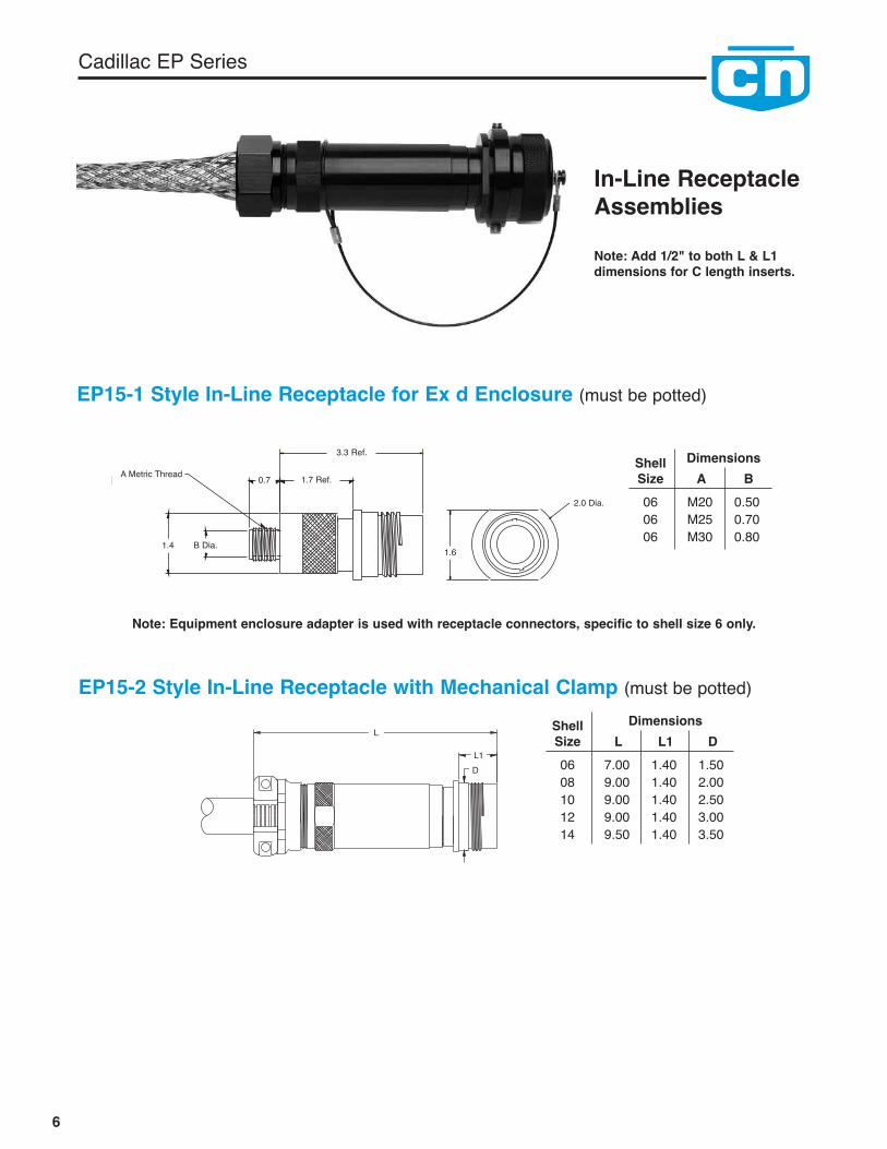
In-Line ReceptacleAssemblies
EP15-2 Style In-Line Receptacle with Mechanical Clamp (must be potted)
EP15-1 Style In-Line Receptacle for Ex d Enclosure (must be potted)
ShellSize L L1 D
Dimensions
06 7.00 1.40 1.5008 9.00 1.40 2.0010 9.00 1.40 2.5012 9.00 1.40 3.0014 9.50 1.40 3.50
ShellSize A B
Dimensions
06 M20 0.5006 M25 0.7006 M30 0.80
L
L1D
Note: Add 1/2" to both L & L1dimensions for C length inserts.
Note: Equipment enclosure adapter is used with receptacle connectors, specific to shell size 6 only.
3.3 Ref.
2.0 Dia.
0.7 1.7 Ref.
B Dia.1.4
A Metric Thread
1.6
7
Cadillac EP Series
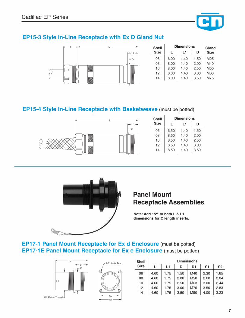
ShellSize L L1 D D1 S1 S2
Dimensions
06 4.60 1.75 1.50 M40 2.30 1.6508 4.60 1.75 2.00 M50 2.60 2.0410 4.60 1.75 2.50 M63 3.00 2.4412 4.60 1.75 3.00 M75 3.50 2.8314 4.60 1.75 3.50 M90 4.00 3.23
LL1D
7/32 Hole Dia.
D1 Metric Thread S2S1
EP15-3 Style In-Line Receptacle with Ex D Gland NutShellSize
GlandSizeL L1 D
Dimensions
06 6.00 1.40 1.50 M2508 8.00 1.40 2.00 M4010 8.00 1.40 2.50 M5012 8.00 1.40 3.00 M6314 8.00 1.40 3.50 M75
LL2
L1
D
EP15-4 Style In-Line Receptacle with Basketweave (must be potted)ShellSize L L1 D
Dimensions
06 6.50 1.40 1.5008 8.50 1.40 2.0010 8.50 1.40 2.5012 8.50 1.40 3.0014 8.50 1.40 3.50
LL1
D
EP17-1 Panel Mount Receptacle for Ex d Enclosure (must be potted)EP17-1E Panel Mount Receptacle for Ex e Enclosure (must be potted)
Panel MountReceptacle AssembliesNote: Add 1/2" to both L & L1dimensions for C length inserts.
Cadillac EP Series
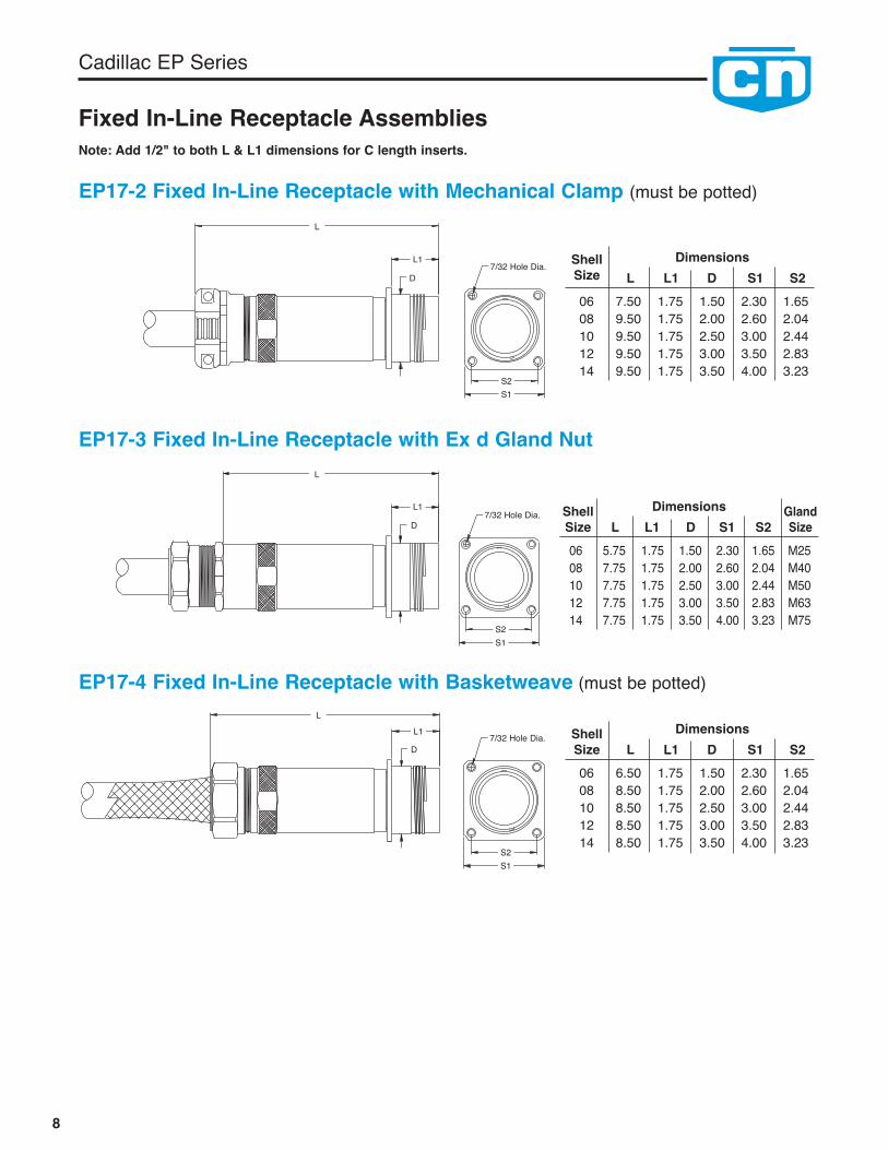
EP17-2 Fixed In-Line Receptacle with Mechanical Clamp (must be potted)L
L1
D
EP17-3 Fixed In-Line Receptacle with Ex d Gland NutL
L1
D
EP17-4 Fixed In-Line Receptacle with Basketweave (must be potted)
ShellSize L L1 D S1 S2
Dimensions
06 6.50 1.75 1.50 2.30 1.6508 8.50 1.75 2.00 2.60 2.0410 8.50 1.75 2.50 3.00 2.4412 8.50 1.75 3.00 3.50 2.8314 8.50 1.75 3.50 4.00 3.23
ShellSize
GlandSizeL L1 D S1 S2
Dimensions
06 5.75 1.75 1.50 2.30 1.65 M2508 7.75 1.75 2.00 2.60 2.04 M4010 7.75 1.75 2.50 3.00 2.44 M5012 7.75 1.75 3.00 3.50 2.83 M6314 7.75 1.75 3.50 4.00 3.23 M75
ShellSize L L1 D S1 S2
Dimensions
06 7.50 1.75 1.50 2.30 1.6508 9.50 1.75 2.00 2.60 2.0410 9.50 1.75 2.50 3.00 2.4412 9.50 1.75 3.00 3.50 2.8314 9.50 1.75 3.50 4.00 3.23
LL1
D
Fixed In-Line Receptacle Assemblies
7/32 Hole Dia.
S2S1
7/32 Hole Dia.
S2S1
7/32 Hole Dia.
S2S1
8
Note: Add 1/2" to both L & L1 dimensions for C length inserts.

Cadillac EP Series
Insert ConfigurationsIntroductionPlug and receptacle contact inserts are selected according to requirements for Service Voltage Rating,Number of Contacts, Wire Size and Ampere Rating. Pin or socket inserts are interchangeable in maleand female barrels. The EP Line Insert Configuration Listing is used to identify various contact insertarrangements. For the engineer, it provides visual selection of the insert configuration needed to satis-fy his requirements. For the end user, the list provides general information useful in the termination ofplugs and receptacles. To aid the reader, the insert configurations are presented in numerical order,based on the number of contacts in each.
The male insert illustration shown below (and those on the following pages) is shown as it appearswhen viewed from the front. Contacts are shown by both physical position within the configuration andby contact number. The contact number corresponds to the contact position shown on the rear face ofthe insert illustrated as well as to both the front and rear faces of the mating insert. The symbol usedto show contact location is indicative of contact size. For example, the contact symbol in this illustra-tion represents a #8 contact. An explanation of contact symbols is presented on each page of the list-ing. Each drawing also provides data on normal and alternate key positions. Drawings are reducedfrom actual size of the insert configuration.
Note: Alternate keying or insert polarization is intended to resist improper intermating of plugs andreceptacles of like shell sizes and like insert arrangements.
Alternate Key Positions
Contact Location Numbers
Contact Size Symbol
Service Voltage Rating: A = 240V, B,D & E = 600V
Service Voltage Ratings (for variousspecifications)
N.E.C. voltage rating is designated bya service voltage rating letter which islisted in this table and corresponds tothe insert configurations listings onpages 11-15. The voltage to whichcontact inserts are limited is afunction of the dielectric separationbetween adjacent contacts andbetween contacts and shell.
ServiceVoltage
InchesNominal
InchesNominal
DCVolts RMS
ACVolts RMS
DCVolts RMS
ACVolts RMS
OverSurfaceDistance
Thru-AirSpacing
Non-CircuitBreaking
Mil-C-5015 Rating N.E.C. Rating *Non-
CircuitBreaking
CircuitBreaking
Instrument 1⁄16 - 250 200 - -A 1⁄8 1⁄16 700 500 250 240D 3⁄16 1⁄8 1250 900 600 600E 1⁄4 3⁄16 1750 1250 600 600B 5⁄16 1⁄4 2450 1750 600 600C 1 5⁄16 4200 3000 600 600
EP Series Electrical Performance
9
CRIMP SOLDER PRESSURE
GROUND CONTACT TERMINATIONCONTACTSSYMBOLS
AWG 18 16 12 10 8 4 1/0 4/0 350 MCM 500 MCM

Cadillac EP Series
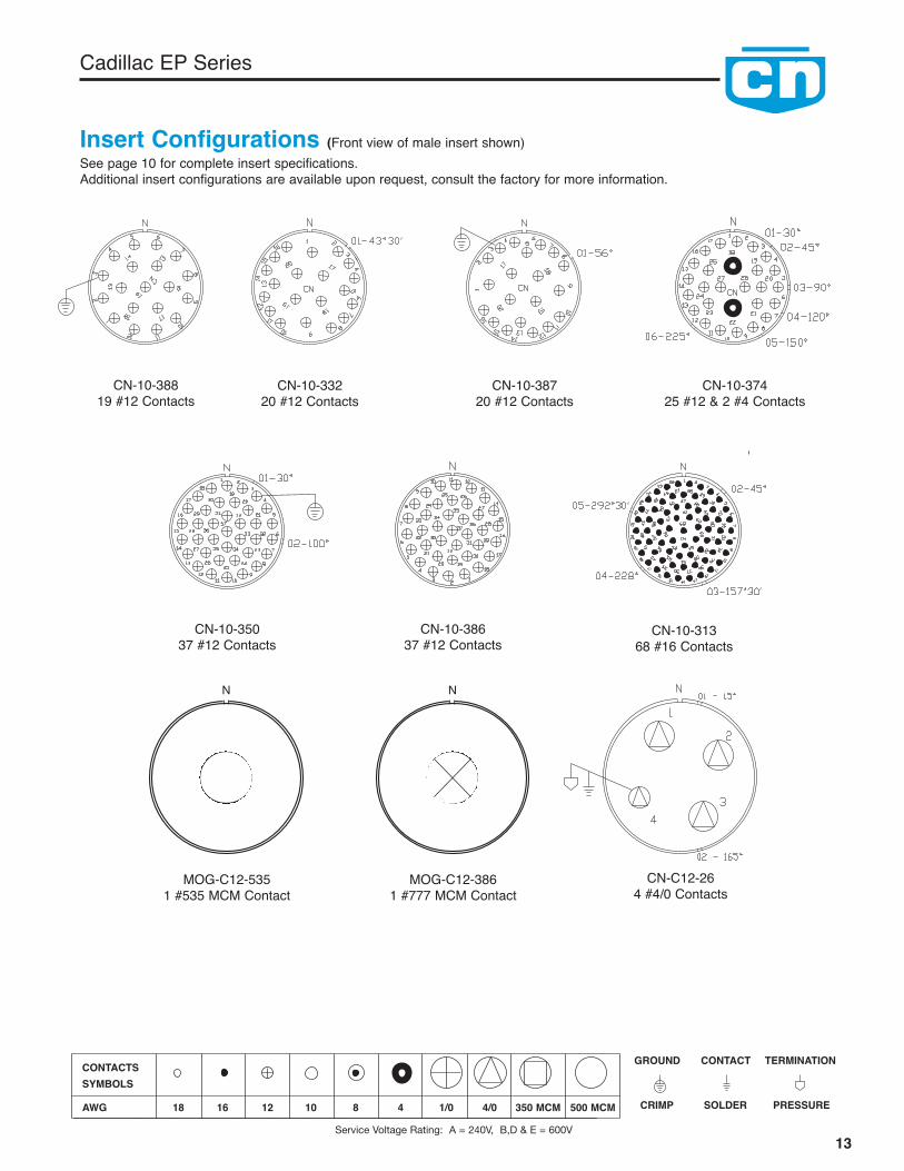
Insert Configurations
For the most current list of inserts please visit www.clementsnational.com10
Insert Total Service Contact Size PageArrangement Contacts Crimp Solder Pressure Rating 18 16 12 10 8 4 1/0 4/0 350 MCM No.CN-C10-379 1 X 1 kV Consult Factory for 313 to 777 MCM 12MOG-C12-535 1 X 1 kV Consult Factory for 313 to 777 MCM 13MOG-C12-777 1 X 1 kV Consult Factory for 313 to 777 MCM 13CN-06-327 3 X D 3 11CN-06-349 3 X D 3 11CN-06-314 4 X D 4 11CN-06-316 4 X D 4 11CN-06-322 4 X D 4 11CN-06-22 4 X D 4 11CN-06-333 4 X D 4 11CN-08-328 4 X D 4 11CN-08-22 4 X X D 4 11CN-08-38 4 X X D 4 11CN-C10-40 4 X X D 4 12CN-C10-42 4 X D 4 12CN-C12-26 4 X D 4 13CN-C12-38 4 X X D 4 14CN-06-324 5 X D 5 11CN-06-353 5 X D 5 11CN-08-316 5 X D 5 11CN-08-375 5 X D 5 11CN-10-38 5 X D 5 12CN-10-84 5 X D 5 12CN-C12-49 5 X E 5 14CN-C12-72 6 X D 3 3 14CN-06-310 7 X A 7 11CN-06-354 7 X A 7 11CN-06-348 7 X A 7 11CN-10-359 7 X D 7 12CN-C12-353 8 X A/B 4 4 14CN-C14-21 8 X D/E 4 4 15CN-C14-43 8 X D/E 4 4 15CN-06-355 10 X A 10 11CN-06-334 10 X A 10 11CN-08-376 10 X D 6 4 11CN-08-381 10 X D 6 4 12CN-10-380 10 X D 6 4 12CN-10-375 12 X D 12 12CN-08-325 16 X D 16 12CN-06-323 17 X A 17 Not ShownCN-08-312 19 X A 19 12CN-08-377 19 X A 19 12CN-08-355 19 X A 19 12CN-10-376 19 X D 19 12CN-10-388 19 X D 19 13CN-10-332 20 X A 20 13CN-10-387 20 X A 20 13CN-08-335 27 X A 24 3 12CN-10-374 27 X D/A 25 2 13CN-08-321 37 X A 37 12CN-10-350 37 X A 37 13CN-10-386 37 X A 37 13CN-12-371 37 X D 37 14CN-C14-12 39 X D 31 5 1 2 15CN-14-339 42 X D 42 15CN-C14-15 47 X D 43 3 1 15CN-12-352 58 X A 58 14CN-12-384 58 X A 58 14CN-08-333 61 X Inst. 61 Not ShownCN-10-313 68 X A 68 13
Cadillac EP Series
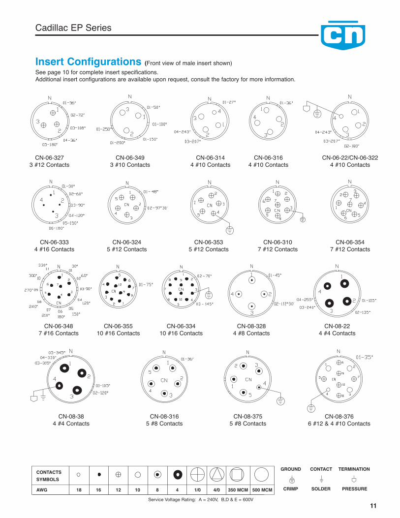
CN-06-3273 #12 Contacts
CN-06-3144 #10 Contacts
CN-06-3164 #10 Contacts
CN-06-3334 #16 Contacts
CN-06-3245 #12 Contacts
CN-06-3535 #12 Contacts
CN-06-3107 #12 Contacts
CN-06-3547 #12 Contacts
CN-06-3487 #16 Contacts
CN-06-35510 #16 Contacts
CN-06-33410 #16 Contacts
CN-06-22/CN-06-3224 #10 Contacts
CN-06-3493 #10 Contacts
CN-08-3284 #8 Contacts
CN-08-224 #4 Contacts
CN-08-384 #4 Contacts
CN-08-3165 #8 Contacts
CN-08-3755 #8 Contacts
CN-08-3766 #12 & 4 #10 Contacts
Insert Configurations (Front view of male insert shown)See page 10 for complete insert specifications.Additional insert configurations are available upon request, consult the factory for more information.
11Service Voltage Rating: A = 240V, B,D & E = 600V
CRIMP SOLDER PRESSURE
GROUND CONTACT TERMINATIONCONTACTSSYMBOLS
AWG 18 16 12 10 8 4 1/0 4/0 350 MCM 500 MCM
Cadillac EP Series
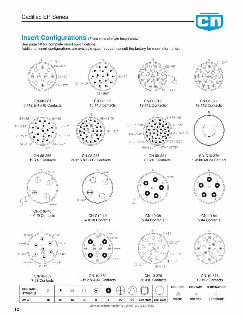
Insert Configurations (Front view of male insert shown)See page 10 for complete insert specifications.Additional insert configurations are available upon request, consult the factory for more information.
CN-08-3816 #12 & 4 #10 Contacts
CN-08-32516 #16 Contacts
CN-08-31219 #12 Contacts
CN-08-37719 #12 Contacts
CN-08-35519 #16 Contacts
CN-08-33524 #16 & 3 #12 Contacts
CN-C10-404 #1/0 Contacts CN-C10-42
4 #1/0 ContactsCN-10-38
5 #4 ContactsCN-10-84
5 #4 Contacts
CN-10-3597 #8 Contacts
CN-10-37512 #10 Contacts
CN-10-3806 #12 & 4 #4 Contacts
CN-10-37619 #12 Contacts
CN-08-32137 #16 Contacts
CN-C10-3791 #500 MCM Contact
N
12Service Voltage Rating: A = 240V, B,D & E = 600V
CRIMP SOLDER PRESSURE
GROUND CONTACT TERMINATIONCONTACTSSYMBOLS
AWG 18 16 12 10 8 4 1/0 4/0 350 MCM 500 MCM
Cadillac EP Series
CN-C12-264 #4/0 Contacts
MOG-C12-3861 #777 MCM Contact
CN-10-38720 #12 Contacts
CN-10-33220 #12 Contacts
CN-10-37425 #12 & 2 #4 Contacts
CN-10-35037 #12 Contacts
CN-10-38637 #12 Contacts
CN-10-31368 #16 Contacts
Insert Configurations (Front view of male insert shown)See page 10 for complete insert specifications.Additional insert configurations are available upon request, consult the factory for more information.
N
MOG-C12-5351 #535 MCM Contact
N
CN-10-38819 #12 Contacts
13Service Voltage Rating: A = 240V, B,D & E = 600V
CRIMP SOLDER PRESSURE
GROUND CONTACT TERMINATIONCONTACTSSYMBOLS
AWG 18 16 12 10 8 4 1/0 4/0 350 MCM 500 MCM
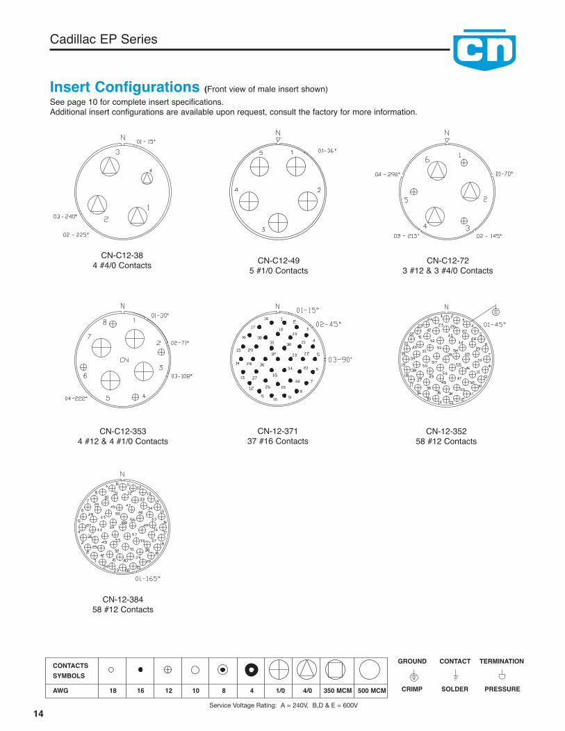
CN-C12-384 #4/0 Contacts CN-C12-49
5 #1/0 ContactsCN-C12-72
3 #12 & 3 #4/0 Contacts
CN-C12-3534 #12 & 4 #1/0 Contacts
Cadillac EP Series
CN-12-37137 #16 Contacts
CN-12-35258 #12 Contacts
CN-12-38458 #12 Contacts
Insert Configurations (Front view of male insert shown)See page 10 for complete insert specifications.Additional insert configurations are available upon request, consult the factory for more information.
14
CRIMP SOLDER PRESSURE
GROUND CONTACT TERMINATIONCONTACTSSYMBOLS
AWG 18 16 12 10 8 4 1/0 4/0 350 MCM 500 MCM
Service Voltage Rating: A = 240V, B,D & E = 600V
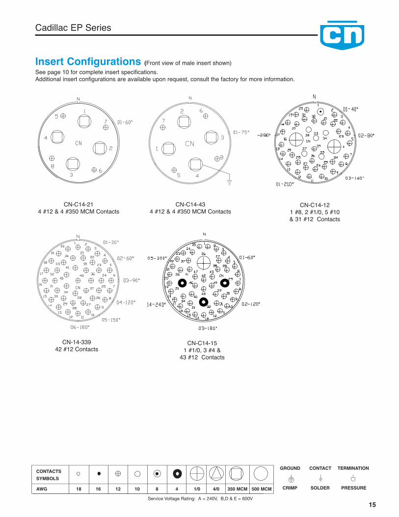
CN-C14-214 #12 & 4 #350 MCM Contacts
CN-C14-434 #12 & 4 #350 MCM Contacts
CN-C14-121 #8, 2 #1/0, 5 #10& 31 #12 Contacts
CN-C14-151 #1/0, 3 #4 &
43 #12 Contacts
CN-14-33942 #12 Contacts
15
Cadillac EP Series
Insert Configurations (Front view of male insert shown)See page 10 for complete insert specifications.Additional insert configurations are available upon request, consult the factory for more information.
Service Voltage Rating: A = 240V, B,D & E = 600V
CRIMP SOLDER PRESSURE
GROUND CONTACT TERMINATIONCONTACTSSYMBOLS
AWG 18 16 12 10 8 4 1/0 4/0 350 MCM 500 MCM

16
Cadillac EP Series
Cable Grip Components
CableDia.
CableDia.
NominalLength
Min.ShellSize
Cable Dia.Dimension
Max
CableDia.
CodeNo.*
Oil ResistantRubber
GrommetsPart No.
Steel GlandWashersPart No. Part No.
NominalLengthInches
Stainless SteelBasket Weave Grips
06 .062 .125 02 CN-6306-02C CN-8006-4E CN-5006-4E 3.125 .250 04 CN-6306-04C CN-8006-4E CN-5006-4E 3.250 .375 06 CN-6306-06C CN-8006-8E CN-5006-6E 4.375 .500 08 CN-6306-08C CN-8006-8E CN-5006-8E 5.500 .625 10 CN-6306-10C CN-8006-12E CN-5006-10E 6.625 .750 12 CN-6306-12C CN-8006-12E CN-5006-12E 7.750 .875 14 CN-6306-14C CN-8006-15E CN-5006-14E 7 1⁄2.875 .937 15 CN-6306-15C CN-8006-15E CN-5006-15E 8
08 .250 .375 06 CN-6308-06C CN-8008-8E CN-5008-6E 4.375 .500 08 CN-6308-08C CN-8008-8E CN-5008-8E 5.500 .625 10 CN-6308-10C CN-8008-12E CN-5008-10E 6.625 .750 12 CN-6308-12C CN-8008-12E CN-5008-12E 7.750 .875 14 CN-6308-14C CN-8008-16E CN-5008-14E 7 1⁄2.875 1.000 16 CN-6308-16C CN-8008-16E CN-5008-16E 8 1⁄21.000 1.125 18 CN-6308-18C CN-8008-20E CN-5008-18E 91.125 1.250 20 CN-6308-20C CN-8008-20E CN-5008-20E 101.250 1.375 22 CN-6308-22C CN-8008-23E CN-5008-22E 10 1⁄21.375 1.437 23 CN-6308-23C CN-8008-23E CN-5008-23E 10 1⁄2
10 & .500 .625 10 CN-6310-10C CN-8010-12E CN-5010-10E 6C10 .625 .750 12 CN-6310-12C CN-8010-12E CN-5010-14E 7 1⁄2
.750 .875 14 CN-6310-14C CN-8010-16E CN-5010-14E 7 1⁄2
.875 1.000 16 CN-6310-16C CN-8010-16E CN-5010-18E 91.000 1.125 18 CN-6310-18C CN-8010-20E CN-5010-18E 91.125 1.250 20 CN-6310-20C CN-8010-20E CN-5010-20E 101.250 1.375 22 CN-6310-22C CN-8010-24E CN-5010-24E 111.375 1.500 24 CN-6310-24C CN-8010-24E CN-5010-24E 111.500 1.625 26 CN-6310-26C CN-8010-28E CN-5010-28E 131.625 1.750 28 CN-6310-28C CN-8010-28E CN-5010-28E 131.750 1.875 30 CN-6310-30C CN-8010-31E CN-5010-31E 14 1⁄21.875 1.937 31 CN-6310-31C CN-8010-31E CN-5010-31E 14 1⁄2
12 & .875 1.000 16 CN-6312-16C CN-8012-16E CN-5012-16E 8 1⁄2C12 1.000 1.125 18 CN-6312-18C CN-8012-20E CN-5012-20E 10
1.125 1.250 20 CN-6312-20C CN-8012-20E CN-5012-20E 101.250 1.375 22 CN-6312-22C CN-8012-24E CN-5012-24E 111.375 1.500 24 CN-6312-24C CN-8012-24E CN-5012-24E 111.500 1.625 26 CN-6312-26C CN-8012-28E CN-5012-28E 131.625 1.750 28 CN-6312-28C CN-8012-28E CN-5012-28E 131.750 1.875 30 CN-6312-30C CN-8012-32E CN-5012-32E 151.875 2.000 32 CN-6312-32C CN-8012-32E CN-5012-32E 152.000 2.125 34 CN-6312-34C CN-8012-36E CN-5012-36E 162.125 2.250 36 CN-6312-36C CN-8012-36E CN-5012-36E 162.250 2.375 38 CN-6312-38C CN-8012-39E CN-5012-39E 17 1⁄22.375 2.437 39 CN-6312-39C CN-8012-39E CN-5012-39E 17 1⁄2
14 & 1.375 1.500 24 CN-6314-24C CN-8014-24E CN-5014-24E 13C14 1.500 1.625 26 CN-6314-26C CN-8014-28E CN-5014-28E 13
1.625 1.750 28 CN-6314-28C CN-8014-28E CN-5014-28E 131.750 1.875 30 CN-6314-30C CN-8014-32E CN-5014-32E 151.875 2.000 32 CN-6314-32C CN-8014-32E CN-5014-32E 152.000 2.125 34 CN-6314-34C CN-8014-36E CN-5014-36E 162.125 2.250 36 CN-6314-36C CN-8014-36E CN-5014-36E 162.250 2.375 38 CN-6314-38C CN-8014-40E CN-5014-40E 17 1⁄22.375 2.500 40 CN-6314-40C CN-8014-40E CN-5014-40E 17 1⁄22.500 2.625 42 CN-6314-42C CN-8014-44E CN-5014-44E 192.625 2.750 44 CN-6314-44C CN-8014-44E CN-5014-44E 192.750 2.875 46 CN-6314-46C CN-8014-46E CN-5014-46E 19
17
Cadillac EP Series
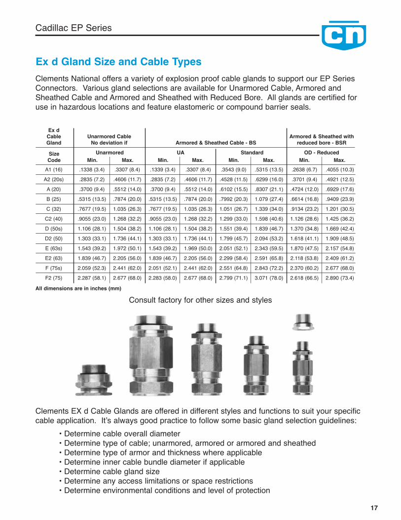
Ex d Gland Size and Cable Types
Min.SizeCode Max. Min. Max. Min. Max. Min. Max.A1 (16) .1338 (3.4) .3307 (8.4) .1339 (3.4) .3307 (8.4) .3543 (9.0) .5315 (13.5) .2638 (6.7) .4055 (10.3)A2 (20s) .2835 (7.2) .4606 (11.7) .2835 (7.2) .4606 (11.7) .4528 (11.5) .6299 (16.0) .3701 (9.4) .4921 (12.5)A (20) .3700 (9.4) .5512 (14.0) .3700 (9.4) .5512 (14.0) .6102 (15.5) .8307 (21.1) .4724 (12.0) .6929 (17.6)B (25) .5315 (13.5) .7874 (20.0) .5315 (13.5) .7874 (20.0) .7992 (20.3) 1.079 (27.4) .6614 (16.8) .9409 (23.9)C (32) .7677 (19.5) 1.035 (26.3) .7677 (19.5) 1.035 (26.3) 1.051 (26.7) 1.339 (34.0) .9134 (23.2) 1.201 (30.5)C2 (40) .9055 (23.0) 1.268 (32.2) .9055 (23.0) 1.268 (32.2) 1.299 (33.0) 1.598 (40.6) 1.126 (28.6) 1.425 (36.2)D (50s) 1.106 (28.1) 1.504 (38.2) 1.106 (28.1) 1.504 (38.2) 1.551 (39.4) 1.839 (46.7) 1.370 (34.8) 1.669 (42.4)D2 (50) 1.303 (33.1) 1.736 (44.1) 1.303 (33.1) 1.736 (44.1) 1.799 (45.7) 2.094 (53.2) 1.618 (41.1) 1.909 (48.5)E (63s) 1.543 (39.2) 1.972 (50.1) 1.543 (39.2) 1.969 (50.0) 2.051 (52.1) 2.343 (59.5) 1.870 (47.5) 2.157 (54.8)E2 (63) 1.839 (46.7) 2.205 (56.0) 1.839 (46.7) 2.205 (56.0) 2.299 (58.4) 2.591 (65.8) 2.118 (53.8) 2.409 (61.2)F (75s) 2.059 (52.3) 2.441 (62.0) 2.051 (52.1) 2.441 (62.0) 2.551 (64.8) 2.843 (72.2) 2.370 (60.2) 2.677 (68.0)F2 (75) 2.287 (58.1) 2.677 (68.0) 2.283 (58.0) 2.677 (68.0) 2.799 (71.1) 3.071 (78.0) 2.618 (66.5) 2.890 (73.4)
Unarmored CableNo deviation if
Ex dCableGland Armored & Sheathed Cable - BS
Unarmored UA Standard OD - Reduced
Armored & Sheathed withreduced bore - BSR
Clements National offers a variety of explosion proof cable glands to support our EP SeriesConnectors. Various gland selections are available for Unarmored Cable, Armored andSheathed Cable and Armored and Sheathed with Reduced Bore. All glands are certified foruse in hazardous locations and feature elastomeric or compound barrier seals.
Clements EX d Cable Glands are offered in different styles and functions to suit your specificcable application. It’s always good practice to follow some basic gland selection guidelines:
• Determine cable overall diameter• Determine type of cable; unarmored, armored or armored and sheathed• Determine type of armor and thickness where applicable• Determine inner cable bundle diameter if applicable• Determine cable gland size• Determine any access limitations or space restrictions• Determine environmental conditions and level of protection
Consult factory for other sizes and stylesAll dimensions are in inches (mm)

18
Cadillac EP Series
Contact Crimping and Insertion/Removal ToolsFull Cycle Crimp ToolTC-CN-M309This tool is a full cycle crimp tool for crimping Clementscrimp contact sizes #10 AWG through #16 AWG.(to be used with following locator dies TC-CN-XX-20L)
Locator Dies for TC-CN-M309 Crimp ToolTC-CN-10-20LLocator die for #10 AWG pin/socket crimp contactsTC-CN-12-20LLocator die for #12 AWG pin/socket crimp contactsTC-CN-16-20LLocator die for #16 AWG pin/socket crimp contacts
Insertion Tool for Pin/Socket Crimp ContactsTI-10HInsertion tool for #10 AWG pin/socket crimp contact.TI-12HInsertion tool for #12 AWG pin/socket crimp contact.TI-16HInsertion tool for #16 AWG pin/socket crimp contact.
Removal Tool for Pin Crimp ContactsTEP-LGRemoval tool for #8, #10 and #12 AWG pin crimp contact.TEP-SMRemoval tool for #16 AWG pin crimp contact.
Removal Tool for Crimp Socket ContactsTES-10HRemoval tool for #10 socket crimp contact.TES-12HRemoval tool for #12 socket crimp contact.TES-16HRemoval tool for #16 socket crimp contact.
Note: To order complete insertion/removal tool kits per contact size use the following part numbers:TCN-10 (#10 AWG), TCN-12 (#12 AWG), TCN-16 (#16 AWG).
Consult the factory for availability of crimping tools for other wire size contacts.

19
Cadillac EP Series
General Assembly Instructions and Precautions
1. Read assembly instructions before actually starting toassemble connectors to identify the various componentparts, and to check for any missing parts.
2. Cut cable jacket and sheathing squarely and to correctlength, using wire strippers that have been approved for theoperation. In preparing the individual wires in cables andharnesses for assembly, make allowances in length forreaching the outer most circle of contact cavities in the con-ductors. The insulation should be cut progressively longeras they extend out from the center of the cable or harness toassure sufficient length.
3. Follow the Contact Rating/Dimensions Table coveringmaximum cable stripping lengths for effective cable glandsealing. All conductors should be fit into contact wire wellscorrectly. A practice layout should be done so that anassembler can oversee what the finished termination willlook like.
a. Crimping and terminating of conductors to contactsmust be done carefully. Make certain that all wire strandsare fully bottomed in contact wells by checking throughinspection hole provided.
b. When contacts are to be soldered, avoid directcontact of soldering tools to inserts. An open flame or hotsoldering tip can carbonize insulating materials and makethem useless.
c. Soldering conductors to contacts must be donecarefully and a non-conductive flux should be used to avoidcorrosion or hygroscopic action. Do not use solder salts oracids, because they may affect the dielectric properties ofinsulation materials.
4. Before starting actual termination of wires, it is essentialthat cables and harnesses be laid out in a specific order inaccordance with the wiring diagram. Proper layout willeliminate the need for twisting and crossover of conductors.If the wiring layout is not correct, the termination operationwill be difficult or even impossible and the chances for mak-ing errors will be increased. Cable and harness assemblieshaving a spiral layout must also be matched carefully to thecorrect contacts in both the male and female inserts.
5. Some cables that will be used will have a “basket weave”type of armor under the outer jacket (sheath) and over theinner jacket. Since many regulatory entities require that thearmor be grounded at least at the source end, it is beneficialto ground the armor via a spare contact within the connector.Follow the removal of sufficient amount of armor can beclipped away, but not all. An adequate amount shouldremain in order that a small cross-section conductor, short inlength, be woven into the remaining armor weave and eithersoldered or covered with mastic impregnated heat shrink,creating an intimate bond to the armor. At the opposite endof the short piece of wire a contact should be crimped andinserted into the insert.
6. Use only correctly sized and provided Exd glands toassure resistance to moisture and other contaminates. Useonly correct size sealing grommets to assure resistance tomoisture and other contaminants. Make certain that thecable jacket is smooth where a grommet is to seal. Removeany grooves or ridges if present by sanding or scarfing.
7. Use only the proper crimping tools that have been set orcalibrated with precision gages. See Crimping andInsertion/Removal Tools page.
8. Make certain that all contacts are the correct size beforeattempting to assemble in insert cavities. This point is partic-ularly important when both power and control types of con-tacts are used in the same connector.
9. Be sure that ground contacts are correctly located.
10. Seat all contacts properly so that they will not bedamaged or become disengaged during connector matingoperation.
11. Use only the proper insertion tools and be sure thatthey are aligned axially when pushing contact into their fullyseated position. See Crimping and Insertion/Removal Toolspage.
12. When inserts have more cavities then the conductors,plug unused cavities with furnished contacts.
13. After all terminated contacts are inserted in theirrespective cavities and inspected, the cable adapter or insertclamp nut should be tightened with a wrench. This assemblyoperation should be done by placing the components in avise with smooth-faced jaws and using a strap wrench.
14. When handling cables, use adequate support to preventdamage to the internal wires. Exd glands are intended forsealing purposes and should not be used as a cable grip.
15. If for any reason terminated conductors have to beremoved from an insert because of any assembly error orchange in circuitry, be sure to remove the cable clamp orinsert clamp nut first before extracting the contact andreinserting it. This step is important because any attempt toremove the contacts when the resilient insulator componentsare compressed will result in damage.
16. If one of the connector poles is a ground wire, makesure that it is grounded properly before the connectoractually is engaged.
17. When connectors using the same configurationare mounted close together, different or alternate keyarrangements should be used to prevent mismatching andpossible damage to the electrical system.
20
Cadillac EP Series
18. Always inspect all aspects of a connector before actualoperation. It is recommended that normal DWV and IR testsbe performed on assemblies before using.
19. Never try to straighten bent contacts. Straighteningcannot be done properly and the plating on contacts verylikely will be marred. This will result in a high resistanceconnection and will expose the base material to possiblecorrosion.
20. A careful review should be made of the mixinginstructions that follow. Potting of the connector whererequired should be the very last step the assembler doesprior to fastening down the grommet and nut on the cableadapter. ‘Ringing’ out of the contacts with their mate shouldbe done prior to potting. Review the mixing instructions forpotting compound carefully. Refer to proper compound forshell size.
21. When potting connectors, be sure to apply potting onlyin mated condition to assure that contacts will align properly.
22. Each assembly operator should be his own inspector.Worn, damaged, or defective tools should be reportedimmediately to foreman and supervisors. Assembly operatorsshould be indoctrinated with this attitude and made tounderstand the importance of always guarding quality.Assembly workmanship is a significant factor in assuring thequality of multiple contact connectors. Quality cannot be“inspected” into connectors; it must be “built-in” during eachand every assembly operation
23. Do not attempt to remove inserts that are bonded orlocked in place in their shells.
24. Be certain that all components or connectors areassembled. Each part performs a vital function and it wouldnot be included if it wasn’t useful.
25. The equipment may be used with flammable gases andvapors with apparatus group(s) IIA, IIB, & IIC and withtemperature classes T6.
26. The equipment is only certified for use in ambienttemperatures in the range -20°C to +40°C and should not beused outside this range.
INSTALLATION, INSPECTION, MAINTENANCE and REPAIR
Installation shall be carried out by suitably-trained per-sonnel in accordance with the European standards andlocal code of practice.
It is the end user’s responsibility to ensure that the prod-uct, as specified and confirmed by the product label, issuitable for its intended application.
Inspection and maintenance of this equipment shall becarried out by suitably trained personnel in accordancewith the European standards and local code of practice.
Repair of this equipment shall be carried out by suitablytrained personnel in accordance with the Europeanstandards and local code of practice.
The certification of this equipment relies upon thefollowing materials used in its construction:
Connector Material: ASTM B211 or B221 6061-T6 AluminumO-ring Seal Material: Buna Rubber and Neoprene withDurometer of 60 SHORE APotting Compound: 3M Scotchcast Resin4 or TS-22.
If the equipment is likely to come into contact withaggressive substances, then it is the responsibility of theuser to take suitable precautions that prevent it from beingadversely affected, thus ensuring that the type of protectionprovided by the equipment is not compromised.
Aggressive substances: e.g. acidic liquids or gases that mayattack metals, or solvents that may affect polymeric materials.
Suitable precautions: e.g. regular checks as part of routineinspections should be established looking for corrosion andexposure to aggressive substances.
SPECIAL CONDITIONS FOR SAFE USE:
The “X” suffix to the certificate number relates to the following special conditions(s) for safe use:1. When installed there shall be adequate protection fromoverloading.
2. The connectors fully tightened in accordance with manufacturer’s specifications.
3. Plug/Receptacle covers are to be fitted when the connectors are not mated.
4. Plugs are not permitted to remain energized when notengaged to the receptacles as per EN 60079-0; clause 20.2
5. No modifications allowed on the flamepath of the connectors.
6. For plugs and receptacles that use certified cable glands,the gland must have a temperature range at their point ofmounting between -20°C to 85°C.
7. The connectors have no external earth/ground, an internalpin is made available for earthing/grounding. Local installationrequirements shall be applied. Power through the connectorshall not exceed the values specified in the instruction manual.
8. When panel mount variant must be installed in a suitablycertified Ex e enclosure, when the enclosure allows for suchinstallation. When used in a dust environment the enclosuremust also carry suitable Ex tD certification. After installationto “e” enclosures a dielectric strength test must be made perEN 60079-7 Clause 6.1 and must not be subjected to a service temperature greater than 70°C
Important Note: Always refer to Certificate No:ITS08ATEX15968X special conditions for safe use.(IECEx ITS 10.0007X)

21
Cadillac EP Series
Contact Preparation Instructions
Crimp Tools: See Tool Page for choice of turret head and selection settingaccording to contact size, part number and wire gage size.
Setting Up and Operation: Consult Tool Manufacturer
Wire Preparation and Crimping:Strip wire to required length. See Contact rating anddimensions table below . When using hot wire stripping donot wipe melted insulation material on wire strands; withmechanical strippers do not cut or nick strands.
Connector Assembly Instructions
Assembling In-Line Plug and In-Line Receptacle Connectors
1. Slide the specified components onto the cable about 12”,threaded end last.
a. When specified, slide the cable mechanical strainrelief nut, grommet washer and grommet onto the cable.
b. When specified, slide the required Atex gland (thread-ed end last) onto the cable.
2. Slide the Cable Adapter onto the cable, up to the EXGland, large diameter first.
3. Slide the Coupling nut onto the cable, up to the CableAdapter, Grub Screw end first when required.
4. Group all conductors according to size to facilitate orderlytermination.
5. Working on one conductor at a time, strip the insulationoff per the wire stripping length given in Figure 1 andterminate a contact to it, using a properly adjusted crimp tool,following crimp instruction found in Contact PreparationInstructions. Repeat the process for each conductor.Populate the insert with contacts by poking each of the wiredcontacts into its respective insert cavity following an electricalschematic or the system you are wiring.
6. For Plug Assemblies, make sure the Grub Screws arefully retracted then slide the Coupling Nut up onto the plugshell until seated against it’s mating shoulder.
7. Thread the Cable Adapter onto the plug shell, and handtighten.
8. Thread the EX Gland onto the Cable adapter, and handtighten.
9. Using a strap wrench, fully tighten the cable adapter ontothe plug shell.
10a. For Ex Gland Assemblies:Position the cable correctly. Using a hex wrench, tighten theEx Gland. The seal must grip the outer jacket of the cablewhen the cable gland is tightened. Tighten Back Nut (orConduit Receptor) to Entry Body. Ensure seal makes fullcontact with cable sheath. Tighten an extra 1-1/2 turns (upto 2-1/2 turns for minimum cable).
10b. For mechanical and Basket Weave Assemblies:Follow potting instructions prior to installation of grommetand mechanical clamp or basket weave hardware.
Contact Ratings/Dimensions Wire Well Dimensions - All Min. in inches (mm)
Dia.
ContactSize
AWG/MM
N.E.C.AmpereRating**
SolderDepth Dia.
Crimp*Depth
#18 (0.75) 9 .060 (1.52) .203 (5.15) .059 (1.49) .375 (9.52) 38 (169.0) –#16 (1.5) 16 .078 (2.00) .203 (5.15) .078 (2.00) .500 (12.70) 50 (222.4) –#12 (4.0) 30 .110 (2.80) .250 (6.45) .110 (2.80) .500 (12.70) 110 (489.3) –#10 (6.0) 40 .142 (3.60) .394 (10.00) .142 (3.60) .591 (15.00) 180 (800.7) 15 (1.7)#8 (10.0) 50 .209 (5.30) .516 (9.12) .189 (4.80) .748 (19.00) 225 (1000) 25 (2.8)#4 (25.0) 90 .329 (8.35) .580 (14.70) .285 (7.24) .875 (22.20) 400 (1779) 20 (2.3)#1/0 (50.0) 155 .470 (11.50) .641 (16.30) .450 (11.40) .775 (19.70) 550 (2447) 50 (5.7)#4/0 (120.0) 225 .650 (16.50) .885 (22.50) .620 (15.70) 1.00 (25.40) 875 (3892) 100 (11.3)350 MCM 325 – – – – – –500 MCM 750 – – – – – –535 MCM 839 – – – – – –646 MCM 937 – – – – – –777 MCM 1048 – – – – – –
lbs. (N)
CrimpPullout
Pressure ContactTorque
in./lbs. (N.M)
* - Includes wire inspection holes.** - Maximum conductor ampacities must be calculated according to the specific insert selected and NEC Paragraph 310.15 and Table 310.16 so not toexceed the T6, 85°C connector shell rating.
22
Cadillac EP Series
Connector Mating Instructions:
CAUTION: Make sure power has been turned off from theconnectors before mating and un-mating.
Mating:1. Turn power off, then remove environmental covers fromtheir respective connectors, make sure to retract the lockinggrub screws to prevent thread damage.
2. Mating, insert the plug into the receptacle by hand, thendraw up the coupling nut by hand, using strap wrench fullytighten coupling nut to affect environmental seals. Tightenlocking grub screws. Inspect work. Turn power on.
Unmating:1. Turn power off, loosen locking grub screws, using strapwrench, loosen coupling nut fully. Remove plug from recepta-cle by hand.
2. Install respective environmental covers tighten with strapwrench and lock in place by using grub screws. Inspect workbefore turning power on.
Preparing a Bulkhead Receptacle Connector forEnclosure Mounting.
1. Slide the Bulkhead Adapter onto the cable, or conductorgroup; knurled end first.
2. Terminate each conductor with it’s proper contact.
3. Populate the insert with contacts by poking each of thewired contacts into it’s respective insert cavity, following anelectrical schematic for the system you are wiring.
4. Slide the bulkhead adapter back down the conductors,and screw it onto the panel mount receptacle.
5. Use a strap wrench to tighten the bulkhead adapter untilfully tightened to shoulder.
6. Referring to potting instructions, stand the assemblyvertical, conductors pointing up, and fill the adapter withcement to a level 1/16” below the top of the adapter. Aftercuring, this assembly is now permanently cemented, non-separable and non-repairable, and can be mounted to thebulkhead.
7. It is best to fit the connector to the bulkhead at a timewhen the free end of the cable is not terminated to the elec-trical system. If this is not possible, then it is necessary torotate the connector assembly counter-clockwise to wind thecable/conductors so that when the assembly is threaded intoa bulkhead in the subsequent instruction, the cable/conduc-tors regain their most natural position, once the connectoris mounted to the bulkhead. (Rotations required to bedetermined by end-user).
8. Thread the receptacle assembly into the bulkhead untilthe seal touches down, then tighten it by the smallest fractionof a revolution to the first instance that the mounting holesline up with the threaded enclosure holes.
9. Position the protective covers’ lanyard tab over one of themounting holes and screw a fastener through it. Apply theremaining fasteners to the other three holes with torquesuit¬able for screw size used.
10. Install the protective cover and tighten fully.
11. Secure both grub screws to prevent unauthorizedremoval.
Potting Instructions for sizes #6 to #10
All cable adapters, other than ones suited for mating with anEX-certified gland, must be filled with encapsulate (potted).The material certified for use in filling this connector line is3M Scotchcast Resin 4.
The user or installer shall consider the performance of thesematerials with regard to attack by aggressive substances thatmay be present in the hazardous area.
This material is a two-component casting system with a 1:1volumetric mix ratio. Typical cure times at 70°F (21ºC) are1-2 hours and at 50ºF (10ºC) 4-8 hrs.
The product is available in pre-measured “mix & dispense”packaging. Potting material should be warmed to at least60°F (16ºC). Follow the instructions on the package formixing and pouring.
Note: Refer to page 24 for potting material andinstructions for sizes larger than #10
More information is available by contacting the followingauthorized suppliers:
Clements National Company2150 Parkes DriveBroadview, IL 60155Toll Free: 1-800-966-0016Direct: 1-708-594-5890Fax: 1-708-594-2481E-mail: sales@clementsnational.comwww.clementsnational.comwww.winchesterelectronics.com

23
Cadillac EP Series
Bulkhead Adapter
Bulkhead adapters should be filled to a maximum of 1/16”below the top of the adapter. Care must be exercised sothat the potting compound does not contaminate the bulk-head threads, or spill onto the outer surfaces of thereceptacle flange.
In preparation for potting, the receptacle is to be mated toit’s corresponding plug, so that all contacts are mated and intheir optimal post-potted position. When potting, thereceptacle flange should be rigidly fixtured in a horizontalposition. This fixture must be capable of holding the matedconnector pair in that position for a minimum of 2 hours atroom temperature. The exiting conductor/cable should befixtured inline above the connector pair, during the entirecuring process.
Mixing/Potting Instructions for 3M Scotchcast Resin4material for sizes #6 to #10
1. CAUTION: Wear goggles or other eye protectionduring all operations. Do not use potting material thatis 2 years beyond the manufacturing date marked onthe package.
2. The potting compound is premeasured in “burst bag”packaging. This packaging consists of a single plasticbag that is compartmentalized into two chambers, eachcontaining one part of the two part compound. Thesegregating feature is called a burst seal.3. Lay the bag on a flat surface. Choosing either end of thebag that is parallel to the burst seal, start coiling/rolling thebag so that the compound in that half of the bag is pushedup against the burst seal.
4. Squeeze and apply pressure to the rolled side of the bagso that the compound bursts through the burst seal and joinsthe compound on the other side of the bag. Unroll the bag.
5. Mix the entire contents of the bag, by alternately squeez-ing the bag, and working the bag across the edge of a table,to fully move the entire contents of the bag, back and forth,between chambers. Work the material in this manner, con-stantly, for a minimum of 4 minutes.
6. Once mixed, squeeze all the contents away from onecorner of the bag. fully clearing that corner of the bag of allcompound.
7. Make a 3/16” pouring spout by snipping off the bagscleared corner.
8. To minimize air entrapment, slowly pour the compoundinto the back end of the bulkhead adapter.
9. Set the bag containing the remaining compound aside, sothat it may cure. After cure, the bag may be disposed ofsafely, along with common consumer refuse.CAUTION: As the remaining compound cures, the bag willbecome hot.
Half oftotal lengthor less empty
Fill minimumof 2”(50.8mm)
with Potting
Compound
In-Line Cable AdapterPanel Mount or BulkheadCable Adapter
Fill to holewith
PottingCompound
Total LengthWrench hole Note: Refer to page 24
for potting material andinstructions for sizeslarger than #10

24
Labeling and MarkingInformation below must be attached to connectors with anon-removable label:
DO NOT SEPARATE WHEN ENERGIZEDClements National, Broadview, IL 60155, USAExplosion Proof LineIIGD Ex d IIC T6 IP68 or IP68 IIGD Ex td A21 (for In-Line Plugsand Receptacles)IIGD Ex de IIC T6 IP68 or IP68 IIGD Ex td A21 (for Panel MountReceptacles filled with cement)(Tamb = -20° C to + 40° C)Part Number, Serial NumberIntertek ITES08ATEX15968XIECEx ITS10.0007X Ex d/de IIC T6 Gb Ex tb IIIC T85C Db IP68
This product complies with the following standards:EN 60079-0:2009 General requirements for electrical apparatusfor explosive gas atmospheres.
EN 60079-1:2007 Electrical apparatus for explosive gasatmospheres - Part 1: Flameproof enclosures “d” (Plus Cor 1)(IEC 60079-1:2003)
EN 60079-7:2007 Electrical apparatus for explosive gasatmospheres - Part 7: Increased safety “e” (IEC 60079-7:2001)
EN 61241-0:2006 General requirements for electrical apparatusfor use in the presence of combustible dust
EN 61241-1:2004 Electrical apparatus for use in the presence ofcombustible dust. Protection by enclosures “tD”
0359
Mixing/Potting Instructions for T-22 Material for sizes#6 to #14
POTTING INSTRUCTIONS: (Except Ex gland version)All cable adapters, other than ones suited for matingwith an Ex-certified gland, must be filled withencapsulator (potting material). The material certified foruse in filling this connector line is Tough Seal TS-22 EpoxyElastomer. This material is a two-component casting systemwith a 1:2 volumetric mix ratio. Typical cure times atcomplete cure is attained within three to five days at roomtemperature and cast parts are typically handle-able ordemold-able overnight after the first 12 to 16 hours.
The user or installer shall consider the performance of thesematerials with regard to attack by aggressive substances thatmay be present in the hazardous area.
The product is available in pre-measured cartridges andneeds a dispenser and mixing tube to “mix & dispense”.Potting material should be kept at a room temperature of60°F (16ºC) to 77°F (25 ºC) . Follow the instructions on thepackage for mixing and pouring. More information isavailable by contacting the following authorized supplier:
Clements National Company2150 Parkes DriveBroadview, IL 60155Toll Free: 1-800-966-0016Direct: 1-708-594-5890Fax: 1-708-594-2481E-mail: [email protected] Site: www.clementsnational.comWeb Site: www.winchesterelectronics.com
MIXING/POTTING INSTRUCTIONS (Except Ex glandversion)
1. CAUTION: Wear goggles or other eye protectionduring all operations. Do not use potting material thatis expired. Please read use by date label on the package.
2. The potting compound is premeasured in a “cartridge”.These cartridges are available in a 50cc or 200cc plasticbody that is compartmentalized into two chambers, eachcontaining one part of the two-part compound.
3. To minimize air entrapment, slowly pour the compoundinto the back end of the bulkhead adapter.
4. The remaining compound in the tube that it may cure.After cure, the mixer tube may be disposed of safely, alongwith common consumer refuse.
Please use the following information for ordering pottingcompound.
Cl ement s P/ N Descr i pt i onMAT-6050A TS-22 Compound - 200ccMAT-6050B Static Mixer - 8mm dia.MAT-6050C Manual Dispenser - 200cc, 2:1MAT-6051A TS-22 Compound - 50ccMAT-6051B Static Mixer - 17x5mm & 13x14mmMAT-6051C Manual Dispenser - 50cc, 2:1
Not e: For shel l si zes #12 and #14 t he pot -t i ng mat er i al and di spenser must be or der ed
Cadillac EP Series
Dispenser
Cartridge
Mixing Tube
25
Notes

Clements National Sales Offices:
Dennis CarlsonClements National Company2150 Parkes DriveBroadview, Illinois 60155Tel: 708-594-5890 x 218Fax: 708-594-2481E-Mail: [email protected]
Andrea NehrbassClements National Company2150 Parkes DriveBroadview, Illinois 60155Tel: 708-594-5890 x 234Fax: 708-594-2481E-Mail: [email protected]
Steve RiddellClements National Company672 Ramsgate Rd.Burlington, Ontario L7N 273CanadaTel: 905-464-1268Fax: 905-681-0182E-Mail: [email protected]
Michael CarrocciaMEC Sales266 South Road.Farmington, CT 06032Tel : 860-676-1308Fax: 860-676-1492Mobile: 860-614-4401E-mail: [email protected]
CN SeriesHeavy-Duty, Threaded & Environmentally Sealed
Power & Control Connectors
2150 Parkes Drive, Broadview, Illinois 60155 USAToll Free: 1-800-966-0016Direct/International: 708-594-5890 • Fax: 708-594-2481www.winchesterelectronics.com • www.clementsnational.com
Specifications subject tochange without notice.
© Clements National Company 2014is a Registered Trademark
of Clements National Company.
Rev 9, 4/2014
Additional Clements National Industry Specific Catalogs
Power & Control Connectors,Cable Assemblies & JunctionBoxes for the Freight & RailPassenger Industry.
CN Series Power & ControlConnectors for applicationsincluding Process & Control,Marine, Oil & Gas, MachineTool, Industrial, PowerDistribution & Transportation.
For a complete list of authorized distributors please visit www.clementsnational.com