epa 3ite technology capsule ; s^r«,j,,: ;unterdruck
TRANSCRIPT
United StatesEnvironmental ProtectionAgency
Office ofResearch and DevelopmentCincinnati, OH 45268
EPA/54(VR-95/500aJuly 1995
EPA 3ITE Technology Capsule ; s^r«,j,,:;Unterdruck-Verdampfer-Brunnen
—-technology (UVB) ----- :i;-': -' -"--Vacuum Vaporizing Well
Introduction
In 1980, the U.S. Congress passed the ComprehensiveEnvironmental Response, Compensation, and Uabiflty Act(CERCLA), also known as Superfund, committed toprotecting human health and the environment fromuncontrolled hazardous wastes sites. CERCLA wasamended by the Superfund Amendments and«eauthortzatton Act (SARA) in 1986 - amendments thatemphasize the achievement of long term effectivenessand permanence of remedies at Superfund sites. SARAmandates implementing permanent solutions and usingalternative treatment technologies or resource recoverytechnologies, to the maximum extent possible, to deanup hazardous waste sites.
State and federal agencies, as well as private parties,are now exploring a growing number of innovativetechnologies for treating hazardous wastes. The sites onthe National Priorities List total more than 1,200 andcomprise a broad spectrum of physical, chemical, andenvironmental conditions requiring varying types ofremediation. The U.S. Environmental Protection Agency<EPA) has focused on policy, technical, and info /nationalissues related to exploring and applying new remediationtechnologies applicable to Superfund sites. One suchInitiative Is EPA's Superfund Innovative TechnologyEvaluation (SITE) program, which was established toaccelerate development, demonstration, and use ofinnovative technologies for *ite cleanups. EPA SITETechnology Capsules summarize the latest information
available on selected innovative treatment and siteremediation technologies and related issues. Thesecapsules are designed to help EPA remedial projectmanagers, EPA on-scene coordinators, contractors, andother site cleanup managers understand the types of dataneeded to effectively evaluate a technology's applicabilityfor cleaning up Superfund sites.
This capsule provides information on the Unterdruck-Verdampfer-Brunnen (UVB) in situ groundwaterremediation technology, atechncriogy developed to removevotatiieonjank:cornpourids(vOC )fromgioundwater. TheUVB system Is a patented technology. The developerand patent holder is IEQ mbH of Germany, and the UnitedStates license holder is IEQ™ Technologies Corporation(IEQ). The UVB process was evaluated under EPA's SITEprogram between April 1993 and May 1994 at Site 31,March Air Force Base (AFB) California, where groundwaterwas contaminated with solvents, .includingtrichloroethylene (TCE). Information hi this capsuleemphasizes specific site characteristics and results ofthe SHE field demonstration at March AFB. Resultsobtained independently by the developer at other sites inthe United States and Germany are summarized in theTechnology Status section. This capsule presents thefollowing Information:
• Abstract '
•• Technology description - • .
- * Technology appBcabiMy
SUPERFUND INNOVATIVETECHNOLOGY EVALUATION
j100036
t Technology Imitation.
• Prooaaaraaiduala
• Ste requirements
• Peribrmanc
• Technology status
• Scurcee of further information
AbstractThe UVB technology to an In atugrounoVvetarremadtotfantaehnology for aquifers eontaminatad with compoundsamanabla to air stripping, and is an altematfva method topump-and-traat remediation of groundwatet ThaUVBtechnology to daaignad to ramova VOO§ from groundwatarby transfarring tha contaminants from tha aquaous phaaato tha gasaoua phaaa and aubaaquantly traating tharesulting air atraam through carbon adsorption units.
Tha davalopar and patant holdar la EG mbH of Qarmany,tha U.S. Hcanaa holder is I EG® Tacrrotoglw Corporation,Tha UVB aystam consists of a.aingla wall with twohydraulcaJy aaparatad scraanad Intervals instated withina single permeable zone. Pumping In tha tower sectionfollowad by In aitu air stripping and rehfiltratlon in thaupper section creates a radrcutabonpsnai 11 of groundwatarinthasurrourxfngaqutfar. Tha continuous flushing of thasaturated zona with radrculatad traatad water facilltatastha partitioning of adsorbed, absorbed, and free Squidcontaminants to tha dissolved phaaa through Increaseddissolution, diffusion, and dasorption. Incraasadpartitioning through these processes is driven by Increasedgroundwatar flow rates within tha system's radius ofcirculation ceN and Increased concentration gradientestablished by tha reWttration and radrcutaflonof traatadwater in the aquifer.
Where applicable, tha UVB technology provides aneffective long-term solution to aquifer remediation byremoving contaminants in tha saturated zona withoutextracting groundwatar, lowering tha groundwatar table,and generating wastewater typical of pump and treatsystems. Additionally, once tha UVB treatment aystamis Installed and balanced, It requires minimal support from.on-stte personnel. Tha UVB technology was avaJuatadunder tha SITE program at Site 31, March AFB, wheregroundwatar waa eontaminatad with solvents includingTCE,
Tha demonstration avaJuatad tha raduction of TCEconcentrations In tha groundwater discharged from tha
treatment aystam, tha radius of circulation eel of thesystem, and tha raduction of TCE concentrations In thagroundwatar within tha system's radius of circulation ceLTha study results showed that the UVB system removedTCE from tha groundwatar by an average of greater than94 percent Tha mean TCE concentration in waterdischarged from tha aystam was approximately 3mfcrograma par Rtar (pg/L) with tha 95 percent upperconfidence In* calculated to be approximately 6/jg/LTha study also indfcatad that tha radius of circulation eelwaa 40 feat In tha downgradiant direction and may extendas far aa 83 feet based on modeling of tha radius ofcirculation eel in tha aluviaJ aquifer at March AFB by thadavalopar. Tha radius of circulation call is largelycontrolled by tha hydrogeotogte characteristics of thaaquifer and, to a lesser extent, UVB system design. TCEconcentrations within the aquifer were reduced lateralyby approximately 52 percent in tha radius of circulationeaH during tha 12-month plot study.
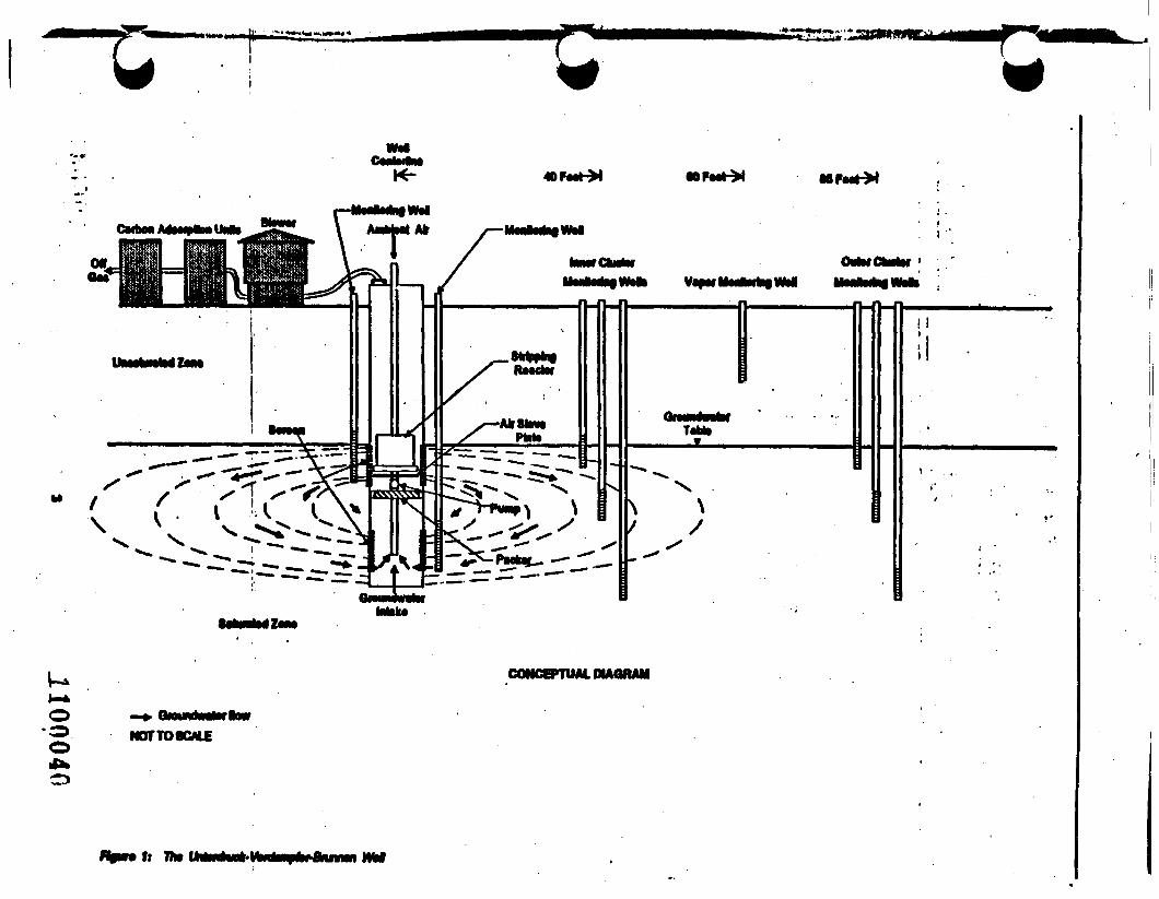
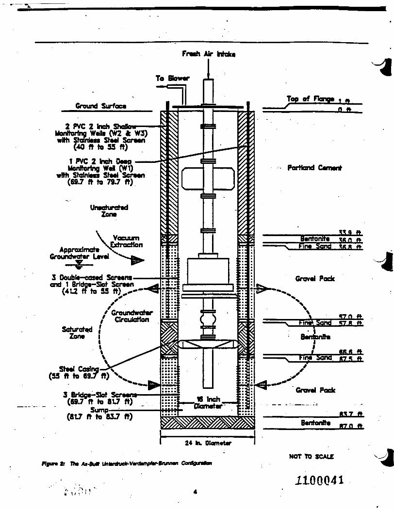
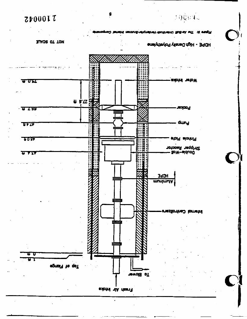
Technology DescriptionOne of tha UVB technology designs is an In situgroundwatar remediation technology that combines air-lift pumping and air stripping to ramova VOCs fromgroundwatar. A property installed UVB system consistsof a single wad with two hydrauBcafly aaparatad screenedintervale installed within a single permeable zone(Figures 1, 2 and 3). Tha air-lift pumping occurs Inresponse to negative pressure Introduced at tha weBhaadby a blower. This blower creates a vacuum that drawswater into the weD through the lower screened portion ofthewel. Simultaneously, air stamping occurs as ambientair (also flowing in response to the vacuum) to introducedthrough a slave plate located within tha upper screenedsection of the well, causing air bubbles to form in thewater pulled into thewel. The rising air bubbles providetha aJr-llft pump affect that moves water towvd the top ofthe well and draws water into tha lower scr» anad sectionof thewel. This pumping affect to supplemented by asubmersible pump that ensures that water flows frombottom to top In thewel. As the air bubbles rise throughthe water column, volatile compounds are transferred fromthe aqueoustothegaseous phase. The rising air transportsvolatile compounds to the top of thewel casing, wherethey are removed by the blower. The blower effluent totreated before discharge using a carbon adsorption urtL
Tha transfer of volatile compounds to further enhanced-by a stripping reactor located immediately above the stoveplata. Tha stripping reactor consists of a fluted andchannelized column that facilitates tha transfer of voiattocompounds to tha gas phase by increasing tha contacttime between tha two phases and by minimizing thecoalescence of air bubbles. The overall stripping zona oftha UVB system extends from the stove plate to tha top
1100039
•OFMt-X
TaM**
\/
CONCEPTUAL OIMUMII
ook.o
NOT TO SOLE
ft
Frwh Air Hdca
To Bbwar
Ground Surfoea
2 PVC 2 Inch ShoBowMenftorfhg Wads (W2 ft W3)wfth Stoiraass Stad Scraan
(40 ft to 55 ft)
1 PVC 2 tneh DMOMonfforing Wtl (W1)
wfth StdnlMS StMl SCTMH(69.7 ft to 79 J ft)
UraoturetadZona
ApprozlmetaGroundwotar Lavai
3 Ooubto-casad Send 1 Bridca-Sot Seraan
(412 ft to 55 ft) --1
Sfaal Cosing(55 ft to 69T ft) V
3 Bridga-Sot __.(69.7 ft to 817 ft)
Sump(817 ft to 83J ft)
24 hk Dlamtitr
Rgun Ir Tte At-Bu* Un*r*ve*-V*dfmp»*Bnjnn*i ConOguntanNOT TO SCALE
1100041
«u
nvos oi ION O3dOH
C.I
of the water column. To maximize volatilization in thestripping zone, the sieve plate and stripping reactor arepositioned at a depth that optimizes the reach of thestripping zone and the volume of air flow into the system.The down-wen components of the UVB system have beendesigned wtth leveling ballast that allows the system tobe free floating. This feature allows the system tocompensate for fluctuations In groundwater elevationduring operation and, thereby, maintain maximumvolatilization.
Once the upward stream of water leaves the strippingreactot, the water falls back through the well casing andreturns to the aquifer through the upper wef screen. Thisreturn flow to the aquifer, coupled wtth inflow at the we!bottom, circulates groundwater around the UVBweR. Theextent of the circulation pattern to known as the radius ofcirculation eel, which determines the volume of wateraffected by the UVB system.
The radius of circulation eel and the shape of the circulationpattern are directly related to the properties of the aquifer.The circulation pattern is further modified by naturalgroundwater flow that skews the pattern in thedowngradtont direction. Numerical simulations of the UVBoperation indfcates that the radius of circulation eel islargely condoled by anisotropy (horizontal [Kh] and vertical[Kv] hydraulic conductivity), heterogeneity, aquiferthickness and, to a lesser extent, wefl design. In general,changes that favor horizontal flow over vertical ftow suchas a small ratio of screen length to aquifer thickness,anisotropy, horizontal heterogeneities such as lowpermeability layers, or increased aquifer thickness wNincrease the radius of circulation eel. As a general rule,the developer estimates the system's radius of circulationcell to be approximately 2.5 times the distance betweenthe upper, and lower screen Intervals.
Groundwater wfcWn the radius of circulation eel includesboth treated and untreated water. A portion of the treatedwater discharged to the upper screen is recaptured withinthe circulation eel. Treated water not captured by thesystem leaves the circulation cell in the downgradientdirection. The percentage of treated water recycled withinthe UVB system 0EG estimates that It can be up to 90percent) is related to the radius of circulation eel and is afunction of the ratio of Kh/Kv. The larger the radius ofcirculation eel and the larger the Kh to Kv ratio values,the smaller the percentage of recycled water for a givenaquifer. The recycled treated water dilutes influentcontaminant concentrations.
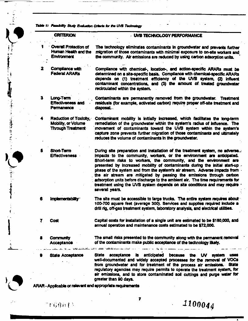
Technology ApplicabilityThe UVB technology's appficabfllty was evaluated basedon the nine criteria used for decision making in theSuperfund feasibility study process. Results of the
evaluation are surnmarized In labJe 1. In general, the UVBtechnology is applicable for treatment of dissolved phase ^volatile compounds in groundwater. The developer claims Jthat other UVB system configurations aOow for treatment '-^^Mof semi- and non-volatile contaminants and nitrates. InaddUon, the chemical and physical dynamics establishedby the redrculation of treated water make this technologysuited for remediation of contaminant source areas. Thetechnology employs readily available equipment andmaterials and the material handUng requirements and sitesupport requirements are minimal
The UVB system demonstrated for the SITE program wasdesigned to remove VOCs from the groundwater, inparticular TCE and 1,1-dichloroethene (DOE). Thedeveloper claims that the technology can also dean upaquifers contaminated with other organic compounds,Including volatile and semivolatile hydrocarbons.According to the developer, the UVB technology in somecases is also capable of simultaneous recovery of solgas from the vadose zone and treatment of contaminatedgroundwater from the aquifer as a resutt of the in situvacuum. For sol gas recovery, the upper screened portionof the UVB wel is completed from below the water tableto above the capMary zone. Although the developer claimsthat the UVB technology reduces VOCs from soil gas inthe vadose zone, the technology was evaluated only forIs effects in the saturated zone.
Technology LimitationsThe UVB technology has Imitations in areas wtth veryshallow groundwater (less than 5 ft). In such areas, Imay be difficult to establish a stripping zone long enoughto remove contaminants from the aqueous phase. Thetechnology has further Imitations in thin aquifers (lessthan 10 ft.); the saturated zone must be of sufficientthickness to allow proper instaiation of the system. Inaddition, the thickness of the saturated zone affects theradius of emulation cell; the smaller the aquiferthicknesses, the smaller the radius of circulation ceL
The majority of water being drawn from the aquifer intothe lower screen section is treated water relnfltrated fromthe upper section. This recirculation of cleaned watersignificantly decreases the contaminant levels In the watertreated by the system. As the UVB system continues tooperate, the circulation eel grows untfl a steady state isreached. As the circulation cell grows, the amount ofrecirculated water Increases causing a further decreaseof contaminant levels In the water treated by the system.
High concentrations of volatile compounds may requiremore than one pass through the system to achieveremediation goals. This may initially be a problem sincea portion of the treated water b not captured by the systemand leaves the drcutaflon eel h the downgradient dtacboa
J100043
AM»f; Stud? fioJbrtbn CHtofc lor tfw UVB Technology
CRITERION UVB TECHNOLOGY PERFORMANCE
Overall Protection of The technology eliminates contaminants In groundwater and prevents furtherHuman Health and the migration of those contaminants with minimal exposure to on-stte workers andEnvironment the community. Air emissions are reduced by using carbon adsorption units.
I
Compliance withFederal ARARs
3 Long-TecmEffectiveness and <Permanence .
4 Reduction of Toxldty,Mobility, or VolumeThrough Treatment
Compliance with chemical-, location-, and action-specific ARARs must bedetermined on a site-specfflc basis. Compliance with chemical-specific ARARsdepends on (1) treatment efficiency of the UVB system, (2) influentcontaminant concentrations, and (3) the amount of treated graundwaterredrculated within the system.
Contaminants are permanently removed from the groundwater. Treatmentresiduals (for example, activated carbon) require proper off-site treatment anddisposal... ' .
Contaminant mobility is initially increased, which facilitates the long-termremediation of the groundwater within the system's radius of influence. The
movement of contaminants toward the UVB system within the system'scapture zone prevents further migration of those contaminants and uMmatelyreduces the volume of contaminants in the groundwater.
5 Short-TermEffectiveness
During site preparation and installation of the treatment system, no adverse-impacts to the community, workers, or the environment are anticipated.Short-term risks to workers, the community, and the environment arepresented by increased mobility of contaminants during the initial start-up -phase of the system and from the system's air stream. Adverse impacts fromthe air stream are mitigated by passing the emissions through carbonadsorption units before discharge to the ambient air. The time requirements fortreatment using the UVB system depends on site conditions and may require -several years.
The site must be accessible to large trucks. The entire system requires about100-700 square feet (average 300). Services and supplies required include adrill rig, off-gas treatment system, laboratory analysis, and electrical utBffies.
7 Cost Capital costs for installation of a single unit are estimated to be $180.000. andannual operation and maintenance costs estimated to be $72.000.
8 CommunityAcceptance
The smaP risks presented to the community along with the permanent removalof the contaminants make public acceptance of the technology l&ely.
9 State Acceptance State acceptance is anticipated because the UV system uses. . well-documented and widely accepted processes for the removal of VOCs
from groundwater and for treatment of the process air emissions. Stateregulatory agencies may require permits to operate the treatment system, forair emissions, and to store contaminated soil cuttings and purge water forgreater than 90 days.
ARAR -Appicable or relevant and appropriate requirements
J100044
However, as the UVB circulation cell is established, theinfluent concentrations should be diluted to below levelsrequiring more than one pass, thereby limiting the potentialmigration of contaminants above target concentrationsfrom the system.
Process ResidualsThe materials handling requirements for the UVB systeminclude managing spent granular activated carbon, drillingwastes, purge water, and decontamination wastergenerated during installation, operation, and montoring ofthe treatment system. Spent carbon generated duringtreatment of the system air effluent wtt either be disposedof or regenerated by the carbon vendor. The driing wastesare produced during installation of the system well. Thedrilling waste can be managed either in 55-gallon drumsor in roll-off type debris bins. Disposal options for thiswaste depend on toco' requirements and on the presenceor absence of contaminants. The options may range fromon-site disposal to disposal in a hazardous waste orcommercial waste landfil.
Purge water is generated during development and samplingof the groundwater monitoring weds. Purge water can bemanaged in 55-gallon drums. Disposal options againdepend on local restrictions and on the presence orabsence of contaminants. Options range from surfacedischarge through a National Pollutant DischargeElimination System (NPDES) outfall, to disposal througha PubSdy Qvwwd Treatment Works (POTW), to treatmentand disposal at a permitted hazardous waste fadBty.
Decontamination wastes are generated during instalationand sampling activities. Decontamination wastesgenerated during installation include decontamination waterand may include a decontamination pad for the drit rig.The solid decontamination wastes can be managed in rol-off type debris boxes, and the liquid wastes can bemanaged in 55-gallon drums. Disposal options are similarto those for drilling wastes and purge water.
Site Requirements
A UVB treatment system consists of several majorcomponents: an 8,10,16, or 24-inch dual screen weH,well packer, submersible pump, sieve plate, strippingreactor, blower, and carbon fBterunte. A drill rig is requiredto install the system wei. Once the well has beencompleted, the treatment system can be operational wdthh1 day tf aH necessary equipment, utilities, and supplies .are available.The sfte support requirements needed for the UVB systemare space to set up the carbon adsorption units and
electricity. The system requires standard 120/240 vots •(200 amperes). An electrical pole, • 480-vol transformer, i§>and electrical hookup between the supply Ines, pole, and •the UVB treatmentsystem are necessary to supply power. —-41The space requirements for the above-ground componentsof the UVB system Including me UVB system wed, off.gas treatment units, blower, and piping used during theSITE demonstration are approximately 500 square feetOther requirements for instalation and routine monitoringof the system include access roads for equipmenttransport, security fencing, and decontamination fluids fordrilling and sampling.
Performance DataThe SITE demonstration for the UVB technology wasdesigned with three primary and seven secondaryobjectives to provide potential users of the technologywith the necessary information to assess the applicabilityof the UVB system ait other contaminated sites.Demonstration program objectives were achieved bycollecting groundwater and soH gas samples, as wen asUVB system process air stream samples cvera 12-monthperiod. To meet the objectives, data were collected inthree phases: baseline sampling, long-term sampling, anddye trace sampling. Baseline and long-term samplingincluded the coBectton of groundwater samples from eightmonitoring wells, a soil gas sample from the soH vapor ^monitoring wei, and air samples from ther ttvee UVB |process air streams both before UVB system startup and Mmonthly thereafter. In addition, a dye trace study was "~~"conducted to evaluate the system's radius of circulationcell. This study included the introduction of fluorescentdye into the groundwater and the subsequent monitoringof 13 groundwater wefls for the presena week over a 4-month period
»of dye three times
The conclusions of the UVB SITE demonstration at MarchAFB are presented below by project objective.
Primary Objectives:
PI r^termine the concentration ta which the UVBtechnology reduces TCEandDCElngruuitiHaterdischarged from the treatment system.
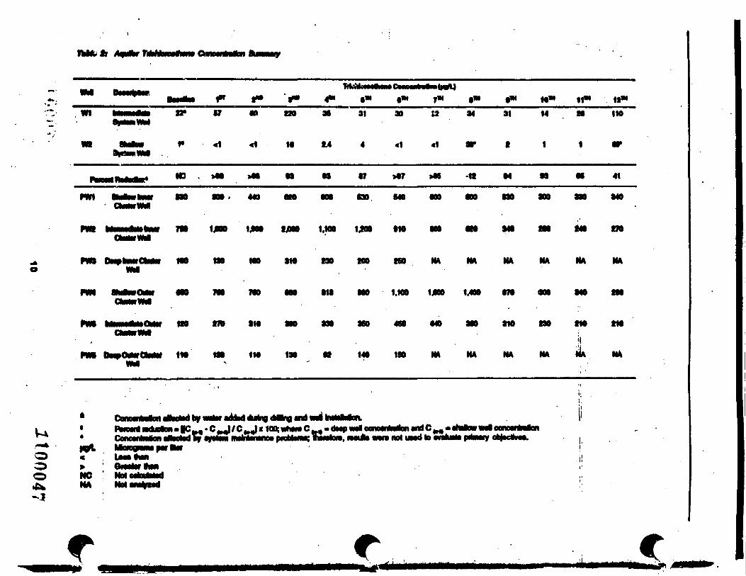
The UVB effectively removed target compounds from thegroundwater as indicated by the analytical resultspresented in Table 2. During the demonstration. TCEconcentrations in samples from the Influent well rangedfrom 14 ;/g/L to 220 //g/L with an arithmetic mean ofapproximately 56 pg/L The UVB system reduced TCEi the groundwater discharged from the treatment system
to below 5/jg/L in nine out of the 10 monthly monitoring J.2100045
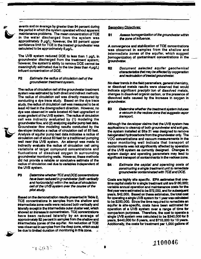
events and on average by greater than 94 percent duringthe period in which the system operated without apparentmaintenance problems. The mean concentration of TCEIn the water discharged from the system wasapproximately 3 u&L; however, the 95 percent upperconfidence limit for TCE in the treated groundwater wascalculated to be approximately 6 ug/L.
The UVB system reduced DCE to less than 1 pg/L ingroundwater discharged from the treatment system;
•however, the system's ability to remove DCE cannot bemeaningfully estimated due to the low (less than 4//g/L)influent concentration of DCE.
P2 Estimate the radius of circulation cell of thegroundwater treatment system.
The radius of circulation cell of the groundwater treatmentsystem was estimated by both direct and indirect methods.The radius of circulation cell was directly measured byconducting a dye trace study. Based on the dye tracestudy, the radius of circulation cell was measured to be atleast 40 feet in the downgradient direction. However, nodye was observed in wells located 40 feet upgradient orcross gradient of the UVB system. The radius of circulationcell was indirectly evaluated by (1) modeling thegroundwater flow, and (2) analyzing aquifer pump test dataGroundwater flow modeling results conducted by thedeveloper indicate a radius of circulation cell of 83 feet.Analysis of aquifer pump test data indicates a radius ofcirculation cell of about 60 feet for a tradittoned pumpingwell near this UVB system. An attempt was made toindirectly evaluate the radius of circulation cell usingvariations of target compound concentrations andfluctuations of dissolved oxygen in surroundinggroundwater monitoring wells. However, these methodsdid not provide a reliable or conclusive estimate of theradius of circulation cell due to variables independent ofthe UVB system.
P3 Determine whether TCE and DCE t Ttrationshave been reduced in groundwater (bath verticallyand horizontally) within the radius of circulationcell of the UVB system over the course of thepilot study.
Based on the demonstration results presented in Table 2,TCE concentrations in samples from the shallow andintermediate zone wells were reduced both vertically andlaterally except in the intermediate outer duster well, whichshowed an increase in concentration. TCE concentrationshave been reduced laterally by an average ofapproximately 52 percent In samples from the shalow andintermediate zones of the aquifer. No reduction of TCEwas observed in samples from the deep zone, which ooukfbe due to limited duration of monitoring in this zone. -
Secondary Objectives:
81 Assess homogenization of the groundwater withinthe zone of influence.
A convergence and stabilization of TCE concentrationswas observed in samples from the shallow andintermediate zones of the aquifer, which suggestjtomogenizatiorj of contaminant concentrations in thegroundwatec
82 Document selected aquifer geochemicalcharacteristics that may be affected by oxygenationand ndrculation of treated groundwater.
No dear trends in the field parameters, general chemistry,or dissolved metals results were observed that wouldindicate significant precipitr lion of dissolved metals,changes in dissolved organic carbon, or the presence ofdissolved salts caused by the increase in oxygen ingroundwater.
83 Veterrnhe whether the treatment system inducesa vacuum in the vadose zone that suggests vaportransport
Although the developer claims that the UVB system hasapplications to cleanup of both groundwater and soil gas,trie system installed at Site 31 was designed to removehalogenated hydrocarbons from the groundwater only. TheVOC concentrations and vacuum measurements in thevapor monitoring well indicate that transport ofcontaminants was not significantly affected by operationof the UVB system as currently designed. Changes insystem design and operating parameters may lead tosignificant transport of contaminants in the vadose zone.
84 Estimate the capital and operating costs ofconstructing a single treatment unit to remediateyroundwater contaminated with TCE and DCE.
Costs are highly site specific. EPA estimates that one-time caplal costs for a single treatment unit are $180,000;variable annual operation and maintenance costs for thefirst year were estimated to be $72.000, and for subsequentyears, $42,000. Based on these estimates, the total costfor operating a single UVB system for 1 year was calculatedto be $260,000. Since the time required to remediate anaquifer is site-specific, costs have been estimated foroperation of a UVB system over a range of time forcomparison purposes. Therefore, the cost to operate asingle UVB system was calculated to be $340,000 for 3years, $440,000 for 5 years, and $710,000 for 10 years.Additionally, the costs for treatment per 1,000 gallons of
.2100046
fhftfetr
KitfU|W f W f M (M 10* It*
120 31 14 110
>*? 41
000 . 449 OM C30 640 NO
7W 1*00 1jM» IJ000 1.MO 1JOO
no in 3M MO HO MA MA NA MA
000 010 MO 1.
no no oto
1M 130
UNO 1 00 070 900
in MA NA
140
MO 00
NA
iiH* NA
mfCM«nrtUMdtomlu
oo NO Not
r c
c
jroundwater were estimated to be $260 for 1 year, $110for 3 years, $88 for 5 years, and $71 for 10 years. Thecost of treatment per 1,000 gallons refers to the amountof groundwater pumped through the system. Potentialusers of the treatment technology should be aware thattypically 60 to 90 percent of the water pumped throughthe system is redrculated water. A more detailed document,the Innovative Technology Evaluation Report (ITER)contains Information on the assumption for these costfigures.
85 Document pre- and post-treatment off-gas volatileorganic contaminant levels..
The results from air monitoring of the UVB treatmentsystem indicated that low concentrations of TCE wereremoved from the groundwater. TCE concentrationsreduced by the UVB system correlate to trends observedin target compound concentrations in the tamer clustermonitoring wells (that is, increasing concentration fromthe baseline event to the third monthly monitoring eventwith a subsequent decrease in concentrations).
86 Document system operating parameters.
The temperature of the internal monitoring ports rangedfrom 18.5 to 44.7 degrees Celsius; the relative humidityranged from 27 to 100 percent; the vacuum pressureranged from 13.81 to 15.03 pounds per square inchabsolute; the air flow ranged from 100 to 898 standardcubic feet per minute; the air velocity ranged from 1,109to 9,999 feet per minute; and the discharge through theUVB system was estimated by the developer to beapproximately 22 gallons per minute.
87 Evaluate the presence of aerobic biologicalactivity In the saturated and vadose zones.
Carbon dioxide concentrations measured hi the vapormonitoring well indicate that carbon dtodde has increasedby more than 2 percent since baseline monitoring. Severalfluctuations in O2 level were observed; however, therewas no evidence of a downward trend of theseconcentrations. The minor changes in CO2 and O2measured suggest that bioacth/ity in the soil andgroundwater was not significantly enhanced by operationof the UVB system.
Additionally, CO2 concentrations measured at the UVBsystem's intake and after the blower reveal minorfluctuations of relative CO2 concentration. These resultsalso suggest that bioactivlty due to increased dissolvedoxygen levels in the groundwater was not significantlyenhanced by operation of the UVB system.
Technology Status
Since Its introduction in 1986, the UVB technology hasbeen applied at some 80 sites in Europe. No U.S.installation of a UVB system has required an NPDESpermit to date. A UVB system was first installed at aU.S. site in September 1992; currently, there are 22 UVBsystems operating in eight states.
A more detailed document, the ITER, contains more-Information on this documentation, the developer has
provided four select case studies that document operationof the UVB system at stes in the U.S. and Germany. Twoof the cases are from sites in Germany and involve theremediation of chlorinated hydrocarbons (TCE, 1,1,1-trichtoroetnane, and dichloromethane) in the groundwater.The two cases from the U.S. document the remediationof groundwater contaminated with benzene, toluene,ethylbenzene, and xylene at an underground storage tanksite in Troutman, North Carolina, arJ Weston'sinterpretation of the data collected during but independentof this SITE demonstration.
Sources of Further InformationFor further information, contact
U.S. EPA Project Manager.Ms. MicheHe SimonU.S. Environmental Protection Agency26 West Martin Luther King DnVeCincinnati, OH 45268513-569-7469FAX- 513-569-7676
Technology Devetopen
IEG TECHNOLOGIES CORPORATIONOR. ERIC KLINGEL5015 0 M T HARRIS BLVD.CHARLOTTE, HC 28269(704) 599 4818
_J7fU) 599 4815 -_F«X_March AFB Demonstration Partner.
RoyF.Weston.lnc.Mr. Jeff Bannon14724 Venture Blvd., SuRe 1000Sherman Oaks, CA 91403(818)971-4900Fax (818)971-4901
11 1100048
United StatMEnvironmental Protection
-T Nrttonrt Rbfc Mgiagement nwareh Laboratory (0-72):., ~'iir*ialL OH 46268-<-, •
.• •• PwiaRytotPrtwitoUM : •$300 ' .
»-*O
oCO
nrte fcii iiirmiMV rtungMi an t» batoa Mid.
• you do mi «* to mo*w tm» nputo CHECK HCTC D ;itaiMh. or cot* •* eoww. and nun to ft*upper MM»nd oomtr.
BULK RATEPOSTAGE & FEES PAID
EPAPERMTTNo.0-35