epicyclic gearing and the antikythera mechanism pt 1 a.h. ma
TRANSCRIPT

270ANTIQUARIAN HOROLOGY
THE oldest known use of toothed gearing,the Antikythera Mechanism, is preservedin the National Archaeological Museum
in Athens.1 It became widely known throughthe work of the late Professor Derek Price,whose monograph Gears from the Greeks remainsthe best general introduction to the subject.2
Price suggested that the Mechanism, datingfrom the first century BC, demonstrated theexistence of a highly-developed Hellenistictradition of geared instruments which,transmitted to and preserved in Arabic culture,thence influenced the development of theWestern European tradition of clockwork.
This argument remains unchallenged. I havemyself contributed to work that provides goodevidence for the earlier transmission, fromHellenistic to Arabic culture.3 On the otherhand, a careful reading of his account showedthat Price’s understanding of the AntikytheraMechanism itself was flawed. This led the lateProfessor Allan Bromley and myself to make anew, more detailed, survey of the originalfragments.4,5 I am now developing a new
reconstruction on the basis of theseobservations, which differs in many importantrespects from others which are all based onPrice’s observations.
I have published a partial reconstruction,demonstrating that one face of the instrument,which Price called the ‘front’, may be restoredas a planetarium.6 The motions in longitude ofthe Sun, the Moon and the five planets knownin antiquity are shown by seven hands, allcontrolled by epicyclic mechanism, moving overa Zodiac circle. An eighth hand shows the dateon a concentric calendar ring. This schemeaccounts better and more fully for someprominent features found on the ‘front’ face ofthe original fragment A (Fig. 1) than does anyother reconstruction known to me, and it isconsonant with the reports of planetaria that arefound in literature contemporary with theAntikythera Mechanism.7
Anticipating doubt that my reconstructionmight be thought practicable, I made a workingmodel to illustrate it.8 Figure 2 shows theexternal appearance of the model in its present
EPICYCLIC GEARINGAND THE ANTIKYTHERA MECHANISM
PART I
by M. T. Wright
1. Inventory Number X.15087.2. D. J. de S. Price: ‘Gears from the Greeks’, Transactions of the American Philosophical Society, Vol. 64 No. 7 (1974).
Reprinted as an independent monograph, (New York: Science History Publications, 1975). Also published in Greekby Technical Museum of Thessaloniki (1995).
3. J. V. Field & M. T. Wright, ‘Gears from the Byzantines: a portable sundial with calendrical gearing’, Annals of Science45 (1985), 87-138; also reprinted in J. V. Field, D. R. Hill & M. T. Wright, Byzantine and Arabic MathematicalGearing, (London: Science Museum, 1985).
4. Allan George Bromley, formerly Associate Professor in the Basser Department of Computer Science, University ofSydney, died on 16th August 2002, aged fifty-five.
5. A. G. Bromley, ‘Observations of the Antikythera Mechanism’, Antiquarian Horology, Vol. 18 No. 6 (Summer 1990),641-652. M. T. Wright, A. G. Bromley & H. Magou, ‘Simple X-ray Tomography and the Antikythera Mechanism’,PACT 45, (1995). M. T. Wright & A. G. Bromley, ‘Current Work on the Antikythera Mechanism’, proc. conf. AncientGreek Technology (Thessaloniki: Technical Museum of Thessaloniki, 1997).
6. The underlying theoretical and historical considerations are covered in two papers: M. T. Wright & A. G. Bromley,‘Towards a New Reconstruction of the Antikythera Mechanism’, proc. conference Extraordinary Machines and Structuresin Antiquity, Ancient Olympia (August 2001), (Athens, Kaktos, forthcoming); and M. T. Wright, ‘In the steps of theMaster Mechanic’, proc. conference Ancient Greece and the Modern World, Ancient Olympia, (July 2002), forthcoming.
7. See Price (1974), note 2.8. The model, in an early form, is described and illustrated in: M. T. Wright, ‘A Planetarium Display for the Antikythera
Mechanism’, Horological Journal, Vol. 144 No. 5 (May 2002), 169-173, and Vol. 144 No. 6 (June 2002), 193. In aslightly more developed form, it has now stood the test of being displayed to the Athenian public, who were free towork it, in the exhibition Ancient Technology at Technopolis, September-October 2002.
� � �

271 MARCH 2003
Fig. 2. Antikythera Mechanism, reconstruction of the frontdial by M. T. Wright.
Fig. 3. Model as Fig. 2, partially disassembled to show itscorrespondence to the original, Fig. 1.
state and Fig. 3 shows it partially disassembledso that its relationship to the original, seen inFig. 1, is clear. In making this model I took careto imitate details seen in the original fragmentsand to make my conjectural restorations in asimilar style. For the most part, I used onlysimple hand tools. The only important respectin which I used equipment not available inantiquity was in cutting the wheels, for whichI saved time by using ‘modern’ (1887) dividingapparatus. I have, however, previouslydemonstrated that there is no difficulty in
Fig. 1. Antikythera Mechanism, fragment AAAAA, front.Approximately 35% actual size.
dividing the circle into any desired number ofparts and cutting teeth, to a sufficient degree ofprecision, using only very simple tools.9
In its present state my model contains forty-one wheels beyond those for which directevidence is found in the original fragments, allserving the planetarium dial. Most of them arefound within the five separate epicyclicassemblies that give motion to the Sun, Moonand planet hands, and the others drive the threeassemblies for the superior planets. Thisrepresents, roughly speaking, a doubling of thenumber of wheels in the whole instrument. Themechanism is not, however, made much moreintricate than was previously supposed; rather,it is made more extensive. In particular, theepicyclic assemblies that I introduce arecomparable with the one of which about halfsurvives on the rear face of the original fragmentA (Fig. 4). According to Price, this assemblyfunctioned as a differential gear.
The identification of this sophisticatedensemble within the remains of the earliestgeared mechanism known has naturally calledforth much speculation and comment. While itprovides me with a precedent for the epicyclicclusters which, in my reconstruction, furnish themotion of the pointers for the Sun, Moon andplanets according to epicyclic models, I reject arecent suggestion that it might itself have servedas part of such a model.10 Firstly, I cannot see
9. M. T. Wright, ‘Rational and Irrational Reconstruction: the London Byzantine Sundial-Calendar and the Early Historyof Geared Mechanisms’, History of Technology, Vol. 12 (1990), 65-102.
10. T. Freeth, ‘The Antikythera Mechanism’, Mediterranean Archaeology & Archaeometry, Vol. 2 Nos 1 & 2 (June &December 2002), 21-35 & 45-58.

272ANTIQUARIAN HOROLOGY
how to interpret the visible detail in this way.Secondly, it is clear, both from directobservation and from radiographs, that theepicyclic assembly has not been significantlydisplaced from its intended position withrespect to the frame plate (Price’s ‘base plate’)on which, along with most of the other mobiles,it was planted; it lies between this plate and theback dial plate, and it is not concentric with anyof the dial systems of the instrument. Thirdly,the function of the surviving gearing of thefront dial, and its connection to the epicyclicgear (which will be discussed below), both seemsufficiently clear to confirm that this epicyclicplatform cannot have turned at a rateappropriate to the realisation of any epicyclicastronomical model.
In fact, my reconstruction of the front dialdepends crucially on the observation that the
Fig. 5. Diagram of the gearing system according to D. J. de S. Price (note 2), reproduced by permission of The AmericanPhilosophical Society.
Fig. 4. Antikythera Mechanism, fragment AAAAA, back.Approximately 35% actual size.
273 MARCH 2003
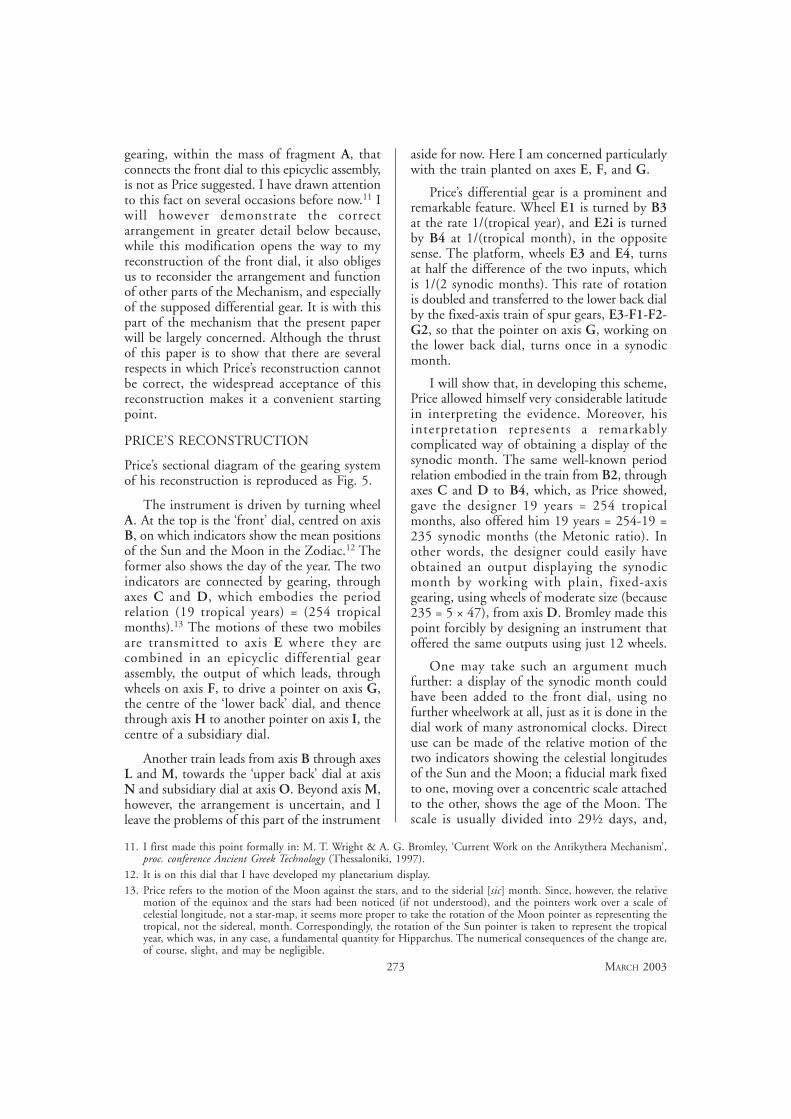
gearing, within the mass of fragment A, thatconnects the front dial to this epicyclic assembly,is not as Price suggested. I have drawn attentionto this fact on several occasions before now.11 Iwill however demonstrate the correctarrangement in greater detail below because,while this modification opens the way to myreconstruction of the front dial, it also obligesus to reconsider the arrangement and functionof other parts of the Mechanism, and especiallyof the supposed differential gear. It is with thispart of the mechanism that the present paperwill be largely concerned. Although the thrustof this paper is to show that there are severalrespects in which Price’s reconstruction cannotbe correct, the widespread acceptance of thisreconstruction makes it a convenient startingpoint.
PRICE’S RECONSTRUCTION
Price’s sectional diagram of the gearing systemof his reconstruction is reproduced as Fig. 5.
The instrument is driven by turning wheelA. At the top is the ‘front’ dial, centred on axisB, on which indicators show the mean positionsof the Sun and the Moon in the Zodiac.12 Theformer also shows the day of the year. The twoindicators are connected by gearing, throughaxes C and D, which embodies the periodrelation (19 tropical years) = (254 tropicalmonths).13 The motions of these two mobilesare transmitted to axis E where they arecombined in an epicyclic differential gearassembly, the output of which leads, throughwheels on axis F, to drive a pointer on axis G,the centre of the ‘lower back’ dial, and thencethrough axis H to another pointer on axis I, thecentre of a subsidiary dial.
Another train leads from axis B through axesL and M, towards the ‘upper back’ dial at axisN and subsidiary dial at axis O. Beyond axis M,however, the arrangement is uncertain, and Ileave the problems of this part of the instrument
aside for now. Here I am concerned particularlywith the train planted on axes E, F, and G.
Price’s differential gear is a prominent andremarkable feature. Wheel E1 is turned by B3at the rate 1/(tropical year), and E2i is turnedby B4 at 1/(tropical month), in the oppositesense. The platform, wheels E3 and E4, turnsat half the difference of the two inputs, whichis 1/(2 synodic months). This rate of rotationis doubled and transferred to the lower back dialby the fixed-axis train of spur gears, E3-F1-F2-G2, so that the pointer on axis G, working onthe lower back dial, turns once in a synodicmonth.
I will show that, in developing this scheme,Price allowed himself very considerable latitudein interpreting the evidence. Moreover, hisinterpretation represents a remarkablycomplicated way of obtaining a display of thesynodic month. The same well-known periodrelation embodied in the train from B2, throughaxes C and D to B4, which, as Price showed,gave the designer 19 years = 254 tropicalmonths, also offered him 19 years = 254-19 =235 synodic months (the Metonic ratio). Inother words, the designer could easily haveobtained an output displaying the synodicmonth by working with plain, fixed-axisgearing, using wheels of moderate size (because235 = 5 × 47), from axis D. Bromley made thispoint forcibly by designing an instrument thatoffered the same outputs using just 12 wheels.
One may take such an argument muchfurther: a display of the synodic month couldhave been added to the front dial, using nofurther wheelwork at all, just as it is done in thedial work of many astronomical clocks. Directuse can be made of the relative motion of thetwo indicators showing the celestial longitudesof the Sun and the Moon; a fiducial mark fixedto one, moving over a concentric scale attachedto the other, shows the age of the Moon. Thescale is usually divided into 29½ days, and,
11. I first made this point formally in: M. T. Wright & A. G. Bromley, ‘Current Work on the Antikythera Mechanism’,proc. conference Ancient Greek Technology (Thessaloniki, 1997).
12. It is on this dial that I have developed my planetarium display.13. Price refers to the motion of the Moon against the stars, and to the siderial [sic] month. Since, however, the relative
motion of the equinox and the stars had been noticed (if not understood), and the pointers work over a scale ofcelestial longitude, not a star-map, it seems more proper to take the rotation of the Moon pointer as representing thetropical, not the sidereal, month. Correspondingly, the rotation of the Sun pointer is taken to represent the tropicalyear, which was, in any case, a fundamental quantity for Hipparchus. The numerical consequences of the change are,of course, slight, and may be negligible.

274ANTIQUARIAN HOROLOGY
although this is a crude approximation, no erroraccumulates from month to month.14 Arepresentation of the phases of the Moon isoften achieved by fitting a concentric disc,having an eccentric circular aperture, to theouter of the two indicators, through which,usually, one sees a portion of a contrastingeccentric zone on a further disc attached to theother indicator. Occasionally, the openingcontains a rotating Moon ball.15 It is possiblethat the ‘drumlike component’ reported by Price(note 2, 20), which I measure as 62-63 mm. indiameter, may be the relic of some such displayfeature, but I have not so far developed a whollysatisfactory reconstruction of it.16 Such anarrangement could be applied equally well eitherto Price’s front dial display or to mine. Appliedto my reconstruction which models the motionsof the Sun and Moon according to the theoriesof Hipparchus, this display would give asuperior performance to any that is based merelyon the mean motions of the Sun and Moon.
Of course, the fact that Price’s reconstructionachieves a display that could have been realisedby a simpler arrangement is by no means a sureindication that it is wrong. It is, in fact, notuncommon for an early essay in a developingtechnology, which the Antikythera Mechanismmight arguably be supposed to represent, to bemore complex than necessary. The contrastbetween the evident accomplishment of theexecution of the original instrument and over-complicated way in which Price’s reconstruction
achieves the supposed dial displays does,however, give one pause for thought.
Besides this, there is a practical problem withPrice’s reconstruction. The whole system isdriven from the slow-moving end of the train.17
The overall effect is of a branched step-up trainyielding ratios of roughly 12.4 : 1 and 13.4 : 1.Ordinarily this would pose no difficulty to thehorologist, but it should be remembered thatthe gears in this instrument are formed withroughly triangular teeth and that othermechanical details are naïve. In particular, theloads developed within the differential assemblylead to high friction, and a recent commentatorhas gone so far as to suggest that thearrangement is unworkable.18 This is anexaggeration, but it is commonly admitted bythose who have built models of it, even themajority in which the wheelwork has beenrealized using modern details, that it is not easyto make this arrangement work. The problemis exacerbated when the attempt is made to copythe details of the original more closely.
Bromley’s modification of Price’s schemeavoided this problem by driving the train fromgear E4, for which Price had found nopurpose.19 E4 is the rim of the relatively fast-moving epicyclic platform itself, and, worked inthis way, the instrument runs very sweetly.Bromley drove E4 through a reduction trainwhich began with a knob or winch turned(approximately) once per day, an astronomicalperiod that, he suggested, might appropriately
14. The earliest example of this device is found as an addition to a planispheric astrolabe dated to c. 1300, in the collectionof The Science Museum, London (Inventory Number 1880-32). The arrangement is now incomplete and garbled. Areconstruction is offered in J. D. North, ‘Opus quorundam rotarum mirabilium’, Physis, 8 (1966), 337-371.
15. Examples are described and illustrated in H. C. King & J. R. Millburn, Geared to the Stars (Toronto, Buffalo &London, 1978). The earliest example of any portrayal of the phases of the Moon effected by a design seen through anaperture is found in the London Byzantine Sundial-Calendar (Science Museum, London, Inventory Number 1983-1393), which came to light after this book was written. See note 3.
16. Price himself made this suggestion tentatively, before venturing as an alternative that it might have been a (folding)‘crank handle’ [sic] for working the instrument. The latter interpretation, which is certainly wrong, has unfortunatelybeen widely accepted. There is actually much detail within this structure to be explained. See Wright, Bromley &Magou (1995) and Wright & Bromley (1997), note 5.
17. This point was well expressed by Zeeman: E. C. Zeeman, ‘Gears from the Greeks’, Proceedings of the Royal Institutionof Great Britain, Vol. 58 (1986), 137-156.
18. G. White, ‘Antikythera Gearing - a different solution’, Horological Journal, Vol. 144 (October 2002), 358-363. White’smain point in this article is an attempt to rationalise the features of Price’s reconstruction by suggesting alterations toit. Unfortunately, because he relies on elements of this reconstruction that I show cannot be accepted, his ingenuityis wasted.
19. A. G. Bromley, ‘The Antikythera Mechanism’, Horological Journal, Vol. 132 No. 6 (June 1990), 412-415, and Vol.133 No. 1 (July 1990), 28-31.

275 MARCH 2003
be represented in the instrument.20 This varianthas gained some currency through beingpublished and exhibited, but it must beunderstood that Bromley developed it before hehad inspected the original fragments, and thatit was wholly conjectural. On obtaining accessto the original he tried, and failed, to find a wayin which such a driving train might have beenfitted. Furthermore, since the day is clearlyindicated on the front dial, Bromley’s argumentfor his ‘one turn per day’ input was not as strongas he claimed. Finally, I have stated, and willshow in greater detail below, that the large wheelequal in size to B1 (shown dotted and marked‘Sun Position’ in Fig. 5), which Price introducedto engage the upper limb of contrate wheel Aas a reversing arrangement, is not needed. Thisleaves no other function for wheel A than as themobile by which the instrument is driven.
Through what follows it will be foundprogressively harder to continue to accept Price’sreconstruction, or, by the same token, any otherreconstruction based on it. That is to say, allreconstructions of the Antikythera Mechanismknown to me, other than the one that I amdeveloping, must be abandoned. In particular,I show in this first part of my paper that thedifferential gear cannot have functioned as Pricesuggested, and so it is highly doubtful that thesynodic month was displayed on the lower backdial.
MODIFICATIONS TO PRICE’S SCHEME
I draw attention to wheels E2i, B4 and D2 inFig. 5, and invite comparison with the true
arrangement shown in Fig. 6. In reality, wheelD2 does not engage B4 but engages what I callwheel E7. (The rationale for the nomenclatureis explained below.) E7 lies adjacent to anotherwheel, marked in Fig. 6 as E6, which in turnengages wheel B4. These wheels are seen in theirtrue spatial relationship in my model, Fig. 7.E6, E7 and B4 each have 32 teeth. B4 and E6are larger and coarser in pitch than E7 (and, ofcourse, D2), so that E6 is overlapped by theedge of wheel D2. Readers who may hope tocheck details of the arrangement in plan, usingthe gearing diagrams given by Price (note 2, hisfigures 29 - 31), should be aware that in somerespects these drawings are seriously at variancewith reality.
The effect on the train connecting wheelsB1 and B4 is as though an idle wheel had beenintroduced at some point, so that B1 and B4now rotate in the same sense. If the rotation ofthe central arbor bearing wheel B4 still, asbefore, represents the motion of the MeanMoon, the rotation of B1 may now representthe motion of the Mean Sun, without Price’sclumsy reversing arrangement. The removal ofthe duplicate of B1, engaging the upper limbof wheel A, opened the way to my newreconstruction of the front dial.21
Were all the other connections to remainunchanged, the modification illustrated in Fig. 6would also reverse the sense of rotation of thewheels on the hollow arbor at axis E (E2i andE2ii in Fig. 5), with respect to the central arborwith wheels E1 and E5. Price’s scheme for theback would then be unworkable, because the
20. Some commentators state that Bromley’s day input is ‘exact’. However, as Bromley himself pointed out, due to theincommensurability of the day and the year, the velocity ratio of his driving train is an approximation. It follows thatthe inexactitude of this approximation must be reflected either in the value of the day or in the values of all the otherperiods displayed by the instrument. Whether or not it is proper to regard Bromley’s one-turn-per-day as exact thereforedepends on the use to which we imagine the instrument being put.
21. In this I continue to accept, at least provisionally, Price’s counts for the wheels B2, C1, C2, D1, D2 and B4. Thisleads me to agree with his conclusion as to the ratio of the periods of rotation of B2 and B4, although I prefer toexpress it as (tropical year) : (tropical month). (See note 12.)
Fig. 6. A first modification of Price’s gearing system: cf. Fig. 5.

276ANTIQUARIAN HOROLOGY
two inputs to the differential assembly wouldturn in the same sense; the rate of rotation ofthe output would accordingly be half the sum,not half the difference, of the rates of rotationof the two inputs, a quantity of no interest inthis context.
The radiographic survey that leads me toinsist on the rearrangement illustrated in Figs6 and 7 yields evidence, however, that Price’sscheme must be adjusted yet further. In placeof wheel E1 there is only a roughly circular‘button’ with no teeth, and wheel B3 cannot befound at all. There is therefore no extant secondinput to Price’s differential gear. It is possible tocontrive such an input, turning in the sense nowrequired, as a conjectural restoration. In doingso, however, we would be obliged to postulatethe loss of several wheels from the original, someof them in places from which they could notsimply have dropped out. While such losses are
conceivable, I consider them unlikely. Moreover,the change to the overall velocity ratio of thefixed-axis train following the epicyclic assembly,which, as I show below, is forced on us by arereading of the evidence, dictates that no such‘quick fix’, retaining the function of Price’sdifferential gear unaltered, can be satisfactory.
Instead, I suggest that the missing secondinput to the ‘differential gear’ may never haveexisted, that the central arbor at axis E was fixedto the base plate, and that wheel E5, mountedon it, was stationary. The epicyclic assemblywould then have functioned not as a differentialgear but as a gear train with one input and oneoutput.
This more extensive rearrangement isillustrated in a further partial revision of Price’ssectional diagram, Fig. 8. I begin by pointingout that Price was mistaken, in showing wheelson the underside of the epicyclic platform (E2ii,
Fig. 7. Model as Fig. 2, in an early experimental state. Underside, showing gears B4B4B4B4B4 (right), E6E6E6E6E6 and E7E7E7E7E7 (upper right),and D2D2D2D2D2 (left) in their correct spatial relationship. In its present state the model does not include the epicyclic platformwhich should be centred on axis EEEEE. Certain features seen in this view, which are not found in the original, are presentbecause this model was built of scrap. Aproximately 160% actual size.
wheelE6
wheelE7
wheelB4
wheelD2

277 MARCH 2003
K1 and J in Fig. 5) that are in reality foundabove. This particular error makes no differencein principle to the working of the epicyclicassembly, but in Fig. 8 the wheels, renamed E8,K3 and J2, are shown in their proper places.The other respects in which Fig. 8 differs fromFig. 5 are more important.
Price’s convenient system of nomenclature(letter for axis, number for wheel) is retained,but it is modified. The tidiest result would havebeen achieved by reallocating the numbers (suchas E1, E2, ... in the case already discussed), butthis might have led to confusion in comparingmy revised scheme with that of Price. Instead,where Price showed a wheel, the presence orfunction of which I cannot verify, I do not usethat letter/number code. Thus, I have no B3,E1 or E2. Wheels that are moved are treated inthe same way as new introductions, with a newletter/number code. Thus, Price’s wheels E2ii,J and K1 below the turntable are replaced byE8, J2 and K3 above it. Price’s E2i becomes E6.
Note that in Fig. 8 I indicate that axis J,carrying an idle wheel, is a conjecturalrestoration. Price stated as much in his text, butdid not indicate it in his diagram. The possibleimportance of this point will be seen later.
The tooth-counts of the wheels, and thequestion as to whether axis J existed at all, willbe discussed in the second part of this paper.Here I limit myself to pointing out that Price
was obliged to invent wheel K1 (for which thereis no evidence) equal to E2ii (which again doesnot exist, but which was plausible on the basisof the evidence available to him), and tooverrule the observations of the radiographerKarakalos (whose plates he used) that E5 andK2 were ‘double wheels’, probably havingunequal numbers of teeth, because he requiredequal wheels on axes E and K at each levelwithin his differential assembly. On the otherhand, in the arrangement now outlined,according to which we see this assembly as anepicyclic gear with a fixed central arbor, it wouldmake no sense to have equal wheels at bothlevels: with an idle wheel at J, the assemblywould then yield the trivial overall gear ratio of2 : 1, making its presence pointless; without theidle wheel, and with E8 and K3 engaging oneanother directly, the input would be locked.
THE EPICYCLIC TRAIN: GENERALCONSIDERATIONS
The epicyclic arrangement shown schematicallyin Fig. 8 is highly reminiscent of the trains usedin the late eighteenth century by Fr. David aSancto Cajetano, who published accountsshowing how epicyclic trains might be designedto yield desired velocity ratios that could beobtained only with difficulty, if at all, usingconventional fixed-axis gearing alone.22 Noearlier analysis of epicyclic gearing is known.23
However, several earlier examples of epicyclic
Fig. 8. A further modification of Price’s gearing system: cf. Figs 5 & 6.
22. Fr. David a S. Cajetano: Neues Rädergebäude (Vienna, 1791); Praktische Anleitung für Künstler ... (Vienna & Leipzig,1793); and Neues Rädergebäude mit Verbesserungen und Zusätzen (Vienna & Leipzig, 1793 & 1794).
23. G. White, ‘The Precise Epicyclic Gears of Fr. D a San [sic] Cajetano’, Horological Journal, Vol. 135: No. 2 (August1991), 65-68; No. 3 (September 1991), 86-89; No. 4 (October 1991), 137-140.

278ANTIQUARIAN HOROLOGY
gearing survive, besides the one considered here,and I suppose that the designer of each musthave had a sufficient understanding of, andworkable method for analysing the performanceof, what he created. Just what analysis mighthave been achieved when the AntikytheraMechanism was designed is a question for thehistorian of mathematics.
Unfortunately, what remains of the epicyclicgear within the Antikythera Mechanism is sopoorly preserved that it is difficult to reconstructit, and to explain its function on the basis ofits internal arrangement, with any degree ofcertainty. If this could be done, it might shedlight on the probable method of analysis usedin its design. Conversely, were the method ofanalysis known it might be used as a tool inreconstructing the mechanism. As it is, we cando little more than weigh probabilities, so thatthe reconstruction will remain uncertain and themethod by which it was designed a matter ofspeculation.
Detailed observations of the epicyclic gear inthe Antikythera Mechanism are reserved for thesecond part of this paper, in which I willconsider the range of possibilities for itsreconstruction and offer a tentative conclusion.Here I will show that some further progress maybe made by considering the context in which itis found.
THE FIXED-AXIS TRAIN TO THELOWER BACK DIAL
Leaving aside the uncertainties of the epicyclicgear itself, I turn my attention to the fixed-axistrain between it and the lower back dial. Thiscomprises E3 (the gear-ring on the epicyclicplatform) and the wheels on axes F, G, H andI. As elsewhere, Price had at his disposal thetooth-counts of Karakalos. He reported thembut he was particularly embarrassed by thembecause they did not yield the simple 2 : 1 ratio
between E3 and axis G that he required, asdescribed above. He therefore changed thecounts of wheels F1 and G2 by about six teethin each case, decreasing the first and increasingthe second.
A few wheels in the surviving fragments areso poorly preserved that there is greatuncertainty in counting their numbers of teeth.The wheels in this train do not, however, offerso much latitude as to justify the licence thatPrice took. I have checked the counts myselfusing my own radiographs, and I give mycounts, together with those of Karakalos andPrice, in Table 1. I list the wheels in the orderin which they appear in the train.
Of these, the count for F2 is quite securebecause its complete periphery can be seen inradiographs. The uncertainties in the numbersof teeth of the others are also strictly limited.
For example, as mentioned above, onlyabout half of E3 is present. Moreover, severalsmall pieces of the rim of this half are brokenout. On the other hand, a small piece remainsroughly opposite the centre of the preservedhalf, which provides the positions of a few teethand, more importantly, a secure means offinding the centre. The need to have a wholenumber of teeth in each interval provides apowerful constraint, and the results of repeatedtrials using various procedures are consistent.
There are sources of potential error,including possible lack of uniformity indivision, uncertainty in finding the centre, andout-of-roundness of the image of the wheel,whether through having never been circular,through damage, or through lying oblique tothe plane of the radiograph. The effect of suchfactors may be large when only a small part ofthe periphery of the wheel, all to one side of theaxis, can be traced. None of these wheels,however, seems to present extreme difficulty.
Table 1
wheel E3 F1 F2 G2 G1 H2 H1 I
Karakalos 192 54 30 54/55 20 16 60-62 60
Price 192 48 30 60 20 15 60 60
Wright 192 54 30 54 20 15/16 60 60?

279 MARCH 2003
Therefore my tabulated counts cannot be farwrong. One point that may be made firmly isthat Price’s alteration of the counts of F1 andG2, made simply to suit his scheme, is not onlyunsupported by, but is actually in conflict with,the evidence. It is clear that the overall velocityratio for this part of the train as given by Price,exactly 2, must be abandoned. With mynumbers, it becomes:
192/54 x 30/54 = 160/81 = 1.975308641
Following the uncertainty admitted byKarakalos, the velocity ratio might instead be:
192/54 x 30/55 = 64/33 = 1.93
One should consider the possibility, here aselsewhere in the mechanism, that one or morewheels could have been replaced by othershaving incorrect numbers of teeth; suchinterventions by the unintelligent repairer orwould-be improver are not unknown. In thiscase, however, in order to ‘restore’ the velocityratio that Price requires we should have toaccept that two wrong-numbered replacementshad been substituted for original wheels, andthat in both cases the change in the tooth-counts was such that some adjustment of thewheels that they engage would probably havebeen called for, in order to obtain a satisfactoryaction. Otherwise, modification of the velocityratio is plausible only if it is based on very smallvariations of the tooth-counts given above.
The velocity ratio of the fixed-axis train maynot, in itself, offer any guidance as to the overallvelocity ratio of the suggested arrangement,comprising an epicyclic train followed by thefixed-axis train. We may note, however, that thisinterim conclusion concerning the fixed-axistrain reduces still further the probability that theepicyclic assembly could have functioned as adifferential gear, as envisaged by Price. Were itto have done so, the output at the lower backdial would have had a period, corresponding to
the reduced velocity ratio, of rather more thanone synodic month, a quantity that seems to beof little significance.24
FUNCTION OF THE EPICYCLIC GEAR
I consider that the reconstruction of theepicyclic assembly as a differential gear must beabandoned. It seems less problematic to explainits presence as an attempt to derive, incombination with the fixed-axis train thatfollows it, a desired velocity ratio for which thedesigner could find no convenientapproximation using fixed-axis gearing alone.
The input to this assembly would have hada period of one tropical month, or, moreprecisely (but still provisionally), 19/254 of thetropical year. Applying again, to thisarrangement, the argument that thecorresponding period for the synodic month(19/235 of the tropical year) could readily havebeen obtained by simple means from the gearingof the front dial, it now appears yet moreimprobable that a display of the synodic monthshould have been intended at the lower backdial.
The lower back dial itself does not offer usmuch obvious help in trying to work out whatmay have been displayed on it, but it is indeedprobable that its complicated structure indicatessome more sophisticated use than a mere displayof the events of the synodic month.25 Thepresence of the subsidiary dial may, of course,offer a clue, but it will be seen by inspection ofTable 1 that the ratio between the periods of theindicators on the main and subsidiary dials isnot certainly 1 : 12 as Price suggested.
I will return to a fuller discussion of the reardials themselves later. So far as the lower backdial is concerned, this will be informed by therange of possibilities for reconstruction of theepicyclic gear, which I will discuss in the secondpart of this paper.
24. I am aware that by adopting the second velocity ratio given above (1.93) for the fixed-axis train, and retaining thefunction of the epicyclic assembly as a differential gear, one would obtain a period close to one-twelfth of a calendaryear for axis G, so that, with the 1 : 12 ratio between axes G and I suggested by Price, the indicator on the subsidiarydial would rotate with a period close to one year. This seems, however, a far-fetched justification for a scheme that ishard to support on other grounds.
25. I have pointed out that both back dials are constructed of sets of concentric rings, held together by radial bridge-pieces in such a way as to leave concentric tracks in which marker beads (like those of an abacus) or other movablepieces might have slid. See Wright & Bromley 2001, note 5.
• •
• •
• •