epifluorescent zeiss axioplan microscope instruction manual · • the zeiss axioplan...
TRANSCRIPT

Epifluorescent Axioplan Michelle Hubbard
1
Epifluorescent Zeiss Axioplan Microscope Instruction Manual
We are currently using the compound microscope in the confocal lab (room 024) which is equipped for transmitted light and epifluorescence microscopy. Various parts of the system are indicated in the following illustrations.
Figure 1. Overview of Axioplan Epifluorescent microscope anatomy

Epifluorescent Axioplan Michelle Hubbard
2
Figure 2. Side view of Axioplan Epifluorescent microscope anatomy
Epifluorescent Axioplan Michelle Hubbard
3
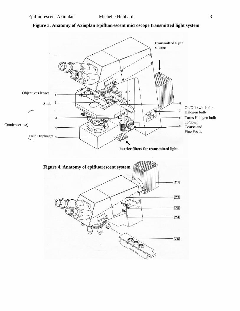
Figure 3. Anatomy of Axioplan Epifluorescent microscope transmitted light system
Figure 4. Anatomy of epifluorescent system
Objectives lenses
Slide
Field Diaphragm
On/Off switch for Halogen bulb Turns Halogen bulb up/down Condenser Coarse and Fine Focus

Epifluorescent Axioplan Michelle Hubbard
4
Transmitted light microscopy • Mount your specimen on a microscope slide and cover with a cover slide. For relatively
permanent slides, or for oil immersion, seal the edges with nail polish. • Place the slide cover glass side up on the stage, and secure (Figure 3 #2). • Turn on the transmitted light using the knob (Figure 1; Figure 3 #7 and 8)
⎯ Note that the switch behind the knob should always be left with the top side pushed in. This is the main switch for the power supply to that light source).
• Make sure that there is light coming through the field diaphragm (Figure 3 #5) ⎯ Sometime this is left covered, since transmitted light interferes with epifluorescence
microscopy, discussed later. • Adjust the distance between the ocular lenses (Figures 1 and 3) so that you can see through
both of them. ⎯ Like your shoe size, this will be a constant value. Most research microscopes have a
scale that you can preset when using. • Adjust the focus
⎯ Using a low power objective (20x) focus on the edge of the slide – this will be at a slightly higher level than your specimens.
⎯ Some specimens are small and colorless, so it can be difficult to find the proper focal level. This strategy gets you close to the correct level very quickly. Continue to focus down using the fine focus.
• Objective lenses vary in two major ways: the magnification and the numerical aperture. ⎯ The numerical aperture (N.A.) is a measure of the
light-gathering characteristics of the lens. ⎯ The highest numerical aperture currently
available is N.A. 1.4, like the 63x lens; other objectives have lower numerical apertures.
⎯ The objective must be matched to a lens in the condenser, selected by rotating the ring shown in Figure 3 #3.
⎯ We commonly use differential interference microscopy (DIC, discussed later) to increase the contrast of our images – there are specific condenser lenses for lower and higher objective lens N.A.
Figure 5. Lens
Epifluorescent Axioplan Michelle Hubbard
5
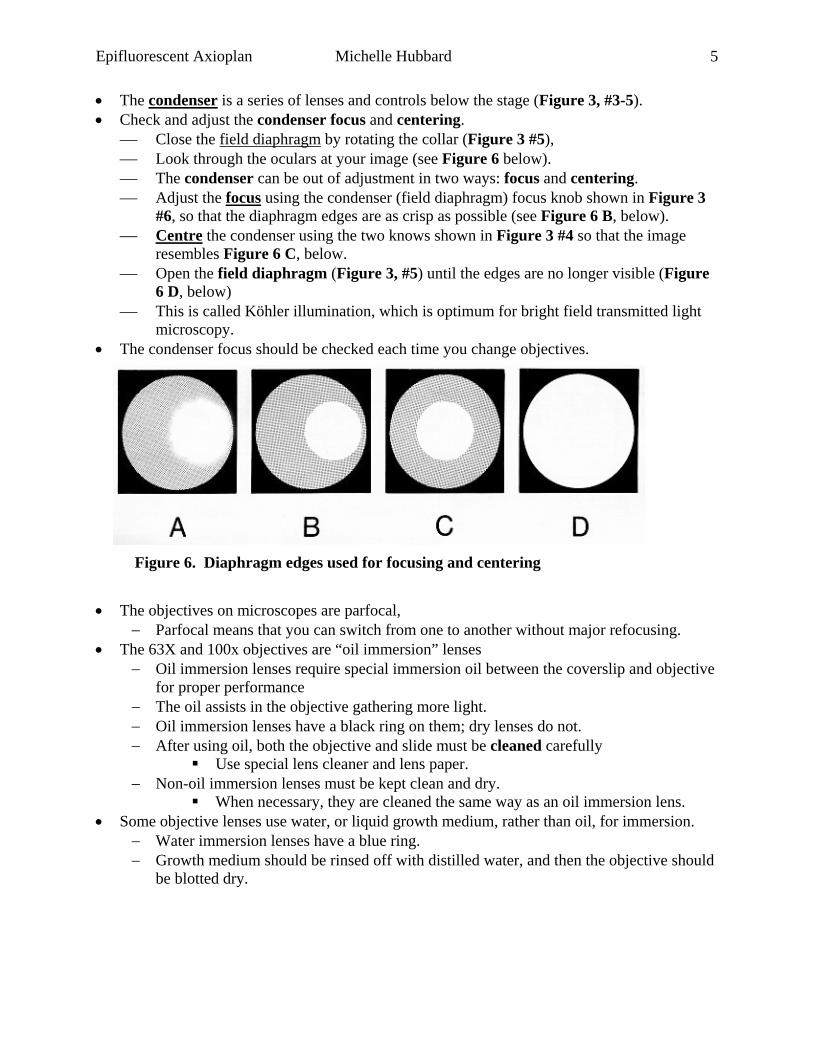
• The condenser is a series of lenses and controls below the stage (Figure 3, #3-5). • Check and adjust the condenser focus and centering.
⎯ Close the field diaphragm by rotating the collar (Figure 3 #5), ⎯ Look through the oculars at your image (see Figure 6 below). ⎯ The condenser can be out of adjustment in two ways: focus and centering. ⎯ Adjust the focus using the condenser (field diaphragm) focus knob shown in Figure 3
#6, so that the diaphragm edges are as crisp as possible (see Figure 6 B, below). ⎯ Centre the condenser using the two knows shown in Figure 3 #4 so that the image
resembles Figure 6 C, below. ⎯ Open the field diaphragm (Figure 3, #5) until the edges are no longer visible (Figure
6 D, below) ⎯ This is called Köhler illumination, which is optimum for bright field transmitted light
microscopy. • The condenser focus should be checked each time you change objectives.
• The objectives on microscopes are parfocal,
− Parfocal means that you can switch from one to another without major refocusing. • The 63X and 100x objectives are “oil immersion” lenses
− Oil immersion lenses require special immersion oil between the coverslip and objective for proper performance
− The oil assists in the objective gathering more light. − Oil immersion lenses have a black ring on them; dry lenses do not. − After using oil, both the objective and slide must be cleaned carefully
Use special lens cleaner and lens paper. − Non-oil immersion lenses must be kept clean and dry.
When necessary, they are cleaned the same way as an oil immersion lens. • Some objective lenses use water, or liquid growth medium, rather than oil, for immersion.
− Water immersion lenses have a blue ring. − Growth medium should be rinsed off with distilled water, and then the objective should
be blotted dry.
Figure 6. Diaphragm edges used for focusing and centering

Epifluorescent Axioplan Michelle Hubbard
6
Differential interference contrast (DIC) microscopy DIC microscopy uses polarized light to increase the contrast of images of unstained cells. This was developed by Nomarski, and is also called Nomarski contrast. Briefly, the specimen is illuminated with plane polarized light, and after passing through the specimen and the objective, the light passes through a second polarizing filter that is at an angle to the first. The polarity of the light is changed as it passes through the specimen, leading to increased contrast and the appearance of a three-dimensional image. There are four parts to the optical system: • The condenser lens must be appropriate to the objective – matched for numerical aperture
N.A. • The polarizer filter must be swung into the light path – this is below the condenser, but above
the field diaphragm • The analyzer filter (see “slider for DIC”, Figure 1; just above the filter sets for
epifluorescence) must be pushed into the light path • Sometimes, an additional small polarizing filter just above the objective must be adjusted for
maximum contrast, although this may be incorporated into the analyzer filter. Either way, as this ‘Wollaston” filter is rotated the image becomes more or less contrasted.
Epifluorescent Axioplan Michelle Hubbard
7
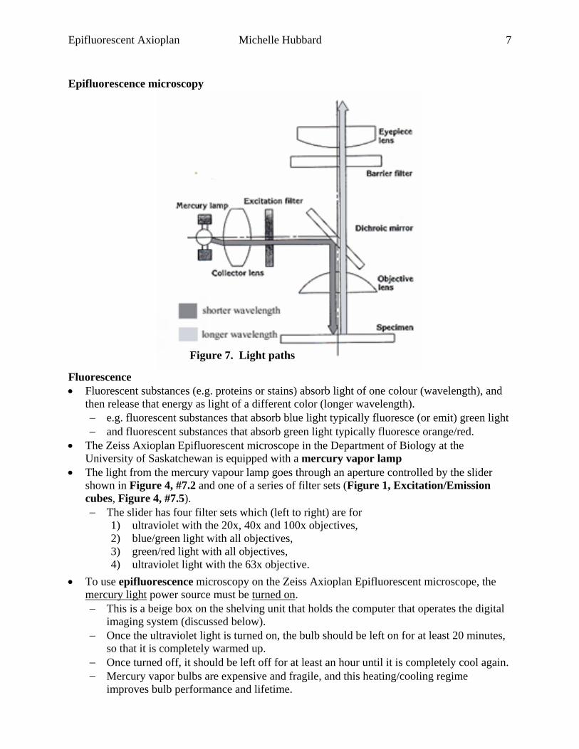
Epifluorescence microscopy
Fluorescence • Fluorescent substances (e.g. proteins or stains) absorb light of one colour (wavelength), and
then release that energy as light of a different color (longer wavelength). − e.g. fluorescent substances that absorb blue light typically fluoresce (or emit) green light − and fluorescent substances that absorb green light typically fluoresce orange/red.
• The Zeiss Axioplan Epifluorescent microscope in the Department of Biology at the University of Saskatchewan is equipped with a mercury vapor lamp
• The light from the mercury vapour lamp goes through an aperture controlled by the slider shown in Figure 4, #7.2 and one of a series of filter sets (Figure 1, Excitation/Emission cubes, Figure 4, #7.5). − The slider has four filter sets which (left to right) are for
1) ultraviolet with the 20x, 40x and 100x objectives, 2) blue/green light with all objectives, 3) green/red light with all objectives, 4) ultraviolet light with the 63x objective.
• To use epifluorescence microscopy on the Zeiss Axioplan Epifluorescent microscope, the mercury light power source must be turned on. − This is a beige box on the shelving unit that holds the computer that operates the digital
imaging system (discussed below). − Once the ultraviolet light is turned on, the bulb should be left on for at least 20 minutes,
so that it is completely warmed up. − Once turned off, it should be left off for at least an hour until it is completely cool again. − Mercury vapor bulbs are expensive and fragile, and this heating/cooling regime
improves bulb performance and lifetime.
Figure 7. Light paths

Epifluorescent Axioplan Michelle Hubbard
8
• Find your specimen using transmitted light, and then cover the transmitted light at the field diaphragm (Figure 3, #5), or turn the bulb off.
• Pull out the DIC slider − this absorbs a lot of light.
• Choose the correct filter set (Figure 1 Excitation/Emission cubes, Figure 4, #7.5) for your fluorescent stain or protein.
• Pull back the slider covering to admit ultraviolet light (Figure 4, #7.3). Note: Generally, it is easier to use epifluorescence in a darkened room.

Epifluorescent Axioplan Michelle Hubbard
9
Taking pictures with the digital camera • Turn on the computer • Choose the AxioVision icon, near the middle left-hand of the main screen. • Once you have your area of interest visible through the oculars
• Your specimen must be in the middle of the field of view, since the camera pixel array covers only about the area of the rectangle.
• Pull out the slider on the right hand side of the oculars • Press the Live button (circled and labeled 1 in Figure 10 below) on the top of the
AxioVision screen.
• At the top of the Adjust tab, under AxioCamICc1:Exposure, adjust exposure time (in ms)
and percentage, and then press the Measure button to asses the image exposure. • Longer exposures and higher percentages result in brighter images. • Ideally, the peaks in the Histogram (Figure 8) should be
Figure 8. AxioVision Histogram
Figure 9. AxioVision Transmitted light “Live” image
Epifluorescent Axioplan Michelle Hubbard
10
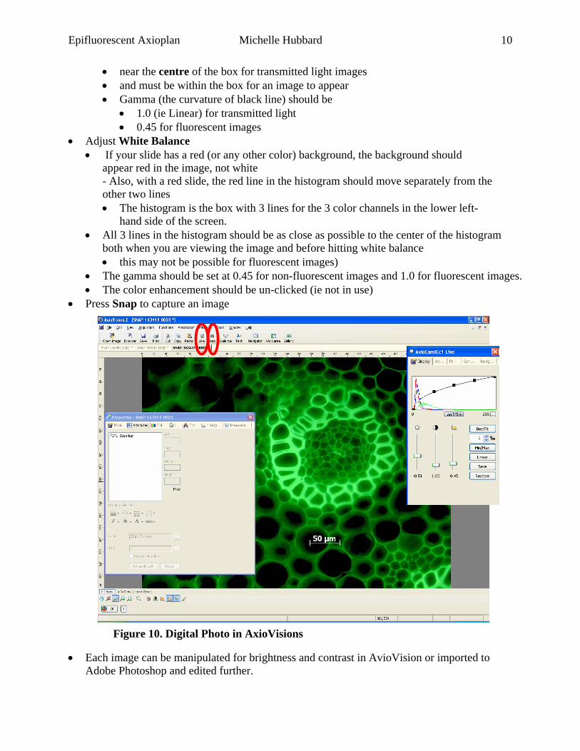
• near the centre of the box for transmitted light images • and must be within the box for an image to appear • Gamma (the curvature of black line) should be
• 1.0 (ie Linear) for transmitted light • 0.45 for fluorescent images
• Adjust White Balance • If your slide has a red (or any other color) background, the background should
appear red in the image, not white - Also, with a red slide, the red line in the histogram should move separately from the other two lines • The histogram is the box with 3 lines for the 3 color channels in the lower left-
hand side of the screen. • All 3 lines in the histogram should be as close as possible to the center of the histogram
both when you are viewing the image and before hitting white balance • this may not be possible for fluorescent images)
• The gamma should be set at 0.45 for non-fluorescent images and 1.0 for fluorescent images. • The color enhancement should be un-clicked (ie not in use)
• Press Snap to capture an image • Each image can be manipulated for brightness and contrast in AvioVision or imported to
Adobe Photoshop and edited further.
Figure 10. Digital Photo in AxioVisions

Epifluorescent Axioplan Michelle Hubbard
11
Shading Correction • Under the "General" tab of the camera control dialog,
o try un-checking the "enable" box next to the shading correction option (see Figure 11)
o see if the hyphae (contamination) disappears. • Someone carried out a shading correction while observing a specimen of the hyphae. The
software then assumes that this is contamination in the optics and tries to remove it from the image. This results in the "ghost" effect of the hyphae that you saw in your samples. To correct this please carry out a shading correction with no sample under the microscope as described in the manual or the help file.
Figure 11. Shading Correction in AxioVisions
Figure 11a. Figure 11b.

Epifluorescent Axioplan Michelle Hubbard
12
Changing the Mercury Bulb
• Release the structure which holds the mercury bulb (also referred to as mercury burner) at the bottom of box labeled above as epifluorescence light
• Remove the old mercury bulb • Put new bulb in place • Raise the new bulb in the holding structure back into the microscope
Ushio 50 Watt Mercury bulb 100 hour typical bulb life for Nikon, Zeiss, Olympus, Leica 50 Watt Epi-Fl Microscopes