eplant-sth - user manual - v2021
TRANSCRIPT

EPLANT 2021
EPLANT-STH
STRUCTURES CABLE TRAYS
HVAC
USER MANUAL
Version 2021.0 – September 08th, 2021
RELSOFT S.A. _________________________________________ Corrientes 1455 piso 3 of. 13 C1042AAA Buenos Aires – ARGENTINA Telefax (5411) 4786 3923 – www.e-eplant.com
EPLANT-STH is neither an Autodesk® nor a ZWSOFT product and it is neither guaranteed by Autodesk® nor by ZWSOFT

EPLANT-STH STRUCTURES - CABLE TRAYS - HVAC
USER MANUAL
____________________________________________________________________________________
2
INDEX
1. INTRODUCTION............................................................................................................................. 4 1.1 SYSTEM DESCRIPTION ............................................................................................................ 4 1.2 CONVENTIONS........................................................................................................................... 4 2. INSTALLATION .............................................................................................................................. 5 2.1 HARDWARE REQUIREMENTS ................................................................................................ 5 2.2 SOFTWARE REQUIREMENTS.................................................................................................. 5 2.3 INSTALLATION FROM CD ....................................................................................................... 6 2.4 INSTALLATION FROM INTERNET ......................................................................................... 6 2.5 LICENSE SETUP ......................................................................................................................... 6 2.6 NETWORK INSTALLATION ..................................................................................................... 7 2.7 INSTALLATION ERRORS.......................................................................................................... 7 2.7.1 HARD-LOCK MISSING.......................................................................................................... 7 2.7.3 INVALID EPLANT COMMANDS ......................................................................................... 7 2.8 COMPATIBILITY WITH EPLANT-Piping................................................................................. 7 2.9 DIFFERENT LANGUAGES ........................................................................................................ 8 2.10 STARTING TO WORK ........................................................................................................... 8 3. GRAPHIC MODULE....................................................................................................................... 9 3.1 INTRODUCTION......................................................................................................................... 9 3.2 MENU COMMANDS................................................................................................................... 10 3.3 ACTIVE APPLICATION ............................................................................................................. 11 3.4 ACTIVE PARAMETERS ............................................................................................................. 11 3.5 GENERAL PARAMETERS ......................................................................................................... 13 3.6 WORKING SEQUENCE.............................................................................................................. 14 3.7 GRAPHIC COMMANDS ............................................................................................................. 15 3.7.1 Component Generation ............................................................................................................. 15 3.7.2 Axis Lines Generation .............................................................................................................. 19 3.7.3 Components Modification ........................................................................................................ 21 3.7.4 Views Extractions ..................................................................................................................... 24 3.7.5 Annotations............................................................................................................................... 25 3.7.6 Interference Checking............................................................................................................... 26 3.7.7 Other Commands ...................................................................................................................... 28

EPLANT-STH STRUCTURES - CABLE TRAYS - HVAC
USER MANUAL
____________________________________________________________________________________
3
4. DATABASE MODULE .................................................................................................................... 30 4.1 INTRODUCTION......................................................................................................................... 30 4.2 OPEN THE DATABASE MODULE............................................................................................ 30 4.3 FILE 31 4.4 PROJECT SETUP......................................................................................................................... 32 4.5 3D MODELS................................................................................................................................. 36 4.6 STRUCTURES - CABLE TRAYS - HVAC................................................................................. 39 4.6.1 Original Data ............................................................................................................................ 39 4.6.2 Totalization Data....................................................................................................................... 40 4.7 REFERENCES.............................................................................................................................. 43 4.8 UTILITIES .................................................................................................................................... 45
APPENDICES Appendix A : Reference Information Appendix B : MTO Information Appendix C : SDL Parametric Language Autodesk and AutoCAD® registered trademark of Autodesk Inc. Windows and FOXPRO registered trademark of Microsoft Co. ZWCAD is registered trade mark of ZWCAD Software Co., Ltd. EPLANT is registered trademark. Copyright ? All rights reserved. Although the EPLANT system has been thorougly tested, in no event the author can be liable of any consequence generated by the use of this system. See the License Agreement for full details.

EPLANT-STH STRUCTURES - CABLE TRAYS - HVAC
USER MANUAL
____________________________________________________________________________________
4
1. INTRODUCTION This manual gives information about how to install and use the EPLANT-STH system. Other valuable source of information is the Multimedia Tutorial available in the same directory as these manuals, where a simple project is developed.
1.1 SYSTEM DESCRIPTION EPLANT-STH is a computer aided design system for the generation of tridimensional models of Structures, Cables Trays, HVAC and automatic MTO. Is built as a graphic application running on AutoCAD® with a database material management module. The system is made by a graphic application running on AutoCAD® 2004 up to 2022, ZWCAD 2018 SP2, ZWCAD 2019 SP1, ZWCAD 2020, ZWCAD 2021, ZWCAD 2022 and a database module in VisualFox. All objects generated by EPLANT-STH have parametric definition, with predefined dimensional tables, which the user can modify. Dimension tables minimize the amount of data to input and specific graphic commands make easy to build 3D models. 3D models contain all geometric and material information inside. The database module is used to integrate MTO coming from all graphic files and to manage the reference information used by the system. System architecture is designed to protect against loss of information. The same architecture assures consistency among related documents: 3D Model Material Take Off and plan extractions.
1.2 CONVENTIONS Conventions used in this manual: Indication of command selection from the AutoCAD® popup menu: [Menu 1] / [Option 1] / [Option 2] / [Command] command syntax (when indicated) This format is interpreted in the following way: [Menu 1] is the popup menu bar name, it can be [STRUCTURES] [CABLE TRAYS] [HVAC] [STH-UTI].. It is the first level of selection. [Option 1] is the selection among the menu options. It could be, for example: [Active Section] in the [STRUCTURES] menu. Some commands are executed in this way. Other may require one more. Message prompts during the graphic or data base session: the text is rendered in italics. For example: Select components
EPLANT-STH STRUCTURES - CABLE TRAYS - HVAC
USER MANUAL
____________________________________________________________________________________
5
2. INSTALLATION
2.1 HARDWARE REQUIREMENTS The same to install AutoCAD® 2004 up to 2022. ZWCAD requires less resources The EPLANT-STH graphic application uses about 3 Mbytes. Most of the EPLANT-STH requires very little additional memory. Only some commands can require 5-10 Mbytes during its execution. Memory requirement directly depends of the size of the AutoCAD® drawing files. Two different License types are supported: hard-lock based License without expiration date and Web License with Expiration date (internet connection required). The selection of the protection mode is done in the System Setup from the Data Base Module. EPLANT-STH is a system continually evolving. To verify the currently installed version: [STH-UTI] / [Generic] / [EPLANT Version]
2.2 SOFTWARE REQUIREMENTS Any of the following combinations: AutoCAD® 2004 with Windows 2000 or Windows XP. AutoCAD® 2005 with Windows 2000 or Windows XP. AutoCAD® 2006 with Windows 2000 or Windows XP. AutoCAD® 2007 on Windows XP. AutoCAD® 2008 on Windows Vista. AutoCAD® 2009 on Windows Vista. AutoCAD® 2010 on Windows Vista. AutoCAD® 2010 32 bits / 64 bits with Windows Vista 32 / 64 or Windows 7 32 / 64. AutoCAD® 2011 32 bits / 64 bits with Windows Vista 32 / 64 or Windows 7 32 / 64. AutoCAD® 2012 32 bits / 64 bits with Windows 7 32 / 64. AutoCAD® 2013 32 bits / 64 bits with Windows 7 32 / 64. AutoCAD® 2014 32 bits / 64 bits with Windows 7/8 32 / 64. AutoCAD® 2015 32 bits / 64 bits with Windows 7/8 32 / 64. AutoCAD® 2016 32 bits / 64 bits with Windows 7/8 32 / 64. AutoCAD® 2017 32 bits / 64 bits with Windows 10 32 / 64. AutoCAD® 2018 32 bits / 64 bits with Windows 10 32 / 64. AutoCAD® 2019 32 bits / 64 bits with Windows 10 32 / 64. AutoCAD® 2020 64 bits with Windows 10 64. AutoCAD® 2021 64 bits with Windows 10 64. AutoCAD® 2022 64 bits with Windows 10 64. ZWCAD 2018 SP2 on Windows 7/8/10 32 / 64. ZWCAD 2019 SP2 on Windows 7/8/10 32 / 64. ZWCAD 2020 on Windows 7/8/10 32 / 64. ZWCAD 2021 on Windows 7/8/10 32 / 64. ZWCAD 2022 on Windows 7/8/10 32 / 64.

EPLANT-STH STRUCTURES - CABLE TRAYS - HVAC
USER MANUAL
____________________________________________________________________________________
6
2.3 INSTALLATION FROM CD To start the installation: place the CD identified as EPLANT Installation in a CDRom driver. From the Explorer, select the program Setup.exe. After selecting the installation language, select from the EPLANT-STH menu bar, the Install V 2021.0 option. Follow the indications of the install program. The EPLANT-STH installer copies files to the installation directory and generates shortcuts in the \Start\Programs\EPLANT-STH menu for the Data Base module and for the documentation. It installs also the tutorial project already done in the \TEST directory nested in the main installation directory.
2.4 INSTALLATION FROM INTERNET In this case, the installation is done after downloading the sthe_2021.exe file and executing it. The installation is the same as from the CD.
2.5 LICENSE SETUP There are two different Protection modes to enabling an EPLANT-STH license. They are setup from the Data Base module: System Setup and refer to the License Type used:
In the case the License Type is set to Hardlock the hardlock itself must be connected to the computer where the system is used. Each hard-lock will enable one license to be used in the local machine. No driver installation is required. In the case the License Type is set to Web License, the License must be Activated in the computer where it will be used. Use the EPLANT Web License Manager (ep_web-x64.exe in the main installation folder) to Activate a Web License: the Serial Number file is required. See for details: Set EPLANT License Type http://www.e-eplant.com/tutorial/pde/EPLANT-Piping_Lic.html

EPLANT-STH STRUCTURES - CABLE TRAYS - HVAC
USER MANUAL
____________________________________________________________________________________
7
The Web License requires an internet connection to work and can be moved to another computer simply by repeating the registration and sending the file. Moving the license to another machine automatically disables it in the previously registered one.
2.6 NETWORK INSTALLATION If the EPLANT-STH system is to be used in a network, the easiest option is to install it in a server directory. This simplifies any system update. Every computer used to run EPLANT-STH would have the hard-lock attached to it. The installation directory must be mapped using a letter. The ep_client.exe program must be run in order to register the server installation directory on each local machine. This program can also be used in the case of any change of the main installation directory (physical or because of a different disk mapping). This program allows to locally change the License Type also, but limited to the machine running it. It is convenient to locate project directories in a server disk: different users can be working at the same time on the same project. In any case, project directories can also be located in a local disk.
2.7 INSTALLATION ERRORS
2.7.1 HARD-LOCK MISSING If executing the data base or the graphic module the following message appears: **ERROR: hard-lock missing The hard-lock is not connected to the computer where the system is being used. Web License The License has not been Activated yet: use the EPLANT Web License Manager to check its status. The License has Expired: a new Web License is needed.
2.7.2 INVALID EPLANT COMMANDS If selecting a command from the EPLANT-STH menu, the command is not recognized by AutoCAD®, it means that the graphic application is not currently loaded in the AutoCAD® environment. To achieve this, the dwg drawing file must be opened from the Windows Explorer, after closing any previous AutoCAD® session if any.
2.8 COMPATIBILITY WITH EPLANT-Piping The EPLANT-STH is totally compatible with the EPLANT-Piping module, but 3D models must be placed in separate projects: one for EPLANT-Piping and another one for EPLANT-STH.

EPLANT-STH STRUCTURES - CABLE TRAYS - HVAC
USER MANUAL
____________________________________________________________________________________
8
2.9 DIFFERENT LANGUAGES The EPLANT-STH system is installed to use the English language. But it can be configured to use other languages as well to interact with the user and for report generations. The following language code is used: E English S Spanish I Italian (*) P Portuguese (*) F French (*) D German (*) A Other (*) The language code is used as a suffix in the field names that contain descriptions. The languages with (*) are not supported yet. The language used in the graphic application is defined in the System Setup within the data base module. The language used in the report listings is defined in the Project Setup within the data base module. The menu files are stored in the corresponding format directories. For example: \FR_E\STH2000.MNU is the English version.
2.10 STARTING TO WORK EPLANT-STH works in files organized in "Projects". A project is a functional unit that allows to associate the same specifications to a set of 3D models and to generate material requisitions, automatically integrating the materials of all separated models. Physically, a project is a directory on any level, with the following structure: [disk]:\...\[project]\ The *.DWG files in the project directory are considered 3D models. [disk]:\...\[project]\DBF_S In this directory the project database files are stored. [disk]:\...\[project]\LINK This directory is used to store external documents in any format that can be linked to objects inside 3D models in case the project setup specifies the link by name. To begin a new project, a new directory must be created, using a name not more that five characters long. The directory can be placed at any level. After that the Database Module must be used at least once, to open this directory and create the project. See chapter 4 for details.

EPLANT-STH STRUCTURES - CABLE TRAYS - HVAC
USER MANUAL
____________________________________________________________________________________
9
3. GRAPHIC MODULE
3.1 INTRODUCTION Each drawing file placed in the project directory can be used to build tridimensional models and plan extractions. To create a new drawing file the void \STH\STH.DWG drawing file can be copied to the project directory. EPLANT-STH uses the metrical system unit, because dimensional tables are in mm. The EPLANT-STH graphic module is a program written in C and C++. In this way new commands are defined to AutoCAD®. The graphic module is automatically loaded and initialized by the ACAD.LSP file in the project directories. The Database module copies this file to the project directory when the project is opened. For the user convenience, the project can be divided in an arbitrary number of drawing files, all placed in the project directory. In this way all 3D models share the same reference information and the database module can automatically integrate material coming from all different models. 3D models store the complete object definitions: all dimensions and other relevant information. From 3D models other documents are automatically generated: orthographic views and MTO. All objects are built as blocks. LINE elements can be used as a guide in the model construction. View extraction generates different kind of elements, depending on the way each object is defined.

EPLANT-STH STRUCTURES - CABLE TRAYS - HVAC
USER MANUAL
____________________________________________________________________________________
10
3.2 MENU COMMANDS EPLANT-STH adds four new menu bars to the original AutoCAD® ACAD.MNU menu. The menu file STH2004.MNU can be modified. From these four bars all commands can be selected. The menu structure is detailed below. The firsts three options are specific to each application. The last one STH_UTI contains common commands to all applications.

EPLANT-STH STRUCTURES - CABLE TRAYS - HVAC
USER MANUAL
____________________________________________________________________________________
11
3.3 ACTIVE APPLICATION Objects generated by EPLANT-STH are grouped in different classes, called Applications. There are three defined Applications: Structures, Cable Trays and HVAC. In a working session there is only one active application. Commands used to generate different objects are set in different menus, separated by application (see 3.2). To be able to use them, the corresponding application must be active. The first command in the STH_UTI bar is used to this aim, which opens the following window:
3.4 ACTIVE PARAMETERS Each Application stores both in memory and in the drawing file, the parameters used by default within each application. This schema is the same for each application. Let see it for the Structure Application, selecting the first option Active Section from the Structure menu bar.

EPLANT-STH STRUCTURES - CABLE TRAYS - HVAC
USER MANUAL
____________________________________________________________________________________
12
Let see the meaning of each parameter. Between parenthesis the equivalence for the other applications are indicated. Structure Name Each 3D object is associated to a Structure (Cable Tray / Duct). Its name is the Active Name that can be selected from the popup menu. To generate a new name, type it in the edit box at the right and confirm with an Enter. The layer with name S3_[structure_name] (T3_[Cable_tray_name] / H3_[Duct_name]) will be generated. 3D Components Color It is the color number assigned to the layer corresponding to the Active Structure. Section Type It is the type of the Active Section. On modifying it, the associated slide and the Active Section popup content will be modified. In the case of Structure it is only used as default selection when displaying section menus. For Cable Trays and HVAC represent the Tray / Duct section type and is used as a filter when selecting any placement menu. Section It is the Active Section. It shows the content of the corresponding file section associated with the Active Section Type. It is used as default section in any placement menu. Material It is Active Material. It shows the content of the materials defined in the \STH\STD\MAT.DBF file. Standard It is the Active Dimension Standard. It shows all standards defined for the Structure Applications: they are all the directories contained in the \STH\STD\S directory (\STH\STD\T \STH\STD\H). Graphic Selection It allows to set the Active Section to the section of a graphically selected component.

EPLANT-STH STRUCTURES - CABLE TRAYS - HVAC
USER MANUAL
____________________________________________________________________________________
13
3.5 GENERAL PARAMETERS They are other parameters that set default values. They are modified with the option General Settings in the STH_UTI menu bar. The following window will open. Look to the help button for detailed information about each parameter:

EPLANT-STH STRUCTURES - CABLE TRAYS - HVAC
USER MANUAL
____________________________________________________________________________________
14
3.6 WORKING SEQUENCE Basically the working sequence can be the following: - Project directory generation
In this directory the project 3D models must be placed. At least once this directory must be open with the Database module to generate the nested \DBF_S directory and all the required files.
- 3D Model
A new void drawing file is created in the project directory. An arbitrary number of such files can be used.
- Active Application setting
Depending of what components are being generated, the corresponding Application must be set Active.
- Active Parameters setting
The active parameters of the current application must be set. In case of Structure: the Structure Name, the Section Type, the default section, the material and the standard. In case of Cable Trays: the Cable Tray Name, the Section Type, the default section, the material and the standard. In case of HVAC: the Duct Name, the Section Type, the default section, the material and the standard.
- Reference lines generation
Reference lines are generated with the LINE command, to be used as drawing references in the 3D files. To predefined typology the Axis Generation command can be used.
- Component Generation
The required components are generated, connecting them to existing ones or using reference lines. - Seccion Association to axis
In case of Structure a section is assigned to a drawn axis. - Component Generation from Axis
In case of Structure, if any section has been assigned to axis, the corresponding 3D component will be automatically generated.
- Plan Generations
Plan views are extracted, along the required orientation, with the View Extraction command. They are completed with dimensions and notes.
- 3D Models Material Take Off
The Report to DB command allows to update the Database module materials. - Material Requisitions
From the Database module a New Total can be executed, to generate a new revision of Material Requisitions.

EPLANT-STH STRUCTURES - CABLE TRAYS - HVAC
USER MANUAL
____________________________________________________________________________________
15
3.7 GRAPHIC COMMANDS
3.7.1 Component Generation All components are parametrically defined. The user can modify their definitions as well as to define new ones (see Appendix C). They are classified in four different types: - Linear: they have a constant section, with its length defined by the user. For example a structural
section, a straight cable tray, a rectilinear duct segment. They have associated a dimensional table with the parameter dimensions by sections. Their length can be changed at any moment with the Cut Component command.
- Volumetric: all parameters are manually input during their creation. It is the case of prisms, plates,
etc. - With one section: their dimensions depend by a section. They are associated to a dimension table
where the parameters are by section. It is the case of Elbows. - With two sections: their dimensions depend by two sections. They are associated to a dimension
table where the parameters are by section. It is the case of Reductions. All components are generated with the following sequence: - The option that identifies the component category is selected from the corresponding menu. For
example, for Structures: Sections. The following window will appear:

EPLANT-STH STRUCTURES - CABLE TRAYS - HVAC
USER MANUAL
____________________________________________________________________________________
16
The first popup menu allows to select the Section Type. This menu will show the Active Section as the default value. In case of Structure, all linear components can be selected from this menu, but for the other applications, to change the Section Type here, the Active Section must be changed before. With those application it is assumed that during the generation of a tracing, the section type won't be changed. The component type and dimensions can be imported selecting an existing component, with the Graphic Selection button. Only components belonging to the Active Application and to the same class can be selected this way. If the Standard, the Material or the Structure / Cable Tray / Duct name are different with respect to the active ones, the command offers the option to honor the active ones or to change them. In this case the Dimensions button is disabled, because it is a component that automatically reads its dimension from tables. The Section 1 shows the selected section. When this dialog box opens, it is the active section, but it can be modified. Before to be able to generate the component, the position and orientation are to be defined. To this aim two different POSITION buttons are available The POSITION button prompts to select a point. This point corresponds to the red cross in the dialog box slide. Three cases are possible: - A point over an object generated with EPLANT-STH is selected. A cross will snap to the nearest connection point. The command automatically reads the coordinates of that point and of the other two associated points that are used to define the orientation of the component face. - A point over LINE segment is selected. In the command line will appear, as an example:
EPLANT-STH STRUCTURES - CABLE TRAYS - HVAC
USER MANUAL
____________________________________________________________________________________
17
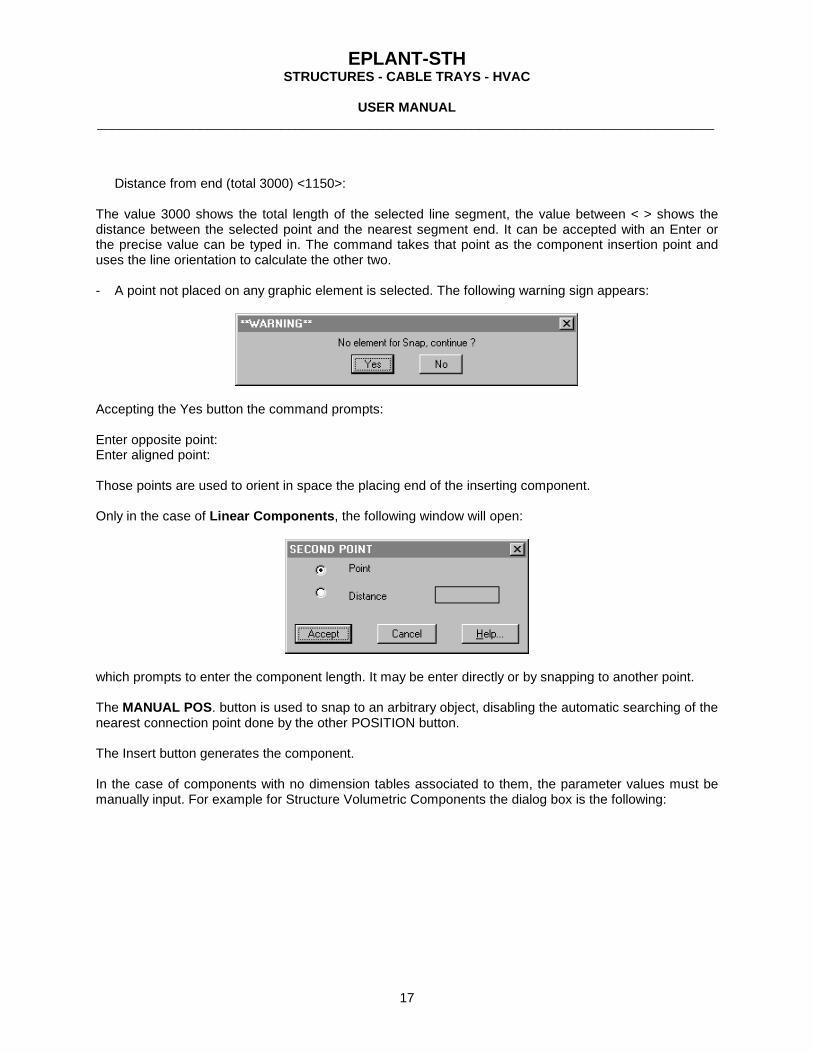
Distance from end (total 3000) <1150>: The value 3000 shows the total length of the selected line segment, the value between < > shows the distance between the selected point and the nearest segment end. It can be accepted with an Enter or the precise value can be typed in. The command takes that point as the component insertion point and uses the line orientation to calculate the other two. - A point not placed on any graphic element is selected. The following warning sign appears:
Accepting the Yes button the command prompts: Enter opposite point: Enter aligned point: Those points are used to orient in space the placing end of the inserting component. Only in the case of Linear Components, the following window will open:
which prompts to enter the component length. It may be enter directly or by snapping to another point. The MANUAL POS. button is used to snap to an arbitrary object, disabling the automatic searching of the nearest connection point done by the other POSITION button. The Insert button generates the component. In the case of components with no dimension tables associated to them, the parameter values must be manually input. For example for Structure Volumetric Components the dialog box is the following:

EPLANT-STH STRUCTURES - CABLE TRAYS - HVAC
USER MANUAL
____________________________________________________________________________________
18
In this case, the GRAPHIC SELECTION is very handy because it allows to import manually loaded dimensions of existing objects, to generate another similar one modifying its dimensions. Selecting the DIMENSIONS button the following dialog box will open, that must be loaded in all required fields:

EPLANT-STH STRUCTURES - CABLE TRAYS - HVAC
USER MANUAL
____________________________________________________________________________________
19
3.7.2 Axis Lines Generation Inside the Structures Application, parametrically defined Axis Lines can be generated. A section is assigned to each axis and the 3D corresponding section can be generated. This is the common way to generate sections. The command: [STRUCTURES] [Axis Generation] opens the following window:
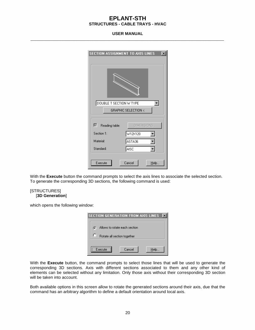
From the menu the required typology is selected; the parameter values are specified and the origin of the current typology is set. Each typology is parametrically defined, using the same languange used to defining components. See apendix C. Once the axis have been generated, the following command is selected: [STRUCTURES] [Section Association] which opens the following window, similar to the one used in component generation:
EPLANT-STH STRUCTURES - CABLE TRAYS - HVAC
USER MANUAL
____________________________________________________________________________________
20
With the Execute button the command prompts to select the axis lines to associate the selected section. To generate the corresponding 3D sections, the following command is used: [STRUCTURES] [3D Generation] which opens the following window:
With the Execute button, the command prompts to select those lines that will be used to generate the corresponding 3D sections. Axis with different sections associated to them and any other kind of elements can be selected without any limitation. Only those axis without their corresponding 3D section will be taken into account. Both available options in this screen allow to rotate the generated sections around their axis, due that the command has an arbitrary algorithm to define a default orientation around local axis.

EPLANT-STH STRUCTURES - CABLE TRAYS - HVAC
USER MANUAL
____________________________________________________________________________________
21
3.7.3 Components Modification Commands that modify some characteristic of placed components are found in the STH-UTI menu. Move Component Orientation It prompts to select the graphic elements to move: Select connection point to move: Select final connection point: It moves all selected elements in a way to always assure the proper connection between the two component faces at the selected points. Move Component Point It prompts to select the graphic elements to move: Select connection point to move: Select final connection point: It moves all selected elements doing only displacements along the coordinate axis to assure the connection between the selected points, but not forcing the connecting faces to aligned in any way. Cut Component It prompts to select the first elements to modify (it is used in case of taking references against other components) and other component to modify if any. Only components having linear type will be modified, all other components will be ignored, as well as elements directly drawn with AutoCAD®. The following dialog box will appear:
The cut length at each end is specified. A positive value refers to an increase of length, whereas one negative to a decrease. Values can be input by typing them or by graphical selection. References with other components allow to preciselly cut the selected component with respect other connecting components. Rotate Component It prompts to select the graphic elements to rotate. Only components having linear type will be modified, all other components will be ignored, as well as elements directly drawn with AutoCAD®. The following dialog box will appear:

EPLANT-STH STRUCTURES - CABLE TRAYS - HVAC
USER MANUAL
____________________________________________________________________________________
22
For each component, the Rotation is executed around the checked local axis. To display the local axis of a component use the Show Local Axis button. In the same way, the rotation angle can be manually input, loaded with fixed value buttons or graphically selected with the Graphic Selection button. Modify Component Allows to modify all characteristics of existing components. Prompts to select the first elements to modify (takes form it the component type) and other component to modify if any. Only components having the same type as the first selected one will be modified, all other components will be ignored. The following dialog box opens:

EPLANT-STH STRUCTURES - CABLE TRAYS - HVAC
USER MANUAL
____________________________________________________________________________________
23
This command can also assign an additional text parameter named Tag. Depending on project setup, external documents can be associated to this Tag. It can be used, for example, as a Unique Part Number and the external documents can be related to inspection and maintenance work.

EPLANT-STH STRUCTURES - CABLE TRAYS - HVAC
USER MANUAL
____________________________________________________________________________________
24
3.7.4 Views Extractions Structure models generated with EPLANT-STH are tridimensional models and as such, they can be viewed from any direction to obtain orthogonal projections to be used in plans drawings. Nevertheless, each component being a block that cannot be exploded, also a slight modification that may be required on them would be impossible. For this reason the View Extraction command is used. This command is selected from the STH-UTI menu. It generates a plan view of the model along the orientation of the current UCS XY plane. The graphic elements that are generated have all the characteristics of the original 3D components. In this way the Annotation commands can be used (see 3.7.4). Selecting the View Extraction command, the following dialog box opens:
Choosing the All File option, the extraction will be extended to all components present in the current drawing file, including also those with OFF or FREEZE layers. Checking the Z Filter option enables the Zmin Zmax button that allows to assign a range to the Z coordinate of the current UCS at the moment of extraction: only those components whose insertion points are inside that range will be extracted. Component selection can be also limited by application and the corresponding extracted elements can be sent to different layers. The options Opaque and Transparent allow to generate elements that are either opaque to the AutoCAD® command Hide or transparent to it. In this later case the user can modify the elements. In the following figures two different projections of the same section are shown.

EPLANT-STH STRUCTURES - CABLE TRAYS - HVAC
USER MANUAL
____________________________________________________________________________________
25
Projection in a plane perpendicular to the section axis.
Projection in a plane parallel to the section axis. EPLANT-Piping can automatically generate 2D views of EPLANT-STH 3D models. Just attach the EPLANT-STH files in a dwg placed in the PLE EPLANT-Piping folder.
3.7.5 Annotations It is possible to automatically place notes with information extracted from the selected component. Use the commands grouped in the Annotations option, in the STH_UTI menu:

EPLANT-STH STRUCTURES - CABLE TRAYS - HVAC
USER MANUAL
____________________________________________________________________________________
26
Notes are generated as TEXT elements, using the active Style in the moment of their placement. The WCS Coordinates of the selected end are expressed in the WCS system. The GEO Coordinates take the North direction along the WCS X axis. If a NORTH block is inserted somewhere in the drawing, takes its insertion angle as the true north direction (only multiple of 90 degrees are accepted). All but the coordinate options, the information generated by the annotation commands can have two different formats: a text or a block with an attribute. The syntax of the command specifies the required option. Two example are given below: (set_par "PAR" "ID:ID:") sth_anno generate the identification of the selected component, placing a text with its identification parameter, with the prefix ID:. In this case the text could be ID:W36x210. The text used as prefix can be up 50 characters long. (set_par "PAR" "ID&ID") sth_anno inserts a block with a name specified with the characters following the & symbol (in this case ID). This block must be placed in the parametric definition directory (\STH\SDL) and must have the attribute ANNO. In both cases, the text or the block is joined to the selected object by a line. The note is generated in the current UCS XY plane and in the active layer.
3.7.6 Interference Checking Interference checking between components of the three application can be performed visually or using a specific command, selecting the menu option STH_UTI / Interference. The following dialog box opens:
Interference checking can be used in two different ways: checking the Control Component option, a single component will be checked for interference against all others in a group; checking the Set option, all components selected will be checked against each others for interferences. In the first case, upon exiting this dialog box with the Execute button, the command will prompt to select the control component and then the rest of elements to be checked. In the second case, only the selection of a set will be performed.

EPLANT-STH STRUCTURES - CABLE TRAYS - HVAC
USER MANUAL
____________________________________________________________________________________
27
In both cases the total number of components to be checked must be less than 5000. If a greater number is needed, the checking must be limited to a part of the drawing and the same operation will have to be repeated again. In the interference checking, each component is approximated by a right prism, defined along with the 3D representation, in the parametric definition file. The Tolerance parameter refers to the possibility to increase the dimensions of each component to be able to verify a volume of space outside it. Each component has defined (in the \STH\STD\CMP.DBF) which dimension can be increased and which not. It avoids in this way to increase the length of a rectilinear Cable Tray. If the Graphic Indication option is checked, each time an interference is detected, the command makes a Zoom Window centered in the interference point, shows both interfering components highlighted, draws a cross on the interference point and opens he following dialog box:
Selecting the Continue button, the command looks for the next interference, if any. Selecting the Zoom Window button, the command makes a Zoom Window centered on the interference point with the window size indicated. Selecting Zoom Extend will do this very AutoCAD® command.
EPLANT-STH STRUCTURES - CABLE TRAYS - HVAC
USER MANUAL
____________________________________________________________________________________
28
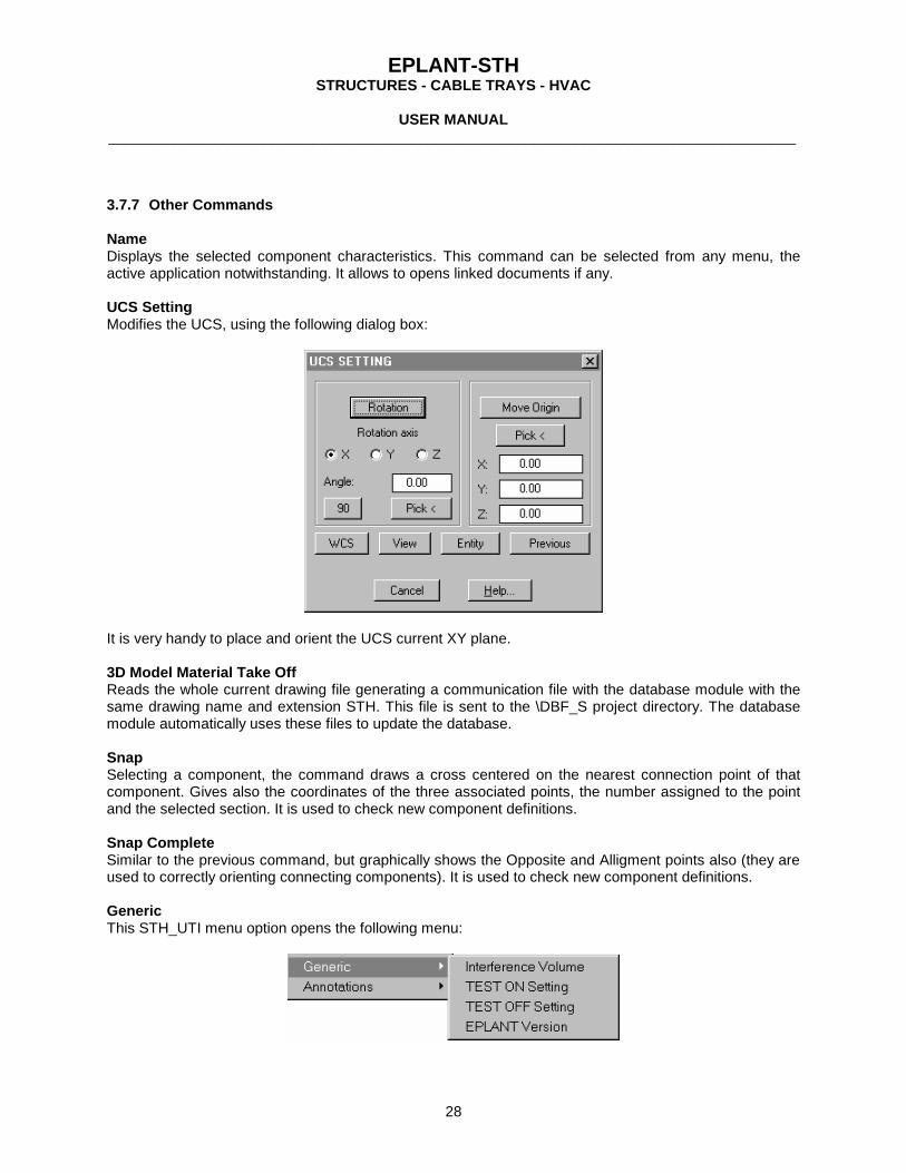
3.7.7 Other Commands Name Displays the selected component characteristics. This command can be selected from any menu, the active application notwithstanding. It allows to opens linked documents if any. UCS Setting Modifies the UCS, using the following dialog box:
It is very handy to place and orient the UCS current XY plane. 3D Model Material Take Off Reads the whole current drawing file generating a communication file with the database module with the same drawing name and extension STH. This file is sent to the \DBF_S project directory. The database module automatically uses these files to update the database. Snap Selecting a component, the command draws a cross centered on the nearest connection point of that component. Gives also the coordinates of the three associated points, the number assigned to the point and the selected section. It is used to check new component definitions. Snap Complete Similar to the previous command, but graphically shows the Opposite and Alligment points also (they are used to correctly orienting connecting components). It is used to check new component definitions. Generic This STH_UTI menu option opens the following menu:
EPLANT-STH STRUCTURES - CABLE TRAYS - HVAC
USER MANUAL
____________________________________________________________________________________
29
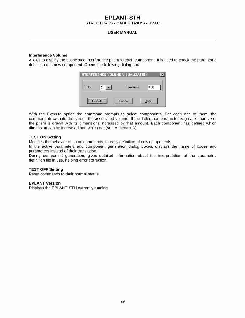
Interference Volume Allows to display the associated interference prism to each component. It is used to check the parametric definition of a new component. Opens the following dialog box:
With the Execute option the command prompts to select components. For each one of them, the command draws into the screen the associated volume. If the Tolerance parameter is greater than zero, the prism is drawn with its dimensions increased by that amount. Each component has defined which dimension can be increased and which not (see Appendix A). TEST ON Setting Modifies the behavior of some commands, to easy definition of new components. In the active parameters and component generation dialog boxes, displays the name of codes and parameters instead of their translation. During component generation, gives detailed information about the interpretation of the parametric definition file in use, helping error correction. TEST OFF Setting Reset commands to their normal status. EPLANT Version Displays the EPLANT-STH currently running.

EPLANT-STH STRUCTURES - CABLE TRAYS - HVAC
USER MANUAL
____________________________________________________________________________________
30
4. DATABASE MODULE
4.1 INTRODUCTION The EPLANT-STH system database module has two main objectives: to have access to system reference tables (mainly dimension tables, see Appendices A and B) and automatically integrate the material contained in each graphic models included in the project. All kind of reports can be generated, including Material Requirements with revision tracking.
4.2 OPEN THE DATABASE MODULE Select the EPLANT-STH Data Base option menu:
Executing the Data Base module, the following menu will appear:
Only options not refering to a specific project are enabled. Let see every option of the main menu. After the system installation, and also after a version upgrade, the Protection Type selection must be verified. To open the System Setup select:
and from the main menú select the License Type button:

EPLANT-STH STRUCTURES - CABLE TRAYS - HVAC
USER MANUAL
____________________________________________________________________________________
31
See chapter 2.5 for details. To enter to the System Setup the license is not required, as well as for using general options in the UTILITIES menu bar. For all other options a valid license is required.
4.3 FILE The bar File opens the following options:
Open Project Allows to select a directory (any level, with a name no more than five characters long) that will be regarded as the Project directory. The first time a project is opened with EPLANT-STH, the command will prompt if the user wants to transform it in an EPLANT-STH project. This option automatically generates some nested directories and copies reference files. It enables also most of the options in the menu bars, verifies project files existence (if they are missing they are automatically copied from system seeds) and performs the searching of the *.STH files in the \DBF_S project directory. These files are generated from the graphic module with the [Report to DB] command and contain material data corresponding to 3D models that is automatically loaded into the database module. During this updating process, any detected error is displayed into the screen and written in the \[project_code]\DB_STH.ERR file that can be opened with the last option of the Utilities bar menu. System Setup Allows to modify system settings that are used to generate default setting for new projects. It is also used to change the interface language. Project Setup Allows to modify Project settings for example the report language.

EPLANT-STH STRUCTURES - CABLE TRAYS - HVAC
USER MANUAL
____________________________________________________________________________________
32
4.4 PROJECT SETUP Selecting the Project Setup option, the following dialog box opens:
Exiting with the Accept button all modifications are stored on disk. The project setup is contained in the \[project_code]\DBD_S\[project_code]SET.DBF file. When a new project is generated, this file contains default values copied from the system setup file, that can also be modified with the corresponding option in the File menu. Each button in this dialog box allows to have access to sets of related parameters to modify them. Let's detail each option. Use the Help button to understand the meaning of each parameter. Selecting the Default Standards the following dialog box will opens:
Component Catalog: default value is System and means that the Dimensional Catalogs used by the current project are catalogs defined by the system that can be used by other projects as well. In case of Project, the catalogs and component definition files are specific for the current project only and are placed under the project CAT \ STD_S folder. If there is not a valid reason, the defauly System option must be used. In case of the Project option, the parametric definition files are located in the project CAT \ SDL folder also. Standards selected in these popups are default standards for the current project. They can be changed at any moment. Selecting the General Parameters options the following dialog box opens:

EPLANT-STH STRUCTURES - CABLE TRAYS - HVAC
USER MANUAL
____________________________________________________________________________________
33
Report Language affects descriptions in translation tables (for example the generic description associated to each component in the \STH\STD\CMP.DBF table) and report format files. Changing the language, these files are automatically copied from the system to the DBF_S project directory. In case of System Setup, this very window allows to change the interface language that is immediately modified upon exiting the Setup. Share access to tables refers to the possibility of more than one user working at the same moment. Project Name is a text that can be referenced in every report. Enable Graphic Reports: allows to disable this options for read'only projects. Verify Registered Applications checks for the presence of other registered applications in the graphic file, apart from EPLANT-STH and AutoCAD® which generally are associated with corrupted objects within the drawing file.

EPLANT-STH STRUCTURES - CABLE TRAYS - HVAC
USER MANUAL
____________________________________________________________________________________
34
Selecting the 3D Model Settings the following dialog box opens:
It allows to define the color assigned to layers used for the different applications and objects. Selecting the External Data Link button, the following window opens:
In this dialog box the criteria used to link 3D elements with external documents is set. Selecting the Requisition Options button, the following dialog box opens:

EPLANT-STH STRUCTURES - CABLE TRAYS - HVAC
USER MANUAL
____________________________________________________________________________________
35
The first selection refers to the way revisions are assigned during Material Requisition generation. In the first option, requisitions have assigned a successive number starting from zero. In each revision all requisitions are issued. In the second option, revisions are assigned depending on the sequence driven by a project table that can be modified. In each revision only checked requisitions are issued. Each one can follow a different issuing history. If the Purchase Quantity option is not checked, the purchase quantity for each item is calculated as the computed quantity increased by the surplus corresponding to that requisition. Otherwise, if checked the purchase quantity for each item is calculated as the greater between the last revision purchase quantity and the currently computed quantity incremented by the surplus quantity. The first option is generally more used. The second option is used when a first preliminary revision is issued with estimated material that are deleted just after issuing the first revision, to avoid that these materials can be duplicated with the same material coming from 3D models. With this setting, a wrong estimate is detected comparing the computed and purchase quantities. Selecting the Plan Extraction button the following dialog box opens:
Layers and colors are default values that can be changed during the View Extraction process.

EPLANT-STH STRUCTURES - CABLE TRAYS - HVAC
USER MANUAL
____________________________________________________________________________________
36
4.5 3D MODELS The first option allows to display information about project 3D drawing files and their material updating status in the database module. From this bar the following menu opens:
The Browse option opens a window of the kind shown below:
The left most field displays all files with DWG extension in the project directory (regarded 3D models), with their last modification date and time. In the Report Status field, the current material report status is shown for each 3D model. Four different cases can happen: Graphic Report OK The MTO is updated with respect the last revision of the 3D model. Update Graphic Report The Report to DB must be executed again in the drawing file because of possible changes in the 3D model. Never Computed The Report to DB must be executed in the drawing, otherwise any material coming from this model will never come into the database module. Graphic file no longer exists In this case, in some time in the past, a Graphic Report was executed from a 3D model that no longer exist now. May be the original drawing file was deleted or renamed. In any case, if the report contains material that we don't want to compute now, the corresponding STH file in the project DBF_S directory must be deleted and the project open again to delete all material associated to it. The Reports option opens the following menu, common to all other Report options:
Screen shows the report into the screen, with a simplified format.

EPLANT-STH STRUCTURES - CABLE TRAYS - HVAC
USER MANUAL
____________________________________________________________________________________
37
Selecting Printer the following prompts appears: Document N.: that allows to enter a Document Number to be referenced in the report (it is stored in the global variable NDOC) and next the following menu opens:
Print sends the report to printer. Before the printing, a dialog box will open allowing printer and pages selection. The report format can be modified with the following option. Modify Report Format opens the FoxPro Report Writer on the format definition file corresponding to the selected option. Report format files are stored in the system and project directories, depending on the information to report. Once in the Report Writer, the window is separated in three different parts, identified with their names at their left: Page Head put the report head here. Detail the space to define the report content. Page Foot put the report footing here. To input a fixed text reference, select the button. Select with the mouse where to start the text and type it. Fields with a rectangular shape outside contain variable names. To modify one, select it with a double click. To add a new one, select in the left menu the button, give two points to define its dimensions and type the field definition. To add a line, select the button. To increase or decrease the size of these three windows, use the buttons on the left border. The Preview button shows a preview of the current report. In the variable fields, any of the fields of the open tables can be referenced, along with global variables such as prj_code (the project code), prj_name (the project name defined in the setup), internal variables and algorithms defined with FOXPRO functions. The Text File option in any Listing option generates the report in a text file using an internal text file report generator. All report formats to text files are stored in the following files: \[project]\DBF\[project]RTH.DBF/FPT \[project]\DBF\[project]RTF.DBF Selecting the Text File option the following prompts appears: Document N.: that allows to enter a Document Number to be referenced in the report (it is stored in the global variable NDOC) and next the following menu opens:

EPLANT-STH STRUCTURES - CABLE TRAYS - HVAC
USER MANUAL
____________________________________________________________________________________
38
Generate Report to Text File. Prompts for: Enter file name (with extension): The output report file name must be typed. It will be placed in the project directory. Modify Header. A window will open on the header definition that is basically a text file with the header fixed parts in it. Any variable text can be place on it during the report generation, assigning the H code to it. Modify Format. A window will open displaying the current report format. Each record corresponds to a variable to be written in the report body or header. Follows a description of the meaning of each field. - Field Definition: contains the information to report. Place the field name to list. Any open table can be referenced. Accepts the FoxPro 2.6 syntax. - X Pos: is the position of writing, in characters units, from the left margin starting with 1 - Y Pos: is the position of writing, in lines units, from the upper margin starting with 1. For fields in the report body, this line is the current line: the 1 is the current one, the 2 are the following one, etc. - Width: it is the number of characters written from this field. It overwrites anything below. Fields are written in the order that appear in this window. - Memo: logic field: if T (true) the corresponding field contains a reference to a memo field, whose content is formatted using the specified width and generating as many lines needed to write the whole memo text. If left blank, only one line is used to write the field content. Only one Memo field can be defined for a report. - Code: G/H. It can have three possible values: Void: for fields to be written in the report body. There can be an arbitrary number of these fields. H: it is a header field. There can be an arbitrary number of these fields. G: it is the definition of a Group: when its value changes a new header is written. Only one Group field can be defined for a report. In this case, the table to list must be sorted with this field. Add Field. The window of the previous option will open with a void new record to fill with the new field. Preview. It generates a preview window.

EPLANT-STH STRUCTURES - CABLE TRAYS - HVAC
USER MANUAL
____________________________________________________________________________________
39
4.6 STRUCTURES - CABLE TRAYS - HVAC These three options have the same menu sequence and allow to have access to the currently open project components, separated by application. Selecting any of them, the following menu opens:
Original Data refers to data contained in the graphic files as they are generated, with the implicit elements and manual data loaded in the database module. While it is possible to delete manually loaded data, it is not possible to delete material coming from graphic files. Totalization Data refers to totalization data used to generate material requirements. During totalizations the total quantity of the same material is computed.
4.6.1 Original Data Selecting the Original Data option, the following options are available:
The Browse opens a window in the project material table [project]STH.DBF with a filter placed in the APPL field to display components belonging to the selected application only. All information can be seen, but it cannot be modified. The Browse with condition allows to filter project components based on one or more conditions imposed on their parameters: the required fields and their values can be selected from a menu. This option is very handy to pick up the spatial localization of a required component. The Add Manual Data allows to manually adding material to the project. This possibility can be used to load material estimates in the early phases of a project or to load material of a part of the project not done with EPLANT. The Brows/Mod/Delete Manual Mat. allows to display and delete material manually loaded to the project. The Reports option opens the following options:

EPLANT-STH STRUCTURES - CABLE TRAYS - HVAC
USER MANUAL
____________________________________________________________________________________
40
The One Structure option generates the report of all material belonging to the structure that is selected next from a popup menu. All materials will appear with all their characteristics. The One File option generates the report of all material belonging to the file that is selected next from a popup menu. All materials will appear with all their characteristics. The All Structures option generates the report of all material belonging to the current project. All materials will appear with all their characteristics. The Totalization: One Structure option generates the report of the material belonging to the structure that is selected next from a popup menu. Only the total quantity for each different material is included in the report. The Totalization: One File option generates the report of the material belonging to the file that is selected next from a popup menu. Only total quantity for each different material is included in the report. The Report with Conditions selects the material to report based on conditions applied as filter in the same way explained above in the Browse with conditions option. The Totalization with Conditions selects the material to report based on conditions. Only the total quantity for each different material is included in the report. The Sum with Conditions option is the same as the previous one, but the totaling key is defined by the user choosing among available fields. Output is sent to a text file in a table form with as many columns as the selected totaling keys plus the QUANTITY field that holds the total quantity for each material. The next menu selects the report output device with the same menu already explained in 4.5.
4.6.2 Totalization Data In the case the current project Material Requisition setup option specifies to use a table with the possible revisions (it is the most used configuration), from the Totalization Data option in the Structure menu, the following menu opens:

EPLANT-STH STRUCTURES - CABLE TRAYS - HVAC
USER MANUAL
____________________________________________________________________________________
41
Selecting the first option, the following menu opens:
The Material Summary allows reporting the materials with both their computed and purchasing quantity. Default value for the purchase quantity is the computed quantity plus a surplus (expressed in %) if any. It uses the \[project\DBF_S\[project]RES format file. The Material Requirements (or Requisition) is similar to the previous one, but it only shows purchase quantities comparing with the previous revision. It uses the \[project\DBF_S\[project]REQ format file. The Requisitions New Materials Only is similar to the previous one, but it only shows only those materials that have a positive difference in purchase quantities comparing with the previous revision. It uses the \[project\DBF_S\[project]REQ format file. These options allow to list all the project materials or to select only one requisition at a time. Purchase Quantity Modification allows modifying the purchase quantity for the current revision. A window will open, divided in two parts: in the left one, to each line a different item corresponds, with details in the right window. The computed quantity is displayed in the COMPUTED field (the real field name is QUANTITY). The quantity to purchase is displayed in the PURCHASE field (the real field name is REQUIRED) that is the only one that can be modified. During the Total generation, the purchase field is loaded with the computed quantity plus the surplus value, if defined for that requisition in the Requisition Titles table. Revisions to be Issued option allows selecting those requisitions to issue and their revisions. The following dialog box opens:
Requisitions that will be issued have the Issue option checked. Default revision for each requisition is the first available one, but another revision can be also selected. New Totalization executes a new material totalization. It generates a new revision only if the last one was issued, otherwise will use the last one. The following window will open:

EPLANT-STH STRUCTURES - CABLE TRAYS - HVAC
USER MANUAL
____________________________________________________________________________________
42
When this option is Accepted, the quantities of the materials having the same characteristics are summed together. Two components are considered the same if the following fields, in the [project]STH.DBF table, contain the same parameters: APPL application code CMP component code ID identification SEC1 end 1 section SEC2 end 2 section SEC3 end 3 section SEC4 end 4 section STD standard MAT material code
EPLANT-STH STRUCTURES - CABLE TRAYS - HVAC
USER MANUAL
____________________________________________________________________________________
43
4.7 REFERENCES
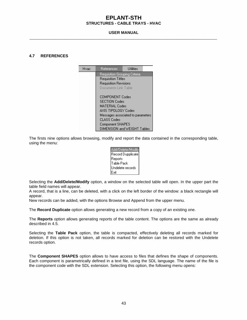
The firsts nine options allows browsing, modify and report the data contained in the corresponding table, using the menu:
Selecting the Add/Delete/Modify option, a window on the selected table will open. In the upper part the table field names will appear. A record, that is a line, can be deleted, with a click on the left border of the window: a black rectangle will appear. New records can be added, with the options Browse and Append from the upper menu. The Record Duplicate option allows generating a new record from a copy of an existing one. The Reports option allows generating reports of the table content. The options are the same as already described in 4.5. Selecting the Table Pack option, the table is compacted, effectively deleting all records marked for deletion. If this option is not taken, all records marked for deletion can be restored with the Undelete records option. The Component SHAPES option allows to have access to files that defines the shape of components. Each component is parametrically defined in a text file, using the SDL language. The name of the file is the component code with the SDL extension. Selecting this option, the following menu opens:

EPLANT-STH STRUCTURES - CABLE TRAYS - HVAC
USER MANUAL
____________________________________________________________________________________
44
The Modify Existing File option displays in a menu all SDL files found in the \STH\SDL directory. Selecting one an edit window will be open on it. Appendix C documents the SDL language syntax. The Create New SDL File option allows to generate a new SDL file in the \STH\SDL directory. The List a File option allows to select and list and SDL file. The DIMENSION and WEIGHT Tables option allows to have access to Dimension and Weight tables of each component. See Appendix A for more details. Selecting this option, a menu opens to allow selecting the application and next the following one:
Selecting the first, third and fourth option a menu opens with all DBF tables on the current project default standard directory. Selecting a table, it does the required operation on it. The second option allows to create a new table and the last option generates a report of all table contained in the default standard directory.

EPLANT-STH STRUCTURES - CABLE TRAYS - HVAC
USER MANUAL
____________________________________________________________________________________
45
4.8 UTILITIES In this menu we can find general commands:
The Update option updates the material project database directly from the graphic report files (\[project]\DBF_S\*.STH files). Generally there is no need to update the database in this way, because when a project is opened, an automatic update takes place. It is used in the case of errors in weight calculation: after the missing tables or values are corrected, a reload of the graphic reports can be forced. The following dialog box opens:
Total Update means that all graphic reports are reloaded. If not checked a partial reloading is performed (only reports that where updated since the last opening of the project are reloaded). If the Automatic Weight/Area Update for manual components option is checked, only for manual material the weight and painting area are recalculated. The Text Editor option allows editing text files. The DBF Editor allows opening for edit a DBF file, with or without an index file. Don't use this option to edit system tables that can always be edited directly from other menu options. Use this option to edit the \PD\STD\COD.DBF if you are adding a new component definition. The Create New DBF option allows generating a new DBF table, defining its structure.

EPLANT-STH STRUCTURES - CABLE TRAYS - HVAC
USER MANUAL
____________________________________________________________________________________
46
The DBF Structure Modification option allows to modify the structure of an existing DBF table. The Export DBF to XLS option allows to convert a table with DBF format into an XLS file with Excel 97 format. The Save DBF to FoxPro Format allows to convert a DBF table in VisualFox format to a DBF table with FoxPro format compatible con Excel 97. Compact DBF Table allows to permanently delete all records marked for deletion in a DBF table. The System Codes Update option allows to automatically importing component, section, material and axis tipology codes defined by the user in a previous system version, to the corresponding current version. The installation program already makes this update in case the new version is installed upon the previous one. The System Format Update option allows copying all report format files to the system directory corresponding to the project language. This option is used in case the project report files are to be used as master system files for future projects. The Updating Errors option opens a window on the database project log file: \project\DB_STH.ERR which contains any error detected during the opening of a project or an update. Every time a project is opened, this file is overwritten.

EPLANT-STH STRUCTURES - CABLE TRAYS - HVAC
USER MANUAL
____________________________________________________________________________________
APPENDIX A: REFERENCE INFORMATION
A - 1
EPLANT-STH reference information includes files in four different categories: - General References - Project References - Dimensional Standards - Component parametric definition Details of each file is shown below. GENERAL REFERENCES Files used by any project and found in the \STH\STD directory. Component Definitions File: \STH\STD\CMP.DBF It is the master component definition table. General properties are assigned here. If a new component is to be added, a new record must be appended to this table. Field contents are the following: CMP Component code: it is a unique code assigned to each component. DES_S Component generic Description in Spanish language. DES_E Component generic Description in English language. The same for other languages. APPL Application code. S = Structures, T = Cable Trays, H = HVAC. CLS Class: classification as defined in the \STH\STD\CLS.DBF table SEC Section type code as defined in the \STH\STD\SEC.DBF table SDL Associated parametric definition file name. NCP Component number of connection points. NX Code for linear components with axial symmetry. It takes 1 for axis-symmetrical components. TOL_GAP Used to define tolerance axis in the interference checking. Each character defines an axis
and a direction with respect to the local axis of each component. First character = negative X, second character = positive X, third character negative Y, etc. Each character can be 0/1/2. 0: this direction is not increased with the tolerance. 1: this direction is increased with the tolerance. 2: this direction is diminished with the tolerance.
Class Definition File: \STH\STD\CLS.DBF Defines the component class that is a classification parameter. It associated the way the 3D component will be generated. Field contents are the following: CLS Class. LINE are linear elements, GVOL are volumetric components, ELBOW are elbows,
ACC are fittings with only one section, RACC are fittings with two different sections, RED are reductions, TEE are components with a T shape.
TYPE Type code: defines the way the component is generated. L means a linear component (variable length), G is a volumetric component (without assigned sections), 1 is a component with only one section, 2 is a component with two sections, 3 is a component with three sections.
Section Types Definition File: \STH\STD\SEC.DBF Defines the section types. Field contents are the following:

EPLANT-STH STRUCTURES - CABLE TRAYS - HVAC
USER MANUAL
____________________________________________________________________________________
APPENDIX A: REFERENCE INFORMATION
A - 2
SEC Section Code. DES_S Section Description in Spanish language. DES_E Section Description in English language. The same for other languages. APPL Application Code SLD Slide name used in the Active Parameters dialog box. Line Axis Typology definition File: \STH\STD\PAT.DBF Defines the typology codes of Line Axis that are parametrically generated. Field contents are the following: PAT Typology code. DES_S Typology Description in Spanish language. DES_E Typology Description in English language. The same for other languages. APPL Application Code SDL Associated Parametric definition file name. Messages for parametric definition files File: \STH\STD\MSG.DBF Defines the messages that can be associated to each parameter used in the parametric definition files. Field contents are the following: MSG Message Number. See Appendix C for details. DES_S Message in Spanish language. DES_E Message in English language. The same for other languuage. Material Codes File: \STH\STD\MAT.DBF Defines the material codes and the associated description. Field contents are the following: MAT Material code. DES_S Material Description in Spanish language. DES_E Material Description in English language. The same for other languages. SP_WEI Specific weight of the material in Kg / m3. PROJECT REFERENCES They are contained in files, generated as copies of system files, which contain project specific information. Project Setup File: \[project]\DBF_S\[project]SET.DBF Contains the project setup definition. Requisition Codes File: \[project]\DBF_S\[project]RED.DBF Defines the codes assigned to material requisitions and other parameters. Field contents are the following: ORDE Requisition code. Two characters, the first one is always the application code. DES_S Requisition Title in Spanish language.

EPLANT-STH STRUCTURES - CABLE TRAYS - HVAC
USER MANUAL
____________________________________________________________________________________
APPENDIX A: REFERENCE INFORMATION
A - 3
DES_E Requisition Title in English language. The same for other languages. N_DOC Document Number assigned to the requisition. SURPLUS Surplus automatically assigned to all computed material in that requisition, to generate the
purchase quantity. Requisition Grouping Criteria File: \[project]\DBF_S\[project]REC.DBF Defines the material requisition grouping criteria. Field contents are the following: ORDE Requisition code, assigned to all components that comply with the conditions specified in the
APPL, CMP and MAT fields. APPL Application code. CMP Component code. MAT Material code. SURPLUS If specified (in %) has the precedence over the value assigned to the items of the same
requisition with the [project]RED.DBF table Requisition Revision Sequence File: \[project]\DBF_S\[project]REV.DBF Defines the revisions and their sequence for requisition issuing. Field contents are the following: REV Revision number (two characters). Printer Report Formats Files: \[project]\DBF_S\[project]*.FR* Contain the definition of the report formats used by the FoxPro Report Writer generator to generate report to printer. Text File Report Formats Files: \[project]\DBF_S\[project]RTH.DBF / FPT \[project]\DBF_S\[project]RTF.DBF Contain the definition of the report formats used by the Text File Report Writer generator to generate report to text files. DIMENSIONAL STANDARD For Structures they are files: \STH\STD\S\[standard]\*.DBF For Cable Trays they are files: \STH\STD\T\[standard]\*.DBF For HVAC they are files: \STH\STD\H\[standard]\*.DBF Contain the component and section dimensions. Only the first eleven fields are read by the system. Field contents are the following: SEC_NAME Is the section name (14 characters maximum). [field] It can be any dimensional field name. ID Identification (14 caracters maximum). WEIGHT Weight in Kg. For linear components and sections it is expressed in Kg / m of length. AREA Area in m2. For linear components and sections it is expressed in m2 / m of length. COMPONENT PARAMETRIC DEFINITION Files: \STH\SDL\*.SDL see Appendix C for details.

EPLANT-STH STRUCTURES - CABLE TRAYS - HVAC
USER MANUAL
____________________________________________________________________________________
APPENDIX B: MTO INFORMATION
B - 1
Project components are stored in the following files: Project Material File: \[project]\DBF_S\[project]STH.DBF Contains all project components, separated by application and with the maximum level of detail. This table is automatically updated by the system whenever the project is opened with the data base module. It can store either components coming from 3D models or manually loaded in the database. Field contents are the following: APPL Application code. FILE Drawing file name with the component 3D representation. NAME Structure, Cable Tray or Duct name depending on the application. CMP Component code, according to the \STH\STD\CMP.DBF table. STD Dimensional standard. MAT Material code, according to the \STH\STD\MAT.DBF table. ID Identification. SEC1 Connection point 1 section. SEC2 Connection point 2 section. SEC3 Connection point 3 section. SEC4 Connection point 4 section. LEN Length in mm. Only for linear components. AREA Area in m2. WEI Weight in Kg. VOL Volume in m3. QUANTITY Quantity for non linear components. Length for linear ones. DIM1 Dimension associated to the first parameter used in the parametric definition. ... DIM10 Dimension associated to the tenth parameter used in the parametric definition. CLS Class of the component. Totalization Files Files: \[project]\DBF_S\[project]]T[n].DBF Contains all project components, with their total quantities separated by application, type and characteristics. They are the files used to generate material requisitions. To each new totalization the [n] variable is increased by one unit. Field contents are the following: ORDE Requisition code. ITEM Item number assigned in the requisition. APPL Application code. CMP Component code, as the \STH\STD\CMP.DBF table. STD Dimensional standard. MAT Material code, as the \STH\STD\MAT.DBF table. ID Identification. SEC1 Connection point 1 section. SEC2 Connection point 2 section. SEC3 Connection point 3 section. SEC4 Connection point 4 section. AREA Area in m2.

EPLANT-STH STRUCTURES - CABLE TRAYS - HVAC
USER MANUAL
____________________________________________________________________________________
APPENDIX B: MTO INFORMATION
B - 2
VOL Volume in m3. WEI Weight in Kg. QUANTITY Quantity for non linear components. Length for linear ones. REQUIRED Purchase quantity for non linear components. Purchase length for linear ones. C_REV Requisition revision number. EM Logical field: if T (true) this item is issued in this revision, if F (false) it is not issued.

EPLANT-STH STRUCTURES - CABLE TRAYS - HVAC
USER MANUAL
____________________________________________________________________________________
APPENDIX C: SDL PARAMETRIC LANGUAGE
C - 1
All EPLANT-STH components are parametrically defined using the SDL language. To each component, a file with SDL extension corresponds, found in the \STH\SDL directory, which defines the component 3D shape, the projection views, how to load some component characteristics and the slide that show up in the selection window.
SDL LANGUAGE SYNTAX SDL files are text files with sentences written in the SDL language. The system does syntax verification, during the reading of the file, warning any error found. During the test of new or modified components it is convenient to take the command TEST ON from the STH_UTI menu (see 3.7.7 in this manual) to display each sentence read as it is interpreted by the system. The first file line contains, begining from the first column, the component code defined in that very file. For example, for the section code C the file will be named C.SDL and the first line of it will contain: C The following lines have an arbitrary number of sentences, which define the shape and dimensions of the component. Lines with a preceding * symbol as well as having the first blank character are skipped as commentary. Apart from the header, SDL sentences fit in the following types: - Key words: set the start and end of a group of sentences. - Value setting to a variable: variables have fixed names. - Assigning values to a variable: all the variables have fixed names, but the dimension parameters get
their names from the field names in the dimensional standards, that have their name assigned with P_NAMES=.
- Conditional sentences. They control the execution of other sentences. - Generation of a graphic element with characteristics defined by variables. - Command to modify a graphical element already generated in the SDL file. Sentences are grouped together in sequential order in the SDL file. After the first line, other groups of sentences come: - Definition of the slide name associated to the component. - Definition of coordinates, in slide units, of the component connection points. - Definition of the total number of automatic reading table parameters, if any and their names. - Message variables assignment to each parameter, according to the \STH\STD\MSG.DBF table, if
parameters are to be entered manually. - Specification of the number of parameters to read from the section table and associated to each
different connection points. - Specification of the number of parameters to read from the component table. - Generation of the component graphic elements.

EPLANT-STH STRUCTURES - CABLE TRAYS - HVAC
USER MANUAL
____________________________________________________________________________________
APPENDIX C: SDL PARAMETRIC LANGUAGE
C - 2
- Connection points definition. - Projection View definitions.
KEY WORDS START_3D Marks the start of the tridimensional graphic definition of the component. It is placed after the definition of the reading fields from tables. STOP_3D Marks the end of the graphic definition of the component. VIEW_XH Marks the start of the graphic definition for Opaque projection along the component local X axis. It is placed after the 3D definition. The sentences are executed up to the following key word beginning with VIEW_. The Opaque/Transparent options are selected in the View Extraction dialog box. VIEW_XT the same as VIEW_XH but with Transparent projection. VIEW_YH The same as VIEW_XH for Opaque projection along the component local Y axis. VIEW_YT the same as VIEW_YH but with Transparent projection. VIEW_ZH The same as VIEW_XH for Opaque projection along the component local Z axis. VIEW_ZT the same as VIEW_ZH but with Transparent projection. VIEW_NXH The same as VIEW_XH for Opaque projection along the oriented view of the current UCS. It is used for axis-symmetrical components with 1 in the NX field in the \STH\STD\CMP.DBF table. VIEW_NXT the same as VIEW_NXH but with Transparent projection.
READING OF MANDATORY INTERNAL PARAMETERS These sentences have always to be present in any SDL file. VIEW=slide_name Assigns the slide name (contained in the \STH\SDL\STH.SLB slide library). The slide is displayed in the component generation dialog box. For each component connection point, the position of the corresponding cross in the slide must be defined. The following sentence is used, repeated for each connection point: PT_SLD1=0.55,0.89,0 PT_SLD1 refers to the connection point 1, PT_SLD2 to the point 2, etc. The position is expressed in slide coordinates normalized to 1 with the axis origin in the upper left corner of the slide, positive X to the right,

EPLANT-STH STRUCTURES - CABLE TRAYS - HVAC
USER MANUAL
____________________________________________________________________________________
APPENDIX C: SDL PARAMETRIC LANGUAGE
C - 3
positive Y downward. The total number of connection points must be equal to the value of the NCP field in the \STH\STD\CMP.DBF table. PAR_N=number_of_parameters This sentence informs the total number of parameters to be read from dimensional tables (up to 10 maximum). P_NAMES= field1, field2, ... Defines the parameter names to be read from tables. The order in which they appear generates the correspondence with message variables, if the sentence MSG_NAMES= is defined. The parameters that are read from the section table for the point 1 and from the component table have exactly the same names. The parameters read from the section table for the connection point 2 and 3 have the field name equal to the table field name plus the character 2 or 3. A maximum of ten parameters can be read. SEC_N1=n1 SEC_N2=n2 SEC_N3=n3 CMP_N=nc The first three sentences define the total number of fields used reading the section table and assigned to the section 1, 2 and 3. The numbers are indicated with n1, n2 and n3. CMP_N= defines the total number of fields used reading the component table. Parameters are associated with the reading fields by name and by position in the table structure: in each table, apart from the first field that is always SEC_NAME, the fields must be placed in the same order they are in the sentence P_NAMES=. Each table can have more fields than those indicated in the sentences SEC_Ni= and CMP_N=. Those fields are ignored by the system. For better clarity, let's analyze the definition of CRE (reduction fitting for cable tray). It has defined: PAR_N=4 P_NAMES= A, B, A2, B2 SEC_N1=2 SEC_N2=2 SEC_N3=0 CMP_N=0 In this example, sections 1 and 2 have assigned each one two parameters. In section 1, parameters A and B are read from the A and B fields of the corresponding section table. In section 2 the A2 and B2 parameters are read from the same A and B. In other words: for sections 2 and 3 their parameters name include the section number at the last character. If the SEC_N1= assigns the zero value, the reading from table option in the dialog box is disabled and the manually loading option is enabled, allowing to enter every parameter from another dialog box. Each parameter is identified here with the message according with the MSG_NAMES= sentence. In case of setting the TEST ON in the STH_UTI menu, the parameter names will appear instead. At any point in the file, between the START_3D and STOP_3D the connection point definitions have to be placed, using the following sentences: CP1_i= formula1 , formula2 , formula3 CP2_i= formula1 , formula2 , formula3 CP3_i= formula1 , formula2 , formula3

EPLANT-STH STRUCTURES - CABLE TRAYS - HVAC
USER MANUAL
____________________________________________________________________________________
APPENDIX C: SDL PARAMETRIC LANGUAGE
C - 4
Each connection point definition requires three points: CP1 is the real connection point, Cp2 is a point opposite to CP1 taking as reference the face plane passing through CP1, CP3 is a point used to align the face and lies on the plane passing through CP1. The index i must go from 1 to the value defined by the NCP field in the \STH\STD\CMP.DBF table. INTERF= formula_x- , formula_x+ , formula_y-, formula_y+ , formula_z- , formula_z+ Defines the circumscribed prism associated to the component for the interference checking. The six parameters are the dimensions of the prism, along local reference axis. In the case of linear components such as pipes, the firsts two parameters can be left zero, because the system automatically computes the correct values, based on the pipe length.
READING OF OPTIONAL INTERNAL PARAMETERS The following key words are used to define parameters that may be optionally present. MSG_NAMES= n1, n2, ... Associates message variables to parameters defined with the sentence P_NAMES=. Messages are read from the \STH\STD\MSG.DBF table. They are used to identify the parameters with a text, in case of manual input of dimensions. ID= text Allows to load the identification for the component. It has precedence over the reading of the field ID from a table. This parameter is stored as a component characteristic. WEIGHT= formula Defines the component weight. It has precedence over the reading of the field WEIGHT from a table. This parameter is stored as a component characteristic. AREA= formula Defines the component area. It has precedence over the reading of the field AREA from a table. This parameter is stored as a component characteristic. VOLUME= formula Defines the component volume. This parameter is stored as a component characteristic. LEN= formula Defines the component length. This parameter is stored as a component characteristic.
VARIABLES WITH VALUE ASSIGNED IN THE SDL FILE The variables below may receive a value in the SDL file and can be used when required. Si= formula with i >= 1 and <= 9 PTi= formula1 , formula2 , formula3 with i >= 1 and <= 40 SCi= formula1 , formula2 , formula3 with i >= 1 and <= 9

EPLANT-STH STRUCTURES - CABLE TRAYS - HVAC
USER MANUAL
____________________________________________________________________________________
APPENDIX C: SDL PARAMETRIC LANGUAGE
C - 5
ANi= formula with i >= 1 and <= 9 "formula" means an algebraic expression made with: numbers, variables (they can be any of the following: Si variable or any parameter name defined with the sentence P_NAMES=), arithmetic operator symbol (+ - * /), functions. Defined functions are: - parenthesis () pairs : only one level is accepted, no nesting allowed - SIN(formula) : returns the trigonometric sine of the angle expressed by formula - COS(formula) : returns the trigonometric cosine of the angle expressed by formula - TAN(formula) : returns the trigonometric tangent of the angle expressed by formula - ASIN(formula) : returns the angle of the trigonometric sine expressed by formula - ACOS(formula) : returns the angle of the trigonometric cosine expressed by formula - ATAN(formula) : returns the angle of the trigonometric tangent expressed by formula - SQRT(formula) : returns the square root of the number expressed by formula - POW2(formula) : returns the power to 2 of the number expressed by formula - FABS(formula) : returns the absolute value of the number expressed by formula In the trigonometric functions the angle is expressed in radians. In all the functions, the first parenthesis is part of the function name and must be written with no spaces in between. The numbers, variables, operator's symbols and function symbols may be separated by spaces or not. The computation of a formula is executed from left to right, with precedence of the parenthesis, multiplication and division over sum and difference. If different formulas are required by the syntax, a comma must separate each formula. Si variables are used as internal variables, to store intermediate values, to be used later. They can reference to themselves. PTi variables are used to define a point with its x,y,z coordinates, for example an insertion point. SCi variables are used to define three scale components in the x, y, z direction. They are used to scale block insertions. No defaults are accepted in block insertions. ANi variables are used to define angles, used in block insertions or by other commands. They are expressed in decimal deg units.
COMMANDS FOR GRAPHIC ELEMENTS GENERATION The following sentences are used to generate graphic elements: INSERT block_name PTi SCj ANk Inserts a block with its name indicated in the sentence. The insertion point is defined by the PTi variable, the scale SCj and the angle ANk. Block names can be any, they are searched for in the \STH\SDL directory. LINE PTi PTj Generates a line from the PTi point to the PTj point. CIRCLE PTi Sj Generates a circle with center in the PTi point and radius Sj. PLINE PTi PTj ..PTk

EPLANT-STH STRUCTURES - CABLE TRAYS - HVAC
USER MANUAL
____________________________________________________________________________________
APPENDIX C: SDL PARAMETRIC LANGUAGE
C - 6
Generates a polyline with vertex in the points received as parameters. With a final C it closes the polyline. Accepts ARC segments, using the ARC key word. To resume linear segment use the LINE keyword, as the analog PLINE AutoCAD® command does. Example: PLINE PTi PTj ARC PTk LINE PTn .. The polyline thickness is set to 0. ARC SCE PTi PTj PTk Generates a circular arc using three points PTi PTj PTk. PTi is the start, PTj is the center, PTk is the end. ARC SER PTi PTj Si Generates a circular arc starting in the PTi point, ending in the PTj point and with the radius equal to Si. 3DFACE PTi PTj PTk PTl Generates a 3DFACE element with vertex in the points received as parameters. All sides will be visible. Use the following variations to set sides invisible: 3DFACE I PTi PTj PTk PTl -> invisible side: 1-2 3DFACE PTi I PTj PTk PTl -> invisible side: 2-3 3DFACE PTi PTj I PTk PTl -> invisible side: 3-4 CIRC_SEG PTi Si Sj ANi ANj 1 1 Sk Generates a circular arc plane segment made by 3DFACES. PTi is the segment center, Si and Sj are the external and internal radius of the segment, ANi and ANj are the starting and ending angle of the segment (zero angle on the positive X axis, positive in counter clockwise direction, expressed in decimal DEGs). Staring and ending visibility codes follow (1=visible, 0=invisible). Sk is the number of segments used to approximate the circle. CIRC_INV PTi Si ANi ANj 0 0 Sj Generates an inverted circular sector made by 3DFACE elements. PTi is the segment center, Si is the segment radius, ANi and ANj the start and end angles (zero angle on the positive X axis, positive in counter clockwise direction, expressed in decimal DEGs). Staring and ending visibility codes follow (1=visible, 0=invisible). Sj is the number of segments used to approximate the circle. ARC_SEG PTi Si Sj ANi ANj 1 1 Sk Generates a circular arc made by 3DFACE elements perpendicular to the arc plane. PTi is the arc center, Si and Sj are the arc radius and height, ANi and ANj the start and end angles (zero angle on the positive X axis, positive in counter clockwise direction, expressed in decimal DEGs). Staring and ending visibility codes follow (1=visible, 0=invisible). Sj is the number of segments used to approximate the circle. COPY_MOVE PTi PTj Copies the last graphic element drawn from the point PTi to the PTj point. COPY_ROTATE PTi PTj ANi Copies the last graphic element drawn from the point PTi to the PTj point and rotates it by the ANi angle with respect the PTj point.
OTHER COMMANDS LAYER= name Assigns the layer [name] to the first component that will be generated after this sentence. If the layer doesn't exist, it will be created. Following elements are generated in the default layer 0. LINETYPE= name

EPLANT-STH STRUCTURES - CABLE TRAYS - HVAC
USER MANUAL
____________________________________________________________________________________
APPENDIX C: SDL PARAMETRIC LANGUAGE
C - 7
Assigns the line type [name] to the first component that will be generated after this sentence. Following elements are generated with the CONTINUOS line type. COLOR= number Assigns the color [number] to the first component that will be generated after this sentence. Following elements are generated without setting the color. THICKNESS= formula Generates all elements from now on with this thickness. Starting the generation of a new component, the thickness is set to 0.0. MOVE PTi PTj Moves the last graphic element drawn from the point PTi to the PTj point. ROTATE PTi ANj Rotates the last graphic element drawn by the ANj angle in the current UCS XY plane, using the PTi point as reference. UCS axis ANi Rotates current UCS by the ANi angle around the selected axis. The "axis" code can only be X Y or Z. UCS O PTi Moves the current UCS origin to the PTi point. UCS 3 PTi PTj PTk Defines a new UCS using three points PTi, PTj and PTk. No defaults allowed: all points must be defined. When the command starts generating graphic elements, the UCS is defined by the snap to a line route or a component. The origin of the local UCS is the component center, unless the UCS is modified inside the SDL file. The variables that represent points and scales are relative to the UCS active at the moment the variable is used. If the UCS is modified during the generation of the component, it has to be restored to its original UCS: in this UCS the connection points must be defined.
CONDITIONAL SENTENCES SKIP NEXT IF formula This sentence skips the execution of the next sentence in the SDL file if the formula evaluates to a number <= 0.0. DO WHILE= formula

EPLANT-STH STRUCTURES - CABLE TRAYS - HVAC
USER MANUAL
____________________________________________________________________________________
APPENDIX C: SDL PARAMETRIC LANGUAGE
C - 8
Allows to execute iterative cycles. If the formula evaluates to a number > 0.0 executes all following sentences up to the key word END DO and comes back to this DO WHILE. If formula evaluates to a number <= 0 skips all the following sentences up to the END DO, exiting in this way from the DO. Nesting DO WHILE are not allowed. END DO Marks the end of a cycle started with DO WHILE.