epr repair kit instructions ppi-122 (rev-b) - impco · replace the epr as an assembly if any ......
TRANSCRIPT
©2013 IMPCO Technologies, Inc. Page 1 of 20 EPR Repair Kit Instructions (PPI-122, Rev-B)
EPR Repair Kit Instructions PPI-122 (Rev-B)
A. Introduction: This document covers the repair of the Electronic Pressure Regulator (EPR) used on Spectrum III
series fuel systems. These instructions will provide the technician with the information necessary to successfully repair an EPR. It is important to read and understand the entire document before starting any work to familiarize yourself with all steps in the procedures.
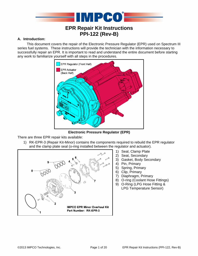
Electronic Pressure Regulator (EPR)
There are three EPR repair kits available: 1) RK-EPR-3 (Repair Kit-Minor) contains the components required to rebuild the EPR regulator
and the clamp plate seal (o-ring installed between the regulator and actuator). 1) Seal, Clamp Plate 2) Seat, Secondary 3) Gasket, Body Secondary 4) Pin, Primary 5) Spring, Primary 6) Clip, Primary 7) Diaphragm, Primary 8) O-ring (Coolant Hose Fittings) 9) O-Ring (LPG Hose Fitting &
LPG Temperature Sensor)

©2013 IMPCO Technologies, Inc. Page 2 of 20 EPR Repair Kit Instructions (PPI-122, Rev-B)
2) RK-EPR-4 (Repair Kit-Major) contains a new EPR regulator completely assembled and ready to install onto the EPR actuator and includes the Clamp Plate Seal.
1) Regulator, EPR 2) Seal, Clamp Plate 3) O-ring (Coolant Hose Fittings) 4) O-Ring (LPG Hose Fitting & LPG
Temperature Sensor)
3) RK-EPR-5 (Repair Kit-EPR Diaphragm) contains the components necessary to replace the EPR
actuator diaphragm. 1) Diaphragm, EPR 2) Screw, EPR Diaphragm 3) Seal, EPR Balance Port
B. Important Notices, Notes, Cautions & Warnings:
READ ALL IMPORTANT NOTICES, NOTES, CAUTIONS AND WARNINGS BEFORE STARTING ANY PROCEDURE
Always inspect the major casting pieces for damage, leaks, corrosion or cracks before attempting
a service repair. Replace the EPR as an assembly if any conditions with the actuator portion are found.
Always wear approved eye and face protection, protective clothing and gloves when working on
fuel and coolant systems and on or around batteries. Failure to heed this caution may result in blindness or bodily injury.
Always wear approved eye and face protection when using aerosol cleaning or lubricating products and only use the products in a well ventilated area away from sparks, flames and heat sources. Failure to
heed this caution may result in eye injury or a fire.

©2013 IMPCO Technologies, Inc. Page 3 of 20 EPR Repair Kit Instructions (PPI-122, Rev-B)
Any maintenance, service or repair should be performed by trained and experienced service
technicians. Proper tools and equipment should be used to prevent injury to the servicing technician or damage to property or system components. Service repairs should always be performed in a safe environment and the technician should always wear protective clothing and eyewear to prevent injury. Failure to heed this warning could result in serious bodily injury, death and/or severe property damage.
Do not use Teflon tape to seal any fuel fittings. Fragments of the tape may enter into the fuel
system, causing damage or malfunctions of critical fuel system components that may result in serious bodily injury and/or property damage.
The Repair Kits consist of the only serviceable components for the Spectrum III EPR. Do not use
any other components or regulator repair kits to service the Spectrum III EPR. The Kits are specifically designed for the Spectrum III EPR and are not compatible with other regulators. Failure to heed this warning could result in serious bodily injury, death or severe property damage.
Even after releasing pressure in fuel lines, residual vapor pressure will be present in the fuel
system. Ensure the work area is well ventilated away from sparks, flames and heat sources before disconnecting any fuel line or fitting.
Care must be taken when removing the regulator from the actuator to prevent damage to the
lever, the actuator diaphragm and the diaphragm plate. The lever and the diaphragm plate are not serviceable and (if damaged) the entire EPR must be replaced.
Never use silicone based lubricants or sealing compounds on any component related to the fuel
system. The use of silicone based compounds will contaminate the oxygen sensors and render them useless. Use only lubricants and sealing compounds labeled “O2 sensor safe”.

©2013 IMPCO Technologies, Inc. Page 4 of 20 EPR Repair Kit Instructions (PPI-122, Rev-B)
SERVICE TECHNICIANS AND USERS SHOULD CAREFULLY READ AND ABIDE BY THE PROVISIONS SET FORTH IN NATIONAL FIRE PROTECTION ASSOCIATION PAMPHLET #37 FOR STATIONARY ENGINES, #52 FOR CNG VEHICULAR FUEL SYSTEMS OR #58 FOR LPG SYSTEMS. INSTALLERS LPG INSTALLATIONS IN THE UNITED STATES MUST BE DONE IN ACCORDANCE WITH FEDERAL STATE OR LOCAL LAW, WHICHEER IS APPLICABLE AND NATIONAL FIRE PROTECTION ASSOCIATION PAMPHLET #58, STANDARD FOR STORAGE AND HANDLING OF LIQUEFIED PETROLEUM GASES TO THE EXTENT THESE STANDARDS ARE NOT IN VIOLATION WITH FEDERAL, STATE OR LOCAL LAW. IN CANADA REFER TO CAN/CGA PROPANE INSTALLATION CODES. CNG INSTALLATIONS IN THE UNITED STATES MUST RE DONE IN ACCORDANCE WITH FEDERAL STATE OR LOCAL LAW AND NATIONAL FIRE PROTECTION ASSOCIATION PAMPHLET #52, COMPRESSED NATURAL GAS (CNG) VEHICULAR FUEL SYSTEMS TO THE EXTENT THESE STANDARDS ARE NOT IN VIOLATION WITH FEDERAL, STATE OR LOCAL LAW. IN CANADA REFER TO CAN/CGA CNG INSTALLATION CODES. LPG AND/OR NATURAL GAS INSTALLATIONS ON STATIONARY ENGINES MUST RE DONE IN ACCORDANCE WITH FEDERAL, STATE OR LOCAL LAW AND NATIONAL FIRE PROTECTION ASSOCIATION PAMPHLET #37, STATIONARY COMBUSTION ENGINES AND GAS TURBINE ENGINES, TO THE EXTENT THESE STANDARDS ARE NOT IN VIOLATION WITH FEDERAL, STATE OR LOCAL LAW. FAILURE TO ABIDE BY THE ABOVE WILL VOID ANY IMPCO WARRANTY ON THE PRODUCTS AND MAY CAUSE SERIES INJURY OR PROPERTY DAMAGE. DUE TO THE INHERENT DANGER OF GASEOUS FUELS THE IMPCO PRODUCTS SHOULD NOT BE INSTALLED OR USED BY PERSONS NOT KNOWLEDGEABLE OF THE HAZARDS ASSOCIATED WITH THE USE OF GASEOUS FUELS.

©2013 IMPCO Technologies, Inc. Page 5 of 20 EPR Repair Kit Instructions (PPI-122, Rev-B)
C. Required tools and chemicals:
1) Torx 6-point standard bits (TX15 & TX20) 2) Torx 5-point tamper resistant bit (20IPR) 3) #2 Phillips screwdriver & ¼” drive bit 4) Small (toothbrush size) fine bristled brass
or bronze brush 5) ¼” drive ratchet 6) ¼” drive torque wrench (in-lb / Nm) 7) ¼” drive 4” extension 8) ¼” drive ¼” socket 9) Needle-nose pliers 10) Coolant hose clamps 11) Small flat-blade screwdriver (pocket style) 12) Safety solvent or aqueous solution
cleaning fluid (or equivalent) 13) Electronic or brake parts aerosol cleaner 14) Liquid Wrench aerosol penetrating oil
(L112) or equivalent (DO NOT use WD-40 or other water displacement products)
15) Loctite 263 thread locker
D. EPR Removal from Forklift:
Read all Important Notices, Notes, Cautions and
Warnings before starting any procedure.
Refer to the manufacturer’s service manual procedures for complete details: 1) Turn the LPG tank manual valve OFF. 2) Start the engine and let it run until it stalls. 3) Restart the engine until it will not restart. 4) Disconnect the battery negative cable. 5) Disconnect the EPR electrical connector. 6) Clamp off the two EPR coolant hoses 2-3
inches from the EPR fittings.
7) Remove the four EPR coolant and fuel hose / temperature sensor retaining clips.
8) Remove the coolant hose fittings from the EPR.
9) Remove the fuel hose fitting and fuel temperature sensor from the EPR.
10) Disconnect the LPG line from the lockoff. 11) Disconnect the lockoff electrical connector. 12) Remove the lockoff from the regulator. 13) Remove the three nuts securing the EPR
and remove the EPR from the forklift. 14) Carefully inspect the outside of the EPR
assembly for cracks, signs of leakage, corrosion, stripped threads, dents or damage. If any damage is found, the EPR assembly must be replaced.

©2013 IMPCO Technologies, Inc. Page 6 of 20 EPR Repair Kit Instructions (PPI-122, Rev-B)
E. EPR Regulator Removal:
Read all Important Notices, Notes, Cautions and Warnings before starting any
procedure. 1) Thoroughly clean the EPR around the
actuator / regulator mating surfaces with a brass brush and an aerosol cleaner (brake cleaner, electrical contact cleaner, etc.).
• DO NOT use carburetor cleaner. • Tape over the EPR electrical connector
and any exposed balance line port to protect them from dirt and debris intrusion.
2) Place the EPR assembly (with the
regulator face down) on a flat workbench and remove the six regulator retaining screws with a Torx TX20 tool bit.

©2013 IMPCO Technologies, Inc. Page 7 of 20 EPR Repair Kit Instructions (PPI-122, Rev-B)
3) Very carefully separate the regulator from the actuator.
The regulator secondary lever is inserted into a slot in the actuator diaphragm plate. The regulator MUST be moved in the direction illustrated while separating from the actuator to slip the lever out of the plate slot. If the diaphragm plate is damaged, the EPR assembly must be replaced.
Cracked Diaphragm Plate Slot
4) Thoroughly inspect the diaphragm plate slot for any cracking, distortion or other damage.
5) Replace the EPR assembly if the plate is damaged.
Deformed EPR Diaphragm
6) Inspect the EPR diaphragm for excessive oil / heavy end contamination and/or deformation.
7) Replace the diaphragm if it is saturated with oil / heavy ends or deformed (refer to sections H & I).

©2013 IMPCO Technologies, Inc. Page 8 of 20 EPR Repair Kit Instructions (PPI-122, Rev-B)
1) If the regulator is going to be replaced with a new assembly (RK-EPR-4) AND the EPR diaphragm
requires replacing, go to section H (EPR Diaphragm Removal). 2) If the regulator is going to be replaced with a new assembly (RK-EPR-4) AND the EPR diaphragm
does not require replacing, go to section J (EPR Regulator Installation). F. EPR Regulator Disassembly:
Read all Important Notices, Notes, Cautions and Warnings before starting any
procedure. 1) Using a Torx TX20 tool bit, remove the
secondary lever, spring and pin. 2) Remove the secondary seat seal from the
lever and discard the seal.
DO NOT discard the lever, spring or pin.
3) Inspect the lever pin holes for deformation
or damage. 4) Inspect the pin for wear or damage. 5) If either the lever or the pin is worn or
damaged, the regulator will have to be replaced as an assembly (RK-EPR-4).
6) Inspect the secondary seat for wear or
damage. 7) If the seat is worn or damaged, the
regulator will have to be replaced as an assembly (RK-EPR-4).

©2013 IMPCO Technologies, Inc. Page 9 of 20 EPR Repair Kit Instructions (PPI-122, Rev-B)
8) Using a Torx 20IPR tool bit, remove the seven regulator cover screws.
9) Remove the cover and the primary
diaphragm. 10) Discard the diaphragm. 11) Inspect the cover fulcrum for wear, cracks
or damage. 12) Replace the regulator as an assembly
(RK-EPR-4) if the fulcrum is worn or damaged.
13) Remove the separator plate and gasket.
14) Discard the gasket.

©2013 IMPCO Technologies, Inc. Page 10 of 20 EPR Repair Kit Instructions (PPI-122, Rev-B)
15) Using a small, flat-bladed screw driver, remove and discard the primary seat pin, spring and circlip.
16) Inspect the primary seat for wear, cracks or
damage. 17) Replace the regulator as an assembly
(RK-EPR-4) if the seat is worn or damaged.

©2013 IMPCO Technologies, Inc. Page 11 of 20 EPR Repair Kit Instructions (PPI-122, Rev-B)
G. EPR Regulator Reassembly:
Read all Important Notices, Notes, Cautions
and Warnings before starting any procedure.
1) Thoroughly clean the regulator parts with safety solvent or aqueous cleaning solution.
2) Remove the gasket material with a fine bristled brass or bronze brush.
DO NOT use a steel wire brush or heavy bristled brush as they can scratch the aluminum surfaces and may lead to a fuel leak.
3) Inspect all gasket surfaces for scratches, cracks or damage.
4) Replace the regulator as an assembly (RK-EPR-4) if any gasket surface problems are found.
5) Insert the new primary seat pin into the
separator plate and set the spring in place. 6) Using a pair of needle nose pliers, depress
the spring and set the circlip into the groove as illustrated.
7) Finish installing the circlip with the needle
nose pliers.

©2013 IMPCO Technologies, Inc. Page 12 of 20 EPR Repair Kit Instructions (PPI-122, Rev-B)
8) Install the separator gasket onto the separator plate as illustrated.
9) Set the separator plate onto the regulator
body being careful not to disturb the gasket.
Check all around the separator plate to ensure the gasket did not get folded under the plate. Failure to heed this caution will result in a gas leak that may cause a fire.

©2013 IMPCO Technologies, Inc. Page 13 of 20 EPR Repair Kit Instructions (PPI-122, Rev-B)
10) Set the primary diaphragm in place as illustrated.
11) Set the primary cover in place and (using a
Torx 20IPR tool bit) thread in all seven screws hand tight.
12) While pressing down on the cover with
your hand, continue tightening the screws evenly and in the sequence illustrated until each screw is just snug.
NOTE: As the screws are being tightened, the primary diaphragm is depressing the primary seat spring. Therefore, it is important to snug the screws evenly and in the sequence shown to alleviate distorting the cover or diaphragm plate.
13) Torque the screws to 40 in-lbs (4.5 Nm) in
sequence.

©2013 IMPCO Technologies, Inc. Page 14 of 20 EPR Repair Kit Instructions (PPI-122, Rev-B)
14) Install the new secondary valve seat seal onto the secondary lever.
15) Install the secondary pin, lever and spring
as illustrated and (using a Torx TX20 bit) torque the screw to 40 in-lbs (4.5 Nm).
Make sure the spring is seated squarely on the body and lever spring bosses as illustrated.
H. EPR Diaphragm Removal (Optional):
Read all Important Notices, Notes, Cautions and Warnings before starting any
procedure. 1) Remove and discard the EPR diaphragm
clamp plate o-ring. 2) Using a #2 Phillips screwdriver, remove the
four EPR diaphragm plate screws.
The screws are secured with a permanent thread locker and will require the use of a penetrating oil to successfully remove them. If any screw begins to tighten as it is being removed, STOP! Follow the instructions in steps 3 to 8 EXACTLY. If a screw is broken off inside the EPR actuator spring tower, the EPR will have to be replaced as an assembly.

©2013 IMPCO Technologies, Inc. Page 15 of 20 EPR Repair Kit Instructions (PPI-122, Rev-B)
3) With the problem screws loosened to the point where they just began to tighten up, spray a liberal amount of Liquid Wrench aerosol penetrating oil (L112) or equivalent) on each of the screws as illustrated.
DO NOT use WD-40 or other water displacement solvent / penetrate. These products will not work as efficiently as products specifically designed for this purpose. 4) Allow the penetrating oil to soak for at least
two minutes.
5) Turn one of the affected screws clockwise
until it is just snug. 6) Turn the screw counterclockwise 1/8 turn
past where the screw first began to tighten up.
7) Turn the screw clockwise 1/2 turn (or until just snug) and spray some more penetrate and allow it to soak in for another minute or two.
8) Repeat this procedure until the screw is removed. UNDER NO CIRCUMSTANCES should any screw be forced.
9) Repeat these steps for any additional screws.
10) Using a Torx TX15 tool bit, remove the
three screws securing the EPR clamp plate.

©2013 IMPCO Technologies, Inc. Page 16 of 20 EPR Repair Kit Instructions (PPI-122, Rev-B)
11) Remove and discard the EPR diaphragm and balance port seal (arrow).
DO NOT allow any dirt or debris to enter the EPR actuator interior.

©2013 IMPCO Technologies, Inc. Page 17 of 20 EPR Repair Kit Instructions (PPI-122, Rev-B)
I. EPR Diaphragm Installation (Optional):
Read all Important Notices, Notes, Cautions
and Warnings before starting any procedure.
1) Using an aerosol electronic cleaner with a tube inserted into the nozzle, turn the EPR actuator face down and spray a little of the product in each of the four screw holes as illustrated.
2) Set the EPR diaphragm in place (gray,
fabric side down) and install the balance port seal.
The EPR diaphragm screw holes are asymmetrical and the diaphragm can only be installed one way (as illustrated in the left photo). Improper installation of the diaphragm (as illustrated below) will cause the diaphragm to distort and not function as designed.

©2013 IMPCO Technologies, Inc. Page 18 of 20 EPR Repair Kit Instructions (PPI-122, Rev-B)
3) Install the clamp plate over the diaphragm and (using a Torx TX15 tool bit) hand-tighten the three screws.
4) Torque the screws to 10-13 in-lbs (1.1-1.5 Nm).
Make sure the diaphragm is seated in its groove completely before installing the clamp plate.
5) Set the diaphragm plate on top of the
diaphragm making sure all four of the screw holes are aligned.
As with the diaphragm, the diaphragm plate is asymmetrical and can only be installed one way.
6) Apply a little Loctite 263 thread locker to
the four diaphragm screws and install them.
7) Torque the screws to 5-9 in-lbs
(0.6-1.0 Nm) in a cross pattern as illustrated.

©2013 IMPCO Technologies, Inc. Page 19 of 20 EPR Repair Kit Instructions (PPI-122, Rev-B)
J. EPR Regulator Installation:
Read all Important Notices, Notes, Cautions
and Warnings before starting any procedure.
1) Install the clamp plate / regulator o-ring (arrow).
2) Slide the regulator in place ensuring the
secondary lever slips into the diaphragm plate slot as illustrated.
DO NOT pull the regulator away from the actuator as illustrated. The photo is for illustration purposes only and any excessive force may damage the plate slot or actuator.
3) Install the six regulator screws and (using a
Torx TX20 tool bit) hand-tighten the screws.
4) Torque the screws to 44-46 in-lbs (5.0-5.2 Nm) in the sequence illustrated.

©2013 IMPCO Technologies, Inc. Page 20 of 20 EPR Repair Kit Instructions (PPI-122, Rev-B)
K. EPR Installation:
Read all Important Notices, Notes, Cautions and Warnings before starting any
procedure. 1) Referring to the manufacturer’s service
manual procedures, installation of the EPR is the reverse order of the removal.
2) Leak test the entire fuel system (in a well ventilated area away from sparks, flames or heat sources) with approved electronic leak test equipment and/or snoop before starting the engine.
3) After test running the engine, let it cool down and check the coolant level. (Top-off the coolant if necessary).
The coolant hose fittings, fuel hose fittings and LPG temperature sensor retainer pins have a turned-in nose that must be securely installed into the holes in the regulator body as illustrated.
PPI-122
Rev-B 6/19/2013 Copyright © 2013 IMPCO Technologies, Inc. All rights reserved. Reproduction by any means, electronic or mechanical, including photocopying, recording, or by any information storage and retrieval system or translation in whole or part is not permitted without written authorization from IMPCO Technologies, Inc. Created and published by IMPCO Technical Publications