eps-gw-gl-700 rev 1 revision history - nuclear … pdfs...revision history revision 1 eps-gw-gl-700...
TRANSCRIPT

Revision History Revision 1
EPS-GW-GL-700 Page 1 of 30 Revision 1
This document has been revised to include changes to our standard design that are a result of Westinghouse design finalization reviews and changes committed to US NRC resulting from their review. The NRC changes are those changes identified as of September 2009 and reflect the proposed revision 18 to the US DCD that will be submitted mid 2010. In addition, this European DCD revision includes specific changes requested for a European AP1000. These changes include adding additional redundancy and separation to the AP1000 standard Normal Residual Heat Removal System, Component Cooling Water System, Service Water System, Spent Fuel Cooling, increasing of power of Main feedwater pumps from 3 pumps @ 33.33% to 3 pumps at 50% and a change of Reactor Coolant Pump vendor.
Change Number
Chapter Number
Section/Table/ Figure Numbers Description Reason for Change
1 6 9
Table 6.4-1 Section 9.3.2.2.2 Section 9.3.2.2.3
Revised table "ONSITE CHEMICALS" to indicate that hydrogen is stored onsite in both liquid and gas phases. The table indicates only gas at this time. SNC-AA - If we refer to a commitment from WEC in a response (See Note that DCD Table 6.4-1 is expected to be revised by Westinghouse to include the line item for hydrogen in the liquid state), I think we need something more firm or definitive to allow NRC to track the change. Do we have an RAI response number, WEC letter number for a voluntary response or other that would allow us to identify it as a unique DCD change number for NRC? Additionally, if this wording stays intact, should say "to be revised".
10 CFR 52.63 Justification: (v) Is necessary to correct material errors in the certification information PI-014 COLA Review Process-12/8/08; WEC to address.

Revision History Revision 1
EPS-GW-GL-700 Page 2 of 30 Revision 1
Change Number
Chapter Number
Section/Table/ Figure Numbers Description Reason for Change
2 1 3 5 9 10 14 16 17 18 19 21
Reg Guide 1.93 Table 1.1-1 (Shs 1,2,3/4) Table 1.6-1 (Sh 4/20) Section 3.7.3.13.4.3 Section 3.8.3.5.7 Section 3.8.4.5.3 Section 3.8.4.5.4 Section 3.8.5.4.3 Section 3.8.5.4.4 Section 3.8.5.5.5 Section 3.10 Section 3B.2.6 Table 3.8.2-5 Section 5.4.7.2 Table 5.4-17 Table 9.2.1-1 Table 9A-3 (Shs 12,24/44) Section 9A.3.6.2 Section 10.2.2.1 Table 10.1-1 Table 10.2-1 Table 10.3.2-1 Section 14.2.9.4.9 Table 17.4-1 (Sh 1/8) Section 18.8 Section 19.1.7 Section 19.59.6.1 Section 19.59.6.2
Table 1.1-1: Sh 1- Delete "n" from American Sh 2 - In-containment - lower case and hyphen Sh 2 - Add GRCA Sh 2 - Add Criterion Sh 3 - Add "s" to Motor operated valves Table 1.6-1: Revision 1 to Revision 2 Section 3.7.3.13.4.3 Third and fourth bullets should be combined into one bullet. Section 3.8.4.5.4 - correct metric conversions Section 3.8.5.4 - grammatical error - change "do" to "does Section 3.8.5.5.5 - correct metric conversion Section 3.10.1.1 - reference renumbering Section 3B.2.6 - typo - "vavle" to "valves" Table 3.8.2-5 - correct metric conversions Section 5.4.7.2 - change inside-containment to in-containment Table 5.4.17 - change note to read (Subsection 5.4.9.3) Table 9.2.1-1 - change "is" to "in" in second column Table 9A-3 - Table entries out of order and fire area zone 6030AF603214 should be 6030AF60324 Change - add S to Shaft/Machine Room Section 10.2.2.1 - consistency Table 10.1-1 - consistency Table 10.2-1 - consistency Table 10.3.2-1 - consistency Section 14.2.9.4.9 - move "and" to before blower Section B 3.2.5 - RTD should be RTP Table 17.4-1 - type in title - delete "DCD" Section 18.8 - change Probability to Probabilistic Section 19.1.7 – add reference
Errata
Revision History Revision 1
EPS-GW-GL-700 Page 3 of 30 Revision 1
Change Number
Chapter Number
Section/Table/ Figure Numbers Description Reason for Change
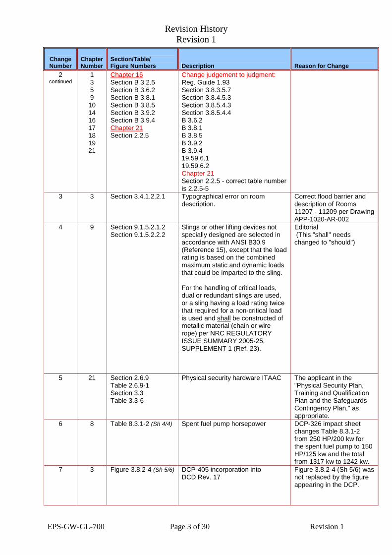
2 continued
1 3 5 9 10 14 16 17 18 19 21
Chapter 16 Section B 3.2.5 Section B 3.6.2 Section B 3.8.1 Section B 3.8.5 Section B 3.9.2 Section B 3.9.4 Chapter 21 Section 2.2.5
Change judgement to judgment: Reg. Guide 1.93 Section 3.8.3.5.7 Section 3.8.4.5.3 Section 3.8.5.4.3 Section 3.8.5.4.4 B 3.6.2 B 3.8.1 B 3.8.5 B 3.9.2 B 3.9.4 19.59.6.1 19.59.6.2 Chapter 21 Section 2.2.5 - correct table number is 2.2.5-5
3 3 Section 3.4.1.2.2.1 Typographical error on room description.
Correct flood barrier and description of Rooms 11207 - 11209 per Drawing APP-1020-AR-002
4 9 Section 9.1.5.2.1.2 Section 9.1.5.2.2.2
Slings or other lifting devices not specially designed are selected in accordance with ANSI B30.9 (Reference 15), except that the load rating is based on the combined maximum static and dynamic loads that could be imparted to the sling. For the handling of critical loads, dual or redundant slings are used, or a sling having a load rating twice that required for a non-critical load is used and shall be constructed of metallic material (chain or wire rope) per NRC REGULATORY ISSUE SUMMARY 2005-25, SUPPLEMENT 1 (Ref. 23).
Editorial (This "shall" needs changed to "should")
5 21 Section 2.6.9 Table 2.6.9-1 Section 3.3 Table 3.3-6
Physical security hardware ITAAC The applicant in the "Physical Security Plan, Training and Qualification Plan and the Safeguards Contingency Plan," as appropriate.
6 8 Table 8.3.1-2 (Sh 4/4)
Spent fuel pump horsepower DCP-326 impact sheet changes Table 8.3.1-2 from 250 HP/200 kw for the spent fuel pump to 150 HP/125 kw and the total from 1317 kw to 1242 kw.
7 3 Figure 3.8.2-4 (Sh 5/6)
DCP-405 incorporation into DCD Rev. 17
Figure 3.8.2-4 (Sh 5/6) was not replaced by the figure appearing in the DCP.

Revision History Revision 1
EPS-GW-GL-700 Page 4 of 30 Revision 1
Change Number
Chapter Number
Section/Table/ Figure Numbers Description Reason for Change
9 2 Figure 5.1-5 (Sh 1/3)
Revision to RCS Hot Leg Flow Transmitter Tag Numbers
Update with latest information.
10 9 Figure 9.3.6-1 (Sh 1/2)
AP1000 Section VII Relief Valve Design Changes
Update with latest information.
13 6 Section 6.5.2.1.1 Revise the text to indicate that valve V701 is normally closed.
The text in 6.5.2.1 was changed to indicate that valve V701 is a normally closed valve. The mark-ups are based on DCD Rev. 16 and are included in DCD Rev. 17. Note: Figure 9.5.1-1 Sh 3 was changed in Rev. 17.
15 16 Table 3.3.1-1 Table 3.3.2-1 Section 5.5.7 Section B 3.1.9 Section B 3.4.1 Section B 3.6.6 Section B 3.6.8 Section B 3.6.9 Section B 3.7.10 Section B 3.8.5 Table B.3.8.5-1
Table 3.3.1-1 - add other to header Table 3.3.2-1 - Page 9 header spacing Section 5.5.7 - "ensure" to "ensures" Section B 3.1.9 - "signalled" to "signaled" Section B 3.4.1 - "loadchanges" to "load changes" Section B 3.6.6 - "these" to "this" Section B 3.6.8 - "a accident" to "an accident" Section B 3.6.9 - "dash" to a "dot" Section B 3.7.10 - "Reference 6" to "Reference 3" Section B 3.8.5 - "Reference 3" to Table B 3.8.5 - center Table Heading
Editorial
18 16 TS 1.1 GRCA treatment in Shutdown margin calculation
Revised TS SHUTDOWN MARGIN Definition paragraph c. Spelled out acronym GRCA in definition for SHUTDOWN MARGIN paragraph c.
19 7 Table 7.5-1 (Sh 2/12)
Minimum number of core exit thermocouples per core quadrant.
Revise to reflect the minimum number of core exit thermocouples as described in Table 3.3.3-1 and Section B3.3.3 of the AP1000 Technical Specifications.

Revision History Revision 1
EPS-GW-GL-700 Page 5 of 30 Revision 1
Change Number
Chapter Number
Section/Table/ Figure Numbers Description Reason for Change
20 16 TS 3.1.4 B 3.1.4 TS 3.1.5 B 3.1.5 TS 3.1.6 B 3.1.6
OPDMS-operating Tech Specs TS 3.1.5 and TS 3.1.6 are revised to clarify the exclusion of applicability with respect to OPDMS operability.
21 16 TS Table 3.3.1-1 (Sh 2/6) TS B 3.3.1
Reactor Trip System Instrumentation
Functions 6, 7 and 12 in Table 3.3-1 are marked up to be consistent with Table 7.2-2 in DCD.
22 1 15
Table 1.6-1 (Sh 14/20) Section 15.2.2 Section 15.2.10
Pressurizer Safety Valves Revised DCD to cite the same reference concerning overpressure protection in Section 15.2.2 and Table 1.6-1.
23 16 B 3.6.9 Reference 3 is not discussed in the Bases and is not needed.
Deletion of Reference 3
24 16 B 3.7.2 B 3.7.6 B 3.7.11 B 3.7.12
Delete and add references. B3.7.2 - provide a reference to Reference 4. B3.7.6 - provide a reference to Reference 2 and 5. B3.7.11 and B3.7.12 - Revision numbers are not necessary as the most recent revision is the one implied.
25 9 16
Section 9.1.2.2.1 Figure 9.1-3 (Shs 1,2/2) Chapter 16 TS Figure 4.3-2
Fuel rack cell spacing explanation Note: CN 125 handles Chapter 16 changes.
Added Detective Fuel Assembly Storage Cell nominal center to center spacing of 11.62 inches in Section 9.1.2.2.1 of the DCD. Corrected significant digits of nominal center to center spacing value in Section 9.1.2.2.1 and Figure 9.1-3. TS 4.3.1.1(f) is replaced with a new paragraph describing the two fuel assembly storage configurations.
26 9 16
Section 9.1.1.3 Chapter 16 TS 4.3.1.2 (b. and c.) of Section 16.1
Keff differences for the new fuel storage racks.
Modify to consistently reflect the correct terminology.
27 16 TS 5.5.4 SG tube inspection schedule Revise Steam Generator Program to state "Inspect 100% of the tubes in each SG during the first refueling outage following installation."

Revision History Revision 1
EPS-GW-GL-700 Page 6 of 30 Revision 1
Change Number
Chapter Number
Section/Table/ Figure Numbers Description Reason for Change
28 3 Table 3.9-15 WESTEMS code Insert missing code into table.
29 16 TS 1.4 Frequency
Erroneous example in TS Westinghouse agrees with TSTF-485 for the AP1000. Revise example 1.4-1 to make it consistent with requirements specified in in SR 3.0.2 and SR 3.0.4.
30 16 B 3.6.4 Containment Pressure In Bases Clarify the Bases regarding the maximum peak containment pressure.
31 16 SR 3.1.1.1 Bases and SR inconsistency. Bases will be modified to be consistent with NUREG 1431 by the addition of "with Keff with > 1.0"
32 16 TS 3.1.8 B 3.1.8
PHYSICS TESTS Exceptions – MODE 2 Bases
Resolve discrepancy between LCO 3.1.8 c, SR 3.1.8.3 and the Analytical Safety Analyses Section of BASES. The PHYSICS TEST EXCEPTIONS - MODE 2 discrepancies are resolved by changing the "<" sign to "<" for all occurrences. The changes are consistent with the STS.
33 16 B 3.1.7 Required Action and Bases inconsistency.
The Action A.1 Bases are corrected by changing "B.1 or B.2" to "C.1 or C.2" This change makes the Action A.1 DCD Bases statement identical to the STS Bases.
34 16 B 2.1.1 Use of term "Reactor Protection System" (RPS)
The acronym RPS (Reactor Protection System) is no longer used and has been replaced by Protection and Safety Monitoring System (PMS).
35 16 B 3.2.3 Identify reference use. Reference 2 is added to the third Applicable Safety Analysis paragraph to be consistent with the STS.
36 16 Section 3.3.1 -- Table 3.3.1-1 (Sh 5/6)
Inconsistent Definitions and LCO Table numbers.
Page break was removed. Definitions were corrected. LCO Table numbers adjusted accordingly.

Revision History Revision 1
EPS-GW-GL-700 Page 7 of 30 Revision 1
Change Number
Chapter Number
Section/Table/ Figure Numbers Description Reason for Change
37 16 B 3.4.3, References Erroneous reference. Reference 5 is changed to be "Regulatory Guide 1.99."
38 3 Table 3.8.4-2 Identify load combinations. For consistency, the DCD table will be revised to include earth pressure in Table 3.8.4-2. New DCD load combinations (10,11) will be added applicable to the design of the nuclear island basemat.
39 2 Section 2.5.4.3 Table 2.5-1
Settlement Criteria Requirements. DCD subsections 2.5.4.3 and 2.5.4.6.11 are revised to clearly explain settlement criteria requirements.
40 2 Section 2.5.4.6.2 Define compaction standards. Second paragraph of subsection 2.5.4.6.2 will be revised to indicate that for medium sand a blow count greater than 10 blows per foot, or for dense sand a blow count greater than 30 blows per foot is representative of acceptable backfill.
41 3 Section 3.8.4.1.1 Section 3.8.4.4.1 Section 3.8.4.5.4 Section 3.8.4.6.1.1 Section 3.8.4.8 Section 3H.5.1.5 Section 3H.5.6 Table 3.8.4-6 Figure 3.8.4-3 Figure 3H.5-11 (Shs 6,7/7)
Shield building Incorporate multiple changes.
42 3 Section 3.6.2.5 Section 3.6.4.1
Clarify the basis for determination of high energy and intermediate break locations.
Revise sections on "Verification of the Pipe Break Hazard Analysis" and "Pipe Break Hazard Analysis"
43 16 B 3.5.1 Accumulators Revise TS bases B 3.5.1 to specify the number of accumulators.

Revision History Revision 1
EPS-GW-GL-700 Page 8 of 30 Revision 1
Change Number
Chapter Number
Section/Table/ Figure Numbers Description Reason for Change
44 16 B 3.1.8 ANSI/ANS-19.6.1 edition year Revise code reference to the 2005 version.
45 16 B 3.4.6.1 (SR 3.4.6.1 and References)
Relief valve lift setpoint requirements.
Revise Bases for TS SR 3.4.6.1 to indicate +/- 1% OPERABILITY range.
46 16 TS 3.5.4 B 3.5.4 B 3.5.8
Page B3.5.2 - delete "4" to read "in Modes 1,2, and 3" Page 3.5.4-3 - delete "System level" Page 3.5.4-3 - delete "or the LCO is not met for reasons other than…." Page B3.5.8-1 - change from closed to open
Editorial
47 16 B 3.7.1 TS Table 3.7.1-2
Justify setpoint setting of MSSVs tolerance change
Table 3.7.1-2 of TS 3.7.1 and the Bases for SR 3.7.1.1 will be revised to indicate +/- 1% OPERABILITY range for the main steam safety valve lift settings to be consistent with SR 3.4.7.1.
48 16 B 3.9.1 Explain Boron Concentration changes
Due to technical differences between previous plant design and the passive AP1000 plant design, the Bases for TS 3.9.1 are revised and GDC 26 added as Reference 3.
49 3 Section 3.7.3.8.1 Appendix 3C.1.5
Branch Lines Coupling In Reactor Coolant Loop Analysis
DCD Section 3.7.3.8.1 and Appendix C are revised to clearly differentiate the analysis of loop piping and branch line piping.
50 11 Section 11.5 Continuous effluent monitors conformance to ANSI N42.18-2004
Revise DCD consistent with internal documentation - design conforms to ANSI-N42.18-1980.G33.
Revision History Revision 1
EPS-GW-GL-700 Page 9 of 30 Revision 1
Change Number
Chapter Number
Section/Table/ Figure Numbers Description Reason for Change
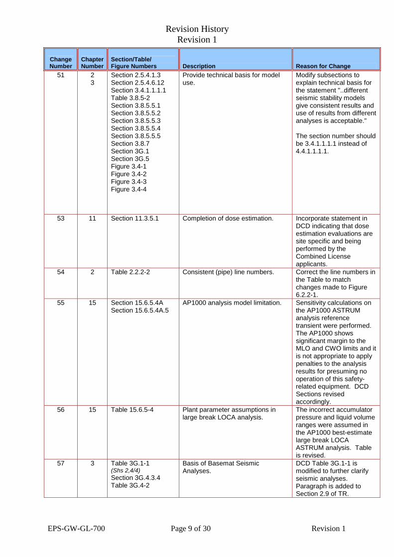
51 2 3
Section 2.5.4.1.3 Section 2.5.4.6.12 Section 3.4.1.1.1.1 Table 3.8.5-2 Section 3.8.5.5.1 Section 3.8.5.5.2 Section 3.8.5.5.3 Section 3.8.5.5.4 Section 3.8.5.5.5 Section 3.8.7 Section 3G.1 Section 3G.5 Figure 3.4-1 Figure 3.4-2 Figure 3.4-3 Figure 3.4-4
Provide technical basis for model use.
Modify subsections to explain technical basis for the statement "..different seismic stability models give consistent results and use of results from different analyses is acceptable." The section number should be 3.4.1.1.1.1 instead of 4.4.1.1.1.1.
53 11 Section 11.3.5.1 Completion of dose estimation. Incorporate statement in DCD indicating that dose estimation evaluations are site specific and being performed by the Combined License applicants.
54 2 Table 2.2.2-2 Consistent (pipe) line numbers. Correct the line numbers in the Table to match changes made to Figure 6.2.2-1.
55 15 Section 15.6.5.4A Section 15.6.5.4A.5
AP1000 analysis model limitation. Sensitivity calculations on the AP1000 ASTRUM analysis reference transient were performed. The AP1000 shows significant margin to the MLO and CWO limits and it is not appropriate to apply penalties to the analysis results for presuming no operation of this safety-related equipment. DCD Sections revised accordingly.
56 15 Table 15.6.5-4 Plant parameter assumptions in large break LOCA analysis.
The incorrect accumulator pressure and liquid volume ranges were assumed in the AP1000 best-estimate large break LOCA ASTRUM analysis. Table is revised.
57 3 Table 3G.1-1 (Shs 2,4/4) Section 3G.4.3.4 Table 3G.4-2
Basis of Basemat Seismic Analyses.
DCD Table 3G.1-1 is modified to further clarify seismic analyses. Paragraph is added to Section 2.9 of TR.

Revision History Revision 1
EPS-GW-GL-700 Page 10 of 30 Revision 1
Change Number
Chapter Number
Section/Table/ Figure Numbers Description Reason for Change
58 2 Section 2.5.4.2 Inconsistency In Soil Support Adequacy Statement
Clarify description
59 14 Section 14.3.2.2 ITAAC closure exemption definition. Additional write-up at the end of 14.3.2.2 - Inspections, Tests, Analyses, and Acceptance Criteria (ITAAC).
60 16 B 3.1.4 B 3.1.8
Editorial Correction of the LCO 3.1.5 title to specify "Limits" is required.
61 15 Chapter 15 Roadmap RAI transmittal letter number Replace all DCP/NRC2209 with DCP/NRC2321 in Chapter 15 roadmap
62 16 TS 3.2.5 Bases 3.2.5
Discrepancy of Applicability Sections.
Bases fro 3.25 should read: "The OPDMS monitoring of SDM is applicable in Modes 1 and 2 with Keff >1.
63 3 Figure 3G.4-7Y Figure 3G.4-7Z
These figures should be changed to Elevation 116.50' to match the elevation on Figure 3G.4-7X
Editorial
64 9 Table 9.1-3 (Sh 1/2)
SFS info update DCD and SSD consistency
65 5 Table 5.2-3 ASME Code Case for Weld Filler Materials
Improve primary pressure boundary weld properties.
66 6 Section 6.2.4.2.3 Table 6.2.4-3
Hydrogen Igniter Temperatures
Incorrect value in DCD
68 9 Section 9.3.5.2.2 Sumps and drain tanks. Discrepancy

Revision History Revision 1
EPS-GW-GL-700 Page 11 of 30 Revision 1
Change Number
Chapter Number
Section/Table/ Figure Numbers Description Reason for Change
69 5 Table 5.2-1 (Sh 4/6)
CRDM Pressure Housing Material The design of the CRDM pressure housing uses SA-182 type F304 LN.
70 11 Section 11.2.4.3 Ion Exchange Resin Add preoperational examination of resin amount in the LWS components.
71 21 Table 2.1.2-1 Table 2.1.2-4 Table 2.2.2-1 Section 2.2.3 Table 2.2.3-4 Section 2.3.11 Table 2.3.11-2 Table 2.3.6-4
WGS Equipment Seismic Category Reflect system design change.
72 9 Section 9A.3.4.14 Table 9A-3 (Shs 19,20/44)
Cyber Security Room Address design basis threat requirements.
73 5 9 19
Section 5.3.1.1 Section 9A.3.4.3B Table 9A-3 (Sh 5/44) Section 19D.8.2.2
Various DCD updates To reflect incomplete changes identified in DCP-111, Rev. 1, Rx Flow Skirt DCP-103, Access Control Modifications DCP-116, Rev. 1, Level Sensors
74 15 Table 15A-5 Table 15A-6 and Notes
Atmospheric Dispersion Factors (X/Qs)
Provide revised radiological consequence doses with new X/Q values
75 16 TS 3.4.4 TS 3.4.8 TS 3.4.14 B 3.4.4 B 3.4.8 B 3.4.14
Low Temperature Overpressure Protection (LTOP)
Ensure consistency of LTOP requirements specified in TS3.4.4, TS3.4.8 and TS3.4.14.
76 9 Section 9.2.11.1 Change "compatibility" to "habitability"
Consistency
77 11 14
Section 11.5.2.3.3 Section 11.5.7 Section 11.5.8 Section 14.2.9.2.18
Sampling Of Airborne Radioactive Effluent
Propose an alternative approach to address the limitations of ANSI N13.1-1969.

Revision History Revision 1
EPS-GW-GL-700 Page 12 of 30 Revision 1
Change Number
Chapter Number
Section/Table/ Figure Numbers Description Reason for Change
78 11 Table 11.5-2 Rail Car Bay Area Name Provide consistent title for area rad monitor to match room title from layout drawing.
79 21 Table 3.7-1 Table 3.7-3
As-Built reliability and availability of risk-significant SSCs
Confirm as-built SSCs match the design.
80 19 Section 19.58.2.3 Section 19.58.2.3.2
Bounding Toxic Material Hazard Only cases above frequency >0.15 per year need examination through Regulatory Guide 1.78.
81 3 6
Section 3.8.2.7 Section 6.6.9.1 Section 6.6.9.2
Pre-Service And In-Service Containment Examination
The Combined License applicant will perform this according to ASME Code Section XI as described in DCD Subsection 6.6. Subsection 3.8.2.7 will be revised to reference Section 6.6.
82 3 Section 3.8.3.4 Section 3.8.3.4.1.1 Table 3.8.3-2
Containment Internal Structure Stiffness Assumptions
This was moved to DCD Section 3.7 and 3G.
83 3 Section 3I.6.4 Section 3I.7
Cyclic fatiguing of equipment Revise description of HRHF Screening Test.
84 5 Section 5.2.1.1 AP1000 piping design Add provision for 10 CFR 50.55 and NB-3220.
85 5 Table 5.2-3 ASME Code Cases Revise the entries for Code Cases N-655, N-757 and N-759.
86 Intro Table 1-1 ASME Code Cases Remove incorrect references.
87 6 Table 6.2.3-1 (Shs 1-4/4)
Location of containment isolation valves outside containment.
Provide pipe lengths to valves.
88 3 Section 3.7.5.2 Post seismic new fuel rack clearance.
Add requirement for Combined License applicants to verify clearances.

Revision History Revision 1
EPS-GW-GL-700 Page 13 of 30 Revision 1
Change Number
Chapter Number
Section/Table/ Figure Numbers Description Reason for Change
89 9 Section 9.1.1.2.1.D Section 9.1.2.2.1.E Section 9.1.4.1.1.F
New fuel handling crane Add text to state load maintenance during seismic events.
90 1 3 5 6
Table 1.9-1 (Sh 12/15) Section 3.9.8.4 Section 5.2.1.2 Section 5.2.4.3 Section 5.2.6.2 Section 6.6.3 Section 6.6.9.1
ASME Code Cases Provide Code Cases similar to those in DCD Table 5.2-3.
91 9 13
Section 9.1.5 Section 13.5.1
Heavy Load Move Path Provide drawings for COL heavy load handling program.
92 9 Section 9.1.5.3 MSIV monorail hoist load drop Revise to indicate decay heat removal equipment is not located in the load path.
93 3 Figure 3.8.3-8 (Sh 2/3)
Structural Module Connection Connector is not continuous - delete "cont" from left side of Figure 3.8.3-8, Sheet 2.
94 9 Section 9.1.6.7 Neutron Absorbing Material Provide description of Metamic as a Type 6061 aluminum alloy matrix reinforced with boron carbide.
95 3 5
Figure 3.9-8 Figure 5.3-1 Figure 5.3-5
DVI Nozzle Design Change Pictorial representation of the DVI nozzles changes, but no dimensions are affected and there are no interfacing components affected by the interior geometry change.
96 10 Table 10.1-1 Steam Generator Exit Pressure Revise value in Table 10.1-1 to 821 psig.
97 5 Section 5.4.4.3 Units of pressure differential Change "psig" for the units of pressure differential to "psi".

Revision History Revision 1
EPS-GW-GL-700 Page 14 of 30 Revision 1
Change Number
Chapter Number
Section/Table/ Figure Numbers Description Reason for Change
98 1 Appendix 1A, Reg. Guide 1.50
Criteria wording Change "pressurized water heat transfer" to "post-weld heat treat".
99 3 Section 3.8.2.4.1.1 Section 3.8.2.4.1.2 Table 3.8.2-5
Penetration Analyses Describe changes to model.
100 3 Table 3.2-3 Table 3.11-1
Additional PCS makeup line Complete changes due to valve addition.
101 3 Section 3.8.3.5.8.1 Section 3.8.3.5.8.2 Section 3.8.3.5.8.3 Section 3.8.7
Critical Sections Of Containment Internal Structures
Conform DCD text to TR-57 information and SRP level of detail.
102 14 Section 14.2.9.1.6 Control Room Air Quality Preoperational test added to show VES flowrate is sufficient to maintain proper control room air quality.
103 6 Section 6.4.4 Nuclear Island Nonradioactive Ventilation System (VBS)
Clarify area names and filtration/isolation mode actuations.

Revision History Revision 1
EPS-GW-GL-700 Page 15 of 30 Revision 1
Change Number
Chapter Number
Section/Table/ Figure Numbers Description Reason for Change
104 1 3 6 7 9 14 15 16 21
Appendix 1A, Reg. Guide 1.5.2 Table 1.9-1 (Sh 4/15) Section 1.9.4.2.2, B36 Table 3.2-3 (Shs 56-58/67) Table 3.11-1 (Shs 29,30,45,46,47/50) Section 6.4.1.1 Sections 6.4.2.1 to 6.4.2.4 Section 6.4.3.2 Section 6.4.4 Sections 6.4.5.1 Section 6.4.5.2 Section 6.4.8 Table 6.4-2 Figure 6.4-1 Figure 6.4-2 (Shs 1,2/2) Figure 7.2-1 (Shs 11,13/20) Section 7.3.1.2.17 Table 7.3-1 (Sh 7/9) Table 7.3-2(Shs 1,2/4) Section 9.4.1.1.1 Section 9.4.1.2.3.1 Table 9.5.1-1 (Sh 17/33) Table 9A-3 (Sh11/44) Section 14.2.9.1.6 Section 15.6.5.3.5 Table 15.6.5-2(Sh 2/3) Table 15.6.5-3 Chapter 16 TS 3.3.2 - Table 3.3.2-1 Tech Spec 3.7.6 Tech Spec 5.5 Tech Spec Bases 3.3.2 Tech Spec Bases 3.7.6 Chapter 21 Section 2.2.5 Table 2.2.5-1 Table 2.2.5-5 Figure 2.2.5-1
Main Control Room (MCR) Dose Analysis.
Update component descriptions, Tech Specs, and initiation, operation, and test detail.

Revision History Revision 1
EPS-GW-GL-700 Page 16 of 30 Revision 1
Change Number
Chapter Number
Section/Table/ Figure Numbers Description Reason for Change
105 3 6 8 9 21
Table 3.2-3 (Sh 53/67) Table 3.9-16 (Sh 18,19/22) Table 3.11-1 (Shs 29,45,46/50) Table 3I.6-2 (Shs 24,25/28) Table 3I.6-3 (Sh 27/31) Section 6.4.2.1 Section 6.4.2.2 Section 6.4.2.4 Figure 6.4-1 Table 8.3.2-1 Table 8.3.2-3 Section 9.4.1.2.1.1 Section 9.4.1.2.2 Section 9.4.1.2.3.1 Table 9.5.1-1 (Shs 7,8,17/33) Figure 9.4.1-1 (Shs 1-5/7) Chapter 21 Table 2.7.1-1 Figure 2.7.1-1 (Sh 1/2)
Main Control Room Pressure Boundary
Clarify boundary location and HVAC duct penetrations.
106 6 21
Section 6.1.1.4 Section 6.1.2.1.5 Section 6.1.2.1.6 Section 6.3.2.2.7.1 Section 6.3.2.2.7.2 Section 6.3.2.2.7.3 Section 6.3.8.1 Table 6.1-2 Figure 6.3-2 Chapter 21 Table 2.2.3-4 Items 8c-ix, 8c-x
Impacts to the AP1000 to address generic safety issue (GSI) - 191
The AP1000 DCD Rev. 17 is being amended to address Nuclear Regulatory Commission (NRC) Generic Letter 2004-02 in accordance with the responses to Requests for Additional Information (RAIs) from the NRC.

Revision History Revision 1
EPS-GW-GL-700 Page 17 of 30 Revision 1
Change Number
Chapter Number
Section/Table/ Figure Numbers Description Reason for Change
107 2 Section 2.5.2.1 Section 2.6
Hard Rock High Frequency Seismic Response
Instructs COL applicant having HRHF-characteristic GMRS but are not within analyzed cases, how to perform site specific studies demonstrating HF doesn't damage their site.
108 1 4 6 15
Table 1.8-2 (Sh 11/14) Section 4.3.1.3.1 Section 6.2.1.3.2.1 Section 15.0.15.1
Plant Calorimetric Power Uncertainty
Affirm AP1000 design uses a 1% uncertainty for DCD Chapters 4, 6, and 15 analyses, and indicate COL holders will validate value after equipment installation.
109 3 4
Section 3.9.4.2.2 Section 4.5.1.2
Control Rod Drive Mechanism (CRDM)
Note CRDM design and material improvements in DCD.
110 17 Table 17.4-1 (Sh 2/8)
Risk Important Components in Design Reliability Assurance Program (D-RAP)
Justify reduction in importance for four component groups.
111 9 Section 9.1.3.4.3 Spent Fuel Pool Heatup Revise differing time of heatup values for consistency.
112 3 Section 3I.6.4 Damping in Seismic Analyses Add a statement to include the HRHF SSE response spectra as input to the HRHF seismic equipment screening evaluation.
113 6 Section 6.2.1.1.1 Section 6.2.7
Containment Response Analyses Add clarifying statement that small changes have been analyzed and conclusions remain valid.
114 6 Section 6.2.1.2.1 Section 6.2.7
Pressurizer subcompartment analysis
Add clarifying statement that small changes have been analyzed and conclusions remain valid.

Revision History Revision 1
EPS-GW-GL-700 Page 18 of 30 Revision 1
Change Number
Chapter Number
Section/Table/ Figure Numbers Description Reason for Change
115 3 6 9 21
Table 3.2-3 (Sh 3/67) Table 3.9-12 (Sh 1/7) Table 3.9-16 (Sh 2/22) Table 3.11-1 (Shs 18,20,30,46,47/50) Table 6.2.3-1 (Shs 1-4/4) Section 9.3.6.3.7 Figure 9.3.6-1 (Sh 1/2) Chapter 21 Figure 2.2.1-1 Table 2.3.2-1
Overpressure relief valves used as containment isolation valves.
Incorporate changes required to add CVS-PL-V058 as the overpressure relief valve between the two normally closed containment isolation valves.
116 5 16
Section 5.3.3.1 Section 5.3.7 Chapter 16 Section LCO 3.4.14 Section 16.1.2 Section B 3.4.14
Low Temperature Overpressure Protection (LTOP) system
Use and reference APP-RXS-Z0R-001, Revision 2, “AP1000 Generic Pressure Temperature Limits Report,” in the DCD for LTOP TS setpoints.
117 9 Section 9.1.4.3.1 Section 9.1.4.3.2 Section 9.1.4.3.3
Fuel Handling Devices' Safety Evaluations
Add reference to ANS 57.1 standard in the DCD fuel handling devices' safety evaluations.
118 9 Section 9A.2.7.1 Section 9A.3.7.1 Section 9A.4
Multiple spurious actuations Add reference and assessment statements on APP-FPS-G1R-002, “AP1000 Fire Induced Multiple Spurious Actuation Report”
119 6 Section 6.2.1.1.4 Figure 6.2.1.1-11
Maximum External Containment Pressure Analyses
Replace figure to correct the x-axis time scale on the Containment Response graph.
120 2
Section 2.5.2.3 Use of 3D analyses on Soil structure interaction
Provide clarification concerning limitations on the use of 2D SASSI analyses to address site-specific deviations from the certified design site parameter envelope.
121 2 3
Section 2.5.4.6.11 Section 3.8.5.4.2
Construction Sequence Limitations Update information for construction sequences that were evaluated to demonstrate construction flexibility within certain limits.

Revision History Revision 1
EPS-GW-GL-700 Page 19 of 30 Revision 1
Change Number
Chapter Number
Section/Table/ Figure Numbers Description Reason for Change
122 21 Table 2.2.2-2 PCS valves and lines Resolve inconsistencies in list of safety-related function components.
123 6 Section 6.2.2.4.3 PCS operational testing frequency Confirm test frequency is consistent with plant tech specs. 11/11/09 Errata - RAI typo - should have been Section 16.1 (not 16.3.6)
124 5 Section 5.4.1.2.1 Section 5.4.1.3.6.3 Section 5.4.16
Reactor Coolant Pump Flywheel Change flywheel retainer ring material.
125 4 9 16
Section 4.3.2.6.1 Section 4.3.2.6.2 Section 4.3.5 Section 9.1.2.1 Section 9.1.2.3 Chapter 16 TS LCO 3.7.12 Figure 3.7.12-1 Figure 3.7.12-2 TS 4.3.1.1 Figure 4.3-1 B 3.7.11 B 3.7.12
SFP criticality analysis Reference: Chapter 16, Figure 4.3-2 from CN 25
Revise description of method to meet 10 CFR 50.68 requirements.
126 6 Section 6.2.2.2.4 Section 6.2.7
SFP cooling spray (SRI) Confirm control of PCCWST water use in spray.
127 1 Table 1.8-1 (Sh 1/7)
Consistency Consistent with Chapter 11.G111.
128 21 Table 2.6.9-1 Editorial Acceptance Criteria reads "see material, Table 3.3-6, Item 6". It should be "item 16"
129 9 Table 9A-3 (Sh 12/44)
Auxiliary boiler room Confirm wall removal.

Revision History Revision 1
EPS-GW-GL-700 Page 20 of 30 Revision 1
Change Number
Chapter Number
Section/Table/ Figure Numbers Description Reason for Change
130 21 Table 2.3.5-2 Fuel moves with single failure proof design
Obtain certificate of performance for equipment.
131 9 Table 9.3.3-2 (Sh 3/4)
WGS inlet moisture indication Remove WGS inlet moisture indication consistent with Ch 11 change to remove moisture monitor WGS-ME-010.
132 10 21
Section 10.2.2.4.1 Section 10.2.2.4.5 Section 10.2.2.5.3 Chapter 21 Section 2.4.2 Table 2.4.2-1
Turbine Overspeed Protection System
Systems are isolated from, and independent of, each other.
133 7 15
Section 7.3.1.2.4 Table 15.0-4a (Sh 2/2) Table 15.0-4b Table 15.6.5-10
ADS stage 4 actuation Clarify inconsistencies between Chapter 7 and Chapter 15.
134 1 5
Appendix 1A - Reg. Guide 1.84 Section 5.2.1.2
Regulatory Guide 1.85 Transfer all references to RG 1.84.
135 11 Section 11.3.3.4 WGS leak dose evaluation Incorporate completed calculation results.
136 3 Section 3.8.3.6 Table 3.8.4-6
A36 carbon steel specifications Re-incorporate into DCD.
137 1 8
Section 1.9.5.4 Section 8.3.1.1.3 Figure 8.3.1-3
Post-72 hour Support Actions Clarify replacement electrical and water hookup capabilities.
138 16 LCO 3.4.11 LCO 3.4.12 B 3.4.11 B 3.4.12
Stage 4 ADS flow path Clarify LCOs for one inoperable stage 4 ADS flow path.
139 9 Table 9.3.4-1 (Sh 2/2)
Secondary Sampling System Clarify the type of specific conductivity measured.
140 1 9
Section 1.8 Table 1.8-1 (Sh 5/7) Section 9.2.5.3
Waste Water System Remove retention basin and raw water system associations.

Revision History Revision 1
EPS-GW-GL-700 Page 21 of 30 Revision 1
Change Number
Chapter Number
Section/Table/ Figure Numbers Description Reason for Change
141 9 Section 9.4.3.2.1.1 Provide a description of the procedures for operations to be used to prevent or mitigate contamination of the environment
10 CFR 20.1406
142 9 11
Section 9.4.3.2.1.1 Section 11.4.2.2.1
Provide a description of the procedures for operations to be used to prevent or mitigate contamination of the environment
10 CFR 20.1406
143 18 Section 18.2.6.2 Remove words from COL information Item 18.2-1 that deal with EOF location.
NUREGs 0654 and 0696, and NRC guidance for EOFs at remote locations.
144 3 Section 3.9.3.4 Design requirements regarding welded connections of ASTM 500 Grade B tube steel members.
Clarification
145 1 3 9 12 21
Section 1.2.8 Section 3.7.2.8.1 Section 3.7.2.8.3 Section 3.7.2.8.4 Table 3.2-2 Figure 1.2-2 Figure 1.2-23 Figure 1.2-24 Figure 1.2-25 Figure 1.2-26 Figure 1.2-27 Figure 1.2-28 Figure 1.2-30 Figure 3.7.2-19 Shs 1,2,3,5,6,7,8,10/10) Figure 3.7.2-20 Figure 3.7.2-21 Figure 3.7.2-22 Figure 9A-2 (Shs 1-5/5) Figure 12.3-1 (Shs 2,15,16/16) Figure 12.3-2 (Shs 2,15/15) Figure 12.3-3 (Shs 2,15,16/16) Chapter 21 Section 3.3 Table 3.3-1 Figure 3.3-11 Figure 3.3-12 Figure 3.3-13
Seismic Classification of Non-NI Building Structures
Seismic Category I apply to both functionality and integrity, and seismic Category II applies only to integrity.

Revision History Revision 1
EPS-GW-GL-700 Page 22 of 30 Revision 1
Change Number
Chapter Number
Section/Table/ Figure Numbers Description Reason for Change
146 5 Table 5.2-1(Shs 5,6/6)
ASME Code Filler Metal Specifications.
Weld filler materials will not be exposed to reactor coolant.
147 16 TS 3.4.1 B3.4.1
Monitoring RCS Flow.
Improved calibration.
148 7 16
Section 7.2.1.1.3 Section 7.2.4 Chapter 16 TS Table 3.3.1-1 Section 5.6.5 Section B2.1.1 Section B3.3.1
Overtemperature And Overpressure Delta-T Trip Setpoints
Explain change from DCD R15 to R16.
149 13 Section 13.7 Missing Reference 10 PDF error
150 9 Figure 9.1-6 Spent Fuel Pool Cooling System (SFS)
Valve included in Table 6.2.3-1 and Chapter 21, Table 2.21-1 needs to be included on Figure 9.1-6.
151 9 Section 9.2.2.3.5 Use of high density polyethylene (HDPE) piping
Indicate not used in Component Cooling Water System (CCS).
152 21 Table 2.3.8-1 Monitor Service Water (SWS) Cooling Tower Basin Level
Assure adequate NPSH for SWS pumps.
153 1 Table 1.8-1 (Sh 7/7)
HFE program implementation Deletion of redundant interface items 18.4 and 18.5.
154 9 Table 9.2.2-1 Component Cooling Water System (CCS) minimum flow rate
Ensure IPSAC and RTNSS performance.
155 9 Section 9.2.2.3.1 Component Cooling Water System (CCS)
List Design Reliability Assurance Program (D-RAP) components.

Revision History Revision 1
EPS-GW-GL-700 Page 23 of 30 Revision 1
Change Number
Chapter Number
Section/Table/ Figure Numbers Description Reason for Change
156 9 Section 9.2.1.2.3.4 Service Water (SWS) Cooling Tower
State expected degradation of tower performance will not impact DID, IPSAC, and RTNSS performance.
157 21 Table 2.3.8-2 Monitor Service Water (SWS) Cooling Tower Basin Level
Document minimum usable volume.
158 9 Section 9.2.1.2.2
Use of high density polyethylene (HDPE) piping
Clarify use in Service Water System (SWS).
159 9 Section 9.2.7.2.2 Central Chilled Water System (VWS)
Justify basis for change in piping design temperature.
160 9 Section 9.2.7.2.2 Table 9.2.7-1 Figure 9.2.7-1 (Sh 4/4)
Low Capacity portion of Central Chilled Water System (VWS)
Add Design Reliability Assurance Program (D-RAP) components.
161 9 21
Section 9.1.5.3 Chapter 21 Table 2.3.5-2
Double design factor provided for load bearing components
Prevent substitution of redundancy for double design, or the reverse.
162 19 Section 19D.8.2.4 Containment Hydrogen Control System (VLS)
Clarify survivability of in-containment hydrogen monitors per 10 CFR 50.44 (c) (4) (ii).
163 3 21
Section 3.8.4.7 Chapter 21 Table 3.3-6
Passive Containment Cooling Water Storage Tank (PCCWST)
Include commitment for examination of cracking or leaking.
164 1 Reg. Guide 1.133, R1 Tech Spec concern regarding Loose Part Detection
Not applicable to AP1000 design certification. Loose part detection system excluded from tech spec requirements with WCAP-11618 (Page 79, Loose Parts Monitoring discussion) per NRC-established screening selection criteria, as coded in 10 CFR 50.36 (c) (2) (ii).

Revision History Revision 1
EPS-GW-GL-700 Page 24 of 30 Revision 1
Change Number
Chapter Number
Section/Table/ Figure Numbers Description Reason for Change
165 9 16
Figure 9.1-4 Chapter 16 Figure 4.3-1
SFP Rack size Avoid rack seismic migration into tool storage area. Tech Spec Figure 4.3-1 - errata for consistency with Figure 9.1-4.c
166 3 Section 3.2.1.1 SSCs necessary for continued operation
Explain Table 3.2-3 use after an OBE.
167 17 Section 17.6 Errata In Section 17.6.5 APP-GW-GL-022 is referenced as Rev. 0. That should be Rev. 8.
168 9 Table 9.5.1-1 (Sh 27/33) Table 9A-3 (Sh 11/44)
Control Room carpeting Clarify and update current fire protection analysis.
169 12 Table 12.2-25 (Shs 1-2/2)
Increase in Spent Fuel Storage capacity
Update airborne radioactivity concentrations in the FHA after shutdown.

Revision History Revision 1
EPS-GW-GL-700 Page 25 of 30 Revision 1
Change Number
Chapter Number
Section/Table/ Figure Numbers Description Reason for Change
E-CN-1
1 3 5 6 7 8 9 11 16 21
Table 1.3-1(Sh 5/6) Table 3.2-3 (Shs 27,28,29,/67) Table 3.9-12 (Sh 4/7) Table 3.9-16 (Sh 14,15/22) Table 3.11-1 (Shs 25,26/50) Table 3I.6-2(Sh 20/28) Table 3I.6-3 (Shs 8,18,21,22,/31) Section 5.4.7.2 Section 5.4.7.2.1 Section 5.4.7.2.2 Section 5.4.7.3.1 Section 5.4.7.3.3.2 Section 5.4.7.3.3.3 Section 5.4.7.3.3.4 Section 5.4.7.3.3.5 Section 5.4.7.4.1 Section 5.4.7.4.2 Section 5.4.7.4.4 Section 5.4.7.5 Section 5.4.7.6.1.1 Section 5.4.7.6.1.2 Table 5.4-17 Table 6.2.3-1 (Sh 2/4) Table 7.5-1 (Sh 10/12) Table 8.3.2-1 Table 8.3.2-2 Table 8.3.2-3 Table 9.5.1-4 Section 9A.3.1.1.3 Section 9A.3.1.1.4 Section 9A.3.1.1.5 Section 9A.3.1.3.1.1 Section 9A.3.1.3.1.2 Section 9A.3.1.3.1.3 Section 9A.3.1.3.1.4 Table 9A-3 (Shs 1,3,4, 5,6,7,8,9,14,16, 41/44) Section 11.2.2.3.1 Section 11.2.2.3.3 Section 11.2.2.5.1.1 Section 11.2.2.5.1.3 Table 11.2-2 (Shs 2,6/7) Chapter 16 Table 16.3-2 Section 3.4.14 (LCO 3.4.14) Section B 3.3.2 Section B 3.3.3 Section B 3.4.14
Normal Residual Heat Removal System (RNS) Changes
Change required for European Design.

Revision History Revision 1
EPS-GW-GL-700 Page 26 of 30 Revision 1
Change Number
Chapter Number
Section/Table/ Figure Numbers Description Reason for Change
ECN-1 continued
1 3 5 6 7 8 9 11 16 21
Chapter 21 Table 2.3.6-1 Table 2.3.6-2 Table 2.3.6-3 Table 2.3.6-4 Figures Figure 1.2-4 Figure 1.2-5 Figure 1.2-6 Figure 1.2-7 Figure 1.2-8 Figure 1.2-9 Figure 1.2-10 Figure 1.2-13 Figure 2.3.6-1 Figure 5.4-6 Figure 5.4-7 Figure 6.3-2 Figure 6.3-8 Figure 9A-1 (Shs 2,3,4,5,6,7,10,12,16/16) Figure 11.2-1 Figure 11.2-2 (Shs 3,5,7/8) Figure 12.3-1 (Shs 3,4,5,6,7,8/16) Figure 12.3-2 (Shs 3,4,5,6,7,8/15) Figure 12.3-3 (Shs 3,4,5,7,8/15)
E-CN-2 1 2 9 21
Section 9.1.3.2 Section 9.1.3.3.5.2 Section 9.1.3.4.3.5 Section 9.1.3.6.1.1 Section 9.2.2.1.2.1 Table 9A-3 (Shs 6,12/44) Figure 1.2-5 Figure 1.2-6 Figure 9.1-5 Figure 9.1-6 (Shs 1,2/2) Figure 9A-1(Shs 3,4/16) Chapter 21 Figure 2.3.7-1
Spent Fuel Pool Cooling System (SFS) Changes for Europe
Change required for European Design.

Revision History Revision 1
EPS-GW-GL-700 Page 27 of 30 Revision 1
Change Number
Chapter Number
Section/Table/ Figure Numbers Description Reason for Change
E-CN-3 8 9 10
Table 8.3.1-3 Figure 8.3.1-1 Table 9A-3 (Sh 39/44) Section 9A.3.5.1 Section 10.4.7.1.2 Section 10.4.7.2.2 Section 10.4.7.2.3.2
Main Feedwater System (FWS) Changes for Europe
Change required for European Design.
E-CN-4 1 3 5 9 12 16
Table 1.3-1 (Sh 2/6) Appendix 1A, Reg. Guide 1.14 Table 3.2-3 (Shs 25,26/67) Section 5.1.3.3 Table 5.2-1 (Sh 3/6) Section 5.4.1.1 Section 5.4.1.2.1 Section 5.4.1.2.2 Section 5.4.1.3 Section 5.4.1.3.3 Section 5.4.1.3.4 Section 5.4.1.3.5 Section 5.4.1.3.6.1 Section 5.4.1.3.6.2 Section 5.4.1.3.6.3 Section 5.4.1.3.6.4 Section 5.4.16 Table 5.4-1 Table 5.4-3 Table 9.5.1-4 Chapter 16 TS Table 3.3.1-1 (Sh 2/6) TS Table 3.3.2-1 (Sh 7/13) 3.4.4 - LCO 3.4.4 3.4.4 - SR 3.4.4.1 B 3.4.4 - Background B 3.4.4 - LCO B 3.4.4 - Surveillance
KSB Wet Winding Reactor Coolant Pumps (RCPs) Implementation
Change required for European Design.

Revision History Revision 1
EPS-GW-GL-700 Page 28 of 30 Revision 1
Change Number
Chapter Number
Section/Table/ Figure Numbers Description Reason for Change
E-CN-4 continued
1 3 5 9 12 16 21
Figure 1.2-3 Figure 1.2-23 Figure 1.2-24 Figure 1.2-25 Figure 1.2-26 Figure 1.2-28 Figure 5.1-2 Figure 5.1-5 (Sh 3/3) Figure 5.4-1 Figure 9.2.1-1 Figure 9.2.2-1 Figure 9.2.2-2 (Shs 1,2,3/5) Figure 9A-2 (Shs 1,2,3,4,5/5) Figure 12.3-1 (Shs 2,15,16/16) Figure 12.3-2 (Shs 2,14,15/15 Figure 12.3-3 (Shs 2,15,16/16) Chapter 21 Figure 2.3.1-1
KSB Wet Winding Reactor Coolant Pumps (RCPs) Implementation
Change required for European Design.
E-CN-5 19 Section 19.1.5 Section 19.1.7
Add UKP-GW-GLR-102, "UK AP1000 Probabilistic Risk Assessment Updated Report" as a reference in Section 19.1.5.
Change required for European Design.

Revision History Revision 1
EPS-GW-GL-700 Page 29 of 30 Revision 1
Change Number
Chapter Number
Section/Table/ Figure Numbers Description Reason for Change
E-CN-6 11 20
Section 11.1 Section 11.1.3 Section 11.1.7 Table 11.1-8 (Shs 1-4/4) Section 11.2.1.2.5.1 Section 11.2.2.1.3 Section 11.2.2.1.4 Section 11.2.2.3.1 Section 11.2.2.5.4 Section 11.2.3 Section 11.2.3.2 Section 11.2.4.3 Table 11.2-2 (Sh 6/7) Table 11.2-7 (Shs 1-3/3) Table 11.2-8 (Shs 1-2/2) Table 11.2-9 (Shs 1-2/2) Section 11.3.3.2 Section 11.3.3.4 Section 11.3.3.5 Section 11.3.5.1 Table 11.3-3 (Shs 1-3/3) Table 11.3-4 (Shs 1-3/3) Section 11.4 Section 11.4.1.3 Section 11.4.2.1 Section 11.4.2.2.1 Section 11.4.2.3.1 Section 11.4.2.3.2 Section 11.4.2.3.4 Section 11.4.2.4.1 Table 11.4-1 Table 11.4-2 (Shs 1-2/2) Table 11.4-3 (Shs 1-2/2) Figure 11.4-1 Chapter 20 Section 20.1 Table 20-2 Section 20A.1 Section 20A.2.1 Section 20A.3.3.1
Consistency with European Environment Report UK AP1000 Environment Report UKP-GW-GL-790, Revision 2
Change required for European Design.

Revision History Revision 1
EPS-GW-GL-700 Page 30 of 30 Revision 1
Change Number
Chapter Number
Section/Table/ Figure Numbers Description Reason for Change
E-CN-7 1 2 7 8 9 12 21
Table 1.2-23 Table 1.2-24 Figure 1.2-25 Figure 1.2-26 Figure 1.2-28 Figure 1.2-30 Table 7.5-1 (Sh 6/12) Table 8.3.1-1 (Shs 3,4,5/5) Table 8.3.1-2 (Shs 3,4/4) Section 9.2.1 Section 9.2.1.2.1 Section 9.2.1.2.2 Section 9.2.1.2.3.2 Section 9.2.1.2.3.3 Section 9.2.1.2.3.4 Section 9.2.1.2.3.6 Section 9.2.1.5 Section 9.2.2.1.2.1 Section 9.2.2.2 Section 9.2.2.3.3 Section 9.2.2.3.4 Section 9.2.2.3.5 Section 9.2.2.4.2 Section 9.2.2.4.4 Section 9.2.2.4.5.1 Section 9.2.2.4.5.2 Section 9.2.2.4.5.3 Section 9.2.2.4.5.5 Section 9.2.2.6.2 Section 9.2.2.7 Table 9.2.1-1 Figure 9.2.1-1 (Shs 1,2/2) Figure 9.2.2-1 Figure 9.2.2-2 (Shs 1,3/5) Section 9A.3.2.1 Section 9A.3.2.15 Section 9A.3.2.16 Section 9A.3.2.17 Section 9A.3.2.18 Section 9A.3.2.19 Table 9A-3 (Shs 19,20,21,22, 23,24,26,27/44) Figure 9A-2 (Shs 1,2,3,4,5/5) Figure 12.3-1 (Shs 1, 2,15,16/16) Figure 12.3-2 (Shs 2,15/15) Figure 12.3-3 (Shs 2,15,16/16) Chapter 21 Table 2.3.1-1 Figure 2.3.1-1
Component Cooling Water System (CCS) and Service Water System (SWS) Changes.
Change required for European Design.