epsmg.jkr.gov.myepsmg.jkr.gov.my/images/4/4a/acsection_3.3_wcp_rev_2016.pdf1.0 water cooled package...
TRANSCRIPT

SECTION 3.0 TECHNICAL SPECIFICATION
3.3 WATER COOLED PACKAGE SYSTEM

Cawangan Kejuruteraan Mekanikal – Revision 2016
Section 3.3 - Water Cooled Package System © Copyright CKM 2016 2
Table of Contents
1.0 WATER COOLED PACKAGE SYSTEM .........................................................................10
1.1 General .......................................................................................................................10
1.2 Compressor ................................................................................................................12
1.3 Evaporator Cooling Coil ..............................................................................................12
1.4 Refrigerant ..................................................................................................................12
1.5 Water-Cooled Refrigerant Condensers .......................................................................12
1.6 Liquid Receiver ...........................................................................................................13
1.7 Centrifugal Fan ...........................................................................................................13
1.8 Air Filters ....................................................................................................................13
1.8.1 Filter Section ........................................................................................................13
1.8.2 Air filter material (Where specified) ......................................................................15
1.9 Primary Filters .............................................................................................................15
1.10 Secondary Filters (Where Applicable) .........................................................................15
1.11 Electronic Air Cleaner (EAC) (Where Specified) .........................................................16
1.11.1 General ................................................................................................................16
1.11.2 Approvals / Code Requirements ..........................................................................16
1.11.3 Safety Provisions .................................................................................................16
1.11.4 Performance / Reliability Requirements ...............................................................17
1.11.5 Installation ...........................................................................................................18
1.12 Package Unit Cabinets ...............................................................................................18
1.12.1 Single Skin ...........................................................................................................18
1.12.2 Double Skin .........................................................................................................19
2.0 COOLING TOWER.........................................................................................................19
2.1 General .......................................................................................................................19
2.2 Performance ...............................................................................................................20
2.3 Construction................................................................................................................20
2.4 Fan and Motor ............................................................................................................21

Cawangan Kejuruteraan Mekanikal – Revision 2016
Section 3.3 - Water Cooled Package System © Copyright CKM 2016 3
2.5 Make Up Water Tank ..................................................................................................22
2.6 Cooling Tower Water Treatment .................................................................................22
2.6.1 Non-chemical Water Treatment (where specified) ...............................................23
2.6.2 Condenser Water Treatment ................................................................................23
2.6.3 Surveillance Program ...........................................................................................24
2.7 Service Ladder and Platform .......................................................................................24
3.0 PUMPING EQUIPMENT (CONDENSER WATER) .....................................................24
3.1 General .......................................................................................................................24
3.2 Casing ........................................................................................................................25
3.3 Impeller .......................................................................................................................25
3.4 Shaft and Sleeve ........................................................................................................25
3.5 Wearing Rings ............................................................................................................25
3.6 Bearings .....................................................................................................................26
3.7 Mechanical Seal .........................................................................................................26
3.8 Flexible Coupling ........................................................................................................26
3.9 Base Plates.................................................................................................................26
3.10 Special Tools ..............................................................................................................26
4.0 PIPEWORKS..................................................................................................................26
4.1 General .......................................................................................................................26
4.2 Regulations .................................................................................................................27
4.3 General Piping Instructions .........................................................................................27
4.4 Type of Pipes ..............................................................................................................28
4.4.1 Condenser water pipes ........................................................................................28
4.4.2 Drain pipes ..........................................................................................................28
4.4.3 Fill pipes ..............................................................................................................28
4.5 Galvanized Coating for Steel Pipes .............................................................................28
4.6 Pipe Flanges ...............................................................................................................28
4.7 Pipe Sleeves ...............................................................................................................28
4.8 Fire Resistance Sealant or Non-Combustible Fire Stop Material .................................29
4.9 Expansion Joints .........................................................................................................29
4.10 Pipe Fittings ................................................................................................................29
4.10.1 General ................................................................................................................29

Cawangan Kejuruteraan Mekanikal – Revision 2016
Section 3.3 - Water Cooled Package System © Copyright CKM 2016 4
4.10.2 Bends ..................................................................................................................30
4.10.3 Tees ....................................................................................................................30
4.10.4 Reducing Sockets ................................................................................................30
4.10.5 Unions .................................................................................................................30
4.10.6 Drain pan .................................................................................................................31
4.10.7 Pipe Jointing ........................................................................................................31
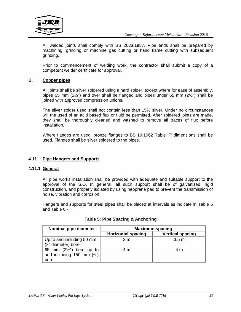
4.11 Pipe Hangers and Supports ........................................................................................33
4.11.1 General ................................................................................................................33
4.11.2 Horizontal Runs ...................................................................................................34
4.11.3 Vertical Runs .......................................................................................................34
4.12 Valves .........................................................................................................................35
4.12.1 General ................................................................................................................35
4.12.2 Gate Valves .........................................................................................................35
4.12.3 Globe Valves .......................................................................................................36
4.12.4 Check Valves .......................................................................................................36
4.12.5 Pressure Relief Valves .........................................................................................36
4.12.6 Butterfly Valves ....................................................................................................36
4.12.7 Manual Balancing Valves ........................................................................................37
4.12.8 Automatic Balancing Valves .................................................................................37
4.12.9 Motorized valves ..................................................................................................37
4.12.10 Triple Duty Valves .................................................................................................38
4.13 Other Pipework Accessories .......................................................................................38
4.13.1 Strainers ..............................................................................................................38
4.13.2 Air Vents (Where Applicable) ...............................................................................38
4.13.3 Pressure Gauges .................................................................................................39
4.13.4 Thermometers .....................................................................................................39
4.13.5 Flexible Joint ........................................................................................................39
4.13.6 Test Plugs for Pressure & Temperature Gauges ..................................................39
4.14 Refrigerant Pipes ........................................................................................................40
4.15 Drain Pipe Insulation ...................................................................................................40
4.16 Refrigeration Pipe Insulation .......................................................................................40
4.17 Underground Piping ....................................................................................................41

Cawangan Kejuruteraan Mekanikal – Revision 2016
Section 3.3 - Water Cooled Package System © Copyright CKM 2016 5
4.18 Pipe Arrangement .......................................................................................................41
5.0 DUCTWORK AND AIR DIFFUSION EQUIPMENT .........................................................41
5.1 Sheet Metal Duct ........................................................................................................41
5.1.1 Flexible Ductwork (Where specified) ....................................................................42
5.1.2 Supports and Hangers .........................................................................................43
5.1.3 Sheet Metal Duct Construction ............................................................................43
5.1.4 Elbows and Turning Vanes ..................................................................................45
5.1.5 Fire Rated Ductwork ............................................................................................45
5.1.6 Fire Resistance Sealant or Non-Combustible Fire Stop Material ..........................45
5.1.7 Access Opening ...................................................................................................46
5.1.8 Cleaning and Protection of Ductwork During and After Installation .......................46
5.1.9 Aluminium Ducts ..................................................................................................46
5.1.10 Insulation of Sheet Metal Ductwork ......................................................................46
5.2 AHU Room Insulation .................................................................................................50
5.3 Duct Silencer ..............................................................................................................50
5.4 Pre-fabricated Duct (Where Applicable) ......................................................................51
5.4.1 Internal Insulation for Pre-fabricated Duct (Open Cell Polyurethane (PU) Foam) .52
5.4.2 Duct Silencer for Pre-fabricated Duct (Where Applicable) ....................................52
5.4.3 Supports and Hangers .........................................................................................53
5.4.4 Duct Connectors to AHU or Fan Housing .............................................................53
5.4.5 Duct Access Opening ..........................................................................................54
5.4.6 Connection Pre-fabricated Duct after Fire Damper ..............................................54
5.5 Registers, Diffusers, Grilles and Dampers ..................................................................55
5.5.1 General ................................................................................................................55
5.5.2 Diffusers and Grilles .............................................................................................55
5.5.3 Registers .............................................................................................................56
5.5.4 Linear Diffusers ....................................................................................................56
5.5.5 Swirl Supply Diffuser ............................................................................................56
5.5.6 Jet Diffuser ..........................................................................................................56
5.5.7 Outside Air Grilles ................................................................................................57
5.5.8 Fire Dampers .......................................................................................................57
5.5.9 Non-Return Dampers ...........................................................................................57
Cawangan Kejuruteraan Mekanikal – Revision 2016
Section 3.3 - Water Cooled Package System © Copyright CKM 2016 6
6.0 VENTILATION AND EXHAUST SYSTEMS ................................................................58
6.1 Exhaust Fan................................................................................................................58
6.2 General Exhaust System ............................................................................................58
6.3 Ducts and Fittings .......................................................................................................58
6.4 Interlocking Devices ....................................................................................................59
6.5 Fan Switches ..............................................................................................................59
7.0 ELECTRIC MOTORS .................................................................................................60
7.1 General .......................................................................................................................60
7.2 Output Rating and Duty ..............................................................................................60
7.3 Motor efficiencies ........................................................................................................60
7.4 Power Factor Requirement .........................................................................................64
8.0 NOISE AND VIBRATION CONTROL ..........................................................................65
8.1 DESCRIPTION OF SYSTEM ......................................................................................65
8.2 DESIGN STANDARDS AND VERIFICATIONS ...........................................................66
8.3 NOISE CONTROL ......................................................................................................66
8.4 VIBRATION CONTROL .............................................................................................70
8.5 PIPING .......................................................................................................................72
8.6 DUCTWORK ...............................................................................................................73
9.0 INDOOR AIR QUALITY (IAQ) REQUIREMENTS........................................................74
9.1 General .......................................................................................................................74
9.2 Design Standard and Verifications ..............................................................................74
9.3 Indoor Air Quality Requirements .................................................................................74
9.3.1 Parameters to Indicate IAQ Status .......................................................................74
9.3.2 Duty to control exposure ......................................................................................74
9.4 Control of Indoor Air Quality ........................................................................................76
9.4.1 Treatment for Air Handling Unit Cooling Coils and Fins .......................................76
9.4.2 Ultraviolet Air Purifier System ..................................................................................76
10.0 ELECTRICAL WORKS ...............................................................................................78
10.1 GENERAL ..................................................................................................................78
10.2 MAIN AIR CONDITIONING SWITCHBOARD .............................................................79
10.2.1 TYPES OF AIR CONDITIONING SWITCHBOARD..............................................79
10.2.2 POWER FACTOR REQUIREMENT FOR MAIN SWITCHBOARD .......................80

Cawangan Kejuruteraan Mekanikal – Revision 2016
Section 3.3 - Water Cooled Package System © Copyright CKM 2016 7
10.2.3 ENCLOSURES ....................................................................................................81
10.2.4 SELF-CONTAINED FLOOR MOUNTED CUBICLE SWITCHBOARDS ...............82
10.2.5 WALL MOUNTED SWITCHBOARDS ..................................................................83
10.3 ASSOCIATED COMPONENTS ..................................................................................84
10.4 AIR CIRCUIT BREAKERS (ACB) ...............................................................................84
10.5 MOULDED CASE CIRCUIT BREAKERS (MCCB) ......................................................86
10.6 MINIATURE CIRCUIT BREAKERS (MCB) .................................................................87
10.7 ISOLATING SWITCHES .............................................................................................87
10.8 CONTACTORS ...........................................................................................................88
10.9 PROTECTION RELAYS .............................................................................................89
10.10 MEASURING INSTRUMENT AND ACCESSORIES................................................90
10.10.1 MEASURING INSTRUMENT ...........................................................................90
10.11 CURRENT TRANSFORMERS ................................................................................92
10.12 SURGE PROTECTION DEVICE .............................................................................92
10.13 SYSTEM OF WIRING .............................................................................................95
10.14 TYPES OF CABLE ..................................................................................................96
10.14.1 PVC Insulated PVC Sheathed Cable .....................................................................96
10.14.2 PVC Insulated Cable .............................................................................................96
10.14.3 XLPE/PVC Cable ..................................................................................................96
10.14.4 Armoured Cable ....................................................................................................96
10.14.5 Mineral-Insulated Cables .......................................................................................97
10.15 WIRING IN CONDUIT/TRUNKING (SURFACE OR CONCEALED) .............................99
10.16 METALLIC CONDUITS ...........................................................................................99
10.17 CABLE TRUNKING ............................................................................................... 100
10.18 CABLE TRAYS...................................................................................................... 101
10.19 CABLE LADDER ................................................................................................... 102
10.20 MOUNTING HEIGHTS .......................................................................................... 103
10.21 EARTHING ............................................................................................................ 103
10.22 LABELLING ........................................................................................................... 104
10.23 STARTERS ........................................................................................................... 104
11.0 CLEANING, PAINTING AND IDENTIFICATION ....................................................... 105
11.1 General ..................................................................................................................... 105

Cawangan Kejuruteraan Mekanikal – Revision 2016
Section 3.3 - Water Cooled Package System © Copyright CKM 2016 8
11.2 Cleaning ................................................................................................................... 105
11.3 Metal Surfaces .......................................................................................................... 105
11.4 Insulated Surfaces .................................................................................................... 105
11.5 Painting of Pipelines ................................................................................................. 105
11.6 Colors ....................................................................................................................... 106
11.7 Valve Tags ................................................................................................................ 106
11.8 Name Plates ............................................................................................................. 106
11.9 Sample of Material for Submission and Approval ...................................................... 106

Cawangan Kejuruteraan Mekanikal – Revision 2016
Section 3.3 - Water Cooled Package System © Copyright CKM 2016 9
List of Table Table 1 : ACMV System Equipment, Electrically Driven: Standard Rating Temperatures-Cooling
(MS1525:2014) ...........................................................................................................10
Table 2 : Unitary Air Conditioners, Electrically Driven: Minimum COP – Cooling .......................11
Table 3 : MERV RATING CHART .............................................................................................14
Table 4: Condenser Water Condition Specification ...................................................................23
Table 5: Pipe Spacing & Anchoring ...........................................................................................33
Table 6: Pipe Anchoring ............................................................................................................34
Table 7: Duct Construction Table (using Steel Sheet Metal) .....................................................43
Table 8: Duct Hanger Rod and Support/Bracket Size (using Pre-Fabricated Duct) ...................53
Table 9: Selection of Efficiency Class .......................................................................................60
Table 10: Efficiency Class Definition for 2-Pole Motors (MS 1525:2014) ...................................61
Table 11: Efficiency Class Definition for 4-Pole Motors .............................................................62
Table 12: Efficiency Class Definition for 6-Pole Motors .............................................................63
Table 13: Recommended Noise Criteria (NC) – Room Criteria (RC) and Maximum Sound
Pressure Level (Lp) for Different Indoor Activity. .......................................................68
Table 14: Recommended Noise Criteria (NC) – Room Criteria (RC) and Maximum Sound
Pressure Level (Lp) for Different Indoor Activity (cont’). ............................................69
Table 15: Vibration Isolators Schedule ......................................................................................70
Table 16: Absorption Coefficient ...............................................................................................73
Table 17: Acceptable Range for Specific Physical Parameters .................................................75
Table 18: Acceptable Limits of Indoor Air Contaminants ...........................................................75
Table 19: Type Testing for Switchboard As Per Categorization .................................................80
Table 20: IEC Utilization Categories ..........................................................................................88
Table 21 : Parameters Accuracy ...............................................................................................91
Table 22: Surge Protecting Devices ..........................................................................................94
Table 23 : Cable Trunking ....................................................................................................... 100
Table 24 : Mounting Heights ................................................................................................... 103
Table 25: Starters ................................................................................................................... 104

Cawangan Kejuruteraan Mekanikal – Revision 2016
Section 3.3 - Water Cooled Package System © Copyright CKM 2016 10
SECTION 3.3 WATER COOLED PACKAGE SYSTEM 1.0 WATER COOLED PACKAGE SYSTEM
1.1 General The water-cooled package air-conditioning unit(s) shall be of the self-contained type. The unit/s shall contain refrigerant circuits, each consisting of hermetic compressor(s) and a direct expansion cooling coil complete with expansion valves and solenoid valve controls. The unit shall be complete with water-cooled condenser(s), fan(s) and drives and air-filters, all enclosed in an insulated steel cabinet.
The water-cooled package/split ducted system for standard rating temperatures and minimum coefficient of performance (COP) shall be accordance with Table 1 and Table 2.
Table 1 : ACMV System Equipment, Electrically Driven: Standard Rating
Temperatures-Cooling (MS1525:2014)
Item Air-cooled Water-cooled (water-source)
Dry-bulb Wet-bulb Inlet Outlet
Room air entering equipment (oC) Condenser ambient (air-cooled) (oC) Refrigerant-water heat exchanger (oC)
27.0
35.0 -
19.0
24.0 -
- -
30.0
- -
35.0
NOTES: 1. Data in this table apply to the following types of equipment:
a) central Air Conditioners: Air, Evaporatively and Water Cooled, ISO 13253; and b) commercial/Industrial Unitary Air-Conditioning Equipment, MS ISO 5151, ISO 13253.
2. Standard ratings are also based on other standard rating conditions such as, but not limited to,
electrical conditions; cooling air quantity; requirements for separated (split) assemblies; and minimum external flow resistance, as provided in the applicable standards.

Cawangan Kejuruteraan Mekanikal – Revision 2016
Section 3.3 - Water Cooled Package System © Copyright CKM 2016 11
Table 2 : Unitary Air Conditioners, Electrically Driven: Minimum COP – Cooling
(MS 1525:2014)
Equipment Size Sub-category Minimum COP
Non-Inverter type Inverter type 1
Air conditioners: Air cooled with condenser
< 19 kWr
Single Split/Package 2.8 3.0
Multi-split 2.8 3.2
> 19 kWr and < 35 kWr
Split or package 2.8 3.5
> 35 kWr
Split or package 2.7 2.9
Air conditioners: Water and evaporatively cooled
< 19 kWr Split or package 3.6 4.0
> 19 kWr and < 35 kWr
Split or package 3.7 4.4
> 35 kWr
Split or package 3.8 4.4
NOTE: 1. The COP for the inverter unit is the weighted value, which is calculated based upon the following equation:
COPweighted = [COP100% x 0.40] + [COP50% x 0.60]

Cawangan Kejuruteraan Mekanikal – Revision 2016
Section 3.3 - Water Cooled Package System © Copyright CKM 2016 12
1.2 Compressor The compressor/s shall be assembled complete with all necessary accessories on a steel base with vibration isolators. e.g spring-mounted type. Individual water cooled Direct Expansion (DX) units greater than 35 kWr (reciprocating compressor) or 65 kWr (scroll compressor) should consist of either multi compressors or single compressor with step/variable unloaders. Compressors shall be equipped with oil failure control, dual pressure control, safety valves, suction and discharge valves, crankcase heaters, suction gas strainer, oil sight glass and other accessories if necessary. The compressor and motor shall be run not be more than 2900 rpm and the compressor cooling capacity rating and power rating shall be based on approved standard. The motor shall be of the AC Induction type specifically designed for operation on 400 volts (+10%,-6%), 3 phase, 50 cycles or 230 volts, single phase electric supplies, where ever applicable.
1.3 Evaporator Cooling Coil
The cooling coils of each unit shall be extended surface direct expansion coils of approved manufacture, constructed from copper tube with aluminium fins or otherwise stated in Schedule of Design Requirement and having not less than 8 fins per 25 mm. Bonding of the fins to the tube shall be by mechanical means to ensure a positive lasting bond. The coils shall be fitted with headers and a suitable distribution network designed to produce uniform distribution of refrigerant over the face of the coils. Each header shall be fed through a thermal expansion valve and solenoid valve.
1.4 Refrigerant
Refrigerant shall be R410a or other approved environment-friendly and chlorine-free refrigerant as per schedule of design requirement.
1.5 Water-Cooled Refrigerant Condensers
The refrigerant condenser shall be of the multi-pass shell and tube type having replaceable seamless copper tube with integral aluminium fins and removable cast iron water headers. The refrigerant condenser shall be equipped with a pressure relief device, a liquid line shut-off valve and an angle valve with connection for a water regulating valve. The condenser shall be constructed and tested in accordance with the A.S.M.E. Code for Unfired Pressure Vessels, and shall be supplied complete with mounting stands, mounting brackets, vibration isolators and all necessary accessories.

Cawangan Kejuruteraan Mekanikal – Revision 2016
Section 3.3 - Water Cooled Package System © Copyright CKM 2016 13
1.6 Liquid Receiver The liquid receiver shall be welded steel construction and shall be constructed and tested in accordance with the A.S.M.E. Code for Unfired Pressure Vessels, and shall be supplied complete with mounting stands, mounting brackets, vibration isolators and all necessary accessories. The liquid receiver shall have ample storage capacity for a complete pump down of the refrigerant system to which it is connected.
1.7 Centrifugal Fan The fan/s of each Package unit shall be multi-blade centrifugal type. All fans shall statically and dynamically balanced and tested. The fan housings shall be constructed with die-formed streamlined inlets and side sheets. The fans shall be made of light aluminium alloy or other approved materials. A method of mounting giving full belt adjustment shall be incorporated and belt guards provided. A suitable pitch pulley shall be provided on the driving motor. The maximum outlet velocity of the fans shall not exceed 550mpm (1800 fpm). The fans shall be either forward curve or backward inclined depending on the sizes.
1.8 Air Filters
1.8.1 Filter Section The filter section shall be supplied with the same casing construction as the air handling equipment. The type of filters to be housed shall be of the type and efficiency indicated in the drawings or stated elsewhere in this specification. High velocity filter section shall be capable of receiving filters of standard sizes. The filters shall be arranged in banks in sufficient numbers to operate at the correct manufacturer's rating, and shall be supported in a suitable aluminium holding frame. The filter housing design shall be such that it allows speedy removal and replacement of the filter media. Each air filter shall be of a readily available standard size and have a thickness of 50 mm. The filter design shall be such that it allows speedy removal and replacement of the filter media.

Cawangan Kejuruteraan Mekanikal – Revision 2016
Section 3.3 - Water Cooled Package System © Copyright CKM 2016 14
The filter media shall have the following characteristic: - Maximum face velocity : 2.8 m/s (550 fpm) Minimum filtration efficiency : MERV 7 ASHRAE Standard 52.2-2007
Table 3 : MERV RATING CHART
Efficiency Reporting Dust Spot Typical Controlled Typical Applications and Value Efficiency Arrestance Contaminant Limitations Typical Air Filter/Cleaner Type
20 >99.999% eff. On .10-.20 pm
n/a n/a < 0.30 pm particle size Cleanrooms Particles
19
n/a n/a Virus (unattached) Radioactive Materials Particles
18 n/a n/a Carbon Dust Pharmaceutical Man. Particulates
17 n/a n/a All Combustion smoke Carcinogenetic Materials >99.97% eff. On .30 pm Particles
16 n/a n/a .30-1.0 pm Particle Size General Surgery Bag Filter- Nonsupported 15 >95% n/a All Bacteria Hospital Inpatient Care microfine fiberglass or
14 synthetic media, 12-36 in. deep, 6-
90-95% >98% Most Tobacco Smoke Smoking Lounges 12 pockets
Box Filter- Rigid Style Cartridge
13 Filters 6 to 12" deep m ay use
89-90% >98% Proplet Nuceli (Sneeze) Superior Commercial Buildings lofted or paper media.
12 70-75% >95% 1.0-3.0 pm Particle Size Superior Residential Bag Filter- Nonsupported
Legionella microfine fiberglass or
11 synthetic media, 12-36 in. deep, 6-
60-65% >95% Humidifier Dust Better Commercial Buildings 12 pockets
Lead Dust
Box Filter- Rigid Style Cartridge
10 Filters 6 to 12" deep m ay use
50-55% >95% Milled Flour lofted or paper media.
Auto Emissions Hospital Laboratories
9 40-45% >90% Welding Fumes
8 Pleated Filters- Disposable,
30-35% >90% 3.0-10.0 pm Particle Size Commercial Buildings extended surface area, thick with
cotton-polyester blend media,
Mold Spores cardboard frame
7 25-30% >90% Hair Spray Better Residential
Cartridge Filters- Graded density
viscous coated cube or pocket
Fabric Protector filters, synthetic media
6 <20% 85-90% Dusting Aids Industrial Workplace
Throwaway- Disposable
Cement Dust synthetic panel filter.
5 <20% 80-85% Pudding Mix Paint Booth Inlet
4 Throwaway- Disposable
<20% 75-80% >10.0 pm Particle Size Minimal Filtration fiberglass or synthetic panel filter.
Pollen
3 <20% 70-75% Dust Mites Residential Washable- Aluminum Mesh
Sanding Dust
2 <20% 65-70% Spray Paint Dust
Electrostatic- Self charging
Textile Fibers Window A/C Units woven panel filter.
1 <20% <65% Carpet Fibers

Cawangan Kejuruteraan Mekanikal – Revision 2016
Section 3.3 - Water Cooled Package System © Copyright CKM 2016 15
1.8.2 Air filter material (Where specified)
Selection of air filter material shall be as per Schedule of Design Requirements.
i) Air filter Synthetic/Polyester media shall be 100% non-woven polyester fibers, bonded together with a flame retarding agent which forms a high loft of resilient fibers. Available in either single or multi-ply grade and is dry or treated with a non-toxic, non-migratory, odourless adhesive that is incorporated into the media. Each grade of synthetic media is specifically engineered for a variety of dust loading applications.
ii) Air filter fiberglass media consists of a continuous filament fiberglass of graduated density to ensure depth loading. The air leaving side of the media incorporates a skin backing which supports the media and creates a final filtration stage. All fiberglass media shall be treated with a non-toxic, non-flammable and odourless adhesive.
1.9 Primary Filters Each filter shall be of a readily available standard size and have a thickness of 50 mm. The filter design shall be such that it allows speedy removal and replacement of the filter media. The primary filter shall be as first stage in the Air Handling Equipment. The filters shall be of sufficient numbers and capacity to clean the specified air quantity. The average Synthetic Dust Weight Arrestance according to ASHRAE Standard 52-76 shall be 85%, and Dust Spot Efficiency (Atmospheric) shall be 30%. Initial resistance shall be less than 50 Pa (0.2 inch water). The filter frame shall consist of an outer section able to be permanently mounted and a quick release removable gate section from which the filters only can be removed for changeover. The frame shall be fabricated from 1.25 mm thick zinc anneal steel, phosphated after fabrication prime etched and enamel paint finished. Heavy aluminium frames may also be used. The filters shall be supported on both sides by 2.6 mm (12 S.W.G) mesh at intervals of not more than 100 mm apart in each direction. An additional set of filter shall be supplied for number of filter supplied. 1.10 Secondary Filters (Where Applicable) Secondary filter shall be installed in all supply air systems as indicated in the drawings. The filter holding frame shall be made of corrosion resistance treated galvanized steel or aluminium frame constructed in a rigid manner. Filters shall be held in place by an approved proprietary factory made housing which ensures complete air-tight seal between holding frame and the housing. A positive locking mechanism shall be supplied. The filters housing shall be

Cawangan Kejuruteraan Mekanikal – Revision 2016
Section 3.3 - Water Cooled Package System © Copyright CKM 2016 16
constructed in such a manner that filters can be removed easily for replacement and servicing purposes. The second stage filter shall have an efficiency of not less than 90-95% to ASHRAE Std. 52-76 Dust Spot Test Method on atmospheric dust. The clean filter initial static shall not be more than 150 Pa (0.6 inch water). An additional set of filter shall be supplied for number of filter supplied. Secondary filter shall be used only for AHUs specified in Schedule of Design Requirement.
1.11 Electronic Air Cleaner (EAC) (Where Specified)
1.11.1 General The Electronic Air Cleaner system is a two stage electrostatic precipitation electrically charges air particles to create an effective method for capturing airborne contaminants. The EAC is mounted to AHU/FCU. The charging stage is an initial stage where most large particles are caught on the pre-filter screen. Smaller particles flow through the screen to the first section of the air cleaner cell, where they pass through a series of high-voltage ionizing wires and become electrically charge. The particles charged through the cell to the collecting section where the collector stage starts. The charged particles are attracted like magnets to a series of oppositely charged collector plates. Electronically filtered air is circulated back into the building environment.
1.11.2 Approvals / Code Requirements The EAC shall be Underwriter Laboratories (UL) Listed, Canadian Standards Association certified (UL 867). The EAC shall also be EMC (Electromagnetic compatibility) certified and shall be installed as a complete unit as approved by UL and the manufacturer. Ozone level of EACs provided shall be within the acceptable limit set by ASHRAE, FDA and UL. The efficiency rating of the equipment shall be determined by the American Society of Heating, Refrigeration, and Air-Conditioning Engineers (ASHRAE) Standards 52-76, Atmospheric Dust Spot Test. Tenderers shall provide certificate and test report on the above requirement upon request.
1.11.3 Safety Provisions The EAC shall have a microprocessor-controlled switching high voltage power supply for precise control of output voltage and current. The output shall conform to the non-lethal

Cawangan Kejuruteraan Mekanikal – Revision 2016
Section 3.3 - Water Cooled Package System © Copyright CKM 2016 17
circuit requirement of the National Electric Code and UL Standard 867. The high voltage output shall not exceed 5.0 mA under any conditions. There shall not have any high frequency emission from the proposed equipment. Each EAC chassis shall have their automatic interlock switch, which disconnects power and discharges the cell when the door is opened. In addition, the EAC shall be capable of interlocking to disconnecting the power to each individual EAC unit when the AHU / FCU fan is not running. A high voltage test button shall be provided for each individual unit to indicate the presence of high voltage on the electronic cells. All high voltage output connection from the power supply to the cells must be in high-tension cable, approved by UL, CSA or in compliance to local CP code. For safety considerations, all power supplies shall be built into the EAC and shall not be remotely mounted.
1.11.4 Performance / Reliability Requirements The average capacity of the EAC shall be 1000cfm (1700 cmh) for the single cell unit and 2,000 cfm (3400cmh) for the double cells unit. The atmospheric dust spot efficiency (ASHRAE 52-76) of the EAC shall be at least 70% (at 2,000 cfm) and up to 95% (at 800 cfm). The proposed equipment shall be capable of capturing sub-micron particulates/contaminants down to 0.01 microns. All tenderers shall submit test results of filtration efficiency by Air Filter Testing Laboratories for efficiency verification. The solid state power supply shall provide sufficient voltage to the ionizer and collector section. The voltage to the ionizer shall be at least 8,150V D.C. to create an intense electrostatic field to allow maximum transfer of electrical charge from the ionizing wires to the air particles. The voltage to the collector shall be at a maximum of 4,075V d.c. The simplified single voltage and / or ferroresonant type of power supply shall not be acceptable. The tenderers shall provide an on-site test on each power supply pack to ensure the output DC voltage is sufficient with a high voltage test probe. Each 2,000 cfm of filtration shall be generously served with two cells of at least 71 collector plates per cells respectively. The distance between collector plates shall be 4/32 inch or less to ensure an intense electrical field to maximize particle captures by the collector plates. There shall not have any necessity for replacement ‘back filters’. The entire filtration system shall be washable and reusable, without the need for replacements. The average pressure differential drop across the entire filtration system shall not exceed 0.25” w.c. (0.06 kPa) at 2,000 cfm (56,634liter/min)and 2.5 m/s airflow

Cawangan Kejuruteraan Mekanikal – Revision 2016
Section 3.3 - Water Cooled Package System © Copyright CKM 2016 18
Each filter cell shall not have a carrying weight of more than 10 lb. (4.5 kg) for easy handling and transportation. The ionizing wires and collector plates shall be integrated within one pack. It shall be washable for repeated use. The EAC shall be completed with galvanized cabinet to protect against rust, heavy duty commercially used electronic cells, solid state power supply, protective screen and pre-filter. A washable aluminium mesh pre-filter shall be provided at the inlet to trap all larger sized particles. The EAC shall have built in Non-Thermal Plasma Micro Oxidation system (NTP) for removal of odour and gaseous contaminants. Equipment dimensions shall be suitable to allow easy installation within constrained spaces of the AHU / FCU.
1.11.5 Installation
All works shall be carried out in a safe and proper manner with good workmanship. The Contractor shall provide close supervision for the work carried out by his workmen . The EACs shall be installed at the return of the AHU, just before the cooling coil. In order to have proper air-flow through the electronic cells and eliminating any air by-pass, the EAC shall be ‘enclosed’ with sheet metal frames attached to the AHU. The Contractor shall test and commission all of the EACs. All cables used to connect the EACs to the incoming power shall be PVC insulated 450/750V grade conforming to the MS IEC 60364-5-52.
1.12 Package Unit Cabinets
1.12.1 Single Skin The packaged unit cabinet shall be constructed from heavy gauge galvanized steel reinforced and braced with steel angle framework for maximum rigidity. Each unit shall have predrilled flanges with identical hole locations to permit easy assembly of adjoining sections or modules. Each unit shall be adequately insulated for tropical conditions and the insulation shall be at less PU foam of 25 mm thickness with a minimum density of 40kg/m3 and thermal conductivity K-factor of 0.02W/m.K. or approved equivalent sprayed on the inside with an approved protective vinyl coating.

Cawangan Kejuruteraan Mekanikal – Revision 2016
Section 3.3 - Water Cooled Package System © Copyright CKM 2016 19
1.12.2 Double Skin The casing shall have a perimeter frame, with a wholly modular system based on standardised panels and reinforced vertical sections. The casing panels shall be of heavy gauged galvanized sheet steel. These panels shall be constructed such that they shall comprise of two layers of galvanized sheet steel sandwiching the polyurethane insulation in between. The insulation shall be of minimum 50 mm thickness and density of 40 kg/m3 and thermal conductivity not exceeding 0.02 W/m.K. The external clip method shall hold the double skin PU insulation panels and it shall allow easy access during maintenance, besides ensuring good air tightness. The panels shall create a thermal barrier/bridging between the internal and external surfaces of Class 2 as stipulated in EN 1886. The leakage level shall conform to Class B as stipulated in EN 1886. The floor panels shall have double skinned construction to allow access without damaging the insulation. Cooling coils shall be placed in a double skinned casing section. The condensate drain pan shall be furnished with threaded pipe connection. Filters, heaters (if any), fan and cooling coils shall be placed in a double skinned casing section. The cooling coil and condensate drain pan shall be assembly mounted on slides such that the cooling coil and condensate pan can be wholly removable to facilitate easy maintenance. Moisture eliminators shall be provided when the coil face velocity exceeds 3 m/s. The eliminator shall have a minimum of 3 air flow direction changes. For chilled water ceiling suspended unit, the insulation shall be of minimum 25 mm thickness and density of 40 kg/m3 and thermal conductivity of not exceeding 0.02 W/m.K Double skinned units shall be used only for packaged unit cabinet specified in Schedule of Design Requirement.
2.0 COOLING TOWER
2.1 General
The cooling towers shall either be factory assembled in single fan modules or field erected towers utilizing fully factory components. In addition, the cooling towers shall be of reputable brands with manufacturer's guaranteed capacity performance and selection of type of cooling tower shall be as per Schedule of Design Requirements. All model of cooling tower shall be CTI Certified and perform thermally as per CTI Standard 201. Operation condition of cooling tower shall produce maximum noise level limit not more than 75 dBA, measured 1 meter away from external wall at site.

Cawangan Kejuruteraan Mekanikal – Revision 2016
Section 3.3 - Water Cooled Package System © Copyright CKM 2016 20
a) Induced Draft Cross Flow Type
Each cooling tower shall be of low noise induced draft, double air entry, cross flow type with vertical air discharge and shall be capable of cooling the specified quantities of condenser water under the conditions as listed in the Schedule of Design Requirement.
b) Induced Draft Counter flow Type
Each cooling tower shall be of low noise induced draft constructed from reinforced polyester of good quality and shall be capable of cooling the specified quantities of condenser water under the conditions as listed in the Schedule of Design Requirement. The cooling tower shall be installed complete with steel skid base on concrete plinths as per Table 14: Vibration Isolators Schedule.
2.2 Performance
The selection of the cooling tower shall be based on inlet water temperature of 36.11°C (97°F), outlet water temperature of 30.55ºC (87ºF) and at a maximum air wet bulb temperature of 27.2ºC (81ºF) as per MS1525:2014.
2.3 Construction
a) Induced Draft Cross Flow Type
Casing and Louvers The materials for these shall be plastic or hot dip galvanized sheet steel.
Eliminators Drift eliminators shall be plastics (PVC) and shall have a minimum of two distinct changes in air direction and limit drift loss to not more than 0.001 to 0.005% water circulation rates. Distribution system
Distribution weirs and metering nozzles shall be provided to ensure even distribution of water. Flow control and shut - off valves of each discharge end of the pipe shall be also provided.

Cawangan Kejuruteraan Mekanikal – Revision 2016
Section 3.3 - Water Cooled Package System © Copyright CKM 2016 21
Basins Unless specified otherwise, the collection basin shall either be FRP or hot-dip galvanized steel and shall be self-cleaning with adequate capacity to hold the circulating condenser water so that there shall be no excessive overflow when pump is stopped. The basin shall be complete with quick fill inlet and valve, make-up water valve operated by large diameter plastic float. Infill The infill shall be of wave-formed sheets of self-extinguishing PVC. The infill shall be permanently positioned such that it allows for expansion and contraction without cracking, warping or sagging.
b) Induced Draft Counterflow Type
Infill The infill shall be of rigid PVC of either U-packing honeycomb type or having high heat transfer efficiency. The infill shall be closely packed and evenly distributed and supported by PVC mesh.
Drift eliminators PVC or aluminium specially shaped baffle plates shall be attached to the distributing pipes to prevent excessive carry-over of moisture. Wind guard Vertical division plates at lower inside of the tower shall be provided to keep wind from blowing out through its open sides. Hardware All hardware used in the construction shall be supplied by the cooling tower manufacturer. In general all bolts, nuts and fasteners shall be non-ferrous materials to avoid corrosion.
2.4 Fan and Motor
The fan shall be multi bladed with fixed or adjustable pitch as specified in the Schedule of Design Requirement. The fan blades shall be heavy duty cast aluminium and housed within a fan cylinder design for streamline air entry.

Cawangan Kejuruteraan Mekanikal – Revision 2016
Section 3.3 - Water Cooled Package System © Copyright CKM 2016 22
Fan motor shall be totally enclosed air cooled suitable for operation on 400 volts (+10%,-6%), 3 phase, 50 Hz supply. Motors shall be furnished with special moisture protection on windings, shafts and bearings with minimum IP 65. The motor speed shall not be more than 1450 rpm. All steel components or structures used for installation of the mechanical equipment of the cooling tower shall be hot-dipped galvanized steel.
2.5 Make Up Water Tank
All make-up water tanks shall be of a minimum 5 mm thickness hot-dip galvanized pressed steel treated with anti- rust coating. The size of the make-up water tank shall be as in the Schedule of Design Requirement / tender drawing. The water tank shall be mounted complete with steel skid base on concrete plinths. The inspection cover shall be constructed from minimum 3.3 mm (10 SWG) thick galvanized steel sheet. The tank shall be supplied complete with: 1. Level indicators of the float type. 2. Mechanical level indicator complete with float, guides, stainless steel cable,
pulleys and a direct reading scale suitably placed adjacent to the inspection cover.
3. External and internal access ladders shall be of stainless steel material 4. Vent pipe complete with mosquito net. 5. Scour pipe complete with drain valve. 6. Inlet pipe complete with ball valve and gate valve.
2.6 Cooling Tower Water Treatment
The water treatment system shall be a complete package incorporating proportional metering equipment, feed tanks, mixing tanks and other accessories. The system shall be suitable for continuous automatic water treatment for trouble free operation of the Air- Conditioning system. The system shall be installed and commissioned strictly in accordance to the manufacturer's instruction. The chemicals used must be readily available locally and must be approved by the Ministry of Health/Ministry of Environment for discharge into open drains or atmosphere. The chemicals used shall be able to treat against legionella, algae, corrosion and scalling. Sufficient chemicals shall be supplied for one (1) year continuous normal operation of the cooling tower. A test kit for determining water conditions shall also be provided.

Cawangan Kejuruteraan Mekanikal – Revision 2016
Section 3.3 - Water Cooled Package System © Copyright CKM 2016 23
2.6.1 Non-chemical Water Treatment (where specified)
The water treatment system shall be a complete package incorporating proportional metering equipment, precipitate centrifugal separator and other accessories. The system shall be suitable for continuous automatic water treatment for trouble free operation of the Air Conditioning system. The system shall be installed and commissioned strictly in accordance to the manufacturer's instruction. The solutions and equipment used shall be able to treat against biological microorganisms (algae, legionella etc), corrosion and scalling. A water test shall be done before considering a non-chemical water treatment due to system limitation:
a) Will not work with very soft or distilled water b) Less effective when the water has a high chloride or silicate content.
Selection of water treatment shall be as per Schedule of Design Requirement.
2.6.2 Condenser Water Treatment The treatment programmed shall achieve the following chemical and micro-organism limits in the water:
Table 4: Condenser Water Condition Specification One year’s supply of at least two (2) types of non-chromate chemicals shall be provided to control scale formation and corrosion inhibition. One year’s supply of at least two (2) types of liquid biocides shall also be provided for control of micro-biological growth including Legionella bacteria. All chemical shall be supplied in containers that are
Conditions Specifications
Total hardness 0-1000 ppm Max. Alkalinity 100-300 ppm
Chloride Dependent on no. of cycles with min. 6 cycles of concentration
pH 7.5 – 8.5
Total Dissolved Solids 0-800 ppm General Bacteria Count (inclusive of Legionella) 1 x 10³ counts/ml
Corrosion Rate Mild Steel coupon <5 mpv Cooper coupon <0.3 mpv

Cawangan Kejuruteraan Mekanikal – Revision 2016
Section 3.3 - Water Cooled Package System © Copyright CKM 2016 24
applicable for pumping from containers to reticulation system and shall conform to all applicable codes.
2.6.3 Surveillance Program The water treatment specialist shall provide one year’s surveillance consulting program which shall include training of Employer’s maintenance personnel in operation of chemical treatment system, and a continuing program of surveillance. The consulting surveillance inspections check-analysis procedures shall be on a monthly frequency. The field surveillance technician shall review field test procedures and water control reports, inspect chemical feeding equipment, and recommend any modifications in program necessary to improve controlled environment, verification of procedures. Each field surveillance inspection and check-analysis procedure shall include the following: a) Corrosion monitoring of test coupons analyzed by laboratory. b) Field water test report c) Log sheets d) Name and qualifications of the person conducting the inspection.
2.7 Service Ladder and Platform
For cooling towers which stands at more than 1.5m high shall be equipped with a galvanized steel or aluminium service ladder. Service platform shall be provided for inspection/maintenance purposes where more than one cooling tower is installed. The service platform shall be interconnected in adjacent to the arrangement.
3.0 PUMPING EQUIPMENT (CONDENSER WATER)
3.1 General
The type of pumps shall be as specified in the Schedule of Design Requirements. The pump shall be of the horizontally split casing, centrifugal double volute type. The suction and discharge nozzles shall be in the lower half of the casing to permit removal of the shaft impeller assembly without disturbing the suction and discharge piping. For pump sets below 15 kW (20 hp), centrifugal, end-suction type of pump may be offered provided the pump has special provision such as spacer for coupling to enable service and maintenance to pump without having to disconnect the suction/discharge piping. All pumps selected shall be designed for not more than 1500 rpm operation and shall have the required pumping rate and head. The performance of the pump selected shall be indicated on manufacturer's supplied performance curves for verification.

Cawangan Kejuruteraan Mekanikal – Revision 2016
Section 3.3 - Water Cooled Package System © Copyright CKM 2016 25
The following information shall be submitted together with the tender: Head capacity, efficiency, BHP, NPSH, Pumps and System Characteristic Curves. Literature, catalogue and drawings describing the unit offered.
3.2 Casing
The casing material shall be of close-grained cast iron or cast steel. The bearing bracket shall be cast integrally with the lower half casing. The upper half casing shall be fitted with lugs or eye bolts. The casing shall be provided with all necessary vents, drain plugs and gauge connection.
3.3 Impeller
The material of the impeller shall be of the bronze, machined on the outside and hand finished on the inside. The impeller shall be dynamically balanced and mounted on the pump shaft with a key.
3.4 Shaft and Sleeve
The pump shaft shall be heat treated bright stainless steel, accurately machined and ground over its entire length. The shaft shall be protected from wear and erosion in the pumps and stuffing box by removable bronze sleeves. These sleeves are to be keyed to the shaft and held in place by separate external bronze shaft nuts. The sleeves shall be provided with a positive means of preventing leakage between the shaft and sleeves, such as 'O' rings or soft sleeve packing. The shaft shall be tapered at the coupling end for easy removal of the pump half coupling.
3.5 Wearing Rings
The casing shall be fitted with bronze wearing rings of the nozzle type, which will help guide the water efficiently to the impeller eye. The casing ring shall be fitted against a shoulder in the top and bottom half of the casing and provided with positive means or preventing rotation. The impeller shall also be fitted with removable bronze wearing rings.

Cawangan Kejuruteraan Mekanikal – Revision 2016
Section 3.3 - Water Cooled Package System © Copyright CKM 2016 26
3.6 Bearings
The pump bearings shall be of the heavy duty anti friction ball or spherical roller type, arranged for grease lubrication. Removable bearing housing shall be bolted and dowelled to bearing brackets that are cast integral with the pump lower half casing. Bearing housing shall be provided with a drain plug on the opposite side from the grease cup to facilitate cleaning and lubrication of the bearing. The inboard and outboard bearings of the pump shall be of the same size and type.
3.7 Mechanical Seal
The pump seal shall be integral with the casing and shall be of the mechanical seal type. The mechanical seal material shall be of either silicon carbide, carbon or ceramic type and suitable for fluid media operation.
3.8 Flexible Coupling
The pump shall be directly connected to its driver by means of a gear type flexible coupling. The pump half coupling shall be mounted on the shaft by a taper feed and held on by a coupling nut to permit easy removal. An approved protective guard shall be provided.
3.9 Base Plates
Pump and driver shall be mounted on a fabricated steel base plate. The base plate shall be provided with a grout hole of adequate size.
3.10 Special Tools
All special tools for the maintenance and operation of the pumps shall be furnished.
4.0 PIPEWORKS
4.1 General The work involved includes but shall not be limited to the supply and installation of all necessary pipe, valves, fittings, anchors, supports, brackets, insulation etc. unless specifically excluded elsewhere in this Specification.

Cawangan Kejuruteraan Mekanikal – Revision 2016
Section 3.3 - Water Cooled Package System © Copyright CKM 2016 27
The pipe work shall be carried out by competent person in accordance with the best engineering practice to conform the diagrams and layouts shown in the Tender Drawings.
4.2 Regulations
All pipelines shall be constructed in accordance with the relevant Regulations and Standard.
4.3 General Piping Instructions
In general, piping has been shown diagrammatically on the drawings. Care shall be taken to install this piping exactly as shown. Should field condition prevent this installation exactly as shown, this section of the work shall be decided by Superintending Officer (S.O). Where piping is to be furred in or concealed or buried under ground, the Contractor is to coordinate all the works to maintain lines and levels. Unless otherwise noted, all branches shall be taken off the main at a 45º angle above the main when feeding up, 45º angle below the mains when feeding down. Before horizontal run outs are taken off, such vertical air bottles shall be fitted using equal or reducing tee at the high point of the risers. Horizontal runs of pipes shall, where practicable, be graded down in the direction of flow and drain at low points. All straight vertical run of pipe more than 30 meters length shall have dirt pockets formed from equal tee and plugs at the low point of the risers. All piping must be so constructed that it will be free from contraction and expansion, so that it will not damage any other work or affect injury to itself. Under no circumstances are sizes to be reduced from those shown on the drawing or specified. Unless otherwise stated all valves, strainers, bypass lines, etc., shall be the same size as the line and shall not be sized to match control valves sizes. As soon as lines have been installed, all openings shall be capped or plugged to prevent the entrance of the materials that would obstruct the pipe. Caps and plugs shall be left in place until removal is necessary for completion of installation. All piping shall be flushed or blown clean and strainers or line pockets cleared of all foreign materials before putting the lines into service. All piping shall be thoroughly cleaned, free from scale by wire brushing and shall be left in proper condition for painting or insulating. In all exposed piping installed, there shall be clearance of approximately 50 mm left between the outlet of the pipe or insulation and the nearest wall, ceiling or equipment

Cawangan Kejuruteraan Mekanikal – Revision 2016
Section 3.3 - Water Cooled Package System © Copyright CKM 2016 28
surface. Pipes shall be run at a minimum distance apart to enable them to be individually insulated and painted. Combined insulation of two or more pipes will not be approved.
4.4 Type of Pipes
The type of pipes to be supplied shall conform to the following specification:-
4.4.1 Condenser water pipes
All condenser water pipes shall be heavy gauge galvanized steel Class C pipes to BS EN 10255:2004 suitable for the pressure rating. Detail of underground pipe specification shall be as per Clause 4.17: Underground Pipes.
4.4.2 Drain pipes All drain pipes shall be of heavy gauge galvanized steel Class C to BS EN 10255:2004 for all sizes.
4.4.3 Fill pipes
Fill pipe installed to the chilled water or condenser water circuits shall be of approved size and shall be of the same material as the pipe to which it connects.
4.5 Galvanized Coating for Steel Pipes
All galvanized coating for steel pipes shall conform to BS EN ISO 1461:2009.
4.6 Pipe Flanges
In general, flanges shall be provided at each piping connection of the equipment, valves or strainer. Unless otherwise specifically mentioned, the flanges provided shall be of the weld neck type. Mating faces of the flanges for each connection must be compatible and with bolt holes in perfect alignment. The mating of a raised face flanged to a flat faced flange will not be permitted.
4.7 Pipe Sleeves
Pipe sleeves shall be fitted for pipes passing through concrete floors and walls (concrete/brick). Pipe sleeves shall be one (1) nominal diameter larger than the service pipe concerned.

Cawangan Kejuruteraan Mekanikal – Revision 2016
Section 3.3 - Water Cooled Package System © Copyright CKM 2016 29
Sleeves for galvanized steel pipe shall be of galvanized pipe off-cuts, and sleeves for copper pipe shall be similar but of brass or copper. Pipe sleeves of 100 mm diameter and above maybe constructed from not less than 3 mm galvanized sheet steel. Pipe sleeves fitted in floors shall generally end 25 mm above the finished floor level, except in plant rooms and other areas where "wet floors" are expected in these cases, the sleeves shall end 50 mm above the finished floor level.
4.8 Fire Resistance Sealant or Non-Combustible Fire Stop Material
Any opening or clearances on floor, wall or partition through which pipe and pipe sleeves passes through shall be tightly caulked with fire resistance sealant or non-combustible fire stop material compliance to BS 476 Part 20 with minimum 2 hours fire protection to form acoustic and fire barrier. The method of installation for the fire resistance sealant or non-combustible fire stop material through any floors, walls or partitions shall in accordance with manufacturer’s instruction.
4.9 Expansion Joints
Expansion joints shall be provided in any straight arm of chilled and condenser water piping over 60 meter in length. These joints shall be of the guided bellow type. Wherever possible, changes in direction of pipes to accommodate expansion and contraction due to temperature changes of the pipes and its contents, shall be given due attention. Anchors shall also be fitted at the lower end of vertical pipes. The anchors shall hold the pipe securely in a fixed position to resist the attempted movement due to expansion and the self-weight of the pipe and its contents. The location of the expansion joints and pipes anchors shall be carefully planned to make suitable allowance for temperature variations from 4.4°C to 37.7°C in the chilled water lines, and from 15.6°C to 48.9°C in the condenser water lines without causing undue stress in the pipe work and fittings.
4.10 Pipe Fittings
4.10.1 General
All pipe fittings up to and including 50 mm (2") diameter, shall be of malleable cast iron conforming to BS143, BS1256 and BS EN 10241:2000.

Cawangan Kejuruteraan Mekanikal – Revision 2016
Section 3.3 - Water Cooled Package System © Copyright CKM 2016 30
All pipe fittings having 65 mm (2½") diameter and above, shall be of galvanized steel type conforming to JIS B2311:2117, BS EN 10241:2000 or equivalent approved standard within the specifications of the relevant piping circuit and shall be of best quality manufactured. Each pipe fittings shall have appropriate identification mark embossed or engraved on it and approved by S.O prior to installation. The Contractor will not be permitted to fabricate any non standard fittings without prior approval of the S.O.
4.10.2 Bends
In general, all bends used shall have a radius of not less than five (5) times the diameter. If this radius is not obtainable, alternative bends of approved type may be used.
4.10.3 Tees
All tapping-off to the piping shall be standard tee according to manufacturer recommendation and fabricated at site is not allowed.
a) Steel pipes
Tees in pipes 65 mm (2½") and above shall be slipped on or other approved leveled end. In pipes under 65 mm (2½") diameter, tees may be welded. All tees shall be of approved manufacture.
b) Copper pipes
Tees in copper pipes shall be completely brazed, bronzed welded or silver soldered. Tees in copper pipes 20 mm (3/4") and 12.5 mm (½") may also be made, using approved capillary fittings to BS EN 1254-1:1998, ASTM B828, JIS H 3401:2001, ISO 2016:1981 together with silver solder.
4.10.4 Reducing Sockets Reduction in the diameter for through flow pipes shall be made by means of reducing sockets. Eccentric reducing sockets shall be used on horizontal pipes and concentric reducing sockets for vertical pipes only.
4.10.5 Unions
Unions 50 mm and under shall be screwed cast iron unions with ground brass seats.
Cawangan Kejuruteraan Mekanikal – Revision 2016
Section 3.3 - Water Cooled Package System © Copyright CKM 2016 31
Unions 65 mm (2½") and over shall be standard weight galvanized steel companion flanges. Where the pipe is galvanized, the union and flanges shall be galvanized. Union of copper tube shall be copper union. Unions of flanged connections shall be provided where necessary, to permit dismantling of piping or removal of valves and equipment.
4.10.6 Drain pan The drain pan shall be constructed to have full width, single sloped drain pan to ensure positive condensate drainage and shall extend downstream of the coil to provide sufficient amount of space to contain moisture carry-over. The drain pan shall be fabricated in galvanized steel and powder painted to withstand corrosions and insulated adequately to prevent condensation.
Selection of type of optional drain pan shall be as per Schedule of Design Requirements.
i) Fabricated drain pan made from corrosion resistant Stainless Steel 304 or 316 grade 16 or 20 gauge. The Drain pan is insulated externally with 10 mm closed cell Elastomeric foam to avoid surface condensate from outside.
ii) Extruded heavy aluminium 16 or 20 gauge profiles drain pan with anodized for
extra anticorrosion protection.
The coil shall not sit in the drain pan and shall be removable via coil tracks. The drain pan shall have an integral elbow for side discharge and trapping.
The drain pan must be accessible for inspection and cleaning.
4.10.7 Pipe Jointing
A. Steel Pipes a) Screwed Joint Connections
Pipe joints up to and including 50 mm (2") diameter on galvanized steel piping shall be made by means of screwed connections. For screwed joints, the sealing compound to be used shall be lead oxide (litharge) or glycerin based. Plumber's rope or paint will not be allowed for such purpose. Standard reducing pieces shall be used throughout the whole installation.
b) Selection of pipe jointing type for 65 mm (2½") diameter and above to suit the operational requirements of the specific installation shall be as per Schedule of Design Requirements and specification below:

Cawangan Kejuruteraan Mekanikal – Revision 2016
Section 3.3 - Water Cooled Package System © Copyright CKM 2016 32
i. Welded Connections For joints 65 mm (2½") and above, on galvanized steel piping shall be made by means of welded connections. All welded joints shall comply with BS 2633:1987. Pipe ends shall be prepared by machining, grinding or machine gas cutting or hand flame cutting with subsequent grinding. The portion of galvanized pipe zinc coating damaged during welding process shall be touched up with zinc-rich paint or any appropriate cold galvanizing compounds. Prior to commencement of welding work, the contractor shall submit a copy of approved Welding Procedure Specification (WPS) and competent welder certificate for approval. Where welded joints are impractical, or flanges are required for erection purposes, or at connections to fittings and at all flanged valves, flanges shall be fitted and welded onto pipes to approval. All flanged joints shall be flushed and aligned and shall be made with corrugated joining rings, coated on both sides with the recommended joining compound. All bolts and nuts shall be of galvanized steel of approved manufacturer.
ii. Mechanical Joint Coupling
For joints 65 mm (2½") and above, on galvanized steel piping shall be made by means of mechanical joint coupling. All joint couplings, fittings, valves, and accessories shall be the products of a single manufacturer. All castings used for coupling housings, fittings, valve bodies, etc., shall be traceable for quality assurance. Detail of mechanical joint couplings and fittings shall be shown as per drawing. All mechanical joint couplings shall conform to ASTM A-536 Grade 65-45-12. Installation of mechanical joint coupling shall be in accordance with the manufacturer’s installation instructions. The Contractor shall remove and replace any joints deemed improperly installed. Flange joint Where mechanical joints coupling are impractical, or flanges are required for erection purposes, or at connections to fittings and at all flanged valves, flanges shall be fitted and welded onto pipes to approval. All flanged joints shall be galvanized, flushed and aligned and shall be made with corrugated joining rings, coated on both sides with the recommended joining compound and complete with gasket. All bolts and nuts shall be of galvanized steel of approved manufacturer.
Cawangan Kejuruteraan Mekanikal – Revision 2016
Section 3.3 - Water Cooled Package System © Copyright CKM 2016 33
All welded joints shall comply with BS 2633:1987. Pipe ends shall be prepared by machining, grinding or machine gas cutting or hand flame cutting with subsequent grinding. Prior to commencement of welding work, the contractor shall submit a copy of a competent welder certificate for approval.
B. Copper pipes
All joints shall be silver soldered using a hard solder, except where for ease of assembly, pipes 65 mm (2½") and over shall be flanged and pipes under 65 mm (2½") shall be joined with approved compression unions. The silver solder used shall not contain less than 15% silver. Under no circumstances will the used of an acid based flux or fluid be permitted. After soldered joints are made, they shall be thoroughly cleaned and washed to remove all traces of flux before installation. Where flanges are used, bronze flanges to BS 10:1962 Table 'F' dimensions shall be used. Flanges shall be silver soldered to the pipes.
4.11 Pipe Hangers and Supports
4.11.1 General All pipe works installation shall be provided with adequate and suitable support to the approval of the S.O. In general, all such support shall be of galvanized, rigid construction, and properly isolated by using neoprene pad to prevent the transmission of noise, vibration and corrosion.
Hangers and supports for steel pipes shall be placed at intervals as indicate in Table 5 and Table 6:-
Table 5: Pipe Spacing & Anchoring
Nominal pipe diameter Maximum spacing Horizontal spacing Vertical spacing
Up to and including 50 mm (2" diameter) bore
3 m 3.5 m
65 mm (2½") bore up to and including 150 mm (6") bore
4 m 4 m

Cawangan Kejuruteraan Mekanikal – Revision 2016
Section 3.3 - Water Cooled Package System © Copyright CKM 2016 34
Table 6: Pipe Anchoring
Pipe sizes (Diameter)
Rod Size (minimum)
Anchor Size
Hole Diameter
Anchor Length
Hole depth
20 mm – 40 mm 6 mm 10 mm 10 mm 25 mm 25 mm 50 mm – 150
mm 9 mm 13 mm 13 mm 40 mm 40 mm
Hangers for copper pipelines shall be at not more than half of the intervals specified for steel pipes. Pipe hangers or supports shall be installed at not more than 10 diameters (maximum at 4 feet equivalent to 1.2 m) from each change in direction of the pipe work and shall preferably be on the side of the longest run. All fixing pipe hangers or brackets to the building structure shall be by means of approved metal expansion plugs/raw plugs. Suitable receiving holes shall be cut by approved rotary percussion electric drill to give true and accurate drillings. On insulated chilled water, refrigerant lines, etc. the hangers shall be wholly on the outside of the insulation. The insulation shall be protected by a metal bearing plate curved/saddle to match the insulation and large enough area to prevent the insulation from being crushed. All pipe hangers below the roof shall be fixed to steel bar provided by others.
4.11.2 Horizontal Runs
Hangers for horizontal pipe runs shall allow for expansion of pipe lines and shall have provision made for adjusting gradients and alignments. They shall be split ring and adjustable type or other approved design hung on around steel rods or approved equivalent (refer detail drawings). Brackets or clamps may be used where pipe lines run along walls, column or ceiling.
4.11.3 Vertical Runs
Vertical runs of pipes shall be supported by clamps or collars suitably supported from angles or channels in turn resting on special spring supports fixed to the floor slab. These supports shall be at least provided at each alternate floor slab. Where vertical runs of pipes are turned at floor level to run horizontally, purpose made collars and support shall be provided to approval.

Cawangan Kejuruteraan Mekanikal – Revision 2016
Section 3.3 - Water Cooled Package System © Copyright CKM 2016 35
4.12 Valves
4.12.1 General All valves shall be installed in the positions indicated in the drawings. All valves shall be of approved standards and reputable manufacturer and wherever possible, shall be of the same make. All valves selected shall be capable to withstand a minimum working pressure of not less than 1034 kPa (150psi). Valves shall be installed in accessible positions for operation and repairs. The size of the valve shall be of the same diameter as the pipe to which it is connected. The connection between each valve and adjacent piping or equipment shall be made either with a flange or union depending on the size of the valve as detailed below. Valve spindles shall be adequately lubricated with graphite and all glands shall freshly packed before installation. Before installation, every valve shall be blown out with air to remove any foreign matter lodged in the valve. All valves shall be constructed and pressure tested in accordance with relevant British Standard Specifications.
Valves over 50 mm diameter shall have flanged ends. Valves up to and including 50 mm diameter may have screwed ends except that valves with screwed ends shall not be used where the working pressure exceeds 862 kPa (125 psi) unless specified otherwise. All flanges shall comply with ANSI, BS or other approved standards for flanges of specified working pressures.
4.12.2 Gate Valves
All gate valves shall be of approved full bore type. All gate valves of 50mm (2”) and below shall be of the screw end bronze body with internal spindle. All gate valves of 50mm (2”) to 100mm (4”) shall be either of screw end bronze body or flange end cast iron body with internal spindle. All gate valves above 100mm (4”) shall be flange end cast iron body with internal spindle. Bronze gate valve shall comply with BS EN 12288:2003.

Cawangan Kejuruteraan Mekanikal – Revision 2016
Section 3.3 - Water Cooled Package System © Copyright CKM 2016 36
Cast iron body type gate valve shall comply with BS 5163:1986 or BS EN 1171:2002.
4.12.3 Globe Valves
All globe valves shall be of approved type. All globe valves of 50mm (2”) and below shall be of the screw end bronze bodies with external spindle comply with BS 5154. All globe valves above 50mm (2”) shall be flange end cast iron body with external spindle comply with BS EN 13789.
4.12.4 Check Valves
All check valves, horizontal or vertical of 50mm (2”) and below shall be of the screw end bronze spring loaded type. All check valves above 50mm (2”) to 100mm (4”) shall be either of screw end bronze spring loaded type or wafer type cast iron body with stainless steel disc. All check valves above 100mm (4”) shall be wafer type cast iron body with stainless steel disc.
4.12.5 Pressure Relief Valves
Pressure relieving valves shall be installed where specified and shown on drawings or where required by applicable codes. The valve shall be set to relieve the pressure in the piping circuit to avoid excessive pressure built-up in the piping system. All discharge outlets shall be piped to within 100 mm (4") of the floor level unless otherwise shown on the drawings of specified.
4.12.6 Butterfly Valves
Where specified or required by relevant code and standard, butterfly valves of the approved type shall be installed. The butterfly valves shall incorporate with lever for size up to 150mm (6”) and wormgear for size of 150mm (6”) and above or other device for manual positioning of the valves. The valve body shall be cast iron with bronze trim and shall be of the wafer type. Motorized butterfly valves shall be similar to above and shall be operated by an actuator with limit switches, torque switches and heater.

Cawangan Kejuruteraan Mekanikal – Revision 2016
Section 3.3 - Water Cooled Package System © Copyright CKM 2016 37
4.12.7 Manual Balancing Valves
Balancing valves shall be provided and installed on the appropriate branches of the water pipes so as to establish a balanced flow throughout the system. The actual positioning of the balancing valves shall be finalized after taking into consideration the pressure drops across the selected equipment which are installed along the pipelines. The balancing valves shall be able to be locked so that the final adjustments and settings of the valves could not be easily tampered.
4.12.8 Automatic Balancing Valves
Automatic balancing valves shall be provided and installed on the appropriate branches of the water pipes so as to establish a balanced flow throughout the system. The actual positioning of the balancing valves shall be finalized after taking into consideration the pressure drops across the selected equipment which are installed along the pipelines. The Contractor shall propose in his working drawing the position inclusive of a set of calculation to verify the choices made. The balancing valves shall be able to be locked so that the final adjustments and settings of the valves could not be easily tampered. The valves shall have memory stop feature to allow valve to be closed for service and then reopened to set point without disturbing balance position.
4.12.9 Motorized valves
2-way and 3-way motorized valves shall be supplied and installed at locations as required by design drawings. The motorized valves shall be of approved type. The 3-way motorized valves shall be capable to carry over of the flow rate from the upstream. It must also be able to regulate the required flow rate and at the same time enable balancing of water flow at that point. The 2-way valves shall be capable of monitoring the required flow rate across the cooling coil with respect to the required cooling load.

Cawangan Kejuruteraan Mekanikal – Revision 2016
Section 3.3 - Water Cooled Package System © Copyright CKM 2016 38
4.12.10 Triple Duty Valves
The triple duty valve shall be a straight angle pattern valve designed to perform the functions of a non-slam check valve, throttle valve, shut off valve and calibrated balancing valve and shall be suitable for the working pressure encountered. The valve shall be of flanged with heavy duty cast iron body suitable for 1.2 MPa (175psi) working pressure and operating temperature up to 121.1 ºC (250ºF). The valve shall be fitted with a bronze seat, replaceable bronze disc with EPDM seat insert, stainless steel stem and chatter preventing stainless steel spring. The valve design permits repacking under full system pressure. The valve shall be equipped with brass read out valves (with integral check valve) to facilitate taking differential pressure reading across the orifice for accurate system balance. The triple duty valves shall be of approved type.
4.13 Other Pipework Accessories
4.13.1 Strainers
In general strainers shall be the Y pattern type and suitable for the working pressure encountered. All strainers over 50 mm (2") shall be flanged with cast iron body, whilst strainers 50 mm (2") and below shall be of the screwed bronze type. Each strainer shall have removable bronze, or stainless steel screens. Mesh sizes shall be to manufacturer's recommendations. Y type strainers shall be mounted horizontally or vertically with the element pointing down. Each strainer shall be provided with an easily accessible blow down valve.
4.13.2 Air Vents (Where Applicable)
Automatic air eliminators shall be installed at the high points of the pipe work. The air eliminators selected shall be of approved type and installed in accessible position. Each air eliminator shall be installed with a compression stop cock to permit removal of the unit. The discharge from the air vent shall be piped via insulated copper pipe of appropriate size to the nearest drain.

Cawangan Kejuruteraan Mekanikal – Revision 2016
Section 3.3 - Water Cooled Package System © Copyright CKM 2016 39
4.13.3 Pressure Gauges
Pressure gauge shall be minimum 150 mm diameter dial face type and having ranges suitable for the service pressure encountered. The maximum range should be double the operating pressure. The gauges shall be industrial type shock proof, oil filled, stainless steel casing.
4.13.4 Thermometers Furnish and install dial type thermometers where shown and where specified. The thermometers shall have aluminum or brass, dust and moisture proof, cased with thick protective glass. Thermometer shall be designed for pipe mounting and complete with pipe well. Calibration shall be in ºC. The dial size shall be 114.3mm (4½"). The scale ranges shall be appropriate to the design requirements.
4.13.5 Flexible Joint
Connections to all chillers and other equipment shall be by means of vibration absorbing fittings. Vibration carried out over through pipes shall also be isolated from the Building structures, in particular the floor slabs, by employing the vibration supports. The vibration absorbing fittings selected shall be of the flanged, reinforced vulcanized rubber body type suitable for the pressure encountered. Sample of flexible joint shall be submitted for the approval of the S.O.
4.13.6 Test Plugs for Pressure & Temperature Gauges
9.5 mm (3/8") internal diameter test plugs shall be installed in the piping as indicated on the drawings.
The plug shall be made of brass with self-sealing core material made of ethylene-propylene based synthetic rubber. The core material must be able to withstand a temperature range of 10ºC to 135ºC and a pressure up to 3.45 MPa (500psi). All plugs shall be protected by a brass cap when not being used. The bottom of the test plug should not protrude into the piping fitted.

Cawangan Kejuruteraan Mekanikal – Revision 2016
Section 3.3 - Water Cooled Package System © Copyright CKM 2016 40
4.14 Refrigerant Pipes
All refrigerant pipes for the air-conditioning system shall be constructed from hard drawn seamless copper refrigerant pipes with copper fittings and silver soldered joints. The refrigerant piping arrangements shall be in accordance with good practice within the air-conditioning industry, and are to include expansion valves, solenoid valves, shut off valves, strainers, sight glass, charging connections, suction line insulation and all other such items normally forming part of proper refrigerant circuits. The sizes of the refrigerant piping shall conform to the requirements of the system capacity specified. The Contractor will be entirely responsible for the correct refrigerant piping design and the proper interconnections of the complete refrigerant circuit. The suction line pipe size, the hot-gas line pipe size and the liquid line pipe size shall not be less than the manufacturer's specified outside diameter. All refrigerant pipes shall be properly supported and anchored to the building structure using steel hangers, anchors, brackets and supports which shall be fixed to the building structure by means of inserts or expansion shields of adequate size and number to support the loads imposed there on. Complete charge of refrigerant and approved refrigerant oil for the normal operation of the air-conditioning system shall be furnished and installed by the Contractor. Where refrigerant piping above 80mm O.D has to be used, then the refrigerant piping may be constructed from extra heavy quality black iron steam pipes with welded joints, in lieu of hard drawn copper refrigerant pipes. Up to and including 50mm bore, pipes shall be seamless copper to BS 659. Above 65mm (2½") bore pipes shall be galvanized steel heavy gauge to BS EN 10255:2004.
4.15 Drain Pipe Insulation
All drain pipe carrying condensate water from AHU/FCU shall be insulated with 25 mm thick closed cell flexible expanded rubber compound to prevent condensation.
4.16 Refrigeration Pipe Insulation
The whole of the liquid and suction refrigerant lines including all fittings, valves and strainer bodies, flanges, etc. shall be insulated individually with 50 mm thick closed cell flexible expanded rubber compound or approved equivalent.

Cawangan Kejuruteraan Mekanikal – Revision 2016
Section 3.3 - Water Cooled Package System © Copyright CKM 2016 41
4.17 Underground Piping
All underground condenser pipes shall be heavy gauge galvanized steel to BS EN 10255:2004 Class ‘C’, factory wrapped externally with bituminous comply to BS 534:1990 and shall be complete with pipes pierce through floors, ceilings or walls. Pipes run underground shall be laid at least 900 mm below the surface and adequate provision for protection against vehicle movements and corrosion shall be taken. The insulated pipe shall be carefully laid on a sand bed completely free of stones, back-filled with sand around and over the pipe to a minimum depth of 80 mm. The next layer of backfill shall then be 300 mm deep of material free of stones. The trench shall then be filled with available material. All welding works or flanged connections to connect vertical pipeline, fittings etc. from any underground pipeline shall be done at a minimum height of 300 mm from the ground level for the convenience of connection.
4.18 Pipe Arrangement
Typical arrangement of pipe shall be as per detail drawing.
5.0 DUCTWORK AND AIR DIFFUSION EQUIPMENT
Selection of ductwork and air diffusion equipment shall be as per Schedule of Design Requirements.
5.1 Sheet Metal Duct
All ductworks shall be fabricated from good quality galvanized steel sheets, using seams, slip-joints and standard engineering practice recommended by the American Society of Heating Refrigerating and Air-Conditioning Engineers (ASHRAE) and Sheet Metal and Air Conditioning Contractors National Association (SMACNA) unless otherwise indicated/stated. Sheet metal materials shall be free of pitting, seam marks, roller marks, stains, discoloration and other imperfections. The basic elements of duct construction shall consist of duct wall(s), transverse joints and reinforcements at, or between, joints and supports. The general duct construction standards such as duct dimensions and thickness shall be as per Table 6 of this specification. All ducts transverse joints, seams and duct wall penetration shall be sealed properly and air tight.

Cawangan Kejuruteraan Mekanikal – Revision 2016
Section 3.3 - Water Cooled Package System © Copyright CKM 2016 42
The ductwork shall be fitted with appropriate reinforcement stiffening capable of ensuring no leakage at all joints at the maximum internal pressure of 500 Pa at all times during the system operation. The stiffening is also to prevent the ductwork from sagging, drumming or vibration. All stiffening plates on the external surface of the duct shall be properly insulated with insulation material having thickness and thermal properties recommended by the manufacturer to prevent condensation. The duct dimensions shown in the drawings are clear internal sizes. Where internal insulation is applicable, the thickness of the insulation shall be added to the dimensions to obtain the actual duct dimensions. All AHU & FCU shall have minimum straight duct length of 2½ times duct diameter or longest side for rectangular duct after the fan outlet before any bend. The ductwork shall be provided with suitable bracings and type of traverse joints connection as per Table 6 for additional stiffness to prevent sagging, drumming or vibration. All ductwork without external insulation shall be painted to the approval of the Superintending Officer. Duct size transformation pieces shall be gradual and shall generally follow a slope of 1 in 7. The sheet metal ductwork shall be fabricated from full standard size sheet metal of the specified gauge. No patched or make up pieced ductwork is allowed. Flexible connections shall be provided where the sheet metal ductwork joins the air handling unit (AHU) or fan housing. Such connection shall consist of two layers of vapour proof canvas or nylon fabric. The flexible connection shall be such that it is possible to renew the canvas without having to dismantle the ductwork. Typical arrangement of ductwork shall be as per detail drawing.
5.1.1 Flexible Ductwork (Where specified) All installation shall be approved by Superintending Officer.
Flexible ducts shall be factory made and composed of a chlorinated polyethylene (CPE) liner duct permanently bonded to a coated spring steel wire helix and supporting a fiberglass insulating blanket. Low permeability outer vapor barrier of fiberglass reinforced film laminate shall complete the composite. The flexible duct shall be comply to Laboratories UL 181 listed Class 1, and complies with NFPA Standards 90A and 90B. Operating temperature from -200F to +2500F.
Maximum permissible length of flexible duct shall not more than 1.5 meter to make a connection to terminal unit. Flexible duct shall be supported at not more distance than 1.0 meter. Maximum permissible sag is 40mm per meter of spacing between supports. Hanger or saddle material in contact with the flexible duct shall be of sufficient width or not less
Cawangan Kejuruteraan Mekanikal – Revision 2016
Section 3.3 - Water Cooled Package System © Copyright CKM 2016 43
than 38mm wide to prevent any restriction of internal diameter of the duct on the hangar or saddle material.
The duct shall be supported between metal connection and the bend by allowing the duct to extend straight for 250mm before making the bend. Flexible ducts shall not be installed from rigid main duct and connection shall only be made from branch duct to the air terminal devices. Avoid bending ducts across sharp comers of incidental contact with metal fixtures, pipes or conduits. Radius at center line shall not be less than one duct diameter.
All connections and joints shall be made in accordance with the manufacturers
installation instructions and related duct specification as per contact documents. Install duct fully extended, do not install in the compressed state to avoid increase in fiction losses. Terminal devices shall be supported independently of the flexible duct
The size, dimension and typical arrangement of ductwork shall be as per detail drawing.
5.1.2 Supports and Hangers
Each length of sheet metal ductwork shall be rigidly supported at centers not greater than 2 meters apart and anchored to the building structure in an approved manner. Duct hangers shall be fixed to the concrete with anchor bolt by means of approved metal expansion plugs/raw plugs. No wooden or plastic plugs are allowed. All duct hangers below the roof shall be fixed to steel bar provided by the Main Contractor.
5.1.3 Sheet Metal Duct Construction
All sheet metal ductwork shall be fabricated from good quality galvanized steel sheet of approved manufacturer. The gauges of sheet metal, transverse joints and types of bracing to be used shall conform to the Table 7:
Table 7: Duct Construction Table (using Steel Sheet Metal)

Cawangan Kejuruteraan Mekanikal – Revision 2016
Section 3.3 - Water Cooled Package System © Copyright CKM 2016 44
a) For Low Pressure Rectangular Duct ( 2”w.g and below)
Max. Size of Duct (mm)
Thickness of Sheet
Metal (mm)
Hanger rod size for ducts
(mm)
Anchor Size (mm)
Trapeze angle (mm)
Type of Transverse Joint
Connection
Type of Bracing
Steel
Up to 300 0.5 (26 SWG) 6.0 8.0 25 x 25 x 3 S. Drive, pocket or
bar slips, on 7' 10 " centers
None 301 to 450 0.6 (24
SWG) 6.0 8.0 25 x 25 x 3
451 to 750 0.6 (24 SWG) 6.0 8.0 25 x 25 x 3
S. Drive, 1" pocket or 1" bar slips of 7' 10" centers
1" x 1" x 1/8" angle, 4' from joint
751 to 1050 0.8 (22 SWG) 9.0 12.0 32 x 32 x 3 1½" angle
connection, or 1½" pocket, or 1½" bar slips with 1 3/8" x 1/8" bar reinforcement on 7' 10" centers
1½" x 1½" x 1/8" angle, 4' from joint
1051 to 1350
1.0 (20 SWG) 9.0 12.0 38 x 38 x 3
1351 to 1500
1.0 (20 SWG) 9.0 12.0 38 x 38 x 3
1501 to 2100
1.2 (18 SWG) 9.0 12.0 50 x 50 x 4.5 1½" angle
connections, or 1½" pocket or 1½" bar slips with 1 3/8" x 1/8" bar reinforcement on 3' 9" centers
1½" x 1½" x 3/16" diagonal angles or 1½" x 1½" x 3/16" angle, 2' from joint
2101 to 2400
1.2 (18 SWG) 9.0 12.0 50 x 50 x 6
Above 2400 1.2 (18 SWG) 9.0 12.0 50 x 50 x 6
2" angle connection or 2" pocket or 2" bar slips with 2" x 1/8" bar reinforcement on 3' 9" centers
2" x 2" x ¼" diagonal angles or 2" x 2" x ¼" angle, 2' from joint
Notes:
a. Longitudinal joints shall be made grooved, Pittsburgh or double seams or double row riveted and soldered.
b. Angle flanges shall be fixed to the ductwork by means of rivets spaced at not
more that 50mm centers and shall have mastic compound between the angle and sheet metal.
c. Joints between flanged connections shall be fitted with approved type of mastic
compound or rubber gaskets.

Cawangan Kejuruteraan Mekanikal – Revision 2016
Section 3.3 - Water Cooled Package System © Copyright CKM 2016 45
d. When low pressure supply air ducts are located outside of the conditioned space (except return air plenums), all transverse joints shall be sealed using mastic plus tape or equivalent material.
5.1.4 Elbows and Turning Vanes
All elbows shall have a minimum inside radius equal to the width of the duct where possible. Where space does not permit such radius, sharper or right angle bends may be used together with double thickness aero foil shape turning vanes. Turning vanes shall also be fitted in elbows as indicated in the drawings. Turning vanes shall be securely fitted to the elbows.
5.1.5 Fire Rated Ductwork
All sheet metal ducts and plenums denoted on the drawings as being fire rated or in the lobbies and protected corridors shall have a construction that shall give a minimum of 2 hours fire retardance product The construction method shall be similar and equal to that approved in principle by the Commonwealth Experimental Building Station (or CSIRO division of Building Research). The ducts and plenums to be fire rated shall be encased with a framework of formed metal support channels and furring channels of sizes and at spacing’s recommended by the supplier of the fire rated construction. A 50 mm layer of ceramic type spray shall be applied over the walls of the duct or plenum, and then an expanded metal lath shall be attached to the furring channels. A second coat of ceramic type spray shall be applied to give a minimum overall thickness of 75 mm spray. The exposed sides of the duct or plenum shall then be sheathed with 0.8 mm (22 swg) galvanized steel fixed as specified for externally insulated duct sheathing. Where the width of ducts or plenum is such that they exceed the recommended support spacing, intermediate fire rated supports shall be placed in the centre of the duct plenum with a sheet metal sleeve around the support being sealed to the duct or plenum.
5.1.6 Fire Resistance Sealant or Non-Combustible Fire Stop Material
Any opening or clearances on floor, wall or partition through which duct passes through shall be tightly caulked with fire resistance sealant or non-combustible fire stop material compliance to BS 476 Part 20/ EN1366 with minimum 2 hours fire protection to form acoustic and fire barrier.

Cawangan Kejuruteraan Mekanikal – Revision 2016
Section 3.3 - Water Cooled Package System © Copyright CKM 2016 46
The method of installation for the fire resistance sealant or non-combustible fire stop material through any floors, walls or partitions shall in accordance with manufacturer’s instruction.
5.1.7 Access Opening All sheet metal ductwork shall be provided with access opening with neoprene gaskets of minimum thickness of 3 mm on all ductwork connections, both upstream and downstream of coils, heaters, humidifiers and upstream of fans, filters, fire dampers, etc. for inspection, cleaning and maintenance purpose. The access opening dimension shall be minimum of 600 mm (length) x 450 mm (width). For smaller ducts, the width dimensions may be reduced to the width or depth of duct. Access opening shall be of hinged and fitted type with sash locks, and constructed in accordance with SMACNA recommendations. For insulated ducts, the access opening shall be insulated and metal sheathed with 0.5 mm galvanized sheet steel. Access opening shall be constructed in 1.2 mm galvanized sheet steel.
5.1.8 Cleaning and Protection of Ductwork During and After Installation All sheet metal ductwork shall be thoroughly cleaned during and after installation and AHU fans shall be operated as soon as practicable to clear the ducts. Dirt and dust shall not be discharge from diffusers and grilles For installed lengths of vertical ducts, properly fitted sheet metal covers shall be provided on the open ends at all times to prevent ingress of rubbish, waste, etc. Internally insulated vertical and horizontal ductwork shall be protected with a layer of heavy gauge polythene at the ends before fitting of the sheet metal cover so as to prevent ingress of moisture to the insulation.
5.1.9 Aluminium Ducts
Aluminium ducts shall be refer to table in SMACNA used for all areas served from AHU/FCU with HEPA filters and as specified in Schedule of Design Requirement.
5.1.10 Insulation of Sheet Metal Ductwork
All ducts shall be insulated externally with either fiberglass or (PE) foam or closed cell rubber of thickness as specified in Tender Document and Schedule of Design Requirement.

Cawangan Kejuruteraan Mekanikal – Revision 2016
Section 3.3 - Water Cooled Package System © Copyright CKM 2016 47
The internal insulation of duct shall be of either fiberglass or open cell polyurethane (PU) foam of thickness as specified in Tender Document.
(a) External Duct insulation External Insulation Material
Selection of insulation shall be as per Schedule of Design Requirements.
i) External Insulation of Ducts (fiberglass)
All air conditioning supply and return air ductwork shall generally be insulated externally with fiberglass of not less than 25 mm thick and having a thermal conductivity of not more than 0.0332 W/m²K. The density of the fiberglass insulation shall not be less than 32 kg/m3. All ductwork in the ceiling space immediately below the roof and in the vertical duct shaft shall be insulated externally with 50 mm thick fiberglass insulation, with the thermal conductivity of not more than 0.0332 W/m²K and density not less than 32 kg/m3. All ductworks within the plant room and conditioned air ducts exposed to weather shall be insulated externally with 50 mm thick fiberglass insulation with metal cladding finished. All fiberglass insulation shall be adhered to the duct surface using a manufacturer approved fire resistant adhesive. The adhesive shall be of good quality molten bitumen and applied uniformly throughout the surface of the duct to have a good bonding between the insulation and sheet metal duct. All external fiberglass used in insulation for the supply and return air ducts shall be wrapped up with a vapour barrier foil. The vapour barrier foil shall be reinforced, double sided aluminium foil and fire resistant. The vapour barrier foil shall have 75 mm minimum overlap at all joints, and adhered with an approved fire resistant adhesive to ensure an effective vapour seal. All joints for the foil shall be sealed with an approved 75 mm wide, pressure sensitive vapour impervious tape.
Flexible connections on ductwork shall also be insulated with 50mm thick fiberglass mats and finished with vapor proof canvas cloth sewn on.
ii) External Insulation of Ducts (Polyethylene Foam Sheet) All air-conditioning supply and return air ducts shall generally be insulated externally with polyethylene (PE) foam of not less than 12.0 mm thick and having a thermal conductivity of not more than 0.036 W/mK.

Cawangan Kejuruteraan Mekanikal – Revision 2016
Section 3.3 - Water Cooled Package System © Copyright CKM 2016 48
The PE foam material shall be chemically or physically cross linked closed-cell type with a density of not less than 33 kg/m3 and faced on one side with appropriate thickness factory applied reinforced aluminium foil. The PE foam shall be fire-retardant and Class O in compliance with BS 476 Part 6 EN1366 and 7 and approved by Jabatan Bomba dan Penyelamat Malaysia. All ductwork in the ceiling space immediately below the roof or in any vertical shaft shall be insulated externally with PE foam of not less than 20.0 mm thick and having a thermal conductivity of not more than 0.036 W/mK. The PE foam material shall be chemically or physically cross linked closed-cell type with a density of not less than 33 kg/m3 and faced on one side with appropriate thickness factory applied reinforced aluminium foil. All ductworks within the plant room and conditioned air ducts exposed to weather shall be insulated with 20 mm thick PE foam reinforced with metal cladding finished. All ductworks for serving 24 hours shall be insulated externally with PE foam of not less than 20.0 mm thick and having a thermal conductivity of not more than 0.036 W/mK. The PE foam material shall be chemically or physically cross linked closed-cell type with a density of not less than 33 kg/m3 and faced on one side with appropriate thickness factory applied reinforced aluminium foil. The complete surface of duct and insulation material shall be coated with manufacturer approved adhesive before pressing together. Insulation shall be carried out at all flexible connections and points subject to condensation. The end of joints in the insulation shall be coated with adhesive and cemented together to ensure continuity of the insulation.
iii) External Insulation of Ducts (Closed Cell Nitrile Rubber Sheet Insulation) All air conditioning supply and return air ductwork shall be externally insulated with not less than 10 mm thick closed cell nitrile rubber. The closed cell nitrile rubber insulation shall have density of not less than 55 kg/m3 and thermal conductivity not more than of 0.036 W/mK. The closed cell nitrile rubber insulation shall be fire-retardant and Class O in compliance with BS 476 Part 6 and 7 and approved by Jabatan Bomba dan Penyelamat Malaysia. All ductwork in the ceiling space immediately below the roof or in any vertical shaft shall have not less than 13 mm thick closed cell nitrile rubber, having density of not less than 55 kg/m3 and thermal conductivity of not more than 0.036 W/mK. All ductworks within the plant room and conditioned air ducts exposed to weather shall be insulated with 13 mm closed cell nitrile rubber reinforced with metal cladding finished. The water vapour diffusion resistance factor, µ for the closed cell nitrile rubber insulation shall not be less than 7,000 in accordance with EN 12086.

Cawangan Kejuruteraan Mekanikal – Revision 2016
Section 3.3 - Water Cooled Package System © Copyright CKM 2016 49
The complete surface of duct and insulation material shall be coated with manufacturer approved adhesive before pressing together. Insulation shall be carried out at all flexible connections and points subject to condensation. The end of joints in the insulation shall be coated with adhesive and cemented together to ensure continuity of the insulation.
(b) Internal Duct insulation Internal Insulation Material
Selection of insulation shall be as per Schedule of Design Requirement. i) Internal Insulation of Ducts (Fiberglass)
The main supply air duct immediately after the centrifugal fan shall be internally insulated with 50 mm thick of density not less than 32 kg/m3 and thermal conductivity of not more than 0.0332 W/mK. The internal fiberglass insulation shall be covered with a perforated light gauge sheet metal to prevent erosion. The length of this insulation shall be as specified in the tender drawing. If unspecified, it shall be taken as 5 m from the fan or 1 m beyond the first bend, whichever is the longest.
Fibreglass insulation shall be only used for internal ducting if specified in Schedule of Design Requirement.
ii) Internal Insulation of Ducts (Open Cell Polyurethane (PU) Foam)
The main supply air duct immediately after the centrifugal fan shall be internally insulated with 25 mm thick open cell PU foam of density not less than 40 kg/m3 and thermal conductivity of not more than 0.02 W/mK. The open cell polyurethane (PU) foam insulation shall be fire-retardant and Class O in compliance with BS 476 Part 6 and 7 and approved by Jabatan Bomba dan Penyelamat Malaysia. The complete surface of duct and insulation material shall be coated with manufacturer approved adhesive before pressing together. The length of this insulation shall be as specified in the tender drawing. If unspecified, it shall be taken as 5 m from the fan or 1 m beyond the first bend, whichever is the longest. The insulation material shall be approved by Jabatan Bomba dan Penyelamat Malaysia. P.U. insulation shall be only used for internal ducting if specified in Schedule of Design Requirement.

Cawangan Kejuruteraan Mekanikal – Revision 2016
Section 3.3 - Water Cooled Package System © Copyright CKM 2016 50
5.2 AHU Room Insulation
All walls and doors with exceptional of fire rated door at the AHU room, where indicated in tender drawing, shall be thermally and acoustically insulated with 50mm thick rock wool on 50mm x 50mm treated wooden studding fitted to the walls and doors at not more than 600mm Centre, faced over with 1mm thick galvanized steel sheet having a perforation of not less than 20% with uniformly arranged holes of approximately 3 mm diameter. Optional room insulation using panel fitted to the all walls and doors with exceptional of fire rated door at the Mechanical Plant room shall be thermally and acoustically insulated with size and dimensions as per design requirement.
5.3 Duct Silencer
Duct silencers shall be provided for AHUs as specified in Schedule of Design Requirement to meet the required noise level and to provide the necessary attenuation. The silencers selected shall not exceed the pressure drop specified for the air volume handled. All duct silencers shall be fabricated from good quality galvanized steel sheet of 1.2 mm thickness for ducts below 1100 mm width/height and 1.6 mm thickness for ducts above 1100 mm width/height with internal sound adsorbing panels consists of a high density rockwool fill. The case shall be made from galvanized steel with continuous weld or grooved seams and with galvanized angle steel frame at each end fixed to the case. The case shall be suitably braced so as to be completely airtight and free from drumming or distortion. Matching angle frame shall be supplied and shall be jig drilled so as to be interchangeable. The silencers size shall match the ductwork sizes. The minimum length of duct silencers shall not be less than 1200 mm.
The pressure drop through the silencer shall not exceed 40 Pa. The calculation and catalogues shall be submitted to substantiate the pressure drop. The silencers shall also be insulated externally with 50 mm thick rockwool of 1.5 W/m² °C (0.26 Btu/hr/ft2/ºF per inch) thermal conductivity.

Cawangan Kejuruteraan Mekanikal – Revision 2016
Section 3.3 - Water Cooled Package System © Copyright CKM 2016 51
5.4 Pre-fabricated Duct (Where Applicable)
All pre-fabricated air-conditioning duct for air conditioning area shall be constructed from good quality aluminium polyurethane sandwich panels, comprising expanded polyurethane rigid foam board, faced on both sides by embossed aluminium foil and standard engineering practice recommended by the manufacturer. Both surfaces of the aluminium foil thickness shall not be less than 80 microns. The insulation material of the pre-fabricated duct for the air conditioning area shall be of closed cell polyurethane foam (CFC free) with thickness not less than 20 mm, having density of not less than 45 kg/m3 and thermal conductivity of not more than 0.022 W/mK. All pre-fabricated ductwork for air conditioned ducts exposed to weather shall not be less than 30 mm thick with density of not less than 45 kg/m3 and thermal conductivity of not more than 0.022 W/m.K. The inner and outer side of the embossed aluminium foil surfaces shall be 80 microns and 150 microns respectively. The length of the said pre-fabricated duct within the AHU room shall be as specified in the tender drawing. If unspecified, it shall be taken as 5 m from the fan or 1 m beyond the first bend, whichever is the longest. The fire resistance class for the pre-fabricated panel shall be of Class O in compliance with BS 476 Part 6 and 7 and shall be approved by Jabatan Bomba dan Penyelamat Malaysia and the copy of certification to be submitted to the S.O for verification. All joints, fittings and transverse connection between ducts shall use appropriate fire resistance flange system recommended by the manufacturer to prevent air leakage. All flange system connection between ducts at AHU room, ducts exposed to weather, vertical air duct and in ceiling space immediately below the roof shall be properly insulated with insulation material having thickness and thermal properties recommended by the manufacturer to prevent condensation. All pre-fabricated duct system shall be constructed using proper bonding method, adhesive, sealant and air tight according to manufacturer’s recommendation, good workmanship and quality. The ductwork shall be fitted with appropriate reinforcement stiffening capable of ensuring no leakage at all joints at the maximum internal pressure of 500 Pa at all times during the system operation. The stiffening is also to prevent the ductwork from sagging, drumming or vibration. All stiffening plates on the external surface of the duct shall be properly insulated with insulation material having thickness and thermal properties recommended by the manufacturer to prevent condensation.

Cawangan Kejuruteraan Mekanikal – Revision 2016
Section 3.3 - Water Cooled Package System © Copyright CKM 2016 52
5.4.1 Internal Insulation for Pre-fabricated Duct (Open Cell Polyurethane (PU) Foam)
The main supply for prefabricated air duct immediately after the centrifugal fan shall be internally insulated with 25 mm thick open cell PU foam of density not less than 40 kg/m3 and thermal conductivity of not more than 0.02 W/m.K. The length of this insulation shall be as specified in the tender drawing. If unspecified, it shall be taken as 5 m from the fan or 1 m beyond the first bend, whichever is the longest. The insulation material shall be approved by Jabatan Bomba dan Penyelamat Malaysia. P.U. insulation shall be only used for internal ducting if specified in Schedule of Design Requirement.
5.4.2 Duct Silencer for Pre-fabricated Duct (Where Applicable)
Duct silencers for the pre-fabricated duct system (where applicable) shall be provided at main air supply duct after the first fire damper installation at AHU room to meet the required noise level and to provide the necessary attenuation. The silencers selected shall not exceed the pressure drop specified for the air volume handled. All duct silencers shall be fabricated from good quality galvanized steel sheet of 1.2 mm thickness for ducts below 1100 mm width/height and 1.6 mm thickness for ducts above 1100 mm width/height with internal sound adsorbing panels consists of a high density rock wool fill. The case shall be made from galvanized steel with continuous weld or grooved seams and with galvanized angle steel frame at each end fixed to the case. The case shall be suitably braced so as to be completely airtight and free from drumming or distortion. Matching angle frame shall be supplied and shall be jig drilled so as to be interchangeable. The silencers size shall match the pre-fabricated ductwork sizes. The minimum length of duct silencers shall not be less than 1200 mm.
The pressure drop through the silencer shall not exceed 40 Pa. The calculation and catalogues shall be submitted to substantiate the pressure drop. The silencers shall also be insulated externally with 50 mm thick rock wool of 1.5 W/m² °C (0.26 Btu/hr/ft2/ºF per inch) thermal conductivity.

Cawangan Kejuruteraan Mekanikal – Revision 2016
Section 3.3 - Water Cooled Package System © Copyright CKM 2016 53
5.4.3 Supports and Hangers
The hanger rod and support sizes to be used for the pre-fabricated duct support shall conform to the Table 8:
Table 8: Duct Hanger Rod and Support/Bracket Size (using Pre-Fabricated Duct)
Duct Width Spacing between
supports (not more than)
Hanger Support Hanger Rod Size (mm)
Anchor Size (mm)
≤600 mm 4000 mm Standard hanger
bracket (recommended by manufacturer)
6 8
600 -1000 mm 4000 mm 25 x 25 mm iron angle or 2” x 1” hollow square 6 8
1000-1500 mm 2000 mm 1.5” x 1.5” angle iron 9 12
>1500 mm 1200 mm 1.5” x 1.5” angle iron 9 12 Duct hangers shall be fixed to the concrete/slab with suitable size of anchor bolt recommended by the manufacturer. Wooden and plastic plugs are not allowed. All duct hangers below the roof shall be fixed to steel bar provided by the Main Contractor. Ductwork accessories such as volume control dampers, fire dampers, air diffusers and any other devices shall be individually supported in such a way that their weight does not increase the load of the pre-fabricated duct.
5.4.4 Duct Connectors to AHU or Fan Housing The connection between the fan section of the AHU and the pre-fabricated ductworks shall be connected using an appropriate anti-vibration joint (flexible connectors) having minimum of 100mm width so that the vibration shall not be transmitted to the pre-fabricated ducts. The pre-fabricated duct shall be provided with independent duct support in such a way that the duct weight shall not increase the load for the flexible connections. The flexible connection shall also be easily disassembled for maintenance purposes.

Cawangan Kejuruteraan Mekanikal – Revision 2016
Section 3.3 - Water Cooled Package System © Copyright CKM 2016 54
5.4.5 Duct Access Opening
All pre-fabricated ductwork shall be provided with access opening on all ductwork connections, both upstream and downstream of coils, heaters, humidifiers and upstream of fans, filters, fire dampers, etc. for inspection, cleaning and maintenance purpose. The access opening dimension shall be minimum of 600 mm (length) x 450 mm (width). For smaller ducts, the width dimensions may be reduced to the width or depth of duct. Access opening shall be of hinged and fitted type with sash locks, and constructed in accordance with manufacturer recommendations. The access door shall also be constructed from aluminium polyurethane sandwich panel and provided with proper gaskets to avoid any air leakages.
5.4.6 Connection Pre-fabricated Duct after Fire Damper Attachment to pre-fabricated duct shall be done in such a manner that any deformation or collapse of the ductwork under fire conditions will not dislodge the damper or affect its operation or performance. An access panel shall be provided in the duct and ceiling for gaining access to rest the damper. The damper shall also be installed such that the air stream in the duct will assist in the closure of the damper. The rating of the fusible link shall be 570C and sample of the link must be submitted for the approval of the S.O before installation can commence. Type of connection as following (Where specified): Opening Preparation/Clearances: The fire barrier opening shall be larger than the damper to allow for thermal expansion and ease of installation. When steel stud/gypsum or wood stud/gypsum partitions are being used. Damper Sleeves and Breakaway Connections: Sleeves shall be of the SAME GAUGE or heavier as the duct to which it is attached, if one of the breakaway connection is used as defined in the SMACNA Fire, Smoke and Radiation Damper Guide for HVAC Systems (and in NFPA 90A. Gauges shall conform to SMACNA or ASHRAE duct standards. Sleeves shall not extend beyond the fire barrier more than 6" unless an actuator or factory installed access door is supplied, then the sleeve may extend up to 16" . A sleeve may not be required if the damper frame is of sufficient size and shape so the mounting angles can be directly fastened to it.

Cawangan Kejuruteraan Mekanikal – Revision 2016
Section 3.3 - Water Cooled Package System © Copyright CKM 2016 55
Multi-Section and “Damper to Sleeve” Connections: Damper shall be secured to the sleeve and to each other (when joined to make multiple damper assemblies) with sheet metal screws, nut and bolts, tack welds, steel rivets, spot welds, or clinching (toggle) on centers. Methods of Securing Damper in Opening: This method is approved for use in UL approved concrete/masonry partitions, steel stud/gypsum walls, and wood stud/gypsum walls. Manufactured Flanged System Breakaway Connections: Flanged connection systems by manufactured are approved as breakaway connections when installed.
5.5 Registers, Diffusers, Grilles and Dampers
5.5.1 General
All supply and return air grilles shall be supplied and fitted as indicated in the drawings. All registers, diffusers and grilles shall be of galvanized steel sheet or aluminium or stainless steel sheet fabrication and of approved design and reputable manufacturer. It shall be coated with at least one layer of enamel type of rust preventive primer and finished with oven baked enamel paint to approved colours. All bases and plenums, register, diffuser and grilles suspended on any ceiling type shall be independently secured to the building structures with appropriate amount of hanger system. The hanger system shall be of adjustable minimum of 3.0 mm diameter galvanized mild steel suspension rod complete with 0.5 mm thick galvanized mild steel butterfly clip type and fixed to the building structures with appropriate anchor bolt by means of approved metal expansion plugs/raw plugs or galvanized steel clamps. The whole suspension rod system shall withstand load up to 50 kg. Wooden and plastic plugs are not allowed. All coring and punching through roof trusses are not allowed.
5.5.2 Diffusers and Grilles
Unless otherwise indicated all ceiling diffusers shall be of the four-way throw type and fitted with volume control dampers. The volume control dampers shall be of adjustable opposed multi blade type. Ceiling diffusers located less than 1 meter from the wall shall be three-way throw type.

Cawangan Kejuruteraan Mekanikal – Revision 2016
Section 3.3 - Water Cooled Package System © Copyright CKM 2016 56
Side wall grilles shall be of rectangular universal type with adjustable horizontal and vertical deflection fins. All grilles and diffusers of size 500 mm and below shall be fabricated from 0.8 mm (22 SWG) and diffusers of size 525 mm and above shall be 1.0 mm (20 SWG). Damper blades shall be 1mm thick and not wider than 50 mm. All air grilles and diffusers shall be of high quality finish and shall be to the approval Superintending Officer (S.O)
5.5.3 Registers
Sidewall discharge registers shall be of the rectangular universal type with adjustable vertical and horizontal louvers and with directional volume controller designed to give even flow across the face of the registers.
5.5.4 Linear Diffusers
The Contractor shall supply and install linear diffusers to cover the perimeter of the laminar flow diffusers to provide an air curtain effect, as indicated in the drawings. This is to ensure the quality of air around the operation table is always maintained clean. The diffusers shall be constructed from aluminum and stainless steel and then painted with epoxy finish. This finish must be able to sustain regular scrubbing with high concentration detergent solution. Ducting of the linear flow diffusers shall use sheet metal ductwork and appropriately finished complete with insulation.
5.5.5 Swirl Supply Diffuser
Swirl Diffuser shall be of steel construction with either Fixed Stamped out vanes for fix swirl throw or adjustable vanes type for multi-directional throw. The supply swirl diffuser should be of the removable type complete with an insulated plenum box for noise reduction as well as to prevent condensation.
5.5.6 Jet Diffuser
Jet diffusers shall be long throw characteristics of minimum 10 meters distance with optimum acoustic properties . The outer frame and concentric rings shall be made of minimum 1.0mm thickness aluminum or galvanized steel sheet roll formed. The adjustable range from 15 to 45° deflection upward or downward without using any tools refer to type of jet diffusers. The diffuser shall be epoxy coated and furnished to S.O requirement. The concentric rings shall be connected to the outer frame with two circular shafts in one axis. The concentric rings shall be connected to each other with two circular shafts in an axis,

Cawangan Kejuruteraan Mekanikal – Revision 2016
Section 3.3 - Water Cooled Package System © Copyright CKM 2016 57
which is perpendicular to the shafts connected to the outer frame. The concentric rings shall have an aerodynamic profile to diffuse the air. Noise level for jet diffuser shall be quiet in operation to deliver noise level recommended criteria as set out in Table 11: Noise recommended criteria. Throw or forward distance to the point where the jet velocity has retarded to a terminal velocity range as per manufacturer requirement or as per designed.
5.5.7 Outside Air Grilles
Outside air grille shall be installed c/w frames for wall mounting. All outside air grille shall be complete with volume control damper and washable filters. Stainless steel insect screen shall be provided at the outside air grille inlet. Automatic or manual dampers installed for the purpose of shutting off outside air intake shall be of tight shut-off features to minimize air leakage..
5.5.8 Fire Dampers
Fire dampers shall be supplied and fitted as and when shown on the accompanying drawings within the thickness of the various fire break walls, partitions and floor slabs. The fire dampers shall comply in all respects with the requirements of the governing Fire Officer for the District and shall have not less than 1 hour fire resistance. The damper shall be constructed from not less than 3 mm mild steel plate with welded joints and flanged ends for connecting to the galvanized steel sheets ductwork, the blade shall be of not less than 3 mm similar steel plate arranged to swing freely and automatically into place when released by fusible link mechanism. Internal small steel angle guide stops shall be fitted to ensure an efficient seal when the damper blade is in the closed position. After fabrication, the whole of the damper and blade shall be chemically derusted and finished with at least two (2) coats zinc chromate paint. Fusible links shall be arranged to break at 57°C and be connected and anchored to welded internal lugs by means of non-corrodible multicore wire. The position of the fusible links when assembled shall be chosen so that they may be easily inspected and adjusted through access panels cut in the galvanized steel sheets ductwork. In all cases the ductwork access panels shall coincide with the removable portions of the false ceiling wherever they occur.
5.5.9 Non-Return Dampers
All non-return dampers shall be of light gauge and of sturdy construction with spindle running freely in oil impregnated bronze or other approved type of bearings. Damper
Cawangan Kejuruteraan Mekanikal – Revision 2016
Section 3.3 - Water Cooled Package System © Copyright CKM 2016 58
blades shall be tipped with 7 mm thick hard felt to ensure silent operation. Non-return dampers shall be provided on all external wall openings of exhaust fan systems and also in ducts on suction sides of duplicate fan installations.
6.0 VENTILATION AND EXHAUST SYSTEMS
6.1 Exhaust Fan
All exhaust fans shall be of the propeller or centrifugal type as indicated in the Schedule of Design Requirement. Each fan shall be capable of continuous operation and shall have a capacity as indicated in the Schedule Technical Requirement and in the accompanying drawings, when running at the speed specified against the friction in the system.
The exhaust fans shall be manufactured from PVC or plastic type fans and shall be accurately balanced on bright steel shaft in ball or sleeve bearings. The fans shall be window-mounted or wall-mounted to suit the particular installations. Wall mounted fans shall be supplied with wall boxes and wall plates suitable for removal for cleaning, or built-in wall where shown in the accompanying drawings. The fan motors shall be suitable for operation on single phase, 230V (+6%,-10%) and 50 cycles supply. Where specifically indicated controllers and/or suitable speed regulators giving a minimum of 3 forward speeds and 'off' shall be supplied.
6.2 General Exhaust System
All exhaust ductwork system shall be fabricated from good quality galvanized steel sheet shall supply and install as per tender drawings and Schedule of Design Requirement. The exhaust system supply and install shall be in accordance with good engineering practice and shall be most suitable to the application or desired objectives.
6.3 Ducts and Fittings
All ductwork, diffusers, grilles, dampers, quadrants, insulation hangers, supports and all other accessories shall be supply and install as indicated in the tender drawings.
For all ducts that are exposed to the outside, they shall be fitted with weather proof hood or cover. All exhaust ductwork shall have all seams and joints completely soldered air-tight in order to achieve satisfactory pressurization control in the specified area. If necessary, flange joints may be used.

Cawangan Kejuruteraan Mekanikal – Revision 2016
Section 3.3 - Water Cooled Package System © Copyright CKM 2016 59
Exhaust duct shall be internally lined for a distance of at least 3 m from the fan with 25 mm thick fire resistant fiberglass of 32 kg/m³ (2 lb/ft3) density and having a thermal conductivity of not more than 0.0332 W/mK or with 25 mm thick open cell PU foam of density not less than 40 kg/m3 and thermal conductivity of not more than 0.02 W/mK. or with PE foam of not less than 12.0 mm thick and having a thermal conductivity of not more than 0.036 W/mK. The PE foam material shall be chemically or physically cross linked open-cell type with a density of not less than 33 kg/m3 and faced on one side with appropriate thickness factory applied reinforced sheet metal. The above insulation shall be covered to prevent erosion with a closely perforated fire resistant reinforced aluminium foil or a perforated light gauge sheet metal/jacket. The aluminium foil shall be glued to the fiberglass with an approved adhesive All exhaust duct passing through air condition area shall be external insulated as per Section 5.1.10: Insulation Of Sheet Metal Ductwork. All other application of air ductwork shall comply to the requirement of this section.
6.4 Interlocking Devices
Interlocking devices shall be supplied and installed as indicated in the drawing and Schedule of Design Requirement.
The interlocking devices shall operate in such a way, that, fans associated with each air conditioning zone or function unit shall be interlocked as a group with the fans to operate when the unit is operating and to stop when the unit stops.
6.5 Fan Switches
Fan switches shall be supply and install at the location as indicated in the drawings. A power supply connection terminated to an isolator will be provided under Electrical Works. All the wiring necessary from the isolator onwards to all the A/C equipment shall be done by the Contractor. The type of switches is also described in the drawing and the Schedule of Design Requirement.
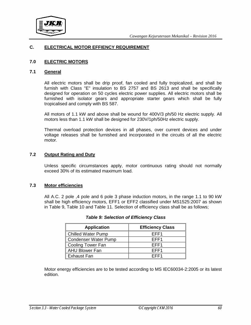
Cawangan Kejuruteraan Mekanikal – Revision 2016
Section 3.3 - Water Cooled Package System © Copyright CKM 2016 60
C. ELECTRICAL MOTOR EFFIENCY REQUIREMENT
7.0 ELECTRIC MOTORS
7.1 General
All electric motors shall be drip proof, fan cooled and fully tropicalized, and shall be furnish with Class "E" insulation to BS 2757 and BS 2613 and shall be specifically designed for operation on 50 cycles electric power supplies. All electric motors shall be furnished with isolator gears and appropriate starter gears which shall be fully tropicalised and comply with BS 587. All motors of 1.1 kW and above shall be wound for 400V/3 ph/50 Hz electric supply. All motors less than 1.1 kW shall be designed for 230V/1ph/50Hz electric supply. Thermal overload protection devices in all phases, over current devices and under voltage releases shall be furnished and incorporated in the circuits of all the electric motor.
7.2 Output Rating and Duty
Unless specific circumstances apply, motor continuous rating should not normally exceed 30% of its estimated maximum load.
7.3 Motor efficiencies
All A.C. 2 pole ,4 pole and 6 pole 3 phase induction motors, in the range 1.1 to 90 kW shall be high efficiency motors, EFF1 or EFF2 classified under MS1525:2007 as shown in Table 9, Table 10 and Table 11. Selection of efficiency class shall be as follows;
Table 9: Selection of Efficiency Class Motor energy efficiencies are to be tested according to MS IEC60034-2:2005 or its latest edition.
Application Efficiency Class Chilled Water Pump EFF1 Condenser Water Pump EFF1 Cooling Tower Fan EFF1 AHU Blower Fan EFF1 Exhaust Fan EFF1

Cawangan Kejuruteraan Mekanikal – Revision 2016
Section 3.3 - Water Cooled Package System © Copyright CKM 2016 61
Table 10: Efficiency Class Definition for 2-Pole Motors (MS 1525:2014)
Motor Capacity (kW)
Motor Efficiency (%) Motor Class IE3 Motor Class IE2 Motor Class IE1
0.75 80.7 77.4 72.1 1.1 82.7 79.6 75.0 1.5 84.2 81.3 77.2 2.2 85.9 83.2 79.7 3 87.1 84.6 81.5 4 88.1 85.8 83.1
5.5 89.2 87.0 84.7 7.5 90.1 88.1 86.0 11 91.2 89.4 87.6 15 91.9 90.3 88.7
18.5 92.4 90.9 89.3 22 92.7 91.3 89.9 30 93.3 92.0 90.7 37 93.7 92.5 91.2 45 94.0 92.9 91.7 55 94.3 93.2 92.1 75 94.7 93.8 92.7 90 95.0 94.1 93.0
110 95.2 94.3 93.3 132 95.4 94.6 93.5 160 95.6 94.8 93.8 200 95.8 95.0 94.0 220 95.8 95.0 94.0 250 95.8 95.0 94.0 300 95.8 95.0 94.0 330 95.8 95.0 94.0 375 95.8 95.0 94.0

Cawangan Kejuruteraan Mekanikal – Revision 2016
Section 3.3 - Water Cooled Package System © Copyright CKM 2016 62
Table 11: Efficiency Class Definition for 4-Pole Motors
(MS 1525:2014)
Motor Capacity (kW)
Motor Efficiency (%) Motor Class IE3 Motor Class IE2 Motor Class IE1
0.75 82.5 79.6 72.1 1.1 84.1 81.4 75.0 1.5 85.1 82.8 77.2 2.2 86.7 84.3 79.7 3 87.7 85.5 81.5 4 88.6 86.6 83.1
5.5 89.6 87.7 84.7 7.5 90.4 88.7 86.0 11 91.4 89.8 87.6 15 92.1 90.6 88.7
18.5 92.6 91.2 89.3 22 93.0 91.6 89.9 30 93.6 92.3 90.7 37 93.9 92.7 91.2 45 94.2 93.1 91.7 55 94.6 93.5 92.1 75 95.0 94.0 92.7 90 95.2 94.2 93.0
110 95.4 94.5 93.3 132 95.6 94.7 93.5 160 95.8 94.9 93.8 200 96.0 95.1 94.0 220 96.0 95.1 94.0 250 96.0 95.1 94.0 300 96.0 95.1 94.0 330 96.0 95.1 94.0 375 96.0 95.1 94.0

Cawangan Kejuruteraan Mekanikal – Revision 2016
Section 3.3 - Water Cooled Package System © Copyright CKM 2016 63
Table 12: Efficiency Class Definition for 6-Pole Motors
(MS 1525:2014)
Motor Capacity (kW)
Motor Efficiency (%) Motor Class IE3 Motor Class IE2 Motor Class IE1
0.75 78.9 75.9 70.0 1.1 81.0 78.1 72.9 1.5 82.5 79.8 75.2 2.2 84.3 81.8 77.7 3 85.6 83.3 79.7 4 86.8 84.6 81.4
5.5 88.0 86.0 83.1 7.5 89.1 87.2 84.7 11 90.3 88.7 86.4 15 91.2 89.7 87.7
18.5 91.7 90.4 88.6 22 92.2 90.9 89.2 30 92.9 91.7 90.2 37 93.3 92.2 90.8 45 93.7 92.7 91.4 55 94.1 93.1 91.9 75 94.6 93.7 92.6 90 94.9 94.0 92.9
110 95.1 94.3 93.3 132 95.4 94.6 93.5 160 95.6 94.8 93.8 200 95.8 95.0 94.0 220 95.8 95.0 94.0 250 95.8 95.0 94.0 300 95.8 95.0 94.0 330 95.8 95.0 94.0 375 95.8 95.0 94.0

Cawangan Kejuruteraan Mekanikal – Revision 2016
Section 3.3 - Water Cooled Package System © Copyright CKM 2016 64
7.4 Power Factor Requirement
All motor from 2 hp. to 100 hp. shall have a power factor of not less than 0.85 at 80% loading. Motors over 100 hp. shall have a power factor of not less than 0.90 at 80% loading. The above condition is to be achieved by power factor improvement equipment or devices. However, if the power factor correction is done other than at the load, than the cabling, electrical switching protection devices between the load and the point of correction shall be rated according to the worst power factor condition that they may be subjected to. Power factor improvement equipment used shall conform to IEC 70/70A standards and shall be suitable for continuous operation at a normal voltage of 400V (+10%, -6%) 50Hz, 3 phase. Capacitors used shall be dry type with self-healing properties and discharge devices. Loss shall not exceed 0.5 kVAr. When automatic power factor correction bank is used, the regulator with the required number of steps should also incorporate no volt protection relay, anti-hunting relay and a manual and automatic control switch. The regulator should be set to respond to kVAr need of the system with no hunting. The regulator shall have LED display to show the number of steps switched ON at any one time and settings for the sensitivity value and the desired power factor. Current transformer to suitable ratio shall be rated at 15 VA and minimum accuracy of Class 1. A kW-hr meter and a kVAr meter shall be incorporated in switchboards with a connected total load of 50 kW and above. This Contractor shall be liable to pay any surcharge, or part thereof, levied by the Tenaga Nasional as a consequence of low power factor of the installed equipment.

Cawangan Kejuruteraan Mekanikal – Revision 2016
Section 3.3 - Water Cooled Package System © Copyright CKM 2016 65
8.0 NOISE AND VIBRATION CONTROL
This section of specification specifies the basic requirement that the noise and vibration isolation control for the mechanical equipment which must be satisfied in order to be considered for the installation.
All mechanical plant and services shall be installed in accordance with the methods of installation and precautions stated herein, and such additional precautions as may be necessary to ensure that the operation of the plant does not result in noise levels or vibration amplitudes beyond the specified limits.
8.1 DESCRIPTION OF SYSTEM
The work specified under this section shall include but not necessarily limited to the following:
1. All noise and vibration generated by mechanical equipment shall be isolated from the
building structure. 2. All piping and ductwork in the building which is connected to vibration isolated
equipment shall be isolated at connections to the building structure. 3. All piping and ductwork in equipment rooms and up to 15m from vibrating equipment
shall be isolated from the building structure by means of noise and vibration isolation hanger, guides and supports.
4. All piping and ductwork vertical risers shall be isolated from the building structure by
means of noise and vibration isolation guides and supports.
5. All piping and ductwork to be isolated according to this section of the specifications shall freely pass through walls and floors without rigid connections. Penetration points shall be sleeved or otherwise formed to allow passage of piping or ductwork, and maintain a minimum of 25mm (1”) and maximum of 50mm (2") clearance around the outside surfaces. This clearance space shall be tightly packed with fibrous material or with engineered pipe penetration seals and shall be caulked airtight and water proof after installation of the piping or ductwork.
The whole of the work, including the particulars and/or deviations shown on the drawings and/or specified in the following clauses shall be in accordance with the appropriate ASHRAE Standards or such other National Standards as may be approved by the SO.

Cawangan Kejuruteraan Mekanikal – Revision 2016
Section 3.3 - Water Cooled Package System © Copyright CKM 2016 66
8.2 DESIGN STANDARDS AND VERIFICATIONS
The design of noise and vibration control equipment shall comply and not limited to the following Codes and Authorities:
1. ASHRAE 2003 (Chapter 47 – Noise and Vibration Control) 2. SMACNA 3. ARI 885 – 1998
Submittals and data requirements:
1. Descriptive Data: a. Schedules of equipment isolator. b. Catalogues and data sheets on vibration isolators.
2. Detailed and dimensioned Working Drawings including:
a. Details of equipment bases including dimensions, structural member sizes and support point locations.
b. Details of isolation hangers for ceiling hung equipment, piping and ductwork.
c. Details of mountings for floor supported equipment, piping and ductwork.
d. All hanger, mounting or pad drawings shall indicate deflections and model numbers as well as any other requirements in the specifications.
e. Spring diameters, rated loads and deflections, heights at rated load and closed height shall be provided for all springs shown in the submittals in tabular form.
f. Complete flexible connector details.
8.3 NOISE CONTROL
The sound power levels of the equipment shall be carefully examine as well as construction and installation methods to ensure that the equipment selection meets the sound level required.
All adjustments, modifications and testing shall be carried out to achieve the specified noise level. All supplied equipment from which noise is emanated shall be selected such that specified noise levels are not exceeded or shall be fitted with approved sound attenuation.
Optional room insulation using panel fitted to the all walls and doors with exceptional of fire rated door at the Mechanical Plant room shall be thermally and acoustically insulated with size and dimensions as per design requirement. All rotating machine shall be properly balanced and shall be designed with clearances and mechanisms suitable for the noise level requirements.

Cawangan Kejuruteraan Mekanikal – Revision 2016
Section 3.3 - Water Cooled Package System © Copyright CKM 2016 67
Rotating machinery shall be mounted on approved vibration isolating mountings. The mountings shall be protected from drips and damage, and where necessary, additional mass shall be fixed to the machinery to damp vibration.
The loading of the mounting shall be adequate to ensure correct operation. Materials used to seal the spaces containing the isolating materials shall be flexible so that vibration is not transmitted and the seal is not damaged.
All connections to rotating machinery shall be of flexible type. Duct connections shall be isolated by flexible nylon fabric or canvas connections.
Pipe connections shall be suitably flexed for the duty involved. Approved flexible connectors shall be provided where insufficient flexibility can be transmitted to the building structure. Flexibility connectors shall be so positioned that no stressed can be put on the pipes due to end reaction. Electric motors for all air conditioning unit and ventilation fans shall be quiet in operation to deliver noise level criteria as set out in Table 13 & 14. On completion of the installation, precise measurements of the noise levels in the various areas shall be made. Octave band sound pressure levels in the various areas within the building and at certain positions outside the building due to the operation of the equipment included in this contract shall not exceed the noise level criteria set out in the Table 13 & 14. In the event when the space noise exceeding maximum level of table 13 & 14 below, the level data should be allowed to be offset of 10dB /10 NC of background noise. Where dispute arises over the classification of any area under the following schedule the S.O. determination of the space type and function of the area, as listed in Table 13 & 14, shall be final.

Cawangan Kejuruteraan Mekanikal – Revision 2016
Section 3.3 - Water Cooled Package System © Copyright CKM 2016 68
Table 13: Recommended Noise Criteria (NC) – Room Criteria (RC) and Maximum Sound
Pressure Level (Lp) for Different Indoor Activity.
Type of Area Max Level
NC-RC Level Lp (dBA)
RESIDENCES
Residences, Apartment, Condominium 35 40 HOSPITALS & CLINICS Private rooms 35 40 Operating rooms 40 45 Wards, corridors 40 45 Laboratories 40 45 Lobbies, waiting rooms 45 50 Washrooms, toilets 50 55 OFFICES Board rooms 30 35 Conference rooms 35 40 Teleconference rooms 25 30 Executive offices 40 45 General offices 40 45 Reception rooms 45 50 General open offices 45 50 Drafting rooms 45 50 Halls & corridors 60 65 Tabulation and computation areas 50 55 AUDITORIUMS Multi-purpose halls 30 35 Lecture halls 35 40 Planetariums 35 40 Lobbies 45 50 LABORATORIES (with fume hoods)
Testing/research, minimal speech communication 55 60
Research, extensive telephone use, speech communication 50 55
Group Teaching 45 50

Cawangan Kejuruteraan Mekanikal – Revision 2016
Section 3.3 - Water Cooled Package System © Copyright CKM 2016 69
Table 14: Recommended Noise Criteria (NC) – Room Criteria (RC) and Maximum Sound
Pressure Level (Lp) for Different Indoor Activity (cont’).
Type of Area Max Level
NC-RC Level Lp (dBA)
PERFORMING ARTS SPACES Drama Theaters 25 30 Concert and recital halls 25 30 Music Teaching Studios 25 30 Music Practice Rooms 35 40 MASJID / RUMAH IBADAT 35 40 SCHOOLS Lecture/Classrooms 40 45
Classrooms up to 750 ft2 [75 m2] 40 45
Classrooms over 750 ft2 [75 m2] 35 40
Lecture rooms for more than 50 (unamplified speech) 35 40
Laboratories 45 50 Recreation halls 50 55 Corridors & halls 50 55 PUBLIC LIBRARIES Libraries, museums 40 45 COURT ROOMS 40 45 i) Unamplified speech 35 40 ii) Amplified speech 40 45 RESTAURANTS, CAFETARIA Restaurants 45 50 Cafeterias 50 55 INDOOR SPORTS ACTIVITIES Gymnasiums 45 50 School and college gymnasiums 50 55
Large seating capacity spaces (with amplified speech) 55 60
AIRPORT Tickets sales offices 40 45 Lounges, waiting rooms 50 55 OUTSIDE MECHANICAL PLANT ROOM 1m away from external wall 70 75

Cawangan Kejuruteraan Mekanikal – Revision 2016
Section 3.3 - Water Cooled Package System © Copyright CKM 2016 70
8.4 VIBRATION CONTROL
The vibration isolation shown on the drawings and Specification is as per minimum requirement. The installed equipment isolator shall be able to damp the vibration to the magnitude as per manufacturer’s recommendation. All vibration isolation shall be mounted on vibration isolators and complete with the flexible connections to prevent the transmission of vibration and noise to the building structure. Vibration isolators shall be selected in accordance with the weight distribution. Mountings installed outdoor shall be protected from corrosion as per recommended by manufacturer with a minimum of cold galvanizing paint if not specified. For corrosive environment, the minimum requirement shall be of hot dipped galvanized. The isolators installed for all mechanical equipment shall have a minimum deflections as per listed in the Vibration Isolators in Table 15 below. Any dispute arises in Table 15; all decision shall be referred and decided by S.O.
Table 15: Vibration Isolators Schedule
Equipment Isolators Remarks Centrifugal, Screw and Reciprocating Chiller
1. Restrained type steel spring in series with a layers on top and bottom plate each 9.0mm minimum thick neoprene pads / natural rubber. 1.1 When equipment on stable
ground minimum deflection is 19mm.
1.1 1.2 When equipment on concrete slab above floor level the minimum deflection is 38mm.
2.1
a) There should not be any rigid ties to any structure. All connection shall be flexible.
b) All pipe work within the plant room shall have steel spring hangers of min 25 mm total static deflections in series with neoprene.
Chilled Water Pump, Condenser Water Pump and All Other (End Suction, Split Casing, and Others)
1. Un-housed type steel spring in series with a layer of 9.0mm minimum thick neoprene pads / natural rubber. 1.1 When equipment on stable
ground minimum deflection is 19mm.
1.2 When equipment on concrete slab above floor level the minimum deflection is 38mm.
2. Inertia block shall be according to operation weight ratio (min 1:1.2 ratio) and min 150mm thick.
a) There should not be any rigid ties to any structure. All connection shall be flexible.
b) All pipe work within the plant room shall have steel spring hangers of min 25 mm total static deflections in series with neoprene.
c) The inertia blocks shall be large enough to support the pipe work including the first elbow.

Cawangan Kejuruteraan Mekanikal – Revision 2016
Section 3.3 - Water Cooled Package System © Copyright CKM 2016 71
Cooling Towers 1. Restrained type steel spring in series with a layers on top and bottom plate each 9.0mm minimum thick neoprene pads / natural rubber. 1.1. When equipment on stable
ground minimum deflection is 19mm.
1.2. When equipment on upper floor or critical area above floor level the minimum deflection is 89mm.
a) There should not be any rigid ties to any structure. All connection shall be flexible.
b) All pipe work connected to cooling towers shall have flexible joints.
Air Handling Unit 1. A layer of minimum 9.0mm thick neoprene pad
2. For critical area, un-housed type steel springs in series with a layer of 9.0mm minimum thick neoprene pads / natural rubber.
a) There should not be any rigid ties to any structure. All connection shall be flexible.
b) All pipe work within the plant room shall have steel spring hangers of min 25 mm total static deflections in series with neoprene.
c) Pipe work to equipment shall have flexible joints.
d) All ductwork to equipment shall have flexible connection.
Fan coil units (Up to 7.5kW)
1. Spring isolators (floor or hanger type) of minimum 19mm deflections.
a) There should not be any rigid ties to any structure. All connection shall be flexible
b) All ductwork to equipment shall have flexible connection
Fan Coil Units (11kW and above)
1. Spring isolators (floor or hanger type) of minimum 89mm deflections.
Condensing Units 1. Floor mounted unit – A layer of minimum 9.0mm thick neoprene pad.
2. Suspended type – spring isolators of minimum 38mm deflections.
a) There should not be any rigid ties to any structure. All connection shall be flexible.
b) Pipe work to equipment shall have flexible connections.
Mechanical Ventilation Fan (Axial, Centrifugal, Fan Heads, Cabinet Fans, Fan Sections ) – up to 560mm dia
1. Double deflection steel spring with neoprene element in shear hanger of supports of min 19mm deflections.
a) There should not be any rigid ties to any structure. All connection shall be flexible.
b) All ductwork to equipment shall have flexible connection (if any).
Mechanical Ventilation Fan (Axial, Centrifugal, Fan Heads, Cabinet Fans, Fan Sections ) – 610mm dia and above
1. Un-housed type steel spring in series with a layer of 9.0mm minimum thick neoprene pads / natural rubber with minimum 19mm deflection.
2. Inertia block shall be according to operation weight ratio (min 1:1.2 ratio) and min 150mm thick.
Propeller Fan 1. A layer of minimum 9.0mm thick neoprene pad.
a) There should not be any rigid ties to any structure. All connection shall be flexible.

Cawangan Kejuruteraan Mekanikal – Revision 2016
Section 3.3 - Water Cooled Package System © Copyright CKM 2016 72
8.5 PIPING
Equipment installed on vibration isolators exhibits some motion or movement from pressure thrusts during operation. Vibration isolators have even greater movement during starting-up and shutdown. The piping system shall be flexible enough to:
i) Reduce vibration transmission along the connected piping.
ii) Permit equipment movement without reducing the performance of
vibration isolators.
iii) Accommodate equipment movement or thermal movement of piping at connections without imposing undue strain on the connections and equipment.
In general, water pipes shall be sized to maintain average flow velocities of not more than 2.2 m/s. Flow velocity at 12 m/s maximum for pipe 50mm and smaller. A pressure drop limitation of 4 ft of water per 100 ft of pipe length with a maximum velocity of 3.0 m/s for larger pipe sizes. Isolation hangers shall be used for all piping in mechanical equipment rooms and up to 15 m from vibrating equipment. The first three isolation hangers/supports from all mechanical equipment should provide the same deflection as the equipment isolators, with a maximum limitation of 50mm deflection. The remaining isolation hangers within 15 m should be spring or combination spring and rubber with minimum of 20mm deflection.
The first vertical pipe riser entering the building shall be supported by spring isolators designed to support the riser filled with water, if it is a water line. Assigned loads must be within the building design limits at the support points. Neutral central resilient anchors close to the center of the run shall direct movement up and down. The anchors and guides must be rigidly attached to the structure and shall be capable of holding an upward force equal to the water weight when the system is drained. The remaining vertical pipe riser shall be supported by natural rubber/ neoprene pad with minimum thickness of 9 mm. All pipe penetrations through wall; floors and ceiling shall be isolated from direct contact with the structure.

Cawangan Kejuruteraan Mekanikal – Revision 2016
Section 3.3 - Water Cooled Package System © Copyright CKM 2016 73
8.6 DUCTWORK
The main supply air ductwork shall be internally insulated with acoustic insulation for the length as specified in the tender drawing. If unspecified, it shall be taken as 5m from the fan or 1m beyond the first bend, whichever is the longest. Isolation hangers shall be used for all ductwork in mechanical equipment rooms and up to 15 m from vibrating equipment. The first three isolation hangers/supports from all mechanical equipment should provide the same deflection as the equipment isolators, with a maximum limitation of 50mm deflection. The remaining isolation hangers within 15 m should be spring or combination spring and rubber with minimum of 20mm deflection. The acoustic performance of the fiberglass internal insulation of duct shall not be less than those stated in the Table 16 below for the thickness indicated and in accordance to BS EN 20354 / BS 3638. The air erosion resistance for the internal insulation shall not be less than 2500 fpm and comply with ASTM C1071-05e7 and ASTM C1534-07.
Table 16: Absorption Coefficient
Frequency, Hz 125 250 500 1000 2000 4000 NRC
Absorption Coefficient (25mm) 0.08 0.20 0.56 0.93 0.84 0.92 0.63
Absorption Coefficient (50mm) 0.19 0.49 0.87 0.97 0.97 1.04 0.83

Cawangan Kejuruteraan Mekanikal – Revision 2016
Section 3.3 - Water Cooled Package System © Copyright CKM 2016 74
9.0 INDOOR AIR QUALITY (IAQ) REQUIREMENTS
9.1 General
This section of specification specifies the basic requirement of IAQ to provide guidance on improving the indoor air quality (IAQ) and to set minimum standard for selected parameters that will avoid discomfort and/or adverse health effect among employees and other occupants of an indoor or enclosed environment served by air conditioning and mechanical ventilation (ACMV) system installed in the building. Good indoor air quality (IAQ) is desired for a healthy indoor environment. Poor indoor air quality can cause a variety of health problems ranging from temporary to long term. Health problems commonly associated with poor IAQ include allergic reactions, respiratory problems, eye irritation, sinusitis, bronchitis and pneumonia.
9.2 Design Standard and Verifications
The requirement of IAQ shall comply but not limited to the following Codes and Authorities: a. ANSI/ASHRAE Standard 62.1 – 2007 or latest b. Industry Code of Practice on Indoor Air Quality 2010 or latest by Department of
Occupational Safety and Health, Ministry of Human Resources, Malaysia.
9.3 Indoor Air Quality Requirements
9.3.1 Parameters to Indicate IAQ Status
In this specification of basic requirement of IAQ, the parameters to indicate whether an indoor environment is comfortable and healthy or otherwise can be summarised as follows: a) Chemical contaminants such as Carbon Dioxide and Respirable Particulate. b) Physical conditions such as air temperature, air velocity and air humidity.
9.3.2 Duty to control exposure
During the testing and commissioning period of the air conditioning and mechanical ventilation system, the Contractor shall ensure that all readings taken for the working environment shall conform to the acceptable range as specified in Table 16 and Table 17 below or Schedule of Design Requirement, whichever is more stringent:

Cawangan Kejuruteraan Mekanikal – Revision 2016
Section 3.3 - Water Cooled Package System © Copyright CKM 2016 75
Table 17: Acceptable Range for Specific Physical Parameters
(Industry Code of Practice on Indoor Air Quality 2010)
Parameter Acceptable Range
a. Air temperature 23°C - 24°C b. Relative humidity 40 – 70% c. Air movement 0.15-0.5 m/s
Table 18: Acceptable Limits of Indoor Air Contaminants (IIndustry Code of Practice on Indoor Air Quality 2010)
Indoor Air Contaminants
Acceptable Limits
ppm mg/m3 cfu/m3
Chemical contaminants -
0.15
-
a.
Respirable particulates
b.
Carbon monoxide
10
Biological contaminants
a. Total bacterial counts
500*
b. Total fungal counts
1000*
Ventilation performance indicator
C1000
-
-
a. Carbon dioxide
• For chemical contaminants, the limits are eight-hour time-weighted average airborne concentrations.
• C (in Table 17) is the ceiling limit that shall not be exceeded at any time. Readings above 1000 ppm are indication of inadequate ventilation.
• * Excess of bacterial counts does not necessarily imply health risk but serve as an indicator for further investigation.

Cawangan Kejuruteraan Mekanikal – Revision 2016
Section 3.3 - Water Cooled Package System © Copyright CKM 2016 76
9.4 Control of Indoor Air Quality
The control of indoor air quality is required to enhance the quality of indoor air that the AHU/FCU serves to meet the room condition as per IAQ requirement. Selection of control for the indoor air quality system shall be as per Schedule of Design Requirements and specification below:
9.4.1 Treatment for Air Handling Unit Cooling Coils and Fins
All cooling coils and fins, filter and condensate drain pans shall be treated with a non-toxic, non-corrosive, bio-degradable, hospital grade multiple enzyme having a PH value of 7.0. It shall have the capability of penetrate deep and clear off any blockages within the coils and subsequently form a protective coating. It shall be able to breakdown and digest micro-organism, bacteria, fungus and mould contaminants and prevent microbial colonisation from forming on the treated surface and to maintain the internal air quality of the conditioned space. The enzyme shall not cause chemical degradation of the copper tubes and the aluminium fins. Treatment shall have a residual effect and shall prevent microbial colonisation from forming. The contractor shall produce a comprehensive Microbiological Report of before and after treatment based on the microbiological swab test on all coil surfaces, filters, drain pans and ACMV room surfaces. The test shall be carried out by contractor every four (4) months of the twelve (12) months period after the awarding of Certificate of Completion and Compliance (CCC).The government reserved the right to engage an independent laboratory for the purpose of comparisons, as and when necessary.
9.4.2 Ultraviolet Air Purifier System
General
The designated air conditioned area shall be treated by the air purifier system that used Ultraviolet Germicidal Irradiation (UVGI) as the main medium of eliminating contaminants. The Ultra Violet Air Purifier system shall be installed either within the AHU, FCU or ductwork to provide a complete air purification and sterilization by supplying clean and healthy air to the conditioned space. Appointment of Approved Supplier/Manufacturer
The contractor shall appoint a competent supplier/manufacturer to supply the ultraviolet air purifier system and experienced in the specific area as required by the government.

Cawangan Kejuruteraan Mekanikal – Revision 2016
Section 3.3 - Water Cooled Package System © Copyright CKM 2016 77
The appointed supplier/manufacturer shall be responsible for the approval of design, supervision and testing of the ultraviolet air purifier system. The contractor shall take full and unequivocal responsibility for the suitability, functionality, maintainability and safety of the design and for the adequacy, stability and safety of all site operations and methods of construction.
System Design and Equipment
The contractor at design stage shall consider and address the size and capacity of AHU and ducting system to provide relevant size of UV Air Purifier system. The installation shall be designed and installed accordingly to ensure the UV air purifier works well in preventing and eliminating both chemical and biological contaminants. The designated Ultraviolet Air Purifier System shall be of flexible assembly consist of any part of the following components but not limited to: i. Ultra-Violet Germicidal Irradiation (UVGI) assembly. ii. Electronic Purification & Sterilisation assembly c/w controls. iii. Oxidizing Ultraviolet quartz lamp (Odour elimination). iv. Integrated Air Filtration system The system equipment offered shall be a complete system supplied from one manufacturer. Otherwise, the manufacturer/supplier shall submit letter of undertaking to provide the technical support and be responsible for all system compatibility and performance The contractor shall include the cost to carry out appropriate Indoor Air Quality assessment by a competent person/body (IAQ Assessor). The assessment shall be carried out by contractor after the awarding of Certificate of Completion and Compliance (CCC).
System Operation The Ultra Violet Air Purifier system shall be able to eliminate particulate (filtering), gas (adsorption), chemical and biological contaminants such as mould and chemical odours of the indoor air contaminants. The basic components of the UVGI system shall include but not limited to electronic aluminum filters, electrodynamic carbon processor, UVC germicidal lamps, UVV oxidizing quartz lamps and the control system.
Warranty The high intensity UV lamp shall have warranty of minimum 6,000 hours.
Cawangan Kejuruteraan Mekanikal – Revision 2016
Section 3.3 - Water Cooled Package System © Copyright CKM 2016 78
10.0 ELECTRICAL WORKS 10.1 GENERAL
The Contractor shall carry out all electrical work necessary for the efficient, safe and satisfactory operation of the plant detailed elsewhere in the specification and shall supply, install and connect all motors, switchboards, switchgears and all necessary equipment and materials except where it is stated in the specification that materials are to be supplied or work is to be carried out by others. All electrical equipment supplied shall be of the first grade as regards design and fully competent electrician of appropriate grades shall only carry out manufacture and installation. All the electrical work shall use JKR approved product listed on J-MAL / Electrical Material Approval List. The Contractor shall provide the following electrical equipments and services: (a) All electric motors, starters, cable boxes and isolating switches for the air
conditioning and ventilation services. (b) Conduit, cable tray, cabling and control wiring from the electrical in the sub-
switchboards to the air conditioning switchboards (control panels). (c) Conduit, cable tray, cabling and control wiring from the air conditioning
switchboards (control panels) to the various items of air conditioning and ventilation equipments.
(d) All control equipments, control wiring and associated works.
(e) Conduit and wiring including control switches and fused spare outlets as
indicated in the tender drawings. (f) Relays for FF detectors in the AC Control Panel/Switchboard.
The Contractor shall be required on completion of the electrical installation to provide in a glazed frame a complete "as installed" wiring diagram identifying all the control circuit and the various colour-coding. The diagram endorsed by a competent person or manufacturer. The following works shall be carried out under other specialist work: (a) Supply, installation and connection of the sub-mains to main air conditioning plant
switchboard and to the isolators in the sub-switchboards for the AHUs. (b) Lighting and power socket outlets in the plant rooms.
Cawangan Kejuruteraan Mekanikal – Revision 2016
Section 3.3 - Water Cooled Package System © Copyright CKM 2016 79
Unless specified elsewhere, all equipment, apparatus, appliances and accessories for low voltage electrical installation shall be rated for operation on a 240/415 V (within the tolerance as defined in MS IEC 60038 : 230/400V (+10%,-6%), 3 phase, 50 Hz. system with solidly earthed neutral. All standard shall conform to the latest MS, MS IEC, IEC, BS EN, BS and/or EN standard.
10.2 MAIN AIR CONDITIONING SWITCHBOARD
10.2.1 TYPES OF AIR CONDITIONING SWITCHBOARD
The types of switchboard shall be as specified in the Drawings and/or Schedule of Design Requirements shall be of the following types: (a) Self-contained, floor mounted, flush fronted, metalclad cubicle type suitable for
front and rear access;
(b) Self-contained, floor mounted, flush fronted, metalclad cubicle type suitable for front access ;
(c) Wall mounted metalclad type suitable for front access. The switchboards shall house their air circuit breakers, moulded case circuit breakers, fuse switches, switch fuses, isolators, contactors, busbars, meters, protective relays, selector switches, indicating lamps, current transformers, cable terminating boxes, cable glands, anti-condensation heaters complete with automatic thermostats and isolators and all other necessary items of equipment whether specified hereinafter or in the Drawings or not, suitable for operation on a 400/230 V (+10%, -6%), 3 phase, 4 wire, 50 Hz. system with solidly earthed neutral. Unless otherwise specified elsewhere, the switchboards shall be capable of withstanding fault condition of not less than 50 kA at 415 V for 1 s as defined in IEC 60439-1. The switchboards shall comply with IEC 60439-1 and the degree of protection shall be IP41 in accordance to MS IEC 60529. Outdoor switchboard shall also comply with MS IEC 60439-5 with protection degree of IP54 in accordance to MS IEC 60529.

Cawangan Kejuruteraan Mekanikal – Revision 2016
Section 3.3 - Water Cooled Package System © Copyright CKM 2016 80
Type testing for switchboard:-
Table 19: Type Testing for Switchboard As Per Categorization
Category Current Rating Registration & Type Test Report
l ll
lll
l ≤ 600A
600A < l ≤ 2000A
l > 2000A
SuruhanjayaTenaga SuruhanjayaTenaga& Partial Type Test accordance with MS IEC 60439-1
(i) Short Circuit Test (Clause:80203) (ii) Temperature Rise Test (Clause:8.2.1)
SuruhanjayaTenaga& Full Type Test accordance with MS IEC 60439-1
Routine tests on the switchboard shall be carried out before delivery to site. The main circuits and the auxiliary circuits shall be tested to verify dielectric properties with power-frequency test voltage of 2500 Vac for 1 minute and insulation resistance under test voltage of 1000 V. Routine tests shall include inspection and checking of wiring, electrical continuity of the protective circuits, connections and effectiveness of mechanical actuating elements and interlock. Test Results or Certificate duly certified by Competent Person as in Electricity Regulations 1994 shall be issued for every switchboard supplied and installed.
10.2.2 POWER FACTOR REQUIREMENT FOR MAIN SWITCHBOARD All switchboard equipment such as motor, transformer, air conditioners, fans, refrigerator, welders fluorescent light, etc. below 132kVA. shall have a power factor of not less than 0.85 at 80% loading. Switchboard equipment’s with capacity over 132 kVA shall have a power factor of not less than 0.90 at 80% loading. The above condition is to be achieved by power factor improvement equipment or devices. However, if the power factor correction is done other than at the load, than the cabling, electrical switching protection devices between the load and the point of correction shall be rated according to the worst power factor condition that they may be subjected to. Power factor improvement equipment used shall conform to IEC 70/70A standards and shall be suitable for continuous operation at a normal voltage of 400V (+10%, -6%) 50Hz, 3 phase.

Cawangan Kejuruteraan Mekanikal – Revision 2016
Section 3.3 - Water Cooled Package System © Copyright CKM 2016 81
Capacitors used shall be dry type with self-healing properties and discharge devices. Loss shall not exceed 0.5 kVAr. When automatic power factor correction bank is used, the regulator with the required number of steps should also incorporate no volt protection relay, anti-hunting relay and a manual and automatic control switch. The regulator should be set to respond to kVAr need of the system with no hunting. The regulator shall have LED display to show the number of steps switched ON at any one time and settings for the sensitivity value and the desired power factor. Current transformer to suitable ratio shall be rated at 15 VA and minimum accuracy of Class 1. A kW-hr meter and a kVAr meter shall be incorporated in switchboards with a connected total load of 50 kW and above. This Contractor shall be liable to pay any surcharge, or part thereof, levied by the Tenaga Nasional as a consequence of low power factor of the installed equipment.
10.2.3 ENCLOSURES GENERAL
Switch operating handles shall be interlocked with the compartment door so that the door may not be opened until the switch is off. Light shall be clearly visible at a distance on clear day. The following shall be incorporated in Switchboard but not limited to:
(1) Duty & Standby Pump:
i) Red, Yellow and Blue lights for phase indication in duplicate.
ii) Red flashing light for A/C FAIL and PUMP ON MANUAL.
iii) Green light for PUMP RUN.
iv) Yellow light for PUMP TRIP.
v) START and STOP push button.
vi) Switch off for A/C isolate and AUTO MANUAL selector switch.
vii) An ammeter and voltmeter shall be provided.
viii) MANUAL START push button.
ix) Amber light for AUTO ON, AUTO CRANK ON, MANUAL ON, and AUTO CRANK FAIL.
x) Green light signals shall be provided on single horizontal alignment spaced adequately to show that the supply is normal. They are A/C ON, CHARGER ON, D/C ON.

Cawangan Kejuruteraan Mekanikal – Revision 2016
Section 3.3 - Water Cooled Package System © Copyright CKM 2016 82
(2) A relay shall be provided in the switchboard to stop the pump when the water
level in the water tank is at low water level and prevent from being switch on again until the water level reach start level.
10.2.4 SELF-CONTAINED FLOOR MOUNTED CUBICLE SWITCHBOARDS
The framework of the switchboard shall be fabricated from rolled steel sections of thickness not less than 2.5 mm and shall be self-supporting when assembled, uniform in height and depth from front to back. The rigid construction shall be designed to withstand without any sag, deformation or warping, the loads likely to be experienced during normal operating, maintenance or maximum fault condition. The front shall be provided with covers/doors of box formation. The rear shall be provided with hinged removable doors of box formation. The rear doors shall be of double-leaf type with rebated edges and each leaf should preferably not be wider than 450 mm. Each leaf of door shall have 2 pairs of approved hinges. The door shall be fitted with approved type of surface-mounted espagnolette or cremone bolts complete with approved locking device operated by a satin chrome lever handle at the centre fixing. The top and sides shall be of removable panels. Cover plates with openings for cable entry shall be provided at the base of the switchboard. All panels, covers and doors shall be fabricated from sheet steel of thickness not less than 2.0 mm and so constructed as to provide a clear, flush and pleasing appearance. The panels, covers and front doors shall be secured to the enclosure by means of chromed type of screws with cylindrical knurled head complete with retaining clips. Welded cross struts shall not be used. The switchboard shall be dust and vermin proof. All covers and doors shall be provided with grommets and dust seals to exclude dust and dirt. Louvers or ventilation vent with filter shall be provided at the sides and back for adequate ventilation. Precaution shall be taken to prevent overheating due to hysteresis and eddy current using non-ferrous plate (for single core cable). All edges shall be rounded. Serrated star washers shall be fitted to ensure satisfactory earthing of the front cover. All indicating instrument which need to be read by the operator shall not be located higher than 2m above the base of the switchboard. All operating devices such as handle, push buttons, etc., shall be located at such a height that they can easily be operated, and in general, the centreline shall not be higher than 2m above the base of the switchboard.

Cawangan Kejuruteraan Mekanikal – Revision 2016
Section 3.3 - Water Cooled Package System © Copyright CKM 2016 83
In the case where building automation devices, transducers and relays are provided, they shall be separately housed in a compartment of the section of the switchboard. All wiring from the devices, transducers and relays shall be neatly arranged and connected to the terminal blocks with removal links mounted on rail. Terminals shall be identified and labelled in accordance with IEC 60445. A lockable tool compartment with keys and opening handle shall be provided at the lowest subsection of the switchboard. The switchboard shall undergo de-rusting treatment, anti-rust treatment with the exterior finished with epoxy dry-powder and oven baked semi-gloss beige colour and interior finished matt white. The switchboard shall be bolted to mild steel channel base or over concrete trench. The channel shall be anti-rusted and painted with a primer. There shall be a readily installed cable tray on the interior at both side panels for outgoing cable. All cables shall be rigidly secured using cable support bracket of non rotting material, before termination.
10.2.5 WALL MOUNTED SWITCHBOARDS
The switchboard shall be fabricated from sheet steel of thickness not less than 2.0 mm. The enclosure shall be of all welded construction with sheets bent where possible so as to minimise the number of welded joints. The four sides of the enclosure shall be returned at the front to facilitate fixing of front cover plates. The front cover plates or doors shall be of box formation and flanged to facilitate fixing to the enclosure. The front cover of the switchboard shall be provided with grummets and dust seal to exclude dust and dirt. Meshed louvre or ventilation vent with filter shall be provided at both sides for ventilation. All edges shall be rounded. Serrated star washers shall be fitted to ensure satisfactory earthing of the front cover. The switchboard shall undergo de-rusting treatment, anti-rust treatment and be finished with epoxy dry-powder and oven baked semi-gloss beige colour. The switchboard shall not be mounted directly to the wall structure. It shall be firmly bolted/ welded on to galvanised C-channel brackets which in turn shall be bolted to the wall or structure by means of bolts and nuts. The top of the switchboard shall not be higher than 2100mm and the bottom shall not be lower than 900mm from the floor.

Cawangan Kejuruteraan Mekanikal – Revision 2016
Section 3.3 - Water Cooled Package System © Copyright CKM 2016 84
10.3 ASSOCIATED COMPONENTS
Busbars shall be of hard drawn high conductivity copper of adequate rectangular cross section to carry continuously the specified current without overheating and also colored in accordance with the latest applicable British Standards. An earthen busbars of suitable cross section shall be run the full length at the base of the main switchboard. Connections from busbars to the circuit breakers, switchfuses and fuseswitches shall be effected by means of copper bars or rods securely clamped to the busbars and identified by means of coloured plastic sleeving to indicate the phase colours. All relays provided shall be heavy-duty pattern, unaffected by external vibration and capable of operation in any position. All meters and relays shall be fully tropicalised. Earth fault/over current relays with the delay characteristics shall be provided to trip circuit breakers as specified. Earth fault relay shall incorporate drop flag indicator with hand-reset contacts. All contactors and starters, relays and controllers shall be fitted on insulated panels. All incoming and outgoing circuit and in ring shall be brought to the contactors, starters, relays and controllers, via insulated terminal strips mounted within the metal cubicles, and all wiring between terminal strip and electrical equipment inside the control panel shall be neatly run and taped in accordance with the requirements of the Suruhanjaya Tenaga (ST).
10.4 AIR CIRCUIT BREAKERS (ACB)
ACB shall be of withdrawable metalclad, flush mounted, horizontal draw out isolation and air break type suitable for installing on cubicle type of switchboard. They shall be three or four poles type as specified and shall comply fully with IEC 60947-1 and 60947-2. They shall be ASTA or KEMA or other accredited laboratories certified for minimum rupturing capacity, rated short time withstand current, (lcw) of 50 kA at 415 V for 1 second or otherwise specified. They shall consist of quick-make, quick-break, mechanically and electrically trip free mechanism arranged to give double break in all poles simultaneously. The closing mechanism shall be of stored energy type, either manually or electrically charged. Mechanical `ON' and `OFF' or ‘|’ and ‘0’ indicators shall be provided. The tripping mechanism shall be equipped with push button for independent manual tripping and shall be stable and not being opened by shocks.

Cawangan Kejuruteraan Mekanikal – Revision 2016
Section 3.3 - Water Cooled Package System © Copyright CKM 2016 85
Each pole of the circuit breaker shall be provided with an arc chute to extinguish the arc drawn between the breaker contacts each time a breaker interrupts current, and interpole barriers to reduce arcing time for rapid deionization of the arc and guard against flash over. The contacts shall be renewable type. The operating mechanism and carriage shall have the following positions: - (a) Service - In this position the main and control contacts are engaged. (b) Test - In this position the main contacts are isolated but the control contacts are
still engaged. It shall be possible to check the correct operation of the control circuits without energising the main circuit.
(c) Isolated - Both main and control contacts are isolated. They shall be provided with marking to show the breaker positions with facility for padlocking the carriage in the Test and Isolated positions. They shall be equipped with the following interlock devices: - (a) Prevent withdrawal of breaker while the breaker is in closed position. (b) Prevent closure of breaker while the carriage is in any position between `fully
isolated' and `fully home'. The arrangement of the busbar connections shall be such that with the circuit breaker withdrawn, the life parts shall be protected, either by suitable shrouding or lockable shutters. Minimum four numbers (2-Normally-Open, 2-Normally-Close) double break type auxiliary contacts shall be provided. Mechanical interlocks and/or electrical interlocks, where specified, shall be provided. Mechanical interlock shall be of code key type, arranged to mechanically operate the trip mechanism latch so that the breaker can only be closed when the key is trapped in the lock. Electrical interlock shall be controlled by means of operation of auxiliary switches of another breaker designed to cut out the closing coils and mechanism of the parent breaker. Where used as bus-coupler, they shall be of 4 pole type and provided with electrical and/or mechanical interlocks as required so that it is not possible for the coupler to close with its associated main incoming supply breakers closed. The neutral of the 4 pole type ACB terminals shall be of the same size as the phase. The frame of ACB shall be bonded to the switchboard earthing bar using of 3mm x 25mm tinned copper tape.
Cawangan Kejuruteraan Mekanikal – Revision 2016
Section 3.3 - Water Cooled Package System © Copyright CKM 2016 86
10.5 MOULDED CASE CIRCUIT BREAKERS (MCCB)
MCCB shall comply with MS IEC 60947-2. They shall be fully tropicalised and suitable to be used up to an ambient temperature of 40 ºC, enclosed in glass-reinforced polyester moulded case and suitable for use on 240/415 V, 50 Hz. a.c. supply system. They shall be of the quick-make, quick-break type having manually operable toggle type handle. Permanent position indicators shall be provided to show status of the breaker. When tripping occurs, the handle shall be in the trip position midway between the 'ON' and 'OFF' or ‘I’ and ‘O’ position so as to provide positive indication of automatic interruption. The operating mechanism shall be non-tamperable. The MCCB shall have trip-free feature to prevent the breaker from being closed against fault conditions. Multipole MCCB shall have common-trip operating mechanism for simultaneous operation of all poles. The tripping units shall be one of the following types: - (a) Thermal-magnetic types with bimetallic elements for inversetime-delay overload
protection and magnetic elements for short circuit protection. (b) Solid state trip unit with adjustable overload protection and adjustable short circuit
protection with or without adjustable time-delay. An arc extinguisher shall be incorporated to confine, divide and extinguish the arc drawn between the breaker contacts each time a breaker interrupts current. The contacts shall be of non-welding type. If current limiting types of MCCB are used, they shall be equipped with current limiting device of either permanent self-resetting power fuse type or magnetic repulsion moving contact type. The current limiting device shall coordinate with the normal trip mechanism so that all fault and overload currents occurring within the safe capability of the MCCB shall cause the MCCB to open, and all currents occurring beyond the capability of the MCCB shall cause the current limiting devices to operate. If required, the MCCB shall have facilities for shunt trip, under-voltage/no-volt trip, externally connected earth fault protection, externally connected overcurrent protection etc. They shall also have auxiliary contacts, accessories etc. for indication, alarm and interlocking purposes if necessary. In area where is specified, and door interlocking facilities to prevent the panel door from being opened to access to the MCCB in closed position, shall be provided.

Cawangan Kejuruteraan Mekanikal – Revision 2016
Section 3.3 - Water Cooled Package System © Copyright CKM 2016 87
10.6 MINIATURE CIRCUIT BREAKERS (MCB)
MCB shall be of type approved by Suruhanjaya Tenaga and JKR.
Unless otherwise indicated in the Drawings and/or Schedule of Design Requirements, MCB shall have breaking capacity not less than 6kA (rms) and of C-type with class 3 energy limiting characteristics. They shall comply with MS IEC 60898-1 and/or MS IEC 60898-2, fully tropicalised and suitable for use on a 240/415 V, 50Hz. a.c. system and up to an ambient temperature of 40°C. They shall be quick-make, quick-break and trip free type complete with de-ion arc interrupters. The tripping elements shall be of thermal magnetic type with inverse time delay overcurrent and instantaneous short circuit characteristic. The respond to overload shall be independent of variations in ambient temperature. They shall be manually operated by means of toggle type handles having visual indication of whether the breaker is opened, closed or tripped. Multipole MCB shall be of all pole protected type and provided with common-trip mechanism for simultaneous operation of all the poles.
10.7 ISOLATING SWITCHES
Isolating switches or switch-disconnector shall be of metalclad or high impact insulating material (e.g. polycarbonate) type. They shall fully comply with MS IEC 60947-1 and MS IEC 60947-3. The degree of protection shall be IP54 for indoor installation and IP65 for outdoor installation. They shall be able to operate continuously at full current rating without de-rating, capable of making and breaking currents under normal condition and when in open position, providing isolation from source of electrical energy for reasons of safety. They shall be quick-make, quick-break type suitable for use on 240/415 V, 50Hz. a.c. system. They shall be provided with removable top and bottom end plates or knockouts for cable entry. The enclosure, the isolating mechanism and all other accessories shall be from the same manufacturer.
The enclosure for metalclad type shall comprise of heavy gouge steel plates rust protected and finished grey stove enamel. Front access doors for metalclad type, which is detachable, shall be fitted with dust-excluding gasket and shall be interlocked to prevent opening when the switch is ‘On’. However this interlock shall be able to be defeated by competent person for maintenance purpose. It shall be provided with, if required, facilities for lock-on and lock-off the operating handle.

Cawangan Kejuruteraan Mekanikal – Revision 2016
Section 3.3 - Water Cooled Package System © Copyright CKM 2016 88
10.8 CONTACTORS
Contactors shall comply with IEC 60947-1 and 60947-4-1. They shall be fully tropicalised, suitable to be used up to an ambient temperature of 40ºC and suitable for use on 230/400V (+10%, -6%)50Hz. A.C. supply system.
The contacts shall be of quick-make and quick-brake type, dust-proof and rust protected. They shall be utilisation category as per Table 20.
Table 20: IEC Utilization Categories
Current Utilization Category Typical Applications
AC
AC-1 Non Inductive or slightly inductive loads, resistance furnaces, heaters.
AC-2 Slip-ring motors : switching off
AC-3 Squirrel-cage motors: starting, switching off motors during running Most typical industrial application
AC-4 Squirrel-cage motors: starting, plugging¹, inching²
AC-5a Switching of electric discharge lamps
AC-5b Switching of incandescent lamps
AC-6a Switching of transformers
AC-6b Switching of capacitor banks
AC-7a Slightly inductive loads in household appliances: mixes, blenders
AC-7b Motor-loads for household applications: fans, central vacuum
AC-8a Hermetic refrigerant compressor motor control with manual resetting overloads
AC-8c Hermetic refrigerant compressor motor control with automatic resetting overloads
(1) Plugging – Stopping a motor rapidly by reversing the primary power connection.
(2) Inching – Energizing a motor repeatedly for short periods to obtain small
incremental movements.
The contactor shall have multiple contacts and unless otherwise specified shall be normally-open.

Cawangan Kejuruteraan Mekanikal – Revision 2016
Section 3.3 - Water Cooled Package System © Copyright CKM 2016 89
10.9 PROTECTION RELAYS
The protection device shall be of the type acceptable to the Supply Authority or Licensee and JKR. The protection relays shall be of panel flush mounting type. All relays shall comply with relevant parts of IEC 60255.
Overcurrent and earth fault protection shall be provided by externally connected current transformers.
Unless specified in the Drawing and/or Schedule of Design Requirements, electromechanical overcurrent and earth fault relay shall be of Inverse Definite Minimum Time (IDMT) type.
For overcurrent relay of IDMT induction disc type, current settings shall be from 50% to 200% adjustable in seven equal steps and time multiplier settings from 0.1 to 1.0 seconds adjustable continuously. Earth fault relay of IDMT induction disc type shall have current settings from 10% to 40% or rated current adjustable in seven equal steps time multiplier settings ranging from 0.1 to 1.0 adjustable continuously. Earth leakage relay (ELR) shall be of the type suitable for use on a 240/415 V,50 Hz. a.c. system and up to ambient temperature of 40ºC ELR shall be provided with test button for simulation of a fault, earth leakage LED indicator a reset button, protection against nuisance tripping due to transient voltage and d.c. sensitive. Unless otherwise specified in the Drawings and/or Schedule of Design Requirements, ELR shall be of adjustable current sensitivity and adjustable time delay type. The selectivity range for current sensitivity shall be 0.03A to 10A and the time delay selectivity range of 0 second to 1 second. ELR shall incorporate with matching balanced core current transformer and shunt trip coil for the circuit breaker to which it controls the tripping shall also be provided. Unless specified in the Drawings and/or Schedule of Design Requirements, the microprocessor based protection relays shall be rated at 240V/415V and operating voltage shall be in a range from 90V to 250V. The relays shall be housed in robust panel flush mounting case to IP 54 and shall be fully tropicalised and suitable to be used up to an ambient temperature of 50ºC and relative humidity of 95%. Unless otherwise specified, the microprocessor based protection relays shall be of combined three phase over-current and earth-fault protection with instantaneous, definite time and inverse-time characteristics. Time / current characteristic of IDMT overcurrent and earth fault relays shall be of standard inverse curve (3/10). The microprocessor based protection relays shall give numerical digital readout of set values, actual measured values and recorded values.

Cawangan Kejuruteraan Mekanikal – Revision 2016
Section 3.3 - Water Cooled Package System © Copyright CKM 2016 90
The relays shall include a serial communication port for external connection to facilitate external reading, setting and recording of relay data and parameters by a personal computer (PC). PC connecting cable and parameter reading/setting/recording PC program shall be provided. The microprocessor based protection relays shall incorporate with built-in self-supervision system with auto-diagnosis. The self-supervision system shall continuously monitor the relay microprocessor programs. If a permanent fault is detected, an alarm indication shall be given. A 240V/5A alarm contact for connection to external alarm shall be provided.
If current and voltage measurements are specified, the microprocessor based protection relays shall make available these measurements for local display. The measurements shall include three phase currents, phase-to-phase voltages and three phase-to neutral voltages. The microprocessor based protection relays shall comply with relevant parts IEC 60255 and shall also comply with relevant parts of IEC 61000 on electromagnetic compatibility.
10.10 MEASURING INSTRUMENT AND ACCESSORIES
Measuring instrument and accessories shall comply with the relevant IEC Standards. They shall meet the requirement as specified in the Drawings and/or Schedule of Design Requirements.
10.10.1 MEASURING INSTRUMENT
Measuring instrument shall be of panel flush mounting type with square escutcheon plate finished matt black and pressed steel case. They shall be of industrial grade type adequately shielded against stray magnetic fields, conform to the measuring scales and arrangements as shown in the Drawings and calibrated for correct readings. They shall comply with MS 925 and relevant parts of IEC 60051. External zero adjustment shall be provided for ammeters and voltmeters. Ammeters, unless otherwise specified, shall be of moving iron type having continuous overload capacity of 120% of rated value and full scale value accuracy of ± 2%. They shall be provided with maximum demand indicator, if specified. Voltmeters shall be of moving iron type having overload capacity of 200% of rated value and full scale value accuracy of ± 1.5%. Kilowatt-hour meter shall be of 6 numbers wheel cyclometer aluminium type with both the current and voltage coils on laminated cover fabricated from high quality silicon steel strip.

Cawangan Kejuruteraan Mekanikal – Revision 2016
Section 3.3 - Water Cooled Package System © Copyright CKM 2016 91
They shall have overload capacity of 200% of rated value and accuracy of ± 0.5% at the supply voltage and frequency characteristic. (For Chiller System Only) Power factor meters shall be of balanced type using ferrodynamic, cross-coiled mechanism with measuring range from 0.5 lagging to 0.5 leading. Full scale value accuracy shall be ± 1.5%. Frequency meters shall be of reed type with frequency range from 45 Hz. to 55Hz. and accuracy of ± 5%.If specified in the Drawings and/or Schedule of Design Requirements, the microprocessor based power meter shall be rated at 240V/415V and operating voltage shall be in a range from 90V to 265V. The meters shall be housed in robust panel flush mounting case to IP 54 and shall be fully tropicalised and suitable to be used up to an ambient temperature of 50 0C and relative humidity of 95%.The meters shall give direct numerical digital readout of actual measured values and recorded values. The meters shall include one serial communication port for external connection to facilitate external reading and recording of meter data and parameters. The measurements and their accuracy of the microprocessor-based meters shall be:
Table 21 : Parameters Accuracy
If harmonics content measurement is specified, individual and total harmonics distortion on the current and voltage up to 30th harmonic shall be measured with the accuracy of 1% of reading. There shall be a custom display screen, which can be programmed to display customised specific parameter requirements. All data shall be continuously and concurrently logged, recorded and stored in internal non-volatile memory (If applicable). All time base logged-in data can be retrieved and downloaded to a personal computer (PC) using serial communication port (If applicable). PC connecting cable and data retrieving PC program shall be provided (If applicable).
Parameters / measurements Accuracy Volts (V): line-line / line-neutral 0.5% of reading ± 2 digit Currents (A): per phase 0.5% of reading ± 2 digit Frequency (Hz) 0.1 Hz ± 1 digit Power Factor: total 1% of reading ± 2 digit Active Power (kW): total 1% of reading ± 2 digit Reactive Power (kVAr): total 1% of reading ± 2 digit Apparent Power (kVA): total 1% of reading ± 2 digit Active Energy (kWh): total 1% of reading Reactive Energy (kVArh): total 1% of reading Maximum Demands (A, W, VA): total 1% of reading ± 2 digit

Cawangan Kejuruteraan Mekanikal – Revision 2016
Section 3.3 - Water Cooled Package System © Copyright CKM 2016 92
The meters shall comply with IEC 60359 and IEC 60688. The meters shall also comply with relevant parts of IEC 61000 on electromagnetic compatibility.
10.11 CURRENT TRANSFORMERS
Current transformers shall comply fully with MS 1202 and IEC 60044-1 and shall have short time rating not less than that of the switchboard in which they are incorporated. The secondary shall be rated for 5A. They shall be adequately rated in VA to carry the summation of all VA burdens of the connected loads but in any case, the rating shall not be less than 15VA. They shall be capable of withstanding, without damage, on open circuit secondary with full primary current. They shall be constructed from high quality silicon steel or resin encapsulated steel core. They shall be installed inside the switchboard in such a way that it is easily accessible for maintenance purpose. Identification labels shall be fitted giving type, ratio, rating, output and serial numbers. Unless otherwise specified, current transformers used for measuring and metering shall be of Class 1.0 accuracy and those used for protection shall be of Class 10P10 accuracy.
10.12 SURGE PROTECTION DEVICE
The surge protective devices (SPDs) shall be one-port type compatible with the 230/400V (+10%, -6%), 3 phase, 4 wire, 50Hz with solidly earthed neutral supply system it is protecting. The SPDs shall be of the type complying with MS IEC 61643-1, MS IEC 61643-12 and IEE Std C62.41.2 and in accordance with recommendations of MS IEC 62305 and the relevant parts and section of MS IEC 60364.
If the specifications conflict in any way, with any or all of the above/ standards, the specification shall have precedence and shall govern.
The SPDs shall be designed for the average isoceraunic level of approximately 200 thunder-days per year.
The SPDs modes of protection shall be each phase-to-neutral (L-N), each phase-to-earth (L-E) and neutral-to-earth (N-E) for either single phase or three phase supply system.
The SPDs shall be of voltage limiting type with metal oxide varistors (MOVs), or voltage switching type with gas discharge tube (GDT)/spark gap, or combination type with MOVs and GDT/spark gap. MOVs and GDT shall comply with MS IEC 61643-331 and MS IEC 61643-311 respectively.
The maximum continuous operating voltage (Uc) of SPDs shall be minimum 175V for SPDs connected between L-N and (L-E). When SPDs connected between (N-E), the

Cawangan Kejuruteraan Mekanikal – Revision 2016
Section 3.3 - Water Cooled Package System © Copyright CKM 2016 93
rating of Uc shall be minimum 240V. The continuous operating current (Ic) for each mode of protection shall not exceed 3mA. In the case where the MOVs are used, the SPDs shall be provided with integrated thermal protection to avoid thermal runaway due to degradation. The SPDs to be installed with respect to the location of category shall be as in Table 21. The maximum discharge current (Imax) of SPDs shall be declared by the SPD manufacturer by submitting the V-I characteristic of a MOVs / GDT / spark gap.
The SPDs shall be equipped with visual indicator showing the protection status of the SPDs. Unless otherwise specified, SPDs shall be provided with auxiliary contact for connection to remote monitoring of SPDs protection status. A durable label with red lettering on a white background with words as stated below shall be fastened externally on the front cover of the SPDs compartment.
AMARAN
1. Pemasangan ini dilindungi oleh Surge Protective (SPD). 2. SPD tidak lagi berfungsi apabila ‘petunjuk’ bertukar warna/
Tidak menyala. 3. Sila buat pemeriksaan pada SPD secara bulanan. 4. Sila hubungi ‘orang kompeten’ untuk penggantian SPD. 5. Pastikan juga‘circuit breaker’ ke SPD sentiasa berada dalam
keadaan ON (I).
The size of connecting conductors shall be as recommended by the SPD manufacturer. The connecting conductors shall be as short as possible (preferably not exceeding 0.5m for the total length) and shall be tightly bound together throughout the whole length with cable-ties or other approved means. Either a or a fuse of rating as recommended by the SPD manufacturer shall be provided for disconnecting the SPDs from the system in the event of SPDs failure or for maintenance. In the case where an MCCB is used, the breaking capacity of the MCCB shall comply with the rated ultimate short circuit breaking capacity (Icu) for the switchboards and DB respectively. The Ics shall be 50% of the Icu.

Cawangan Kejuruteraan Mekanikal – Revision 2016
Section 3.3 - Water Cooled Package System © Copyright CKM 2016 94
Table 22: Surge Protecting Devices
Location Category 1.2/50µs (Uoc) Voltage
Generator
8/20 µs (Isc) Current
Generator
Voltage Protection
Level (Up)
Maximum Discharge
Current, Imax (8/20 µs) per
mode Main Switchboard (MSB)
≥ 20 kV
≥ 10 kA
≥ 1800 V
≥ 65 kA
Sub-Switchboard (SSB) receiving energy from MSB located in the same building
≥ 10 kV ≥ 5 kA ≥ 1500 V ≥ 40 kA
SSB receiving energy from MSB located in other building
≥ 20 kV
≥ 10 kA
≥ 1800 V
≥ 65 kA
Distribution Board (DB) receiving energy from SSB located in the same building (for cases where the SSB located in other building with MSB)
≥ 6 kV
≥ 3 kA
≥ 1200 V
≥ 20 kA
Distribution Board (DB) receiving energy from SSB located in the same building (for cases where the SSB located in other building with MSB)
≥ 10 kV
≥ 5 kA
≥ 1500 V
≥ 40 kA
DB receiving energy from the licensee or MSB/SSB located in other building
≥ 20 kV
≥ 10kA
≥ 1500 V
≥ 40 kA
Socket Outlet or Terminal Equipment
≥ 2 kV
≥ 1 kA
≥ 500 V
≥ 10 kA

Cawangan Kejuruteraan Mekanikal – Revision 2016
Section 3.3 - Water Cooled Package System © Copyright CKM 2016 95
10.13 SYSTEM OF WIRING
The system of wiring shall be either surface wiring, concealed wiring, surface conduit wiring or concealed conduit wiring as indicated in the Drawings and/or Schedule of Design Requirements. The wiring systems shall comply with MS IEC 60364-5-52. All wiring shall be run neatly and in an orderly manner. They shall be routed parallel to building wall and column lines in a coordinated manner with other services. The wiring throughout shall be on the ‘looping-in system’ and no ‘tee’ or other types of joints are allowed. No reductions of the strands forming the conductors are allowed at all terminals. All strands shall be effectively secured by approved means. Wiring which are not embedded in concrete or concealed behind plaster shall be run in an accessible manner on the beams, underside of slabs or below pipes, ducts, and down drops shall be run on the surface of columns or walls. Concealed wiring shall be installed in such a way that plaster can be applied over their thickness without being subjected to spalling or cracking. Cables serving different operating voltages and functions shall be segregated. All cables shall be legibly marked on the external surface with at least the following elements; Manufacturer’s identification, Voltage designation, Nominal area of conductor and Standard Numbers. Standard colour coded cable shall be used for three phase circuit to identify the phase conductors, neutral conductor and protective conductor respectively. Opening on floor, wall or partition through which cable, trunking, conduit or other wiring passes through shall be sealed according to the appropriate degree of fire resistance after the installation. Chipping and cutting of concrete are not allowed unless otherwise approved by the S.O.’s Representative. The Contractor is required to work in conjunction with the building contractor for the provision of openings, trenches, core-holes, chases etc. as the building concreting work progresses. In steel frame structures, the wiring system shall be rigidly and securely supported and fastened in place onto the structural steel beams, purlins and columns by fasteners such as clamps, clips, anchors, straps, hangers, supports or similar fittings. The fasteners shall be designed and installed as not to damage either to steel structures or wiring system. The fasteners shall be installed at intervals not exceeding 1000 mm, and within 300 mm of every outlet box, junction box, device box, cabinet or fitting. Fasteners shall be of spring steel and/or galvanised steel, and where wires, rods or threaded rods are used with fasteners, they shall be of rolled carbon steel. The fasteners shall be finished with zinc coatings to resist rusting. Samples for the fasteners used shall be submitted to S.O.’s Representative for approval before they are used. Unless otherwise approved by S.O.’s Representative, no welding on and/or drilling holes into any members or components of the steel frame structures for the installation of
Cawangan Kejuruteraan Mekanikal – Revision 2016
Section 3.3 - Water Cooled Package System © Copyright CKM 2016 96
fasteners are allowed.
10.14 TYPES OF CABLE
10.14.1 PVC Insulated PVC Sheathed Cable PVC insulated PVC sheathed cables of300/500 V grade to MS 136 and 600/1000 V grade to MS 274. The conductors shall be of stranded plain annealed copper to MS 69 and MS 280.The insulation shall be suitable for continuous operation at a maximum cable temperature of 70oC and comply with MS 138.
10.14.2 PVC Insulated Cable PVC insulated cable of 450/750 V grade to MS 136 and 600/1000 V grade to MS 274. The conductors shall be of stranded plain annealed copper to MS 69 and MS 280. The insulation shall be suitable for continuous operation at a maximum cable temperature of 70⁰C and comply with MS 138.
10.14.3 XLPE/PVC Cable Cable shall be manufactured and tested in accordance to BS 5467 or IEC 60502 and shall have high conductivity plain copper stranded conductors, insulated with cross-linked polyethylene (XLPE), suitable for a voltage of 600/1000V laid together and bedded with extruded PVC and sheathed with PVC.
10.14.4 Armoured Cable
(a) PVC/SWA/PVC Cable – Cable shall be manufactured and tested in accordance with MS 274 or BS 6346 and shall have high conductivity plain copper stranded conductors insulated with PVC suitable for a voltage of 600/1000V laid together and bedded with PVC, armoured with galvanised steel wires and sheathed with PVC.
(b) XLPE/SWA/PVC Cable–Cable shall be manufactured and tested in accordance to BS 5467 or IEC 60502 and shall have high conductivity plain copper stranded conductors, insulated with cross-linked polyethylene (XLPE), suitable for a voltage of 600/1000V laid together and bedded with extruded PVC, armoured with galvanised steel wires and sheathed with PVC.
(c) XLPE/AWA/PVC Cable– Cable shall be manufactured and tested in accordance to BS 5467 or IEC 60502 and shall have high conductivity plain copper stranded conductors, insulated with cross-linked polyethylene (XLPE), suitable for a voltage of 600/1000V laid together and bedded with extruded PVC, armoured with aluminium wires and sheathed with PVC.

Cawangan Kejuruteraan Mekanikal – Revision 2016
Section 3.3 - Water Cooled Package System © Copyright CKM 2016 97
10.14.5 Mineral-Insulated Cables
Mineral-insulated cables shall be manufactured complying with IEC 60702, IEC 60331 and BS 6387 Category C, W and Z for electrical circuit integrity in case of fire. The cables shall have been tested to comply with IEC 60332-1 and 60332-3 for flame retardance, and IEC 61034 for smoke obscuration.
The cables shall be halogen free with low organic content and do not release any corrosive emission when subject to fire conforming to IEC 60754-2. The cables shall be able to withstand a short circuit temperature of 280°C for 5 seconds.
For general lighting and power points final circuits, unless otherwise specified, cables of 600V insulation grade may be used.
For main circuits and major power points, the cables used shall be of 1000 volt insulation grade. They shall be installed strictly in accordance with the manufacturer's recommendation and instruction. The mineral-insulated cables shall be as specified:
(a) Mineral-insulated copper sheathed copper conductor (MICC) cables comprise of pressure packed magnesium oxide insulation contained within a solid drawn ductile seamless copper sheath with solid high conductivity copper conductors; or
(b) Mineral-insulated mineral sheathed copper conductor (MIMS) cables comprise of
multi stranded high conductivity copper conductors wrapped with layers of glass mica composite tape flame barrier and be insulated with a non-melt cross linked mineral insulation and mineral sheathed.
Cables installed on walls shall be fixed by means of copper clips or copper saddles at appropriate spacing.
The clips or saddles shall be secured by means of brass screws. Where cables are installed on cable trays, they shall be clipped at appropriate spacing by means of copper saddles.
The saddles shall be secured by means of brass bolts and nuts. Where single core cables are used on multi-phase distribution work, the cables shall be laid on their phase groups whether flat or trefoil.
Where single core cables pass through ferrous or other magnetic materials, the area surrounding the cables shall be replaced with non-ferrous plate of appropriate dimensions. Adequate bonding shall be provided where cables break formation to enter terminating positions. Minimum bending radius shall be not less than six times the cable diameter and saddle spacing not more than 60 times the cable diameter or 500 mm whichever is less.

Cawangan Kejuruteraan Mekanikal – Revision 2016
Section 3.3 - Water Cooled Package System © Copyright CKM 2016 98
Connection to motors, generators, transformers and other similar equipment shall be by one of the two methods listed below:
(a) The cable shall be clipped at the appropriate spacing up to a point adjacent to the equipment and an unsupported anti-vibration loop shall be left in the cable.
(b) The cable shall be glanded into a suitable terminal box adjacent to the equipment
and connection to the equipment being effected by means of mechanically protected flexible cable of adequate cross sectional area.
For mineral-insulated copper sheathed copper conductor (MICC) cables, termination shall be of cold seal type. Silicon rubber sleeve insulation shall be used to replace copper sheath stripped off near the termination for temperature not exceeding 150°C. For temperature exceeding 150°C, varnished glass sleeve insulation shall be used. Insulation and continuity tests shall be carried out before and after the cable is terminated. The insulation test reading shall be ‘infinity’. A blow lamp may be used for drying out cable ends.
If it is impracticable to cut to waste, in which event the cable should be brought to cherry red heat at about 600 mm from the end and moisture driven carefully towards the cut end. It is absolutely essential that great care shall be taken to maintain earth continuity when terminating the cables. Dirt and metallic particles in the compound and any loose traces of dielectric left at face of the sheath after stripping shall be removed prior to sealing. Cold sealing compound shall be forced down one side of the pot only until slightly overfilling in order to avoid trapping of air at the base of the pot and to ensure that when the sealing disc is entered before crimping a completely solid insulation barrier is affected.
All other necessary accessories such as tap-off units, joint boxes, brass compress ring glands, screw-on brass pots, earth tail seals, coloured sleeving for phase identification, cone shape beads, fibre disc, brass locknuts etc. required for the proper installation work, unless otherwise approved by the S.O.'s Representative, shall be of the type manufactured by the cable manufacturer.
For mineral-insulated mineral sheathed copper conductor (MIMS) cables, termination shall be metal gland or close fitting metal bush of crimping type. All other necessary accessories such as tap-off units, joint boxes including termination kits etc. required for the proper installation work, unless otherwise approved by the S.O.'s Representative, shall be of the type manufactured by the cable manufacturer.

Cawangan Kejuruteraan Mekanikal – Revision 2016
Section 3.3 - Water Cooled Package System © Copyright CKM 2016 99
10.15 WIRING IN CONDUIT/TRUNKING (SURFACE OR CONCEALED) The cables used in conduit wiring, unless otherwise specified shall be similar to that described above. Unless otherwise specified in the Drawings and/or Schedule of Design Requirements, the conduits shall be of galvanised steel and conduit fittings shall be of galvanised steel or alloy materials.
Cables above false ceiling shall be run in conduit or trunking.
The conduit shall generally be run on the underside of the floor slabs by mild steel brackets or suspenders.
The trunking shall be suspended from the floor slabs or mounted against the wall by mild steel brackets. The mild steel brackets shall be anti-rust treated, painted with a primer and finished in orange enamel.
The suspension structure shall be robust in constructions and adequately installed such that the conduit/trunking will not sag.
Flexible conduit shall be used for termination to equipment, which is subjected to movement or vibration. However, the length of this flexible conduit shall not exceed 400mm unless approved by the S.O.’s representative.
10.16 METALLIC CONDUITS
Steel conduits shall be of galvanised, heavy gauge, screwed type complying with MS 275-1, MS 1534:PT.1, MS 1534:PT.2:Sec1, IEC 60423, IEC 61386-1 and IEC 61386-21. All steel conduit fittings shall comply with MS 275-2, MS 1534:PT.1, MS 1534:PT.2:Sec1, IEC 61035-1, IEC61035-2-1, IEC 61386-1 and IEC 61386-21.
The steel conduits shall be fitted with brass bushes at the free ends and expansion devices at appropriate intervals. The ends of each length of steel conduit shall be properly reamed. The termination to the distribution boards, consumer units, switchgears and outlet boxes shall be effected by brass type smooth-bore bushes. All steel conduits shall be effectively earthed.
For laying underground steel conduit shall be used and buried at a minimum depth of 450 mm below ground level or 100 mm below floor slab or hard standing. Junction boxes, outlet boxes etc. shall be of galvanised sheet steel or alloy material or malleable cast iron.
Cawangan Kejuruteraan Mekanikal – Revision 2016
Section 3.3 - Water Cooled Package System © Copyright CKM 2016 100
The covers shall be galvanised sheet steel or alloy material with thickness not less than 1.2 mm. Accessories such as junction boxes down dropping to luminaries shall have die-cast cone-shaped metal cover.
10.17 CABLE TRUNKING
Cable trunkings shall comply with IEC 61084. They shall be fabricated from galvanised sheet steel and finished with two coats of standard enamel paint. Cable trunkings shall be perforated type for outdoor use to avoid water trap/ponding. They shall be equipped with removable covers at suitable intervals.
They shall be supplied in lengths to suit the installation and shall have the following minimum wall thickness:
Table 23 : Cable Trunking
NOMINAL SIZE (mm x mm)
MINIMUM WALL THICKNESS (mm)
50 x 50 and below 1.0
75 x 50 to 100 x 100 1.2
150 x 50 to 300 x 150 1.6
Above 300 x 150 2.0
All trunking elbows, offset and combination elbows, adaptors and tees shall be of same thickness as the straight trunking and shall be the type manufactured and supplied by the same trunking manufacturer.
The trunking shall be supported by fixing brackets so that the trunking will not be in contact with the walls or floor slabs. The brackets shall be installed at intervals not greater than 1500 mm for vertical runs and not greater than 1000mm for horizontal runs. The brackets shall be anti-rusted, finished in a primer and coated with standard enamel paint.
Wherever the trunking passes through a floor or a fire resistant wall, fire-resisting barrier shall be provided. At these positions the cables shall be sealed with non-hygroscopic fire resisting material of minimum 2-hour fire rating. In addition, the floor openings and wall openings shall be sealed with similar type of compound.

Cawangan Kejuruteraan Mekanikal – Revision 2016
Section 3.3 - Water Cooled Package System © Copyright CKM 2016 101
Cables running in the trunking shall carry conductor identification colours and shall be supported by split hard wood racks securely fixed at the base of the trunking and spaced not more than 600 mm apart.
Cables for each final circuit shall be properly bunched together and labelled. Where conduit is tapped off from the trunking, suitable brass type smoothbore bushes shall be fitted at all conduit termination.
Unless otherwise specified, all trunkings shall have either tinned copper tape of dimension not less than 25 mm x 3 mm as circuit protective conductor or earth cable of appropriate size. In the latter case, all trunking joints shall be bridged by means of tinned copper tape of dimension not less than 25 mm x 3 mm.
10.18 CABLE TRAYS
Cable trays system shall comply with MS IEC 61537 and shall be fabricated from perforated galvanised sheet steel complete with all necessary bends, tee pieces, adaptors and other accessories.
The minimum thickness of the sheet steel shall be 1.5 mm for cable trays with widths up to and including 300 mm and 2.0 mm for cable trays with width exceeding 300 mm.
However minimum thickness for the sheet steel of the perforated hot dipped galvanised cable trays shall be 2.0 mm.
Cable trays may either be suspended from floor slabs by hangers or mounted on walls or vertical structure by brackets at 600 mm intervals.
However where the above methods of installation are not feasible or practical, suitable floor mounted mild steel structures shall be provided.
All supports, hangers and structures shall be robust in construction and adequately installed to cater for the weights of the cables and trays supported on them so that cable trays and cables will not sag.
All supports, hangers, bracket and structures shall be anti-rusted, finished in primer and coated with standard enamel paint.
All supports, hangers, bracket and structure for the perforated hot dipped galvanised cable trays shall also be of hot dipped galvanised type. Fixing clips and cleats for cables on trays shall be installed by means of bolts, washers and nuts.
All tees, intersection units, adaptor units etc. shall be the type manufactured by the cable tray manufacturer unless otherwise approved by the S.O.'s Representative. Wherever

Cawangan Kejuruteraan Mekanikal – Revision 2016
Section 3.3 - Water Cooled Package System © Copyright CKM 2016 102
cable tray pass through a floor or a fire resistant wall, fire-resisting barrier as mentioned above shall be provided.
10.19 CABLE LADDER
Cable ladder system shall comply with MS IEC 61537 and fabricated from mild steel and finished in hot-dipped galvanised or epoxy powder coat complete with all necessary horizontal elbow, horizontal tee, horizontal cross, reducer straight, outside riser, inside riser, reducer left, reducer right, cable clamp, cantilever arm, hold down clip/clamp, hanger bar, vertical splice plate and horizontal splice plate for welded type and screwed type.
The minimum thickness of the sheet steel shall be 2.0 mm.
Cable ladder may either be suspended from floor slabs by hangers or mounted on walls or vertical structure by cantilever arm.
Cable ladder shall be supported rigidly and adequately by external spring hangers mounted on channel base. The cable ladder shall be supported at maximum intervals of 3000mm for in contact with the wall or floor slab surfaces.
The spring hangers shall be supplied by the cable ladder manufacturer. All supports, hangers, and structures shall be robust in construction and adequately installed to cater for the weights of the cables and ladder supported on them so that cable ladder and cables will not sag.
Rungs shall be spaced at 300mm nominal centres, welded to the rail sections by approved welding procedures. All rungs shall be perforated in accordance to the manufacturer’s design.
The cable ladders shall be supplied fully assembled with preparations for connections to straight sections or accessories using splice plates mechanically bolted together.
Allowance shall be provided for longitudinal adjustments and expansion. The cable ladders when completed shall be smooth, free from all sharp edges and shall be capable of discharging any water that may be retained due to normal weathering.
All accessories shah be the type manufactured by the cable ladder manufacturer unless otherwise approved by the S.O.’s representative.
Wherever cable ladder pass through a floor or a fire resistant wall, fire-resisting barrier as mentioned above shall be provided.

Cawangan Kejuruteraan Mekanikal – Revision 2016
Section 3.3 - Water Cooled Package System © Copyright CKM 2016 103
10.20 MOUNTING HEIGHTS
Mounting heights listed below shall be measured from the underside of the fitting to the finished floor level. Unless otherwise specified or directed on site by the S.O.’s Representative, heights of fixing shall be as follows: -
Table 24 : Mounting Heights
Type of Fitting Mounting Height (mm)
Suspended ceiling luminaries and ceiling fans 2400 Wall mounted luminaries and wall bracket fans 2050 Switches, and fan and regulators 1450 Socket outlets (for surface wiring), and those in the kitchen and washing areas (for concealed wiring)
1450
Socket outlets (for concealed wiring) 300 Isolator points 1450 Window unit air conditioner switches and starters 1450 Cooker points 1450 Water heater outlet points. 1450 Distribution boards (in service duct) 1450 Distribution boards(other than in service duct) 2050
10.21 EARTHING
All motors and equipment earthing shall comply with Electricity Regulations 1994 and relevant parts of MS IEC 60364. All protective conductors, copper tapes and earth electrode shall comply with BS EN 13601. Earthing installation shall be endorsed by a competent person. All switchboard and earthing shall comply to ELECTRICITY SUPPLY ACT 1990 [ACT 447] P.U.(A) 38/94 ELECTRICITY REGULATIONS 1994 incorporating latest amendments - 431/ 2003. Any metallic sheath, cover, handle, joint box, switch box, fuse box, switchgear frame, the frame bed plate of any generator, converter, rectifier and motor, the metallic case and core of any transformer, and the metallic frame and cover of any refrigerator, cooking stove and other electrical equipment including any domestic appliance, except those of class II construction, shall be effectively earthed. Any water pipe connected to a public water supply system shall not be used as a sole means of earthing. Any gas pipe shall not be used as a sole means or earthing.

Cawangan Kejuruteraan Mekanikal – Revision 2016
Section 3.3 - Water Cooled Package System © Copyright CKM 2016 104
The neutral point of an alternating current system or the midpoint of a direct current system shall not be connected to earth at more that one point, except with the approval of the Commission. Where the neutral or mid-point of a system is not effectively earthed, an indicative and protective device shall be installed in order to avoid danger due to leakage of current to earth from a live conductor. Where permission of the Commission has been obtained for the neutral conductor to be used as an earth conductor for earthing the frame of an electrical apparatus, the neutral conductor shall not be used as the return conductor for a single phase supply. The conductor which is within the natural reach of a person standing on the working platform or in any switchboard passage way shall be placed or protected adequately to prevent danger. The metallic frame of any instrument shall be earthed. The metal handle of a switch and any metal gear for operating the switch shall be earthed.
10.22 LABELLING
Labels shall be fitted on the outside of all switchboards by means of non-corrodable screws or rivet or any other method approved by the S.O.'s Representative. The labels shall be of laminated plastic with engraved lettering with details such as type of equipment, rating, setting, to/from where it is connected etc. The exact wording of the labels shall be agreed with the S.O.'s Representative. Single line mimic schematic circuit diagram shall be provided at the facial of the switchboards showing the relevant connection. The single line diagram shall be cased in Perspex sheet and riveted on the outside front cover of the switchboard.
10.23 STARTERS The starters for each motor shall comply with regulation of ST or Local Authority. Unless otherwise specified or indicated, the Contractor shall provide the following type of starters: -
Table 25: Starters
kW PHASE CONSTRUCTION STARTER
Below 0.75 1 - Capacitor start induction run
0.75 to 2.25 3 Squirrel Cage Direct on Line
2.25to 7.5 3 Squirrel Cage Soft Starter Type
Above 7.5 3 Wound Rotor Soft Starter Type
All soft starters shall be of reliable brand instead of conventional star-delta or auto-transformer starter and designed only for building services application and the power

Cawangan Kejuruteraan Mekanikal – Revision 2016
Section 3.3 - Water Cooled Package System © Copyright CKM 2016 105
factor shall remain unity at any condition. Soft starter designed for general purpose shall not be used.
11.0 CLEANING, PAINTING AND IDENTIFICATION
11.1 General 1. The painting works shall include all equipment, piping, fittings, valves, hangers, conduits,
framework, ductwork, insulation, registers, diffusers, grilles, switchboard, machinery etc. and all other works exposed to view.
2. All paints used shall be of approved brand of best quality, low Volatile Organic
Compound (VOC) content and ready mixed paint brought to site in unopened containers. 3. No painting shall be done in unsuitable weather. Each coat of painting shall only be
applied when the previous coat is completely dry. 4. The Contractor shall provide all tarpaulins, sheets and covering to protect the floors,
walls and other works belonging to other trades.
11.2 Cleaning
All equipment and piping whether insulated or not shall be thoroughly cleaned and degreased upon completion of his work before any painting is carried out.
11.3 Metal Surfaces
All metal works shall be thoroughly wire brushed to remove rust and scale shall be free from grease. The surface shall then be prepared with an approved rust inhibitive primer and two (2) high gloss-finishing coats to approved colors and to the approval of the S.O.
11.4 Insulated Surfaces
Exposed insulated surfaces shall first be sealed with an approved pigmented sealer. One (1) coat of undercoat and two (2) coats of approved high gloss paint shall be applied to the surfaces.
11.5 Painting of Pipelines All pipelines shall be painted to approved colors in general to match the surroundings. In addition, lettering and the direction of flow must be indicated by painting a black/white

Cawangan Kejuruteraan Mekanikal – Revision 2016
Section 3.3 - Water Cooled Package System © Copyright CKM 2016 106
arrow on to the pipelines at appropriate intervals. These arrows shall be 3" long on pipes up to 50 mm (2") diameter, 150 mm (6") long for pipes over 50 mm (2") diameter.
11.6 Colors The following color code shall be employed for the entire installation: - Housing, ductwork and insulation Light Ivory Chilled water supply pipes jacketing Blue Chilled water return pipes jacketing Light Blue Condenser water supply pipe Green Condenser water return pipe Light Green Registers, diffusers and grilles to match surroundings Pumps Jade Green Fan housing Light Grey Electrical conduits Orange Hangers, supports etc. To S.O.'s approval
11.7 Valve Tags
All valves shall be provided with Brass tags, 25 mm (1") min. dia. with stamped identification numbers, secured by chains to each valve handles. Upon completion of the work, a drawing showing the location and purpose of each valve shall be prepared and two (2) copies supplied one (1) under glass in suitable frame, and the other one to the Owner. The drawing shall be complete with all valve numbers and shall enable each piping system to be traced by means of the valve tags.
11.8 Name Plates
Supply and install on each of the following, identification nameplates consisting of a lamacoid plastic plate with engraved lettering. The plate size and lettering shall be subject to the approval of the S.O.: - 1 All AHU/FCU, ventilation units and all other exhaust equipments 2 All starters for AHU/FCU, fans, pumps, compressors, etc. 3 Ducting - Each main duct run shall be identified by reference to system and
area(s) served. 4 Controls - All control components including thermometers nameplates shall bear
the system number and the identification of the control function.
11.9 Sample of Material for Submission and Approval
The Contractor shall prepare sample board of typical material proposed to use in the work and/or samples of workmanship (mock up) to the approval of the S.O, prior to commencement of the installation work. The sample board and/or samples of workmanship (mock up) shall comprise of but not limited to pipes, pipe fittings, cables,

Cawangan Kejuruteraan Mekanikal – Revision 2016
Section 3.3 - Water Cooled Package System © Copyright CKM 2016 107
detectors, hanger and support system for ducts, hanger and support system for pipes, duct and pipe insulation, diffuser and grilles and etc. The cost of the sample board or samples of workmanship (mock up)is deemed to be included in the Contract.